Article

Experimental Study and Defect Control in Picosecond Laser Trepanning Drilling of Superalloy

1
Faculty of Mechanical and Materials Engineering, Huaiyin Institute of Technology, Huaian 223003, China
2
School of Mechanical Engineering, Jiangsu University, Zhenjiang 212013, China
*
Author to whom correspondence should be addressed.
Metals 2025, 15(8), 893; https://doi.org/10.3390/met15080893
Submission received: 2 July 2025 / Revised: 1 August 2025 / Accepted: 8 August 2025 / Published: 10 August 2025
(This article belongs to the Special Issue Advances in Laser Processing of Metals and Alloys)

Abstract

Picosecond laser trepanning is a key technology for fabricating film cooling holes in aero-engine turbine blades, overcoming the limitations of conventional machining such as severe tool wear and thermal damage. However, optimizing this advanced process to achieve consistent, high-quality results remains a challenge. This study therefore systematically investigates the influence of key laser parameters (power, scanning speed, defocusing distance, and number of scans) on the geometric quality (diameter, taper, and roundness) of holes trepanned in GH4169 superalloy. The experimental results revealed that laser power and defocusing distance are the dominant factors controlling hole diameter and taper. Furthermore, a critical trade-off was identified concerning the number of scans: while more scans improved exit roundness, they also detrimentally increased entrance diameter and taper due to heat accumulation. Based on these findings, we propose a defect control strategy prioritizing a lower number of scans in the initial phase to effectively suppress molten material formation and preserve surface integrity. This work provides a valuable technological reference and theoretical foundation for the low-damage, high-reliability laser manufacturing of high-performance aerospace components.

1. Introduction

Due to their superior high-temperature strength, corrosion resistance, and mechanical properties, superalloys are indispensable for critical components such as the hot-section parts of aero-engines and gas turbine blades. However, the manufacturing of numerous precision cooling holes, which are essential for ensuring operational integrity and extending service life, presents significant machining challenges [1,2,3]. Consequently, non-contact advanced machining technologies are preferred, although even viable options such as electrochemical machining (ECM) and electrical discharge machining (EDM) often face limitations in processing efficiency and cost [4,5,6]. For instance, although EDM can achieve excellent machining quality, its inherently slow processing speed presents a bottleneck for high-volume production compared to laser drilling [1,7,8,9]. Consequently, laser drilling has emerged as a key technology to overcome these bottlenecks, leveraging its unique advantages, including non-contact processing, high energy density, and a minimal heat-affected zone (HAZ) [10,11,12].
Nevertheless, conventional long-pulse lasers induce a series of defects in the vicinity of the hole during processing, primarily due to the heat accumulation effect. In recent years, ultrafast laser technology, particularly picosecond lasers, has offered a novel solution to these challenges [13,14]. The key lies in the ultrashort pulse duration, which is shorter than the material’s characteristic time for thermal diffusion. This allows energy to be deposited and material to be removed via direct ablation before significant heat can transfer to the surrounding lattice. This mechanism drastically reduces the heat-affected zone (HAZ) and associated defects [15,16,17]. For instance, H. Zhu et al. investigated the drilling of film cooling holes on DD6 single crystal superalloy using a hybrid process that combined a picosecond laser with assisted waterjet and electrochemical post-processing, revealing the influence of key parameters on hole taper and demonstrating the effectiveness of the combined process in eliminating thermal damage and improving hole quality [18]. Q. Tang et al. employed a combination of numerical simulation and experiments to study the influence of plasma on picosecond laser drilling [19]. H. Wang et al. developed a hybrid technique combining picosecond laser layered trepanning with cooperative airflow and E-field modulation to machine deep high-aspect-ratio micro holes in titanium alloy TC4, demonstrating its ability to significantly increase the achievable hole depth and aspect ratio while effectively suppressing residual stress [20]. C. Liu et al. proposed a two-dimensional transient numerical model to simulate the hole shape evolution and thermal effects in picosecond laser drilling of 2.5D C/SiC composites and validated the model’s accuracy in predicting hole profiles and thermal damage through experimental results [21]. S. Zhang et al. proposed a back-water-assisted picosecond laser drilling technique for the mass fabrication of micro holes in aviation filters, demonstrating that this method can significantly reduce hole taper and thermal defects while increasing processing efficiency by 40–60% compared to direct laser drilling [22]. Currently, there is insufficient research on the picosecond laser trepanning of superalloys, specifically concerning the systematic influence of parameters like laser power, scanning speed, number of scans, and defocusing distance on hole quality, and on methods to improve orifice quality and surface cleanliness.
Accordingly, this paper focuses on the nickel-based superalloy GH4169. First, from an experimental analysis perspective, picosecond laser trepanning experiments were conducted. A single-factor method was systematically employed to investigate the effects of laser power, number of scans, scanning speed, and defocusing distance on hole quality. Second, in terms of defect control research, we conducted an in-depth analysis of the morphology and causes of microdefects. By elucidating the defect mechanisms, this method guides the optimization of process parameters, providing a more reliable and scientifically rigorous solution for achieving high-quality, defect-free holes in GH4169 material, surpassing the limitations of trial-and-error optimization.

2. Experimentation Details

2.1. Materials and Equipment

The nickel-based superalloy GH4169 was selected as the experimental material for this study. The specimens used were circular discs with a diameter of 30 mm and a thickness of 0.5 mm. This alloy is extensively employed in the aerospace industry, particularly for engine turbine blades, due to its ability to maintain stable performance at temperatures up to 800–850 °C and its long service life. The chemical composition of GH4169 is detailed in Table 1.
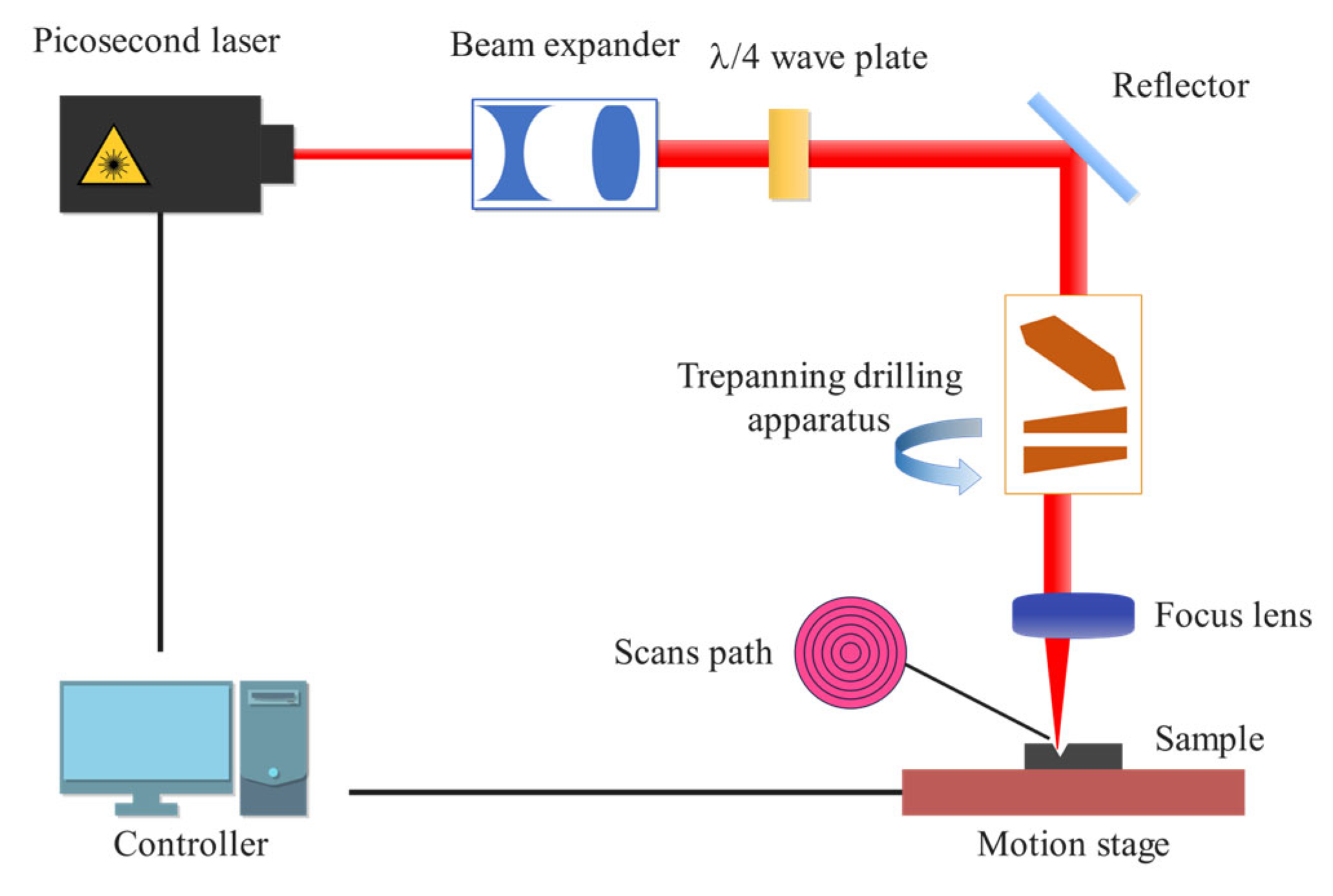
The experiments were conducted using a CNC precision picosecond laser machining center (Suzhou Delong Laser Co., Ltd., Suzhou, China), as depicted in Figure 1. The system is equipped with a picosecond laser source featuring a wavelength of 532 nm, a maximum power of 30 W (at a repetition rate of 1000 kHz), a tunable repetition rate ranging from 1 Hz to 2000 kHz, and a pulse width of less than 15 ps. In the optical path, the laser beam is directed through a beam expander, mirrors, and a scanning galvanometer before being focused onto the workpiece surface by an f-theta lens. This process induces a series of photo-thermal-mechanical effects, ultimately resulting in material removal.
Post-processing characterization was conducted using two instruments: a DSX100 ultra-depth-of-field 3D microscope (Olympus, Tokyo, Japan) and a QUANTA FEG 250 scanning electron microscope (SEM) (FEI Company, Hillsboro, OR, USA). The DSX100 microscope, featuring a 16× optical zoom and a ring LED (Olympus, Tokyo, Japan) illuminator, was employed to measure geometric parameters such as hole diameter, depth, and taper. The QUANTA FEG 250 SEM, owing to its superior resolution and magnification, was utilized to examine microstructural features, including hole wall details, the heat-affected zone (HAZ), and potential micro-cracks.

2.2. Experimental Design

Based on processing requirements and material characteristics, laser drilling can be categorized into three primary methods: single-pulse drilling, multi-pulse percussion drilling, and trepan drilling [23], as illustrated in Figure 2.
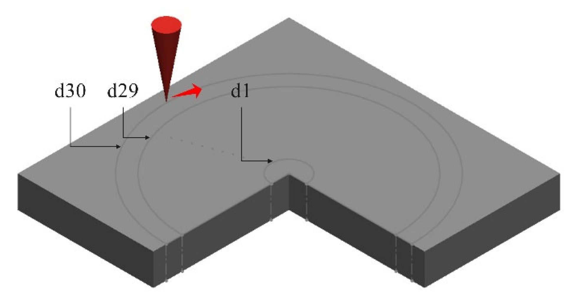
In this study, the trepanning technique was employed. This technique involves scanning the material surface multiple times, with each scan progressively deepening the hole until the desired diameter and depth are achieved. By carefully designing the scan path and number of iterations, this method allows for precise control over hole quality and dimensions, thereby ensuring high machining accuracy. Figure 3 illustrates the experimental scanning path, which consists of a series of concentric circles traced from the inside out. The path began with the innermost circle (d1) having a diameter of 0.01 mm. Each subsequent concentric circle’s diameter was increased by 0.01 mm, culminating in the outermost circle (d30) with a final diameter of 0.3 mm.

2.3. Assessment of Micro-Hole Quality

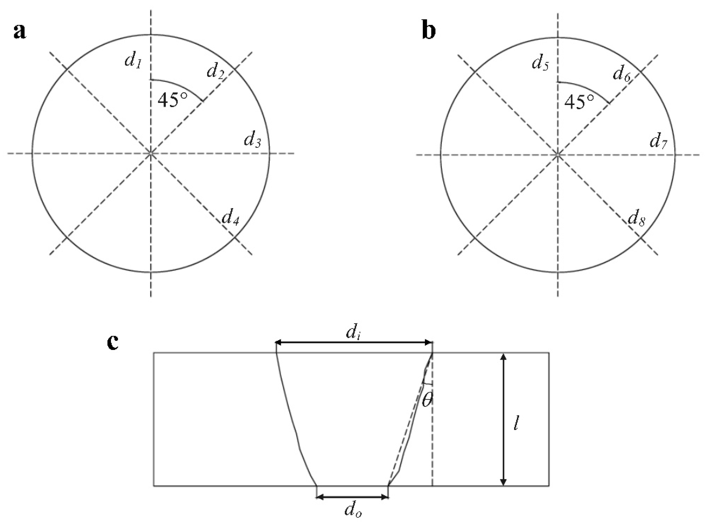
To minimize measurement errors, each hole was measured repeatedly from multiple orientations. As illustrated in Figure 4a,b, di and do represent the entrance and exit diameters, respectively. The diameters d1, d2, d3, and d4 were measured across four directions at the entrance, while d5, d6, d7, and d8 were measured at the exit. The angle between adjacent measurements was fixed at 45°. The final reported diameter is the arithmetic mean of these four measurements:
d i = d 1 + d 2 + d 3 + d 4 / 4
d o = d 5 + d 6 + d 7 + d 8 / 4
Taper (θ) quantifies the conical shape of the through-hole and is calculated based on the entrance diameter (di), exit diameter (do), and hole depth (l), as depicted in Figure 4c. The formula for taper is as follows:
θ = a r c t a n   d i d o 2 l   × 180 π
The roundness of the micro-hole was characterized by the standard deviation of the four diameter measurements. Here, σi and σo represent the roundness at the entrance and exit, respectively. The formulas are given by
σ i = ( d i d 1 ) 2 + ( d i d 2 ) 2 + ( d i d 3 ) 2 + ( d i d 4 ) 2 2
σ o = ( d i d 5 ) 2 + ( d i d 6 ) 2 + ( d i d 7 ) 2 + ( d i d 8 ) 2 2

3. Results

To systematically investigate the effect of laser processing parameters on the resulting micro-hole quality, a one-variable-at-a-time (OVAT) experimental methodology was adopted. This study focused on four key process parameters: laser power, number of scanning passes, scanning speed, and defocus distance. The quality of the fabricated micro-holes was evaluated based on both geometric accuracy (taper and roundness) and the extent of thermal damage. A critical aspect of this evaluation is the heat-affected zone. For the purposes of this study, a high-quality result with a “low HAZ” is defined by a combination of observable features: minimal dross and spatter on the component surface, a controlled and thin recast layer at the hole orifice, and the absence of micro-cracks [24,25].

3.1. Effect of Laser Power

Laser power, defined as the energy radiated by the laser per unit time, was controlled and reported as a percentage (%) of the equipment’s nominal maximum output power (Pmax = 30 W). To investigate the influence of this parameter on the quality of through-holes drilled in the GH4169 superalloy, the laser power was systematically varied while all other processing parameters were held constant. The specific experimental conditions are detailed in Table 2.
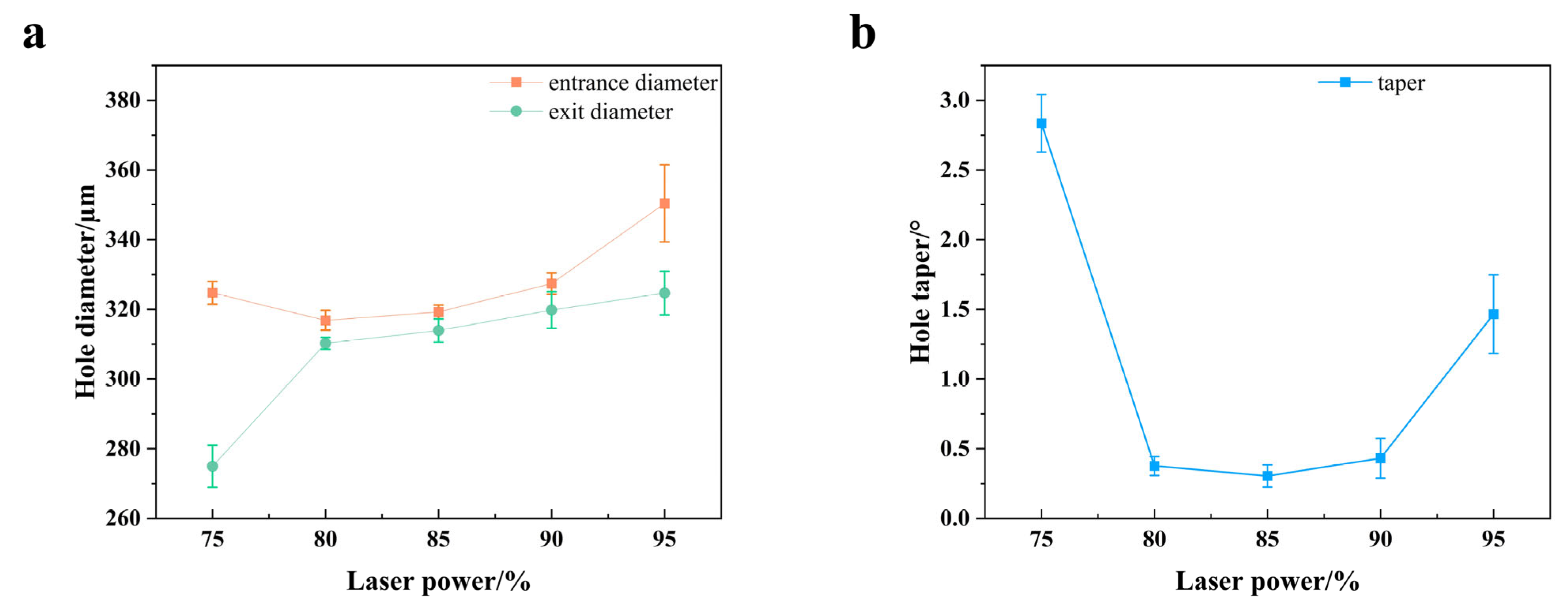
Figure 5 presents images of the micro-hole morphologies obtained from laser drilling experiments conducted at various laser power. Figure 6 illustrates the trends in entrance diameter, exit diameter, and hole taper as a function of varying laser power. As the laser power was increased, the entrance diameter exhibited a gradual upward trend. This is attributed to the fact that higher power levels deliver more incident energy per unit time, which broadens the melt and vaporization zone on the material surface. Given the Gaussian energy distribution of the laser beam, higher fluence in the center leads to strong ablation, while the energy in the periphery is still sufficient to cause melting, thus expanding the interaction area (Liu et al., 2016) [26]. Consequently, the laser interaction area expanded, leading to an enlarged entrance, as depicted in Figure 5a. Conversely, the exit diameter was markedly smaller at 75% power, indicating that the laser energy was insufficient for full penetration. This resulted in inadequate machining and minimal ablation at the hole bottom (Figure 5b). Beyond 80% power, the exit diameter increased rapidly. This sharp increase is due to the enhanced energy allowing the beam to penetrate deeper, thereby improving the melt-ejection efficiency for the material at the base of the hole. The hole taper initially decreased and then increased. At 75% power, the taper reached a high of 2.7°. It then dropped sharply to a minimum as power rose to the 80–90% range, before climbing again to approximately 1.6° at 95% power. This trend suggests that excessively low power leads to a pronounced taper, caused by insufficient melting at the hole exit combined with a larger entrance. Conversely, excessively high power may induce phenomena such as material remelting and spatter deposition, which also increases the taper.
Figure 7 depicts the trends in entrance and exit roundness as a function of laser power. As the power increased from 75% to 80%, the entrance roundness value slightly increased (indicating a slight degradation in quality). It then improved significantly, decreasing rapidly after 85% power and remaining at a consistently low level at 90% and 95%. This trend suggests that in the medium-to-high power range, a more sufficient energy input and enhanced beam stability contribute to the formation of a more uniform and well-defined entrance profile. In contrast, the exit roundness was low (indicating good circularity) at 75% and 80% power. However, as the power was increased to 85%, the roundness value abruptly surged to over 44 μm and remained at this elevated level for powers of 90% and 95%. This observation implies that under high-power conditions, while the laser possesses greater melting and penetration capabilities, the expanded heat-affected zone at the hole’s base makes phenomena such as material re-solidification and wall collapse more prone to occur, thereby degrading the roundness of the exit profile. This degradation is likely a result of increased heat accumulation, which promotes the formation of a larger molten pool and a thicker resolidified layer (Sun et al., 2019) [27].

3.2. Effect of Scanning Speed

Laser scanning speed is defined as the linear velocity of the laser beam as it moves across the workpiece surface. To investigate its influence on the fabrication of through-holes in the GH4169 superalloy, the scanning speed was systematically varied while all other laser parameters were held constant. The specific experimental conditions are detailed in Table 3.
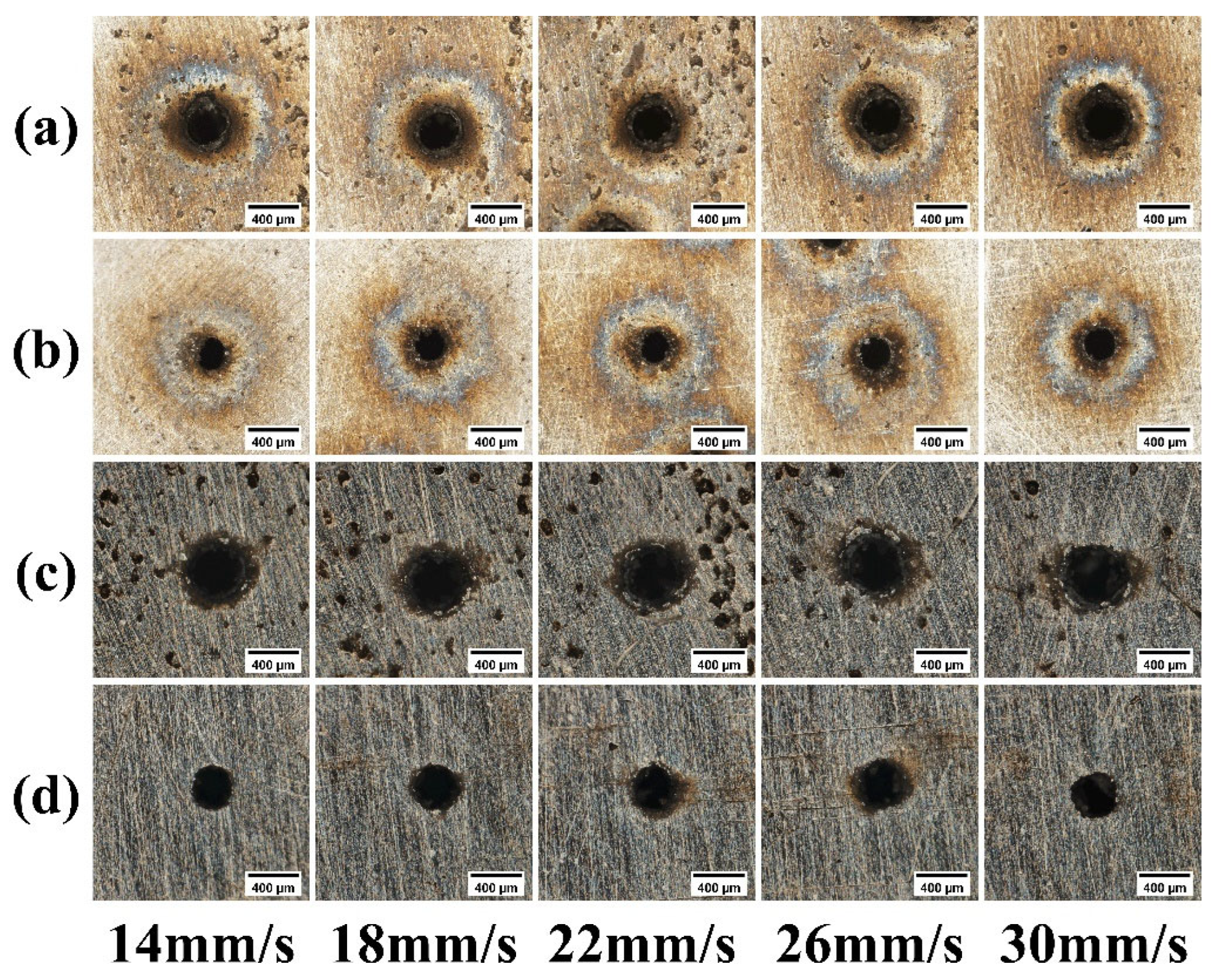
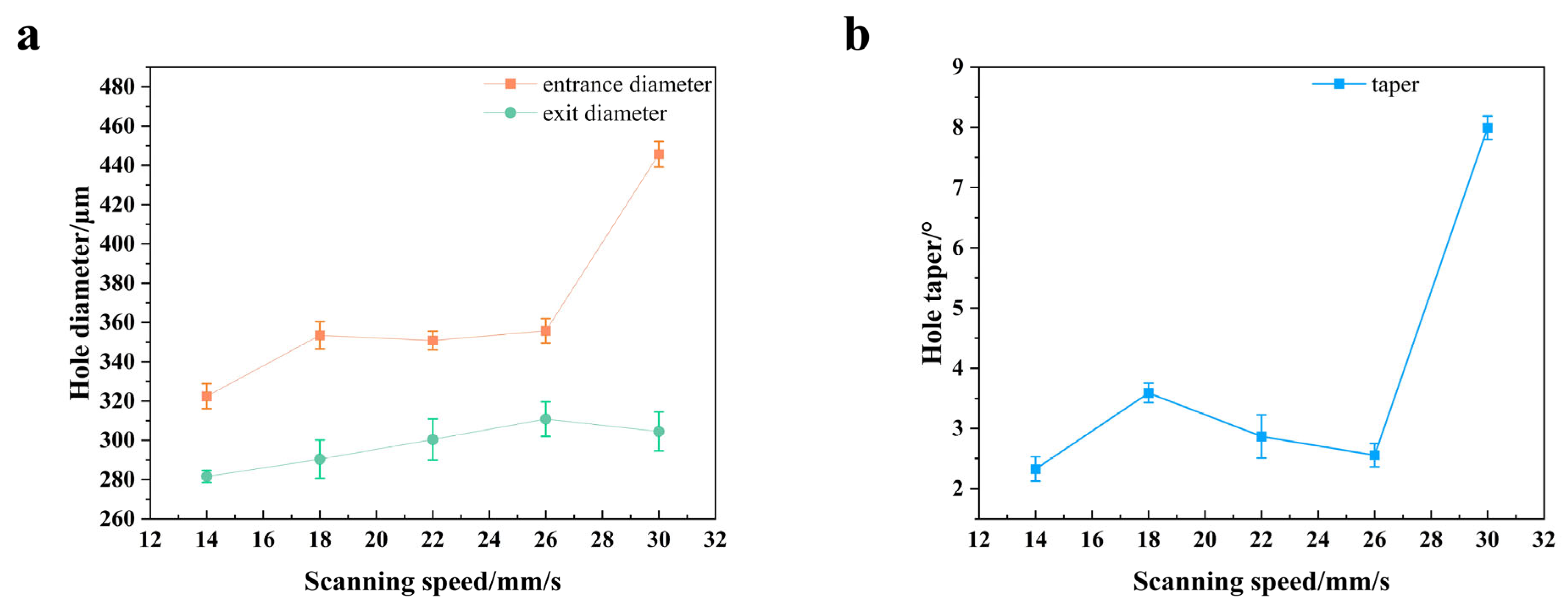
Figure 8 presents images of the micro-hole morphologies obtained from laser drilling experiments conducted at various scanning speed. As illustrated in Figure 9, an increase in scanning speed leads to a general upward trend in both the entrance diameter and the hole taper, whereas the exit diameter remains relatively constant. This phenomenon can be explained by the fact that at lower scanning speeds, the energy deposition per unit area is significantly higher. This allows the energy to effectively penetrate the entire material thickness and facilitates the efficient ejection of molten debris. Consequently, high-quality micro-holes with a small difference between entrance and exit diameters and a low taper are achieved. However, when the scanning speed becomes excessively high, the overlap rate of the laser pulses decreases, resulting in insufficient energy density being delivered to any single point on the material. The material at the upper section of the channel is over-melted due to heat accumulation and hindered molten material ejection, leading to a sharp increase in the entrance diameter. Simultaneously, the energy is severely attenuated as it propagates deeper into the hole, and by the time it reaches the bottom, it is insufficient for effective ablation. This causes the exit diameter to stagnate or even slightly decrease. Ultimately, the combination of the sharply enlarged entrance and the stagnant exit results in an increased hole taper.
Figure 10 illustrates the trends in entrance and exit roundness as a function of scanning speed. The roundness of both the entrance and exit initially deteriorates and then improves as the scanning speed increases, with the roundness error for both peaking at a speed of 22 mm/s. This phenomenon can be primarily attributed to the fact that at lower speeds, a high pulse overlap rate ensures stable energy input and uniform material removal, resulting in good roundness. As the speed increases into an intermediate range, the process enters an unstable regime. This instability is characteristic of processing with pulse durations near the material’s electron—phonon relaxation time, where the ablation mechanism can easily shift between vaporization-dominated and melt-dominated (Weck et al., 2008) [28]. In this state, the energy density is insufficient for pure vaporization-driven ablation but is high enough to generate a substantial volume of molten material. Concurrently, the faster scanning speed prevents the assist gas from ejecting this melt in a stable and uniform manner. This leads to the solidification of irregularly recast and spattered melt on the hole walls, which sharply degrades the roundness—an effect that is particularly pronounced at the exit, where debris ejection is more challenging. Conversely, as the speed is increased further, the energy input per unit area diminishes. Consequently, the volume of melt generated is reduced. The process thus transitions towards a “cold” ablation regime, which produces cleaner kerf edges (as seen in Figure 8d). As a result, the roundness paradoxically improves.

3.3. Effect of Defocus Amount

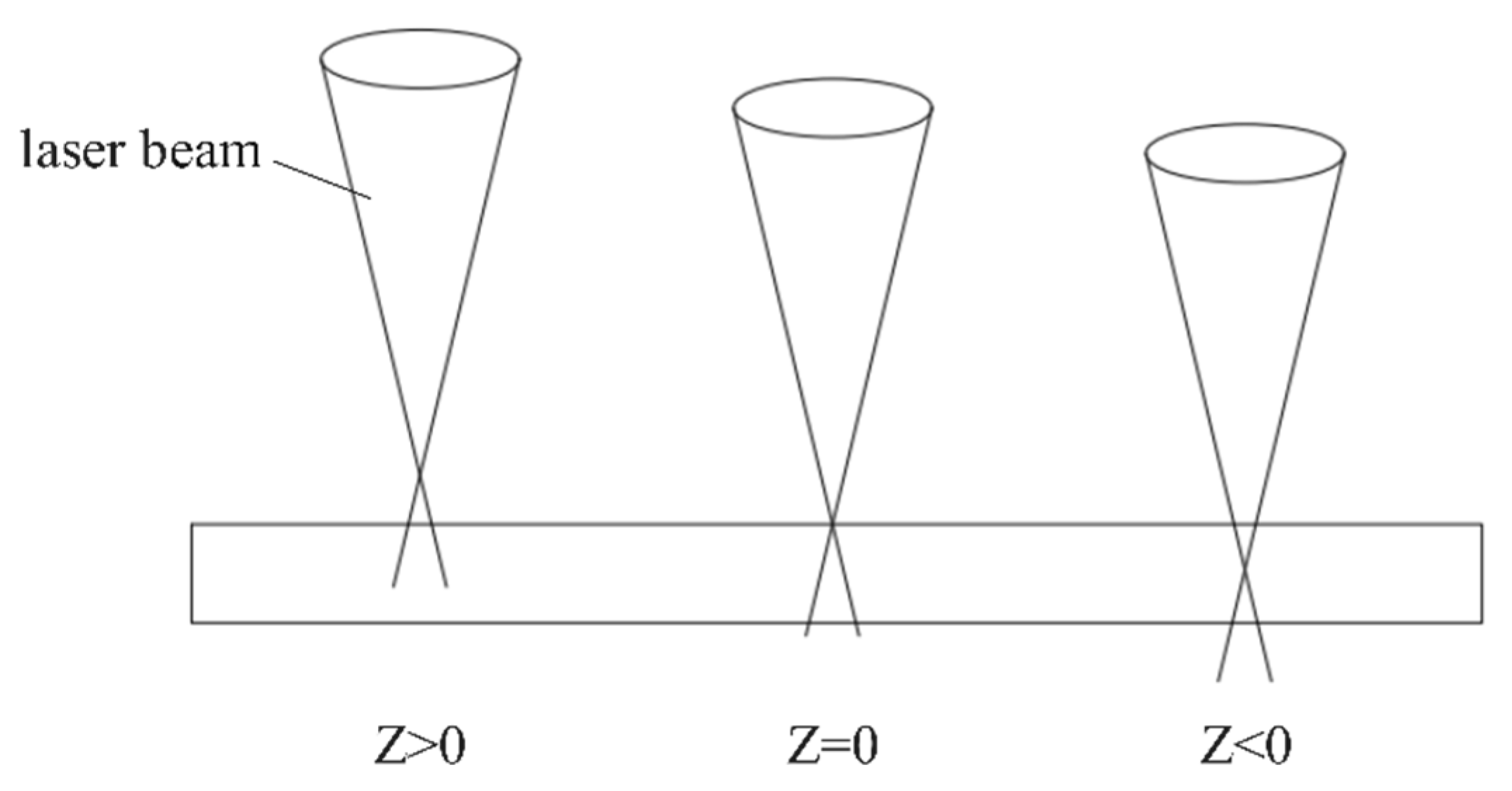
The defocus amount, commonly denoted by the symbol Z, is defined as the distance between the focal point of the laser beam and the surface of the workpiece during processing. As illustrated in Figure 11, this can be categorized into three types: positive defocus (when the focal point is above the surface), zero defocus (when the focal point is on the surface), and negative defocus (when the focal point is below the surface). To investigate the influence of this parameter, the defocus amount was varied from −0.2 mm to +0.2 mm while all other parameters were kept constant. The specific experimental conditions are presented in Table 4.
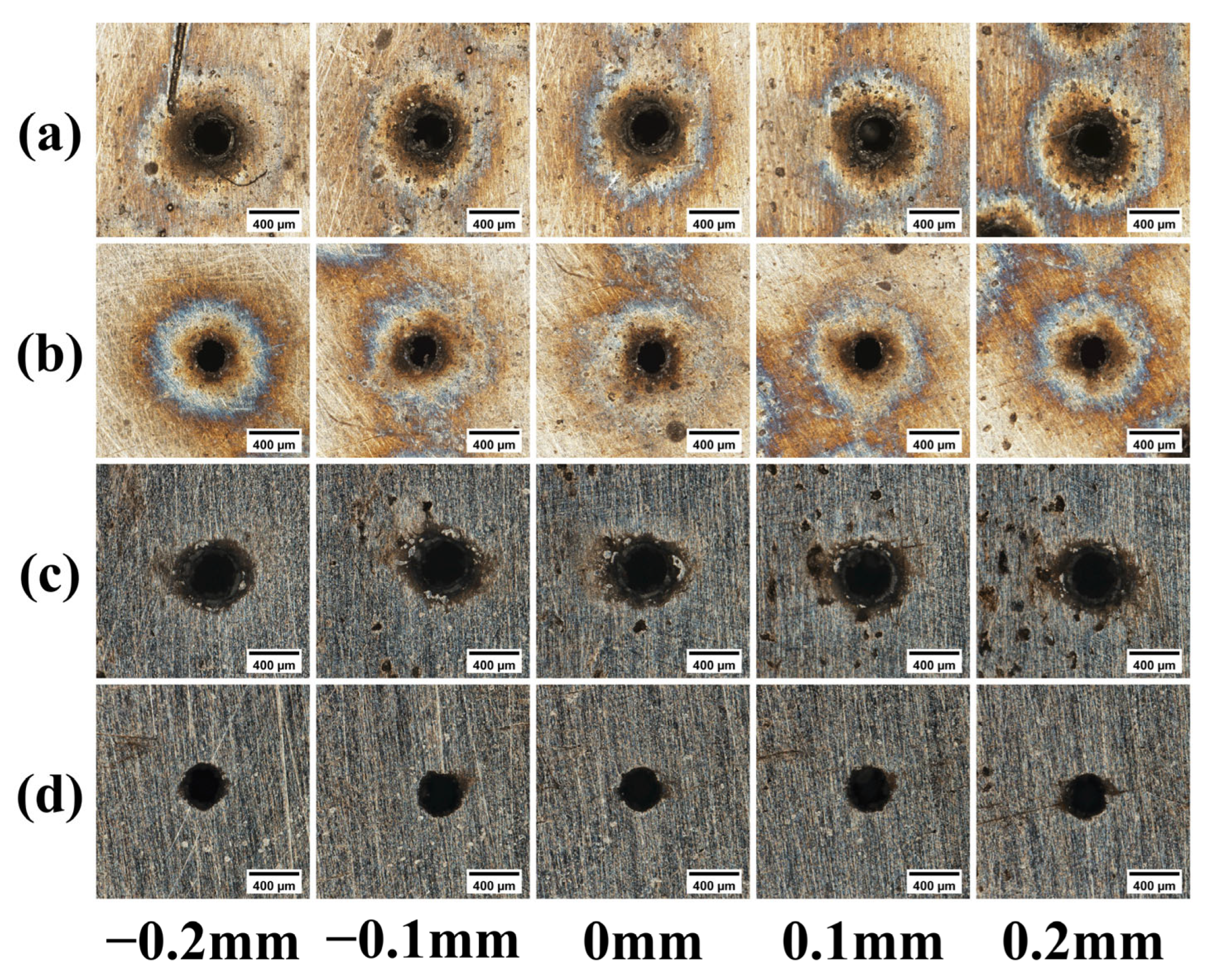
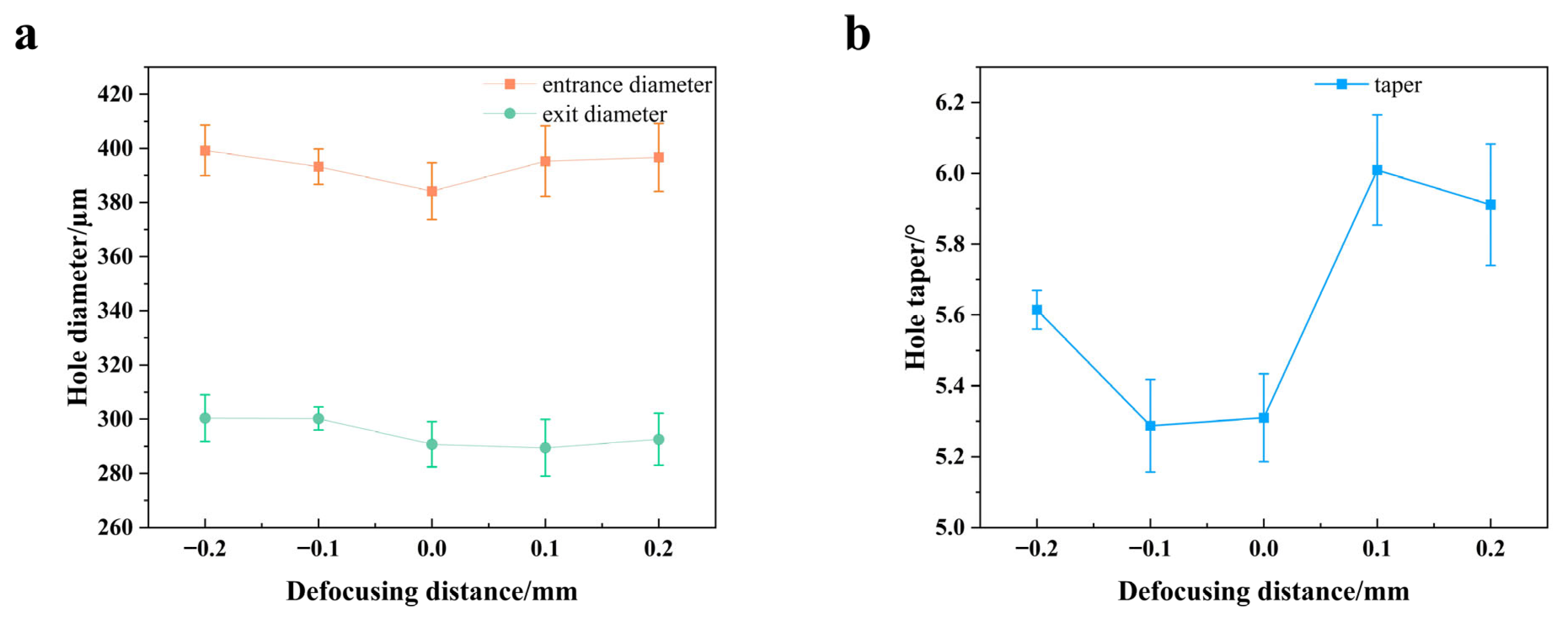
Figure 12 presents images of the micro-hole morphologies obtained from laser drilling experiments conducted at various defocusing distance. As depicted in Figure 13, the optimal processing results, characterized by the minimum taper, are achieved when the focal plane is positioned near the material surface. The rationale is that with zero or slightly negative defocus, the power density incident on the material surface is at its maximum, which facilitates highly efficient ablation. This high-intensity interaction minimizes thermal diffusion time, leading to direct material vaporization with minimal molten phase, which is the fundamental advantage of ultrashort pulse machining (Tünnermann et al., 2010) [29]. Simultaneously, as the beam propagates through the material, its energy remains sufficiently high over a considerable depth, thereby ensuring effective material removal at the exit. This ultimately yields a hole with a small difference between the entrance and exit diameters and, consequently, the lowest taper. Conversely, when a positive defocus is employed, the laser beam has already diverged by the time it reaches the material surface, resulting in a larger spot size and lower power density. This leads to an enlarged entrance diameter. As the beam penetrates deeper, it continues to diverge, causing a rapid attenuation of power density. This hinders material removal at the bottom, preventing the exit diameter from expanding effectively, which in turn leads to a sharp increase in taper. Similarly, when the negative defocus is excessive, although the focal point is located inside the material, the spot size on the surface is also enlarged. This reduces the initial ablation efficiency and is likewise detrimental to forming an ideal hole profile.
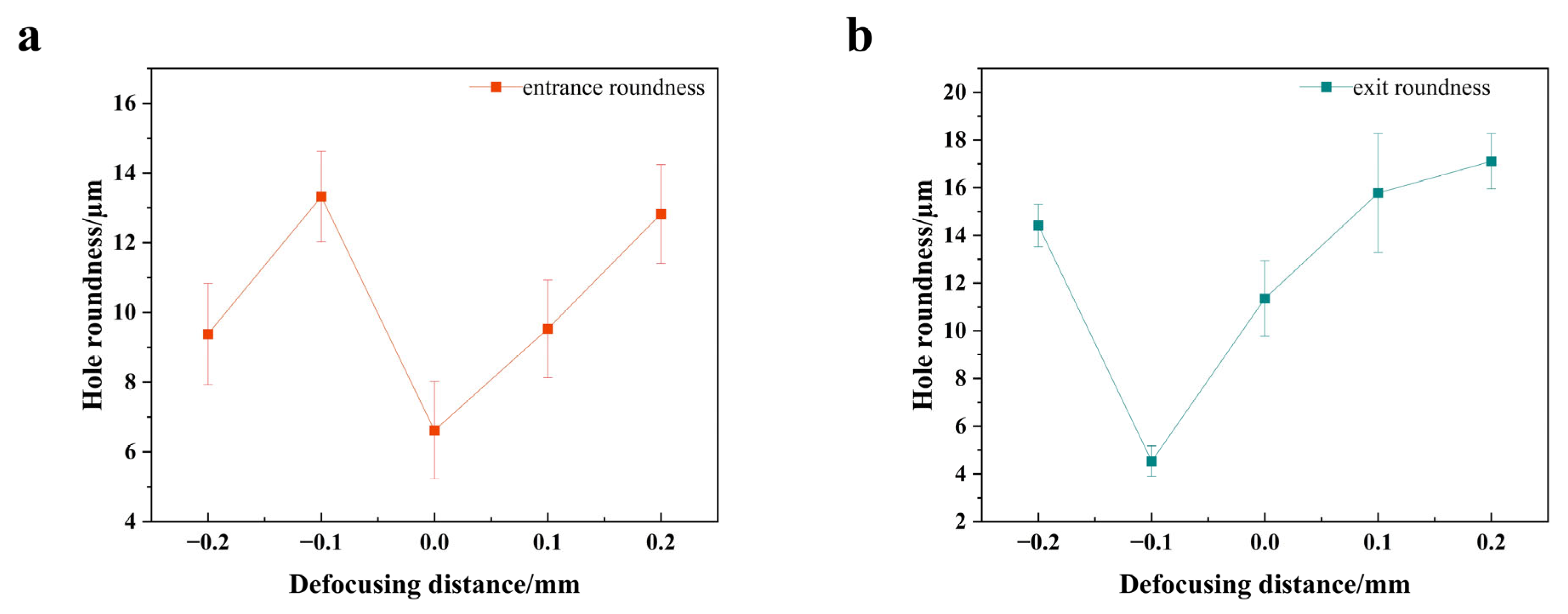
The variation of entrance and exit roundness as a function of the defocus amount is presented in Figure 14. The optimal exit roundness is observed at a defocus of −0.1 mm, whereas the best entrance roundness occurs at 0 mm. This phenomenon is fundamentally attributed to the way the defocus amount alters the distribution of laser energy along the material’s depth. At a defocus of −0.1 mm, the focal point is located beneath the material surface. This causes the laser beam to converge within the material and reach its peak energy density near the exit, which enables efficient and uniform penetration, resulting in excellent exit roundness. However, the corresponding energy density at the entrance is relatively low, which is prone to causing uneven melting and thus poor entrance roundness. At zero defocus (Z = 0), the energy density is maximized at the material surface, leading to optimal ablation (as shown in Figure 12a). Consequently, the best entrance roundness is achieved. However, the beam begins to diverge after passing through the focal point, leading to a reduced energy density by the time it reaches the exit. This results in insufficient and non-uniform melt ejection, which degrades the exit roundness. As the defocus amount increases further in either the positive or negative direction, the spot size on the material surface increases in both cases, reducing the energy density. This lower fluence pushes the process from being ablation-dominated to melting-dominated (Spiro et al., 2012) [30]. The process transitions from being ablation-dominated to melting-dominated. The resulting accumulation of molten material and irregular recast layers causes a significant deterioration in the roundness of both the entrance and exit.

3.4. Effect of the Number of Scans

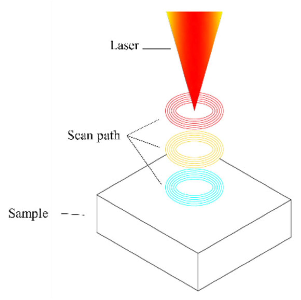
In this study, the number of scans is defined as the number of times the laser repeatedly processes a fixed trajectory. For picosecond laser drilling, a micro-hole is not formed by a single pulse but rather by a sequence of pulses with identical parameters. This multi-pulse process is illustrated in Figure 15. To isolate the effect of this variable, the number of scans was varied while all other process parameters were held constant. Specifically, the fixed parameters were a laser power of 80%, a defocus amount of 0 mm, and a scanning speed of 25 mm/s. The experimental design and the corresponding data are detailed in Table 5.
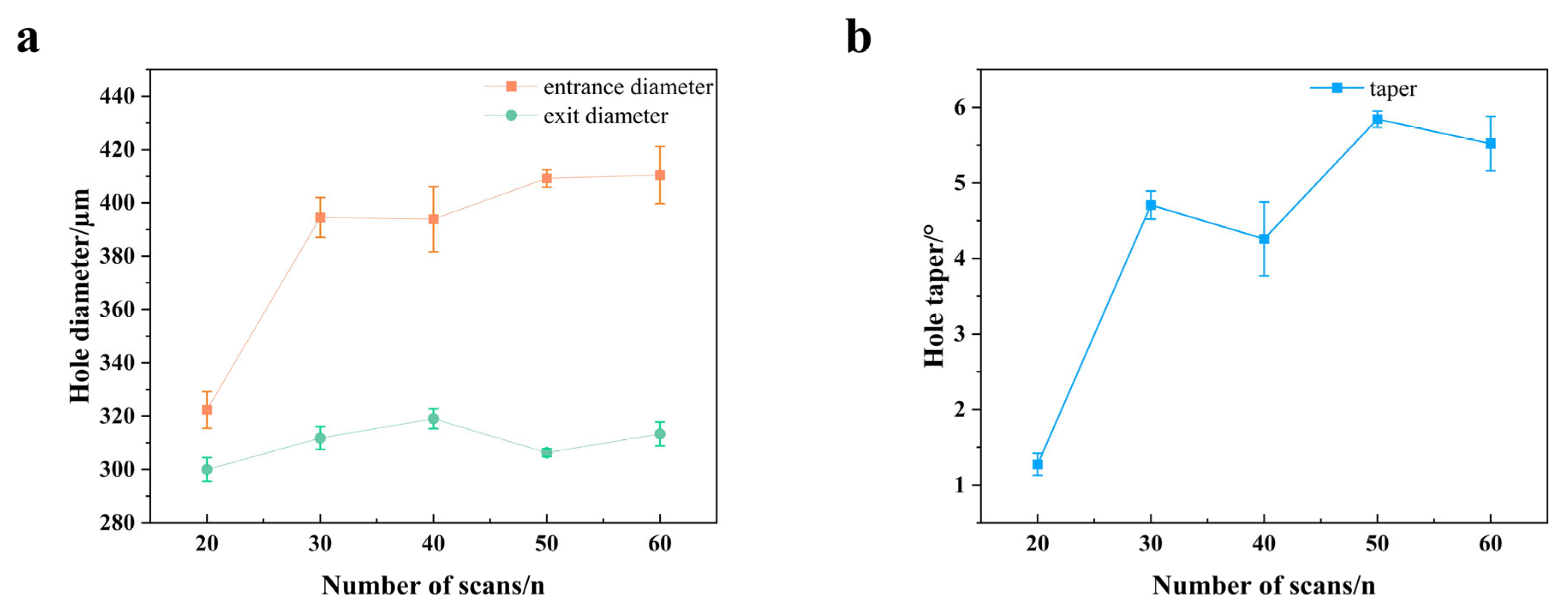
Figure 16 presents images of the micro-hole morphologies obtained from laser drilling experiments conducted at various number of scans. As depicted in Figure 17, with an increasing number of scans, both the entrance diameter and the taper exhibit a sharp upward trend, whereas the exit diameter changes more gradually. This is primarily because at a lower number of scans, the laser energy is predominantly utilized for effective ablation along the depth axis. The energy is just sufficient to penetrate the material, resulting in a small heat-affected zone and consequently a nearly vertical hole with minimal taper. However, as the number of scans increases significantly, the total injected laser energy rises proportionally. This leads to a substantial expansion of the ablated zone and causes the material removal mechanism to transition from pure vaporization to being dominated by melt ejection. Particularly at the hole entrance, the repeated heating of a large volume of molten material leads to a drastic expansion of the diameter. Meanwhile, with increasing hole depth, the plasma shielding effect becomes more pronounced, where the generated plasma plume can absorb and defocus the incident laser energy, partially attenuating the laser energy that reaches the bottom [19]. Simultaneously, the ejection of molten material becomes more difficult. This combination of factors restricts any further enlargement of the exit diameter.
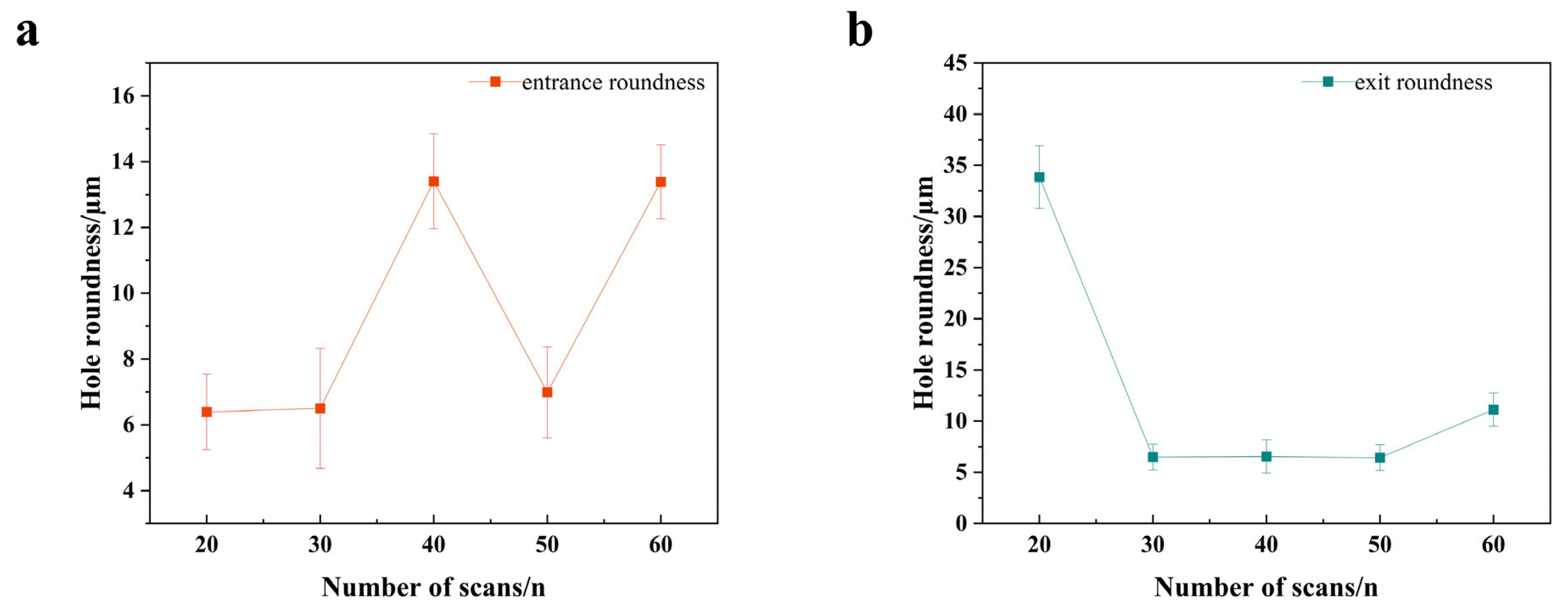
Figure 18 reveals a clear trend: at 20 scans, the entrance roundness is superior, while the exit roundness is extremely poor. As the scan count increases to 30, the exit roundness improves significantly and then stabilizes at a high level, whereas the entrance roundness begins to fluctuate and deteriorate. This phenomenon can be attributed to the following: at a low number of scans, the total energy is barely sufficient to penetrate the workpiece. The laser energy is severely attenuated by the time it reaches the exit, leading to incomplete and non-uniform material removal and thus extremely poor roundness. Conversely, the entrance benefits from low heat accumulation, resulting in a well-defined ablation profile and therefore excellent roundness (as depicted in Figure 16a,b). When the scan count is increased to 30, the cumulative energy becomes sufficient to achieve stable and uniform material removal at the exit, causing a dramatic improvement in its roundness. However, with further increases, the excessive energy accumulation begins to introduce adverse effects at the entrance, such as an enlarged heat-affected zone, irregular melt spatter, and recast material, which lead to the degradation of the entrance roundness. At an excessive number of scans, overwhelming thermal effects and plasma instability simultaneously impact both the entrance and exit, causing the roundness of both to deteriorate. Therefore, a range of 30–50 scans represents an optimal process window. This range ensures sufficient energy for complete penetration at the exit while avoiding the degradation of the entrance morphology caused by excessive energy accumulation.

3.5. Defect Control

Micro-hole defects have a severe adverse effect on the performance of superalloys. In terms of mechanical properties, the presence of micro-holes significantly degrades the material’s strength, ductility, and fatigue life. In the aerospace sector, the presence of such defects in metallic aircraft components can lead to premature crack initiation and eventual fracture, posing a severe threat to flight safety.
Based on the single-factor experiments, which revealed that a lower scan count is beneficial for reducing hole diameter and taper, the number of scans was further reduced. This process continued until the point of initial breakthrough, establishing a minimum required scan count of 9. The morphology of the resulting holes was then examined using a scanning electron microscope (SEM), as depicted in Figure 19.
Figure 19 displays the SEM micrographs of the hole entrances in a superalloy, processed with varying scan counts (N = 9, 20, 30, 40, 50, and 60) while other laser parameters were held constant. As the number of scans increases, the presence of dross and spatter around the hole orifice becomes increasingly pronounced. This aligns with observations in other materials, where an increase in total energy input, whether through higher power or more pulses, leads to a significant increase in the quantity of ejected debris and particles (Li et al., 2016) [31]. At a low scan count of N = 9, although an irregular, crown-like recast layer is present at the hole rim, the surrounding substrate surface remains relatively clean, with virtually no large, spherical spatter particles. As the scan count increases, a significant amount of dispersed, spherical dross and spatter particles begins to appear around the entrance, contaminating the component surface. This phenomenon is primarily attributed to the limited total energy input at low scan counts. This results in a smaller volume of molten material being generated. Concurrently, the plasma formed during the process is less intense, and its associated recoil pressure and shockwave are insufficient to eject molten droplets at high velocities over long distances.
The height of the recast material at the hole orifice was measured using a digital microscope (Olympus, Tokyo, Japan) (as shown in Figure 17), with the results presented in Table 6. The data indicate an upward trend in the recast material height with an increasing number of scans. This finding aligns with the preceding analysis, whereby intense thermal accumulation at high scan counts leads to the formation of a substantial volume of molten metal in the processing zone. This principle, where excessive scanning passes directly cause detrimental thermal accumulation, has been identified as a key factor in controlling processing quality in other advanced materials like CFRP (Zheng et al., 2024) [32]. The resolidification of this larger molten pool logically results in a thicker and more prominent recast layer, as depicted in Figure 20.
In conclusion, for applications involving turbine blades, a lower scan count is preferable as it corresponds to a minimal total heat input. A low scan count (N = 9, 20) fundamentally controls the total heat input, thereby preserving the original microstructure and properties of the superalloy substrate to the maximum extent possible. This significantly mitigates the risk of micro-crack initiation and ensures the fatigue life of the turbine blades under high thermal-cycling loads. This is a critical consideration, as studies on other brittle materials have shown that picosecond laser processing can still induce thermal stress-related defects like micro-cracks and edge fractures when processing parameters lead to high heat input (Zhu et al., 2018) [33]. Furthermore, under the N = 9 and N = 20 conditions, the amount of recast material on the hole surface is minimal. Conversely, at N ≥ 40, a substantial amount of recast material is present at the orifice, and the surrounding area is covered with extensive dross and spatter particles. These defects degrade the blade’s surface finish and, during engine operation, severely disrupt the boundary layer airflow. This leads to reduced cooling film effectiveness and increased aerodynamic losses.

4. Conclusions

This study systematically investigated the influence of key parameters—namely laser power, scanning speed, defocus, and scan count—on the geometrical quality of micro-holes trepanned in GH4169 superalloy using a picosecond laser. Based on the findings, an effective defect control strategy is proposed. The main conclusions are as follows:
1. The quality of laser-drilled holes is governed by a complex interplay of process parameters. Laser power and defocusing distance are the dominant factors for modulating hole taper; an optimal energy distribution, achieved within the 80–90% power range and at a defocusing distance of zero, is conducive to minimizing taper. However, a trade-off exists for roundness optimization: while a zero defocusing distance benefits the entrance, a slight negative defocusing distance is more effective for the exit. The influence of scanning speed is more intricate, as both excessively high and low speeds are detrimental to roundness, with the highest processing instability observed around 22 mm/s. Furthermore, the number of scans plays a pivotal role. Increasing the number of scans can rectify poor exit roundness caused by insufficient energy input, but an excessive number of scans leads to significant thermal accumulation. This in turn causes a sharp increase in the entrance diameter and taper, thereby degrading the entrance roundness.
2. A key finding of this study is that the optimal process parameters are highly dependent on the specific quality metric being prioritized, highlighting the critical trade-offs in the laser drilling process. For instance, to minimize hole taper, the ideal combination is an 85% laser power, a scanning speed of 26 mm/s, a defocusing distance of 0.0 mm, and a number of scans of 20. In contrast, achieving the minimum hole diameter requires a lower power (75%) and speed (14 mm/s) while keeping the same defocusing distance and number of scans. Furthermore, for applications demanding the highest exit roundness, the process must be tailored again, utilizing 80% power, a high speed of 30 mm/s, a negative defocusing distance of −0.1 mm, and a moderate number of scans (30–50).
3. A positive correlation was confirmed between the scan count and both the height of the recast layer and the extent of dross and spatter. High scan counts result in excessive recast material at the hole orifice. Accordingly, this study proposes a defect control strategy: utilizing the minimum scan count necessary to achieve workpiece breakthrough. This approach prioritizes the integrity of the substrate material by fundamentally reducing the total heat input, thus minimizing recast layer and spatter defects to the lowest possible level.
From an industrial perspective, these findings directly address the limitations of conventional machining, namely tool wear and thermal damage. Although the initial capital cost of picosecond laser systems is significant, their value proposition in manufacturing critical components like turbine blade cooling holes is undeniable. The proposed defect control strategy (using a minimal scan count) enhances both processing quality and efficiency, leading to tangible economic benefits through reduced scrap rates and the elimination of tool-related costs. Ultimately, this work establishes a practical manufacturing framework that effectively bridges the gap between advanced laser technology and its high-quality industrial application.

Author Contributions

Conceptualization, L.W. and K.X.; Methodology, Y.R.; Software, C.W.; Validation, L.X. and C.W.; Formal Analysis, L.X.; Writing—original draft, Y.R.; Writing—review and editing, L.W., K.X., L.X. and C.W.; Supervision, L.W.; Project administration, L.W.; Funding acquisition, L.W. and K.X. All authors have read and agreed to the published version of the manuscript.

Funding

This research was supported by the National Natural Science Foundation of China (grant numbers 52375434 and 52205469), and Major Research Projects of the Natural Science Research Foundation of Jiangsu Higher Education Institutions (grant number 23KJA460003), and the Postgraduate Research and Practice Innovation Program of Huaiyin Institute of Technology (grant number HGYK202508).

Data Availability Statement

The original contributions presented in this study are included in the article. Further inquiries can be directed to the corresponding author.

Conflicts of Interest

The authors declare no conflicts of interest.

References

  1. Wang, C.; Wang, Q.; Qian, Q.; Di, B. The development of laser drilling: A review. In Proceedings of the IOP Conference Series: Materials Science and Engineering, Qingdao, China, 28–29 December 2020; p. 022067. [Google Scholar]
  2. Wang, S.; Xie, W.; Ding, Y.; Liu, H.; Zhang, X.; Yang, L.; Chen, X.; Chen, M.; Zhang, W.; Lu, Y. Investigations on the Water-Jet Guided Laser drilling film cooling holes on the 8.5 mm-thick TBC superalloy. J. Manuf. Process. 2024, 125, 374–388. [Google Scholar] [CrossRef]
  3. Xia, K.; Ren, N.; Lin, Q.; Yang, H. Femtosecond laser drilling in superalloy with water-based magnetic assistance. Opt. Commun. 2023, 527, 128902. [Google Scholar] [CrossRef]
  4. Li, Z.; Wang, C.; Wen, Z.; Yue, Z. Surface integrity and low cycle fatigue behavior of Ni-based single-crystal film with cooling holes processed by ECM, EDM and PLM. Eng. Fract. Mech. 2025, 326, 111378. [Google Scholar] [CrossRef]
  5. Liu, G.; Li, Y.; Kong, Q.; Tong, H. Research on ECM process of micro holes with internal features. Precis. Eng. 2017, 47, 508–515. [Google Scholar] [CrossRef]
  6. Tamang, S.; Natarajan, N.; Chandrasekaran, M. Optimization of EDM process in machining micro holes for improvement of hole quality. J. Braz. Soc. Mech. Sci. Eng. 2017, 39, 1277–1287. [Google Scholar] [CrossRef]
  7. Sarfraz, S.; Shehab, E.; Salonitis, K. A review of technical challenges of laser drilling manufacturing process. In Advances in Manufacturing Technology XXXI, Proceedings of the 15th International Conference on Manufacturing Research, London, UK, 5–7 September 2017; Sage: Thousand Oaks, CA, USA; pp. 51–56.
  8. Antar, M.; Chantzis, D.; Marimuthu, S.; Hayward, P. High speed EDM and laser drilling of aerospace alloys. Procedia Cirp 2016, 42, 526–531. [Google Scholar] [CrossRef]
  9. Karim, M.A.; Jahan, M.P. Effectiveness of Electrode Design Methodologies for Fast EDM Slotting of Thick Silicon Wafers. Appl. Sci. 2025, 15, 6374. [Google Scholar] [CrossRef]
  10. Fan, R.; Mei, X.; Cui, J. Process in laser drilling of deep microholes without taper on metal materials. Sci. China Technol. Sci. 2024, 67, 37–59. [Google Scholar] [CrossRef]
  11. Jia, X.; Chen, Y.; Liu, L.; Wang, C.; Duan, J.a. Advances in laser drilling of structural ceramics. Nanomaterials 2022, 12, 230. [Google Scholar] [CrossRef]
  12. Tang, Z.-Q.; Li, Y.-F.; Wang, G.; Yu, Y.; Cao, H.; Li, L.-F.; Jin, Z.-S.; Wang, Y.-L.; Lu, Z. Research advances of femtosecond laser drilling microholes in hard and brittle materials. Opt. Laser Technol. 2025, 185, 112572. [Google Scholar] [CrossRef]
  13. Sahoo, N.; Carvalho, O.; Özcan, M.; Silva, F.; Souza, J.C.; Lasagni, A.-F.; Henriques, B. Ultrashort pulse laser patterning of zirconia (3Y-TZP) for enhanced adhesion to resin-matrix cements used in dentistry: An integrative review. J. Mech. Behav. Biomed. Mater. 2023, 143, 105943. [Google Scholar] [CrossRef] [PubMed]
  14. Ebenezer, G.; Adam Khan, M.; Winowlin Jappes, J. Influence of short-pulsed laser and its thermal effect on micromachining of NiTi alloy. Sādhanā 2022, 47, 201. [Google Scholar] [CrossRef]
  15. Wang, X.; Huang, Y.; Li, C.; Xu, B. Numerical simulation and experimental study on picosecond laser ablation of stainless steel. Opt. Laser Technol. 2020, 127, 106150. [Google Scholar] [CrossRef]
  16. Deepu, P.; Jagadesh, T. A review on short and ultrashort pulsed laser microdrilling: Materials, mechanism, methods, and applications. J. Braz. Soc. Mech. Sci. Eng. 2024, 46, 408. [Google Scholar] [CrossRef]
  17. Račiukaitis, G. Ultra-short pulse lasers for microfabrication: A review. IEEE J. Sel. Top. Quantum Electron. 2021, 27, 1–12. [Google Scholar] [CrossRef]
  18. Zhu, H.; Xie, W.; Du, W.; Zhang, Q.; Yuan, H.; Xu, K.; Liu, Y.; Wang, J.; Saetang, V.; Zhang, Z. Fabrication and quality improvement of film cooling holes via picosecond laser drilling assisted by waterjet and post-electrochemical machining. Opt. Laser Technol. 2025, 182, 112162. [Google Scholar] [CrossRef]
  19. Tang, Q.; Wu, C.; Wu, T. Defocusing effect and energy absorption of plasma in picosecond laser drilling. Opt. Commun. 2021, 478, 126410. [Google Scholar] [CrossRef]
  20. Wang, H.; Yu, G.; Xin, W.; Wang, Y.; Kong, X. New solution for machining deep high-aspect-ratio micro holes based upon picosecond laser layered trepanning. Opt. Laser Technol. 2025, 189, 113107. [Google Scholar] [CrossRef]
  21. Liu, C.; Li, C.; Gao, L.; Shen, R. Micro-hole drilling of 2.5 DC/SiC composite with picosecond laser: Numerical modeling and experimental validation on hole shape evolution. J. Manuf. Process. 2022, 81, 852–864. [Google Scholar] [CrossRef]
  22. Zhang, X.; Zhang, Z.; Zhu, H.; Li, S.; Wang, Y.; Xu, K.; Chu, S.; Huang, J. Mass Fabrication of Microholes in Aviation Kerosene Filters Using the Back-water-assisted Picosecond Laser Drilling Technique. Lasers Eng. 2022, 52, 37. [Google Scholar]
  23. Kannatey-Asibu, E. Laser Cutting and Drilling. In Principles of Laser Materials Processing: Developments and Applications; Wiley: Hoboken, NJ, USA, 2023; pp. 279–334. [Google Scholar]
  24. Zhang, H.; Di, J.; Zhou, M.; Yan, Y.; Wang, R. An investigation on the hole quality during picosecond laser helical drilling of stainless steel 304. Appl. Phys. A 2015, 119, 745–752. [Google Scholar] [CrossRef]
  25. Zhang, H.; Di, J.; Zhou, M.; Yan, Y. A comparison in laser precision drilling of stainless steel 304 with nanosecond and picosecond laser pulses. Chin. J. Mech. Eng. 2014, 27, 972–977. [Google Scholar] [CrossRef]
  26. Yu, Z.; Hu, J.; Li, K. Investigating the multiple-pulse drilling on titanium alloy in picosecond laser. J. Mater. Process. Technol. 2019, 268, 10–17. [Google Scholar] [CrossRef]
  27. Sun, X.; Dong, X.; Wang, K.; Wang, R.; Fan, Z.; Duan, W. Experimental investigation on thermal effects in picosecond laser drilling of thermal barrier coated In718. Opt. Laser Technol. 2019, 113, 150–158. [Google Scholar] [CrossRef]
  28. Weck, A.; Crawford, T.; Wilkinson, D.; Haugen, H.; Preston, J. Laser drilling of high aspect ratio holes in copper with femtosecond, picosecond and nanosecond pulses. Appl. Phys. A 2008, 90, 537–543. [Google Scholar] [CrossRef]
  29. Tuennermann, A.; Nolte, S.; Limpert, J. Femtosecond vs. picosecond laser material processing: Challenges in ultrafast precision laser micromachining of metals at high repetition rates. Laser Tech. J. 2010, 7, 34–38. [Google Scholar] [CrossRef]
  30. Spiro, A.; Lowe, M.; Pasmanik, G. Drilling rate of five metals with picosecond laser pulses at 355, 532, and 1064 nm. Appl. Phys. A 2012, 107, 801–808. [Google Scholar] [CrossRef]
  31. Li, W.; Zhang, R.; Liu, Y.; Wang, C.; Wang, J.; Yang, X.; Cheng, L. Effect of different parameters on machining of SiC/SiC composites via pico-second laser. Appl. Surf. Sci. 2016, 364, 378–387. [Google Scholar] [CrossRef]
  32. Zheng, Z.; Ma, Y.; Wang, Z.; Liu, S.; Wu, C. Dual-method characterization and optimization of drilling parameters for picosecond laser drilling quality in CFRP. Polymers 2024, 16, 2603. [Google Scholar] [CrossRef]
  33. Zhu, H.; Zhang, Z.; Xu, J.; Xu, K.; Ren, Y. An experimental study of micro-machining of hydroxyapatite using an ultrashort picosecond laser. Precis. Eng. 2018, 54, 154–162. [Google Scholar] [CrossRef]
Figure 1. Laser drilling device.
Metals 15 00893 g001
Figure 2. Schematic diagram of laser drilling hole. (a) Single-pulse drilling. (b) Multi-pulse percussion drilling. (c) Trepan drilling.
Metals 15 00893 g002
Figure 3. Scanning path diagram.
Metals 15 00893 g003
Figure 4. Micro-hole feature characterization: (a) Entrance diameter, (b) Exit diameter; (c) Taper.
Metals 15 00893 g004
Figure 5. Effect of laser power on micro-hole morphology. (a) Micro-hole entrance before polishing. (b) Micro-hole exit before polishing. (c) Micro-hole entrance after polishing. (d) Micro-hole exit after polishing.
Metals 15 00893 g005
Figure 6. Effect of laser power on hole diameter and taper. (a) Hole diameter. (b) Hole taper.
Metals 15 00893 g006
Figure 7. Effect of laser power on hole roundness: (a) entrance; (b) exit.
Metals 15 00893 g007
Figure 8. Effect of scanning speed on hole morphology (a) Hole entrance before polishing. (b) Hole exit before polishing. (c) Hole entrance after polishing. (d) Hole exit after polishing.
Metals 15 00893 g008
Figure 9. Effect of scanning speed on hole diameter and taper (a) Hole diameter. (b) Hole taper.
Metals 15 00893 g009
Figure 10. Effect of scanning speed on hole roundness: (a) entrance; (b) exit.
Metals 15 00893 g010
Figure 11. Schematic diagram of defocusing distance.
Metals 15 00893 g011
Figure 12. Effect of defocusing distance on hole morphology (a) Hole entrance before polishing. (b) Hole exit before polishing. (c) Hole entrance after polishing. (d) Hole exit after polishing.
Metals 15 00893 g012
Figure 13. Effect of defocusing distance on hole diameter and taper (a) Hole diameter. (b) Hole taper.
Metals 15 00893 g013
Figure 14. Effect of defocusing distance on hole roundness: (a) entrance; (b) exit.
Metals 15 00893 g014
Figure 15. Schematic diagram of number of scans.
Metals 15 00893 g015
Figure 16. Effect of number of scans on hole morphology (a) Hole entrance before polishing. (b) Hole exit before polishing. (c) Hole entrance after polishing. (d) Hole exit after polishing.
Metals 15 00893 g016
Figure 17. Effect of number of scans on hole diameter and taper: (a) Hole diameter; (b) Hole taper.
Metals 15 00893 g017
Figure 18. Effect of number of scans on hole roundness (a) entrance. (b) exit.
Metals 15 00893 g018
Figure 19. SEM micrographs of hole entrance morphology under different numbers of scans.
Metals 15 00893 g019
Figure 20. Resolidification height at hole entrance under different numbers of scans.
Metals 15 00893 g020
Table 1. Chemical composition of superalloy GH4169.
CompositionNiCrSiMnCMoSPFeAlTiNbCoCu
Mass Fraction/%51.818.30.330.140.0462.970.0020.009Allowance0.580.955.150.340.07
Table 2. Laser power parameters.
Laser Power/(%)Number of Scans/(n)Scanning Speed/(mm/s)Defocusing Distance/(mm)
75/80/85/90/9525250
Table 3. Scanning speed parameters.
Laser Power/(%)Number of Scans/(n)Scanning Speed/(mm/s)Defocusing Distance/(mm)
802514/18/22/26/300
Table 4. Defocusing distance parameters.
Laser Power/(%)Number of Scans/(n)Scanning Speed/(mm/s)Defocusing Distance/(mm)
802525−0.2/−0.1/0/0.1/0.2
Table 5. Number of scans parameters.
Laser Power/(%)Number of Scans/(n)Scanning Speed/(mm/s)Defocusing Distance/(mm)
8020/30/40/50/60250
Table 6. Resolidification height data.
Number of Scans/(n).Recast Layer Height/(μm) *
990.1
20131.6
30181.2
40143.5
50152.2
*—Values represent the approximate maximum height of the irregular recast layer and are intended to show a trend.
Disclaimer/Publisher’s Note: The statements, opinions and data contained in all publications are solely those of the individual author(s) and contributor(s) and not of MDPI and/or the editor(s). MDPI and/or the editor(s) disclaim responsibility for any injury to people or property resulting from any ideas, methods, instructions or products referred to in the content.