Abstract
With the rapid advancement of new energy electric vehicles, high-capacity nickel-rich layered oxides have emerged as predominant cathode materials in lithium-ion battery systems. However, their widespread implementation necessitates rigorous investigation into cycling stability. We synthesized nickel-manganese-aluminum hydroxide precursors as raw materials by co-precipitation method, and synthesized ultrathin Al2O3-coated LiNi0.9Mn0.05Al0.05O2 cathode materials by hydrolysis reaction. The cathode material was uniformly covered by an Al2O3 layer with an average thickness of 5–10 nm by high resolution transmission electron microscopy (HRTEM). Electrochemical performance tests showed that the modified cathode material exhibited significantly enhanced reversible capacity, cycling stability, and rate performance, and a more favorable differential capacity curve. In particular, the LNMA-2 samples were able to maintain 90.6% and 88.3% of their initial capacity after 100 cycle tests (with cutoff voltages of 4.3 and 4.5 V, respectively) at 0.5 C charge/discharge rate. These improved electrochemical properties are mainly attributed to the advantages offered by the unique Al2O3 coating structure. This study provides significant theoretical value for designing and optimizing the production of high-nickel cobalt-free cathode materials with high cycling performance.
1. Introduction
Driven by exponential growth in portable electronics and electrified transportation sectors, lithium-ion batteries (LIBs) have solidified their position as the primary energy storage solution, with global demand exhibiting sustained upward trajectories [1,2]. In the pursuit of high-performance lithium-ion batteries, cathode materials play an indispensable role [3,4,5]. Recent research frontiers have consequently focused on the strategic development of cobalt-free architectures, particularly nickel-manganese-aluminum (Ni-Mn-Al) oxide systems demonstrating exceptional specific capacities coupled with intrinsic thermal stability—a critical advancement addressing the structural-electrochemical stability nexus in high-energy cathode design [6,7,8].
Despite the accelerated development of layered oxide cathode materials containing high nickel (Ni > 70%) in high-energy density lithium-ion batteries, they still face several unresolved key instability challenges [9]. These challenges predominantly manifest as structural instabilities including lattice/surface degradation, aggravated Li+/Ni2+ cation disordering, and accelerated interfacial electrolyte decomposition, coupled with potential oxygen evolution, surface phase reconstruction, and multiphase transition-induced lattice distortions. Under high-voltage operation (> 4.3 V), electrolyte decomposition initiates detrimental side reactions at the cathode–electrolyte interface, accelerating transition metal dissolution. These decomposition byproducts subsequently migrate to the cathode surface, triggering continuous remodeling of the cathode–electrolyte interface (CEI), inducing structural heterogeneity and impedance buildup, ultimately resulting in rapid capacity fading during prolonged cycling. These factors lead to the rapid capacity decay of the material during long-term charging and discharging [10,11,12]. To address the inherent instability of high-nickel cathodes and enhance their cycling durability, a holistic optimization framework encompassing compositional engineering, interfacial stabilization, and electrolyte formulation innovations has emerged as an effective strategy, synergistically addressing bulk structural degradation, interface side reactions, and electrolyte compatibility issues to prolong cycle life [13,14].
In order to enhance the structural stability and electrochemical performance of high-Ni cathode materials, researchers have conducted extensive studies. Typically, the use of elemental doping has proved to be particularly effective, not only in suppressing the occurrence of Li/Ni antisite defects, but also in modulating the lattice structure of the base-rich lithium cathode materials and thus optimizing the electrochemical performance [15]. Zhou et al. [16] doped nickel-manganese-aluminum (Ni-Mn-Al) cathode materials with low-valent Ca2+ ions, which are easier to occupy the nickel-manganese-aluminum (Ni-Mn-Al) cathode materials due to their relatively low electronegativity and large ionic radius (1.00 Å), and Ca2+ ions are more likely to occupy the TM layer sites in the cathode material compared to transition metal (TM) ions and can cause the expansion of the lattice parameter, thus providing fast Li migration channels and an ordered layer structure. The results show that the Ca2+-doped cathode material demonstrates a superior cycling stability compared to the nickel-manganese-aluminum cathode. The capacity retention rate is as high as 94.9% at a charge/discharge multiplication rate of 1 C, and at a high rate performance of 10 C, the capacity retention still reaches 73.4%. Yanet al. [17] demonstrated that Mg-Nb-Zr tri-element co-doping in Ni-Mn-Al cathodes effectively refines grain size, suppresses Li+/Ni2⁺ cation mixing, expands interlayer spacing, stabilizes crystallographic configuration, inhibits microcrack nucleation/propagation, and reduces interfacial side reactions, thereby significantly enhancing cycling stability under high-voltage operation. Nevertheless, dopant incorporation with significant ionic radius mismatch or crystallographic incompatibility introduces localized lattice strain fields, propagating anisotropic stress accumulation that compromises structural integrity through dislocation pile-ups and grain boundary embrittlement, ultimately degrading electrochemical performance in layered oxide cathodes [18,19].
In addition to elemental doping, surface engineering has become another important way to improve structural stability [20,21]. Various types of cathode surface coatings have been reported, covering from metal-based materials such as metal oxides and metal phosphates [22,23,24]. In addition, different coating processes affect the thickness, morphology of the coating, and its final performance [25,26]. Manthiram et al. [27] used phosphate coating to form a protective film on the surface of nickel-manganese-aluminum cathode material, and the battery had higher capacity retention and less voltage degradation. Due to the low cost of Al2O3 layer, it has good Li ion conductivity [28,29,30,31]. Zhang et al. [32] used aluminum isopropoxide to parcel the cathode material LiNi0.5Co0.2Mn0.3O2, and used the Li residual on the surface of the cathode material at high temperature to react with aluminum isopropoxide to generate the LiAlO2-coating layer with fast migration, and found that the introduction of different thicknesses of the parcel layer could improve the capacity retention rate of the battery. However, the above encapsulation method requires twice calcination of the cathode materials, which increases the cost of preparing cathode materials. Kim et al. [31] used aluminum isopropoxide dissolved in anhydrous ethanol and nickel-cobalt-manganese precursor reaction to prepare Al2O3-encapsulated materials, which improves the rate performance and cycling stability of cathode materials, but neglects the problem of homogeneous precipitation of encapsulated materials. Therefore, the need for precursor parcels to develop synthesis with uniform coating thickness and improve the cycling stability of high nickel-manganese-aluminum cathode materials is crucial.
Therefore, in this work, we report hydrolysis-high-temperature treatment method to successfully prepare a complete ultrathin Al2O3-coating Li1.05Ni0.9Mn0.05Al0.05O2 cathode material. During the hydrolysis process, the precursor nickel-manganese-aluminum hydroxide was used as the raw material to synthesize the Al(OH)3 precursor wrapped layer in situ. During the calcination process, the surface Al(OH)3 was dehydrated to produce Al2O3 [33]. In addition, the Al2O3-layered structure facilitates the diffusion of Al3+ ions into the cathode material during calcination. Compared with the conventional structure, the main function of this unique inlay structure is to act as a protective passivation film to prevent the cathode material from coming into direct contact with the electrolyte, thus slowing down the harmful side reactions that may degrade the performance of the battery, and it also buffers the volume change of the core and shell layers during the cycling process. The cathode material, after coating, was able to maintain 90.6% and 88.3% of its initial capacity after 100 cycle tests (cutoff voltage of 4.3 V and 4.5 V, respectively), which significantly improves the cycling stability of the high-nickel cathode material.
2. Experiments
2.1. Preparation of Precursors
The precursor Ni0.9Mn0.05Al0.05(OH)2 was prepared by the co-precipitation method, and the reaction procedure can be referred to as follows: the transition metal salts of nickel, manganese, and aluminum, ammonia, and sodium hydroxide were mixed in a 1 L reaction vessel. The metal salt solutions of nickel and manganese were obtained by dissolving NiSO4·6H2O (AR, kermel) and MnSO4·H2O (AR, kermel) in deionised water. Their solution concentrations were 1.8 and 0.1 mol/L with a feed rate of 0.1 mL/min, respectively. Aluminum solutions were prepared by dissolving NaAlO2 (AR, kermel) in heated deionized water. After complete dissolution of aluminum, sodium hydroxide was added to the aluminum solution in the ratio of 1:4 molar of NaAlO2 to NaOH. The concentration of aluminum solution was 0.1 mol/L. Meanwhile, 2 M ammonia and 4 M NaOH solutions were pumped into the reaction system under nitrogen atmosphere. The pH was controlled to be 11.5 ± 0.1 and the reaction temperature was controlled at 60 °C by an oil bath. Stirring was carried out at 300 rpm using a stirrer. After a reaction time of 15 h, the precursor slurry was filtered and washed and dried at 110 °C for 24 h to obtain the precursor.
2.2. Synthesis of Cathode Materials
The Al2O3-coating LiNi0.9Mn0.05Al0.05O2 composites were prepared by a two-step method, and these samples were named NMA-0, NMA-1, NMA-2, and NMA-3, respectively, based on the mass percentage of aluminum isopropoxide used, where 0 represents that no aluminum isopropoxide has been added, and 1, 2, and 3 represent that the mass percentage of aluminum isopropoxide added is 0.5%, 1.0% and 1.5% of the precursor mass (4.0 g), respectively. The synthesis procedure was as follows: appropriate amount of aluminum isopropanol powder was dissolved in 50 mL of anhydrous ethanol, precursor Ni0.9Mn0.05Al0.05(OH)2 powder was added, followed by the addition of 5 mL of water; this water and ethanol solution was used for controlling the rate of the hydrolysis reaction and obtaining the Al(OH)3 sol [34], stirring of 300 rpm was continued for 48 h at a controlled temperature of 60 °C. Detailed chemical mechanism of the reaction is as follows in Reaction (1). Due to the thermodynamic driving force, the Al(OH)3 sol is able to migrate on the surface of the Ni-Mn-Al precursor to form a homogeneous precipitate. Upon completion of the reaction, the product was washed several times with deionised water and dried in a oven at 110 °C for 24 h.
The spherical LiNi0.9Mn0.05Al0.05O2-layered materials were synthesized by solid-phase reaction using high-purity lithium hydroxide (LiOH, AR, Tianjin Kernel Co., Ltd.) and the above-synthesized NMA-x (x = 1–3). During the synthesis process, the materials were mixed in accordance with the molar ratio of LiOH to transition metal hydroxide precursor of 1.05:1; the mixture was mixed and it was ensured that both were well and evenly mixed. Subsequently, the mixture was first heated at 400 °C for 5 h. Then it was heated up to 800 °C in air at a heating rate of 5 °C/min and retained for 12 h. The formation of the Al2O3 coating was as in Reaction (2). The finally obtained cathode materials were labeled as LNMA-x (x = 1–3). The whole preparation process of the materials is shown in Figure 1 and this approach allows for a homogeneous coating layer.
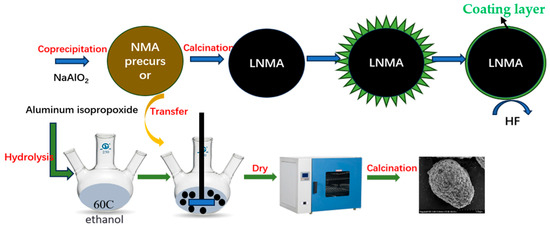
Figure 1.
Schematic diagram of the synthesis process for ultrathin Al2O3-coated LiNi0.9Mn0.05Al0.05O2 cathode.
2.3. Characterization of Materials
The crystal structure of the samples was characterized by X-ray diffraction (XRD) using a Bruker D8-Focus diffractometer (Bruker, Germany) with Cu Kα radiation. Scans were performed at a rate of 2° per minute over a 2θ range of 10° to 80°. The morphology and microstructure were examined using scanning electron microscopy (SEM; Regulus 8100) and transmission electron microscopy (TEM). The TEM measurements, including the determination of surface coating thickness, were conducted using a microscope operating at 200 kV. Elemental distribution mapping was performed using energy-dispersive X-ray spectroscopy (EDS) attached to the SEM. The bulk elemental composition was accurately analyzed by inductively coupled plasma optical emission spectrometry (ICP-OES; Agilent 5800, Agilent, Beijing, China). The specific surface area was determined by N2 adsorption–desorption analysis (BET method) using a SSA-4000 surface area analyzer (BEIJING BUILDER ELECTRONIC TECHNOLOGY CO.,LTD, Beijing, China).
2.4. Electrochemical Performance
For electrochemical performance tests, a CR2032 coin cell was used. The active material loading of the cathode was controlled to be around 2 mg/cm2 and the electrode diameter was 12 mm. The cathode slurry consisted of 80% cathode material, 10% acetylene black conductive agent, and 10% polyvinylidene fluoride (PVDF) binder fully mixed and dissolved in N-methyl pyrrolidone (NMP) solvent. Lithium metal was used as the negative electrode material. The electrolyte was 1 mol/L lithium hexafluorophosphate (LiPF6) dissolved in ethylene carbonate (EC) and dimethyl carbonate (DMC) solvents in a volume ratio (3:7). The assembly of the cells was conducted in a glove box filled with dry argon gas, ensuring water- and oxygen-free conditions in the environment.
Electrochemical testing was performed by means of a Land CT2001 automatic constant-current charge/discharge machine, which cycled between 2.7 V and 4.3 V vs. Li/Li⁺ or between 2.7 V and 4.5 V vs. Li/Li⁺ at room temperature and tested the charge/discharge capacity at various current rates (e.g., 0.1 C, 0.2 C, 0.5 C, 1 C, etc.). In addition, to evaluate the impedance characteristics of the cells, electrochemical impedance spectroscopy (EIS) measurements were performed using a Solartron eight-channel electrochemical workstation. These measurements were performed using a two-electrode configuration with an applied AC signal amplitude of 5 mV and a frequency sweep from 1 kHz to 1 MHz.
3. Results and Discussions
3.1. Structure and Morphology
The XRD patterns of all the samples are illustrated in Figure 2, where all the characteristic diffraction peaks of Figure 2 are aligned with the LiNiO2 card (PDF#09–0063), which belongs to the R-3m space group of the hexagonal α-NaFeO2 structure, and there is no crystallographic evidence for the presence of other significant characteristic diffraction peaks. The apparent splitting of the (006)/(102) and (108)/(110) bimodal peaks was observed for all cathode materials [34]. The enhanced splitting of the (006)/(102) and (108)/(110) doublets in the Al2O3-coated samples compared to the pristine sample indicates an improvement in the long-range ordering of the layered structure. Furthermore, the sharp diffraction peaks observed for both the pristine and coated samples suggest high crystallinity. Importantly, the peak sharpness was preserved (or even enhanced) after Al2O3 coating, indicating that the coating process did not detrimentally affect (and may have even slightly improved) the overall crystallinity.
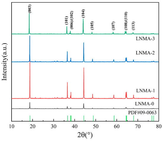
Figure 2.
XRD patterns of the LNMA-0, LNMA-1, LNMA-2, LNMA-3 cathode materials.
In the XRD analysis of layered cathode materials, the intensity ratio of the (003) peak to the (104) peak, I003/I104, is a key indicator, which directly reflects the degree of cation mixing in the material. Typically, if the I003/I104 ratio is lower than 1.2, it indicates a high degree of cation mixing within the material, which may adversely affect the electrochemical properties of the material [35]. On the contrary, higher I003/I104 ratios are usually indicative of a lower degree of cation mixing, which helps to improve the migration behavior of Li ions during charge and discharge [36]. Experimental data showed that the I003/I104 ratios of LNMA-x (x = 1–3) were all slightly increased compared to those of LNMA-0 cathode materials, which may be related to the physical and chemical structure of the coating layer [37,38]. In Table 1, the LNMA-0 sample when no coating was present had an I003/I104 of 1.24, indicating a low degree of cation mixing. In contrast, LNMA-1 prepared using an aluminum isopropoxide mass percentage of 0.5% had an increase in I003/I104 to 1.28, indicating a decrease in the degree of cationic mixing. When LNMA-2 prepared using an aluminum isopropoxide mass percentage of 1.0% was used, I003/I104 increased to 1.34, indicating a decrease in the degree of cationic mixing. However, using LNMA-3 prepared with an aluminum isopropoxide mass percentage of 1.5%, the I003/I104 peak intensity decreased to 1.27, which also reduced the degree of cationic mixing compared to the unwrapped cathode material. These results are important for optimizing the coating preparation of cathode materials and enhancing their electrochemical performance.

Table 1.
Unit cell parameters of LNMAO2 cathode materials.
The results of the Rietveld refinement of the XRD patterns are given in Figure 3, while Table 1 lists the lattice parameters obtained after Rietveld refinement of the samples. In general, the orderliness of the lamellar structure can be assessed by the c/a ratio, where a c/a ratio greater than 4.9 indicates that the material has an ordered lamellar structure [39]. The c/a ratios of all the samples in this study are greater than 4.9, which confirms that the cathode materials possess the layered structure property after the precursor has been wrapped, and this property is further verified by XRD peak analysis. The lattice parameters of the LNMA-0 sample are determined to be a = 2.8613 Å, c = 14.1842 Å, and the unit cell volume is 100.31 Å3, which is slightly larger than that of the other materials. This result (larger unit cell volume) is consistent with a consequence of the higher cation mixing in the material, as evidenced by the high Ni2+ content of 3.55% in the Li layer, considering that the radius of Ni2+ (ionic radius 0.69 Å) is smaller than that of Li⁺ (ionic radius 0.76 Å) [40]. In contrast, the relatively low value of the lattice parameter a in LNMA-2 is likely attributed to the incorporation of smaller Al3+ ions (ionic radius ~0.535 Å) into the transition metal layers during the coating process or subsequent annealing. This Al3+ doping, along with the protective effect of the coating, contributes to the stabilization of the layered structure, which is consistent with the observed reduction in cation mixing in LNMA-2 compared to LNMA-0.
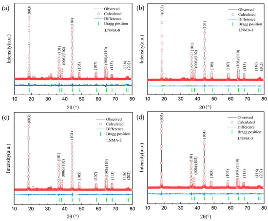
Figure 3.
The observed, calculated, and difference XRD patterns of the (a) LNMA-0, (b) LNMA-1, (c) LNMA-2, (d) LNMA-3 cathode materials calcinated at 800 °C.
In order to determine that the crystalline phase observed on the surface of LiNiMnAlO2 cathode material is Al2O3, we prepared Al2O3 particles using the same high-temperature treatment method. As shown in Figure 4, several characteristic peaks were observed in the XRD of the prepared Al2O3 powders, which can be closely matched with the characteristic diffraction peaks of the γ-Al2O3 phase (PDF No. 10–0425). In addition, no other peaks related to the impurity phase were observed. Therefore, the coating phase on the surface of LiNiMnAlO2 cathode material should be γ-Al2O3. Based on the half-peak width of the largest characteristic diffraction peak, the average size of Al2O3 nanoparticles was calculated to be 2 nm by using Scherrer’s Equation (3). The characteristic XRD peaks of Al2O3-coating layer were not observed in the XRD spectra of Al2O3-covered LiNiMnAlO2 cathode particles. This is because the XRD peaks of Al2O3 nanoparticles on the surface of the particles are very broad and the particle sizes are tiny compared to the XRD spectra of cathode material, so they are expected to be covered by the background of the XRD spectra of cathode material, and cannot be captured simultaneously.
where, D is crystallite size (nm); K is Scherrer constant, typically 0.9 for simplified calculations; λ is X-ray wavelength (e.g., Cu-Kα: 0.15418 nm); β is Full Width at Half Maximum (FWHM) of the diffraction peak θ and Bragg angle corresponding to the diffraction peak.
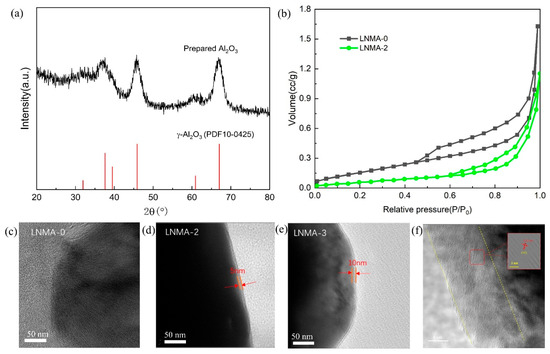
Figure 4.
(a) X-ray diffraction pattern of the prepared Al2O3 nanoparticles after heat treatment at 800 °C for 12 h. (b) Nitrogen adsorption–desorption isotherm of LNMA-0 and LNMA-2, TEM images of cathode (c) LNMA-0, (d) LNMA-2, (e) LNMA-3, and lattice fringes of coating in (f) LNMA-3.
Table 2 details the elemental composition of the cathode materials determined by ICP-MS. The analysis results show that the contents of Ni, Mn, and Al are about 0.9, 0.05, and 0.05, respectively, and the actual chemical compositions and the theoretically calculated nominal compositions are within acceptable experimental errors, which indicates that the expected phase compositions have been formed, and it can also be found that the relative amount of Al content increases slightly with the increase in the amount of aluminum isopropoxide, which proves the successful introduction of the Al2O3-coating layer. The chemical composition of these cathode materials after normalization can be expressed as Li1.05Ni0.9Mn0.05Al0.05O2. The lithium content is lower than the theoretical design value mainly due to the volatility of lithium during high-temperature calcination [41].
Table 2.
The chemical composition of ICP-OES for LNMA cathode materials.
The elemental distributions on the surface of LNMA-0, LNMA-1, LNMA-2, and LNMA-3 cathode materials were analyzed by scanning electron microscopy coupled with energy dispersive X-ray spectroscopy (SEM-EDS) as shown in Figure 5. From the elemental mapping, the distribution of three elements, Ni, Mn, and Al, can be observed in all LNMA samples. The results show that Ni, Mn, and Al can be uniformly distributed on the surface of the LNMA samples, which further deduces that these elements are well dispersed in the material, but it is difficult to observe that there is an inclusions layer on the surface, which needs to be analyzed in depth in conjunction with transmission electron microscopy.
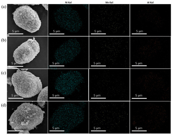
Figure 5.
EDS mapping of cathode of (a) LNMA-0, (b) LNMA-1, (c) LNMA-2, (d) LNMA-3.
Figure 4b presents the nitrogen adsorption–desorption isotherms of the pristine LNMA-0 cathode material and the precursor-coated LNMA-2 cathode material. The specific surface area of LNMA-0 was found to be 0.870 m2 g−1, which is much higher than that of the cathode material LNMA-2 synthesized by encapsulation of the precursor (0.456 m2 g−1). This is due to the fact that the Al2O3 surface coating leads to a reduction in the specific surface area of the cathode material, and this reduction isolates the electrolyte from contact with the cathode material, and therefore in turn has an impact on the electrochemical performance.
In order to further confirm the successful formation of surface coating on the surface of Ni-Mn-Al cathode materials, as well as to gain insights into the thickness and homogeneity of the inclusions, we performed transmission electron microscopy (TEM) image analysis on pure samples of LNMA-0 and cathode materials synthesized with a 1% mass ratio and 1.5% isopropanol (LNMA-2 and LNMA-3) (Figure 4c–e). In the cathode material LNMA-0, we did not find any surface material around it, while on the surface of LNMA-2 and LNMA-3 cathode materials, the thickness of the inclusions were found to be 5 nm and 10 nm, respectively, which indicated that there was a significant difference in the thickness of the two coatings. To further determine the composition of the encapsulated structure, the lattice fringes of the coating layer were analyzed using transmission electron microscopy (TEM) in Figure 4f. The study revealed an interplanar spacing of approximately 0.10 nm, which can be attributed to the characteristic (440) diffraction plane of γ-Al2O3. Thus, it is confirmed that the coating layer consists of γ-Al2O3. Based on these results, we can conclude that Al2O3 can be uniformly deposited as a thin layer on the surface of the spheres of the nickel-manganese-aluminum cathode materials by using aluminum isopropoxide to control the surface precipitation of the precursors. It can act as a protective barrier to stabilize the electrode/electrolyte interface in the electrochemical performance of the material.
3.2. Electrochemical Performance
Figure 6a shows the initial charge/discharge curves of the samples at 0.2 C in 2.7–4.3 V. The charge/discharge voltage curves of all the samples are similar to those of the nickel-rich cathode materials, but the initial charge/discharge capacities are different. As shown in Figure 8a, the voltage profiles of all samples have a distinct oxidation peak at 3.9 V and a smaller reduction peak at 3.7 V. These peaks correspond to the Ni2+/Ni4+ redox pairs [42]. The initial charge capacities of LNMA-0 to LNMA-3 cathodes were determined as 199.4, 201.7, 204.5, and 203.7 mAh g−1, with corresponding discharge capacities of 187.1, 190.2, 193.5, and 191.7 mAh g−1, respectively. These values yield Coulombic efficiencies of 93.8%, 94.3%, 94.6%, and 94.1%. The results showed that the charging and discharging capabilities of LNMA cathode materials were first enhanced and then weakened with the increase in the amount of aluminum isopropoxide in the synthesis process. The increase in the specific capacity is related to the mixing and discharging degree of Li+/Ni2+ in the cathode material. At the same time, this characteristic parameter is not a decisive factor for the charge/discharge performance, and the migration path of lithium ions in the particles also affects the discharge process. Thick surface coatings also reduce the amount of active material to a certain extent, and therefore are not conducive to performance improvement.
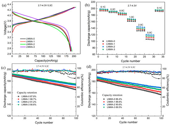
Figure 6.
The electrochemical performance of LNMA-x cathode active materials, including (a) initial charge/discharge profiles at 0.2 C, (b) different rate capability, and (c) cycling stability tested at 0.2 C and (d) 0.5 C, all measured within a voltage range of 2.7–4.3 V at room temperature.
The rate performance of the prepared cathode materials is shown in Figure 6b. The specific capacity of LNMA-2 is as high as 120.5 mAh g−1 at 5 C, while that of LNMA-0 is only 106.2 mAh g−1, and LNMA-2 performs the best at different charging and discharging multiplicities. As shown in Figure 4, all samples have similar particle size after surface roasting. Therefore, the diffusion distance of lithium ions is also not affected by the particles. However, as shown in Table 3, the surface coating on the cathode may affect the charge transfer resistance and diffusion rate of lithium ions. Therefore, we believe that the rate performance of LNMA cathode materials was related with the diffusion rate of lithium ions. The faster the diffusion rate of lithium ions, the higher rate performance of LNMA cathode. At the same time, the surface coating layer can reduce the contact between electrolyte and cathode material, effectively reduce the occurrence of surface side reactions, and does not affect the conductivity of Li ions.
Table 3.
Rs, Rct, and Li diffusion parameters of as-prepared LNMA.
The cycling stability of the samples measured at rates of 0.2 C and 0.5 C within the voltage window of 2.7–4.3 V is shown in Figure 6c,d. After 100 cycles, the capacity retention of LNMA-0, LNMA-1, LNMA-2, and LNMA-3 were 87.8%, 88.7%, 91.2%, and 90.6% at 0.2 C, and 86.4%, 88.6%, 90.6%, and 89.5% at 0.5 C, respectively. Therefore, the cycling stability of the pristine cathode material LNMA-0 was enhanced by the introduction of an Al2O3 surface layer. This layer functions as a physical barrier to reduce the direct contact between the cathode material and the electrolyte, thus inhibiting side reactions such as electrolyte decomposition and dissolution of transition metal ions. In addition, the layer acts as a buffer layer for volume changes, reducing particle rupture, maintaining structural integrity, and enhancing cycling stability. The aluminum contained in the layer material enhances the structural stability of the material surface in two ways. Firstly, it reduces cation mixing. Second, it has higher Al-O bonding energy than Ni-O bonding energy, which reduces the occurrence of phase transitions. Therefore, this surface structure is very important for the cycling performance of the cathode material. This means that the thickness of Al2O3 can have a great impact on the internal properties of LNMAO2, and therefore the thickness of alumina needs to be optimized in order to ensure the transport of lithium ions at the electrode/electrolyte interface.
Figure 7 comprehensively evaluates the electrochemical performance of LNMA cathode materials within the voltage range of 2.7–4.5 V. Figure 7a displays the initial charge/discharge profiles at 0.5 C, where LNMA-2 exhibits capacities of 203.68 and 198.12 mAhg−1 with a Coulombic efficiency (CE) of 97.3%, significantly outperforming LNMA-0 (196.1/189.2 mAhg−1, CE = 96.4%). This enhancement demonstrates the efficacy of Al2O3 coating in improving charge retention. Rate capability analysis (Figure 7b) reveals superior performance for coated samples: LNMA-2 delivers discharge capacities of 216.4 (0.1 C), 205.6 (0.2 C), 197.1 (0.5 C), 182.5 (1 C), 165.2 (2 C), and 132.1 mAhg−1 (5 C), compared to LNMA-0’s 210.5, 200.8, 189.7, 154.4, 118.8, and 102.1 mAhg−1. Both LNMA-1 and LNMA-3 also surpass LNMA-0, indicating a clear coating-dependent enhancement. Long-term cycling stability (Figure 7c) further validates this trend. After 100 cycles at 0.2 C, capacity retentions for LNMA-0 to LNMA-3 are 86.3%, 87.6%, 88.4%, and 86.8%, respectively. At 0.5 C, corresponding values are 84.7%, 86.1%, 88.3%, and 87.4%. Similarly, this electrochemical performance improvement may be attributed to the fact that the introduction of the coating layer facilitates the formation of a gradient distribution of Al within the cathode material, which reduces Li+/Ni2+ mixing, and also the coating layer forms a nanoscale protective layer on the surface of the material, and thus the modified cathode material also improves the cycling stability at 2.7–4.5 V.
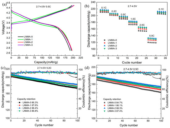
Figure 7.
The electrochemical performance of LNMA cathode active materials, including (a) initial charge/discharge profiles at 0.5 C, (b) rate capability, and (c) cycling stability tested at 0.2 C and (d) 0.5 C, all measured within a voltage range of 2.7–4.5 V at room temperature.
In order to study the evolution of the voltage profile during cycling, we analyzed the capacity difference (dQ/dV) profiles of LNMA-0 and LNMA-2 for the 1st, 10th, 20th, and 50th cycles at 0.5 C in the voltage range 2.7–4.3 V. For LNMA-0 (Figure 8a), the cathodic peak (corresponding to the Ni2+/Ni4+ redox pair) gradually shifted from 3.85 V to 3.87 V during cycling. Meanwhile, the anodic peak (corresponding to the Ni4+/Ni2+ redox pair) gradually shifted from about 3.71 V to 3.69 V. Compared with LNMA-2 (Figure 8b), the peak position of LNMA-2 remained essentially unchanged during the cycling process, and this significant voltage shift suggests that LNMA-0 underwent a larger electrochemical polarization during the cycling process. In addition, the anodic peak observed at 3.86 V weakened in intensity after the 50th cycle, which could be attributed to the degradation of the electrode/electrolyte interface and the occurrence of some side reactions. In contrast, the anodic peak of LNMA-2 (Figure 8b) shifted very little, indicating less electrochemical polarisation and also reflecting the excellent cycling stability mentioned above. The improved cycling stability is mainly attributed to the protective effect of the Al2O3-capping layer.
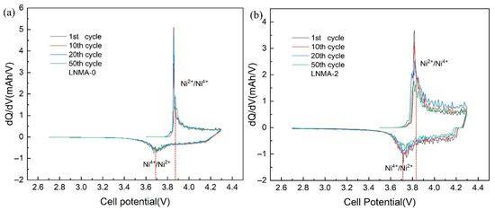
Figure 8.
The differential capacity (dQ/dV) of (a) LNMA-0 and (b) LNMA-2 in 2.7–4.3 V at 0.5 C cycling.
In order to systematically evaluate the electrochemical performance of the different cathode materials, we used the electrochemical impedance spectroscopy (EIS) technique for detailed analysis. As shown in Figure 9a, the impedance spectra of all NMA cathode materials show a tendency of a semicircular region followed by a diagonal line, which is consistent with a typical electrochemical reaction process. In order to resolve these data more accurately and reveal the physical meaning behind them, we constructed an equivalent circuit model to describe the electrochemical behavior of the whole system. This model not only covers the complex kinetic processes occurring from the macroscopic electrochemical cell level to the microscopic individual cell internals, but also provides a theoretical basis for understanding the differences in electrochemical properties among different LNMA-x cathode materials.
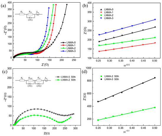
Figure 9.
(a) Nyquist plots of as-prepared LNMA electrodes; (b) the relationships between Z′ and of as-prepared LNMA electrodes; (c) Nyquist plots of LNMA electrodes after 50th cycling; (d) the relationships between Z′ and after 50th cycling.
Among the aforementioned, represents the electrolyte resistance, which is a measure of the solution’s conductivity; denotes the charge transfer resistance that occurs at the electrode/electrolyte interface, which reflects the kinetic barriers in the electron transfer process, which is usually highly correlated with the activation energy or energy barriers of the reaction; CPE is used to simulate the double-layer capacitance and other non-ideal capacitance effects; and Ws corresponds to the Warburg diffusion impedance, which part mainly reflects the resistance encountered by Li-ion diffusion within the cathode material [43]. In addition, by analyzing the lithium ion diffusion coefficient D, the kinetic properties of the cathode material can be further explored, which can be obtained by the following equation [44]:
where R denotes the gas constant, T is the absolute temperature, A refers to the effective surface area of the electrode, F is Faraday’s constant, C is the molar concentration of lithium ions (1 mol/L), ω is a coefficient related to the frequency of measurement, and σ can be obtained from the slope of Figure 9b. The results of the relevant calculations are shown in Table 3, and it is found that the of LNMA-x (x = 0–4) are 2.31, 1.78, 2.24, and 1.96 Ω, respectively, which is attributed to the fact that the resistances of electrolyte solutions are basically the same. With the increase in the Al2O3 surface, the diffusion rate of lithium ions increases from 3.23 × 10⁻¹¹ cm2 s−1 to 3.95 × 10⁻¹⁰ cm2 s−1. Meanwhile, the values are 157.6, 123.4, 114.1, and 116.4 Ω, respectively. The higher values are related to the thickness of the Al2O3 coating. This suggests that γ-Al2O3 is an efficient coating material that favors lithium migration and it does not detract from the fact that it can improve the cycling stability of the electrode material as well as the rate performance. In addition, after 50 cycles, the of the LNMA-0 and LNMA-2 change is small. The of the LNMA-0-positive electrode becomes 273.1 Ω in the fully discharged state, while the of the LNMA-2-positive electrode is 204.3 Ω, which indicates that the values of both electrodes increase after cycling, and the of the LNMA-2 is comparatively smaller. However, the of LNMA-0 and LNMA-2 are 11.64 Ω and 8.37 Ω in Table 4, respectively.
Table 4.
Rs, RCEI, Rct and Li diffusion parameters of LNMA after cycling.
Table 5 presents a comparative analysis of relevant studies in recent years. The solvothermal method employed in this study effectively overcomes the high cost limitations of conventional atomic layer deposition (ALD). By encapsulating precursors via solvothermal synthesis at 60 °C, this approach not only addresses the stringent temperature requirements typically associated with conventional processes (80–120 °C) but also eliminates the need for secondary calcination of the cathode material. The resulting cathode material features an encapsulation layer with a thickness of 0–10 nm, while maintaining uniform coating integrity. Electrochemical performance tests conducted at 2.7–4.3 V 0.2 C and 0.5 C demonstrate that the cycling stability of the cathode material improves from 85.5% to 91.2% and 90.6% after 100 cycles.
Table 5.
Comparison of Al2O3-coating performance for different cathodes.
In this work, we synthesized a continuous and ultrathin γ-Al2O3 coating at the cathode material interface. Figure 10 illustrates the working mechanism of the γ-Al2O3-coating layer. This γ-Al2O3 layer protects the bulk material from direct electrolyte corrosion, thereby suppressing transition metal dissolution, while simultaneously enabling rapid diffusion pathways for both electrons and Li⁺ ions. Furthermore, unlike conventional coatings confined to particle surfaces, the γ-Al2O3 integrated into the host structure stabilizes the lattice framework and buffers volume variations between the core and shell during lithiation/delithiation processes, thereby enhancing the cycling stability of the cathode material.
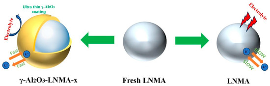
Figure 10.
Schematic illustrations of γ-Al2O3-embedded LNMA and protective coating to suppress side reactions.
4. Conclusions
By using an encapsulation synthesis method for the precursors, we successfully prepared nano-ultrathin Al2O3-encapsulated LiNi0.9Mn0.05Al0.05O2 composite cathode materials. This cathode material demonstrated relatively higher charge/discharge capacities (203.68 mAh/g and 198.12 mAh/g) significantly enhanced cycling stability (88.3% retention at 0.5 C for 100 cycles) and rate performance under different cutoff voltage conditions such as at 2.7–4.5 V, with significant performance enhancement over the untreated original samples. These improvements are mainly attributed to the formation of an ultrathin protective film on the surface, which mitigates the erosion of the cathode material by the electrolyte during charging and discharging. Therefore, the uniform and ultrathin 5 nm Al2O3-wrapped LiNi0.9Mn0.05Al0.05O2 composites show great potential as high-performance cathode materials for Li-ion batteries. In addition, the present experimental method is also expected to provide new ideas for the design and synthesis of other advanced material structures.
Author Contributions
Conceptualization, F.L., R.W. and A.W.; methodology, F.L. and R.W.; software, F.L., C.W., N.Y. and Z.X.; validation, F.L. and A.W.; formal analysis, F.L., C.W., N.Y. and Z.X.; investigation, F.L.; resources, R.W. and A.W.; data curation, F.L., N.Y. and Z.X.; writing—original draft preparation, F.L. and C.W.; writing—review and editing, F.L., C.W., N.Y., Z.X. and A.W.; visualization, F.L.; supervision, R.W. and A.W.; project administration, R.W. and A.W.; funding acquisition, A.W. All authors have read and agreed to the published version of the manuscript.
Funding
This work was supported by the National Natural Science Foundation of China (No. 22278308); Beijing-Tianjin-Hebei Basic Research Cooperation Special Project (No. B2024209048); and Natural Science Foundation of Tianjin, China (Grant No. 24JCZXJC00250).
Data Availability Statement
The original contributions presented in this study are included in the article. Further inquiries can be directed to the corresponding authors.
Conflicts of Interest
The authors declare no conflict of interest.
References
- Ni, L.; Chen, H.; Gao, J.; Mei, Y.; Wang, H.; Zhu, F.; Ji, X. Multiscale crystal field effect for high-performance ultrahigh-Ni layered cathode. ACS Nano 2023, 17, 12759–12773. [Google Scholar] [CrossRef] [PubMed]
- Kim, J.; Lee, H.; Cha, H.; Yoon, M.; Park, M.; Cho, J. Prospect and reality of Ni-rich cathode for commercialization. Adv. Energy Mater. 2018, 8, 1702028. [Google Scholar] [CrossRef]
- Cui, L.F.; Yang, Y.; Hsu, C.M.; Cui, Y. Carbon−silicon core−shell nanowires as high capacity electrode for lithiumion batteries. Nano Lett. 2009, 9, 3370–3374. [Google Scholar] [CrossRef]
- Whittingham, M.S. History, evolution, and future status of energy storage; (Special Centennial Issue). Proc. IEEE 2012, 100, 1518–1534. [Google Scholar] [CrossRef]
- Tarascon, J.M.; Armand, M. Issues and challenges facing rechargeable lithium batteries. Nature 2001, 414, 359–367. [Google Scholar] [CrossRef] [PubMed]
- Wang, C.; Liu, Z.; Liu, F.; Wang, A.; Wang, R. High-Nickel NMA Cathode: Glycerol-Modulated Coprecipitation Preparation and an Insight into Inheritance Relationship. ACS Appl. Energy Mater. 2024, 7, 10238–10244. [Google Scholar] [CrossRef]
- Li, W.; Lee, S.; Manthiram, A. High-nickel NMA: A cobalt-free alternative to NMC and NCA cathodes for lithium-ion batteries. Adv. Mater. 2020, 32, 2002718. [Google Scholar] [CrossRef]
- Kan, H.; Yang, Z.; Meng, Q.; Dong, P.; Zhang, Y. Preparation and Electrochemical Performance of the Ni-Rich Co-Free Cathode Material LiNi0.94Mn0.04Al0.02O2. Energy Fuels 2024, 38, 6420–6426. [Google Scholar] [CrossRef]
- Li, W.; Erickson, E.M.; Manthiram, A. High-nickel layered oxide cathodes for lithium-based automotive batteries. Nat. Energy 2020, 5, 26–34. [Google Scholar] [CrossRef]
- Manthiram, A. A reflection on lithium-ion battery cathode chemistry. Nat. Commun. 2020, 11, 1550. [Google Scholar] [CrossRef]
- Lee, S.; Kmiec, S.; Manthiram, A. Effects of Coprecipitation Conditions on the Electrochemical Properties of Cobalt-Free LiNi0.9Mn0.1−xAlxO2 Cathodes. Small 2024, 20, 2406947. [Google Scholar] [CrossRef]
- Li, W.; Song, B.; Manthiram, A. High-voltage positive electrode materials for lithiumion batteries. Chem. Soc. Rev. 2017, 46, 3006–3059. [Google Scholar] [CrossRef]
- Fan, X.; Wang, C. High-voltage liquid electrolytes for Li batteries: Progress and perspectives. Chem. Soc. Rev. 2021, 50, 10486–10566. [Google Scholar] [CrossRef] [PubMed]
- Su, L.; Jarvis, K.; Charalambous, H.; Dolocan, A.; Manthiram, A. Stabilizing High-Nickel Cathodes with High-Voltage Electrolytes. Adv. Funct. Mater. 2023, 33, 2213675. [Google Scholar] [CrossRef]
- Yu, L.; Liu, T.; Amine, R.; Wen, J.; Lu, J.; Amine, K. High nickel and no cobalt─the pursuit of next-generation layered oxide cathodes. ACS Appl. Mater. Interfaces 2022, 14, 23056–23065. [Google Scholar] [CrossRef]
- Ni, L.; Chen, H.; Gao, J.; Mei, Y.; Wang, H.; Zhu, F.; Ji, X. Calcium-induced pinning effect for high-performance Co-free Ni-rich NMA layered cathode. Nano Energy 2023, 115, 108743. [Google Scholar] [CrossRef]
- Yan, J.; Yang, Z.; Kan, H.; Zha, Y.; Li, C.; Meng, Q.; Zhang, Y. Microstructure and electrochemical properties of Mg/Nb/Zr co-doped LiNi0.94Mn0.04Al0.02O2 cathode materials. Ceram. Int. 2024, 50, 24872–24880. [Google Scholar] [CrossRef]
- Yan, W.; Yang, S.; Huang, Y.; Yang, Y.; Yuan, G. A review on doping/coating of nickel-rich cathode materials for lithium-ion batteries. J. Alloys Compd. 2020, 819, 153048. [Google Scholar] [CrossRef]
- Oh, P.; Yun, J.; Park, S.; Nam, G.; Liu, M.; Cho, J. Recent advances and prospects of atomic substitution on layered positive materials for lithiumion battery. Adv. Energy Mater. 2021, 11, 2003197. [Google Scholar] [CrossRef]
- Guan, P.; Zhou, L.; Yu, Z.; Sun, Y.; Liu, Y.; Wu, F.; Chu, D. Recent progress of surface coating on cathode materials for high-performance lithium-ion batteries. J. Energy Chem. 2020, 43, 220–235. [Google Scholar] [CrossRef]
- Kalluri, S.; Yoon, M.; Jo, M.; Park, S.; Myeong, S.; Kim, J.; Cho, J. Surface engineering strategies of layered LiCoO2 cathode material to realize high-energy and high-voltage Li-ion cells. Adv. Energy Mater. 2017, 7, 1601507. [Google Scholar] [CrossRef]
- Kuenzel, M.; Kim, G.T.; Zarrabeitia, M.; Lin, S.D.; Schuer, A.R.; Geiger, D.; Passerini, S. Crystal engineering of TMPOx-coated LiNi0.5Mn1.5O4 cathodes for high-performance lithium-ion batteries. Mater. Today 2020, 39, 127–136. [Google Scholar] [CrossRef]
- Nisar, U.; Amin, R.; Essehli, R.; Shakoor, R.A.; Kahraman, R.; Kim, D.K.; Belharouak, I. Extreme fast charging characteristics of zirconia modified LiNi0.5Mn1.5O4 cathode for lithiumion batteries. J. Power Sources 2018, 396, 774–781. [Google Scholar] [CrossRef]
- Fu, L.J.; Liu, H.; Li, C.; Wu, Y.P.; Rahm, E.; Holze, R.; Wu, H.Q. Surface modifications of electrode materials for lithiumion batteries. Solid State Sci. 2006, 8, 113–128. [Google Scholar] [CrossRef]
- Jeong, H.Y.; Jung, Y.H.; Seok, D.C.; Yoo, S.; Kwon, S.K.; Han, D. Surface cleaning effect of NCM powder and improvement of lithiumion battery on the thermal stability and life cycle employing dielectric barrier discharge technique. Curr. Appl. Phys. 2018, 18, 961–967. [Google Scholar] [CrossRef]
- Nisar, U.; Al-Hail SA, J.; Petla, R.K.; Shakoor, R.A.; Essehli, R.; Kahraman, R.; Amin, M.R. Understanding the origin of the ultrahigh rate performance of a SiO2-modified LiNi0.5Mn1.5O4 cathode for lithium-ion batteries. ACS Appl. Energy Mater. 2019, 2, 7263–7271. [Google Scholar] [CrossRef]
- Brow, R.; Donakowski, A.; Mesnier, A.; Pereira, D.J.; Steirer, K.X.; Santhanagopalan, S.; Manthiram, A. Mechanical pulverization of Co-free nickel-rich cathodes for improved high-voltage cycling of lithium-ion batteries. ACS Appl. Energy Mater. 2022, 5, 6996–7005. [Google Scholar] [CrossRef]
- Gao, T.; Tian, P.; Xu, Q.; Pang, H.; Ye, J.; Ning, G. Coating effect of various-phase alumina nanoparticles on NCM811 cathode for enhancing electrochemical performance of lithium-ion batteries. ACS Appl. Energy Mater. 2024, 7, 3904–3915. [Google Scholar] [CrossRef]
- Oh, S.; Lee, J.K.; Byun, D.; Cho, W.I.; Cho, B.W. Effect of Al2O3 coating on electrochemical performance of LiCoO2 as cathode materials for secondary lithium batteries. J. Power Sources 2004, 132, 249–255. [Google Scholar] [CrossRef]
- Cho, J.; Kim, Y.J.; Park, B. Novel LiCoO2 cathode material with Al2O3 coating for a Li ion cell. Chem. Mater. 2000, 12, 3788–3791. [Google Scholar] [CrossRef]
- Kim, Y.; Kim, H.S.; Martin, S.W. Synthesis and electrochemical characteristics of Al2O3-coated LiNi1/3Co1/3Mn1/3O2 cathode materials for lithium ion batteries. Electrochim. Acta 2006, 52, 1316–1322. [Google Scholar] [CrossRef]
- Li, L.; Chen, Z.; Zhang, Q.; Xu, M.; Zhou, X.; Zhang, K. A hydrolysis-hydrothermal route for the synthesis of ultrathin LiAlO2-inlaid LiNi0.5Co0.2Mn0.3O2 as a high-performance cathode material for lithium ion batteries. J. Mater. Chem. A 2015, 3, 894–904. [Google Scholar] [CrossRef]
- Wefers, K.; Misra, C. Oxides and Hydroxides of Aluminum; Alcoa Laboratories: Pittsburgh, PA, USA, 1987; Volume 19. [Google Scholar]
- Jeong, M.; Kim, H.; Lee, W.; Ahn, S.J.; Lee, E.; Yoon, W.S. Stabilizing effects of Al-doping on Ni-rich LiNi0.80Co0.15Mn0.05O2 cathode for Li rechargeable batteries. J. Power Sources 2020, 474, 228592. [Google Scholar] [CrossRef]
- Yang, K.; Fan, L.Z.; Guo, J.; Qu, X. Significant improvement of electrochemical properties of AlF3-coated LiNi0.5Co0.2Mn0.3O2 cathode materials. Electrochim. Acta 2012, 63, 363–368. [Google Scholar] [CrossRef]
- Li, L.; Li, X.H.; Wang, Z.X.; Guo, H.J.; Yue, P.; Chen, W.; Wu, L. A simple and effective method to synthesize layered LiNi0.8Co0.1Mn0.1O2 cathode materials for lithium ion battery. Powder Technol. 2011, 206, 353–357. [Google Scholar] [CrossRef]
- Ma, Q.; Peng, F.; Li, R.; Yin, S.; Dai, C. Effect of calcination temperature on microstructure and electrochemical performance of lithium-rich layered oxide cathode materials. Mater. Sci. Eng. B 2016, 213, 123–130. [Google Scholar] [CrossRef]
- Wang, Z.; Xu, P.; Yue, X.; Wang, A.; Wu, Y.; Liu, X.; Zhang, Y. Effect of calcination temperature on the electrochemical performance of nickel nanoparticles on carbon coated porous silicon nanospheres anode for lithium-ion batteries. Colloids Surf. A: Physicochem. Eng. Asp. 2022, 648, 129193. [Google Scholar] [CrossRef]
- Kim, J.H.; Park, C.W.; Sun, Y.K. Synthesis and electrochemical behavior of Li0.1Ni0.35−x/2CoxMn0.55−x/2O2 cathode materials. Solid State Ion. 2003, 164, 43–49. [Google Scholar] [CrossRef]
- Hong, Y.; Park, Y.J.; Ryu, K.S.; Chang, S.H. Charge/discharge behavior of LiNi0.20Li0.20Mn0.60O2 and LiCo0.20Li0.27Mn0.53O2 cathode materials in lithium secondary batteries. Solid State Ion. 2005, 176, 1035–1042. [Google Scholar] [CrossRef]
- Su, Y.; Li, L.; Chen, G.; Chen, L.; Li, N.; Lu, Y.; Wu, F. Strategies of removing residual lithium compounds on the surface of Ni-rich cathode materials. Chin. J. Chem. 2021, 39, 189–198. [Google Scholar] [CrossRef]
- Shepard, R.; Brennan, S.; Juran, T.R.; Young, J.; Smeu, M. Ab initio determination of a simultaneous dual-ion charging mechanism for Ni0.25Mn0.75O2 through redox reactions of Ni2+/Ni4+ and O2−/O−. J. Mater. Chem. A 2022, 10, 18916–18927. [Google Scholar] [CrossRef]
- Magar, H.S.; Hassan, R.Y.; Mulchandani, A. Electrochemical impedance spectroscopy (EIS): Principles, construction, and biosensing applications. Sensors 2021, 21, 6578. [Google Scholar] [CrossRef] [PubMed]
- Qian, D.; Gu, Y.; Chen, Y.; Liu, H.; Wang, J.; Zhou, H. Ultra-high specific capacity of Cr3+-doped Li4Ti5O12 at 1.55 V as anode material for lithium-ion batteries. Mater. Lett. 2019, 238, 102–106. [Google Scholar] [CrossRef]
- Shi, Y.; Zhang, M.; Qian, D.; Meng, Y.S. Ultrathin Al2O3 coatings for improved cycling performance and thermal stability of LiNi0.5Co0.2Mn0.3O2 cathode material. Electrochim. Acta 2016, 203, 154–161. [Google Scholar] [CrossRef]
- Dong, S.; Zhou, Y.; Hai, C.; Zeng, J.; Sun, Y.; Ma, Y.; Wu, Z. Enhanced cathode performance: Mixed Al2O3 and LiAlO2 coating of Li1.2Ni0.13Co0.13Mn0.54O2. ACS Appl. Mater. Interfaces 2020, 12, 38153–38162. [Google Scholar] [CrossRef]
- Cao, G.; Jin, Z.; Zhu, J.; Li, Y.; Xu, B.; Xiong, Y.; Yang, J. A green Al2O3 metal oxide coating method for LiNi0.5Co0.2Mn0.3O2 cathode material to improve the high voltage performance. J. Alloys Compd. 2020, 832, 153788. [Google Scholar] [CrossRef]
- Zhu, W.; Huang, X.; Liu, T.; Xie, Z.; Wang, Y.; Tian, K.; Zhao, J. Ultrathin Al2O3 coating on LiNi0.8Co0.1Mn0.1O2 cathode material for enhanced cycleability at extended voltage ranges. Coatings 2019, 9, 92. [Google Scholar] [CrossRef]
- Feng, Y.; Xu, H.; Wang, B.; Wang, S.; Ai, L.; Li, S. Enhanced electrochemical performance of LiNi0.8Co0.1Mn0.1O2 cathode materials by Al2O3 coating. J. Electrochem. Energy Convers. Storage 2021, 18, 31005. [Google Scholar] [CrossRef]
- Lee, Y.; Shin, W.K.; Kannan, A.G.; Koo, S.M.; Kim, D.W. Improvement of the cycling performance and thermal stability of lithium-ion cells by double-layer coating of cathode materials with Al2O3 nanoparticles and conductive polymer. ACS Appl. Mater. Interfaces 2015, 7, 13944–13951. [Google Scholar] [CrossRef] [PubMed]
Disclaimer/Publisher’s Note: The statements, opinions and data contained in all publications are solely those of the individual author(s) and contributor(s) and not of MDPI and/or the editor(s). MDPI and/or the editor(s) disclaim responsibility for any injury to people or property resulting from any ideas, methods, instructions or products referred to in the content. |
© 2025 by the authors. Licensee MDPI, Basel, Switzerland. This article is an open access article distributed under the terms and conditions of the Creative Commons Attribution (CC BY) license (https://creativecommons.org/licenses/by/4.0/).