Review

A Review of Heat Transfer and Numerical Modeling for Scrap Melting in Steelmaking Converters

by
Mohammed B. A. Hassan
1,*,
Florian Charruault
2,†,
Bapin Rout
2,†,
Frank N. H. Schrama
1,2,†,
Johannes A. M. Kuipers
3,† and
Yongxiang Yang
1,†
1
Department of Materials Science and Engineering, Delft University of Technology, 2628 CD Delft, The Netherlands
2
Tata Steel Netherlands, 1970 CA IJmuiden, The Netherlands
3
Department of Chemical Engineering and Chemistry, Eindhoven University of Technology, 5612 AZ Eindhoven, The Netherlands
*
Author to whom correspondence should be addressed.
These authors contributed equally to this work.
Metals 2025, 15(8), 866; https://doi.org/10.3390/met15080866 (registering DOI)
Submission received: 17 June 2025 / Revised: 27 July 2025 / Accepted: 28 July 2025 / Published: 1 August 2025

Abstract

Steel is an important product in many engineering sectors; however, steelmaking remains one of the largest CO 2 emitters. Therefore, new governmental policies drive the steelmaking industry toward a cleaner and more sustainable operation such as the gas-based direct reduction–electric arc furnace process. To become carbon neutral, utilizing more scrap is one of the feasible solutions to achieve this goal. Addressing knowledge gaps regarding scrap heterogeneity (size, shape, and composition) is essential to evaluate the effects of increased scrap ratios in basic oxygen furnace (BOF) operations. This review systematically examines heat and mass transfer correlations relevant to scrap melting in BOF steelmaking, with a focus on low Prandtl number fluids (thick thermal boundary layer) and dense particulate systems. Notably, a majority of these correlations are designed for fluids with high Prandtl numbers. Even for the ones tailored for low Prandtl, they lack the introduction of the porosity effect which alters the melting behavior in such high temperature systems. The review is divided into two parts. First, it surveys heat transfer correlations for single elements (rods, spheres, and prisms) under natural and forced convection, emphasizing their role in predicting melting rates and estimating maximum shell size. Second, it introduces three numerical modeling approaches, highlighting that the computational fluid dynamics–discrete element method (CFD–DEM) offers flexibility in modeling diverse scrap geometries and contact interactions while being computationally less demanding than particle-resolved direct numerical simulation (PR-DNS). Nevertheless, the review identifies a critical gap: no current CFD–DEM framework simultaneously captures shell formation (particle growth) and non-isotropic scrap melting (particle shrinkage), underscoring the need for improved multiphase models to enhance BOF operation.

Graphical Abstract

1. Introduction

Global steel production has increased significantly over the past decades. In 2023, the total crude steel production reached 1888.2 Mt [1], with approximately 70% produced via the blast furnace (BF)–basic oxygen furnace (BOF) route. The BF–BOF route is associated with high CO 2 emissions, averaging approximately 2 tons of CO 2 per ton of steel, which is nearly four times greater than the emissions from electric arc furnace (EAF) production [1].
To achieve circularity and net-zero emissions, direct reduced iron (DRI)-based technologies, increasingly adapted for hydrogen utilization, are expected to play a critical role. Steel scrap, due to its relatively low carbon footprint, represents another key pathway to reduce CO 2 emissions. Scrap is used both as a partial ferrous input in BOF and as the sole feedstock in EAF. However, scrap utilization in BOF is constrained by two primary challenges: (i) the risk of introducing tramp elements that may degrade the final steel quality, and (ii) the lack of an external energy source to melt the scrap, which limits the scrap fraction.
This study provides a systematic review of heat and mass transfer correlations relevant to scrap melting in BOF steelmaking, with emphasis on correlations applicable to low-Prandtl-number fluids (characterized by thick thermal boundary layers) and dense particulate systems. The potential of employing mathematical formulations derived from high-fidelity simulations to model large-scale industrial BOF processes is also discussed.
This review addresses three core areas to guide researchers and practitioners. First, the BOF heat cycle, underlying transport phenomena, associated dimensionless numbers, and modeling challenges are described. Second, existing heat and mass transfer correlations for natural and forced convection are compiled and evaluated, including the influence of scrap bed porosity (solid fraction) on transport coefficients. Finally, different modeling strategies are reviewed, including particle-resolved direct numerical simulation (PR-DNS) and computational fluid dynamics coupled with the discrete element method (CFD-DEM), with particular focus on bridging spatial scales by importing correlations from experiments or PR-DNS into CFD-DEM frameworks.

1.1. The BOF Heat Cycle

The BOF heat cycle is planned according to the target steel grade and the quality and composition of the hot metal and scrap. The process begins with the charging of scrap of various sizes and types. The converter is then rocked to evenly distribute the scrap across the vessel bottom, thereby preventing the formation of scrap icebergs (scrap above the hot metal interface) during oxygen blowing. After this step, the converter is tilted back to charge the hot metal. The refining stage, commonly referred to as the blowing stage, is performed by introducing an oxygen lance to oxidize impurities and refine the melt. Following refinement, the crude steel is tapped for secondary processing.
During the blowing stage, substantial heat and carbon monoxide (partly converted to CO 2 through post-combustion) are generated due to exothermic reactions. Consequently, the operation is governed by coupled momentum, heat, and mass transfer processes, including bottom stirring, scrap melting, carbon dissolution from scrap, and transport of exothermic reaction products.

1.2. Fundamental Transport Phenomena and Dimensionless Numbers

The non-dimensional forms of the momentum and energy equations introduce key dimensionless groups, including the Reynolds (Re), Prandtl (Pr), and Nusselt (Nu) numbers [2]. Definitions of these numbers are given in Table A1. Some of these numbers, such as Re and Pr, arise directly from the governing equations, while others, such as Nu, originate from the imposed boundary conditions.
For a sphere immersed in hot metal, the dimensionless temperature or concentration variable θ in Equation (2) characterizes transient heat or mass diffusion within the sphere, assuming no internal generation. It is defined as follows:
θ = T T T m T or θ = c A c c A , m c ,
for thermal and solute diffusion, respectively, where T (or c ) is the bulk temperature (or concentration), and T m (or c A , m ) is the melting-point temperature (or interface concentration). The dimensionless time τ = c t / R 0 2 , with c as the thermal or molecular diffusivity and R 0 as the initial particle radius, corresponds to the Fourier number ( F o ). It represents the ratio of diffusive transport to energy (or solute) storage and governs transient diffusion behavior.
θ τ = 2 θ r 2 + 2 r θ r .
Equation (2) is the spherically symmetric diffusion equation, derived from Fick’s second law or Fourier’s heat conduction equation. The evolution of the melting interface, R, is governed by the Stefan condition under convection, as expressed in Equation (3). The effect of density and thermal conductivity differences between the solid scrap ( ρ s , k s ) and the liquid hot metal ( ρ l , k l ) is incorporated, while the Nusselt number N u represents convective enhancement.
R τ = S t e ρ s ρ l θ r ρ s ρ l k l k s S t e N u .
Here, R denotes the dimensionless solid-core radius. The Stefan number ( S t e ) characterizes the ratio of sensible to latent heat:
S t e = C p ( T m T 0 ) l h ,
where C p is the solid’s specific heat, T 0 is the initial scrap temperature, and l h is the latent heat of fusion. In the scrap–hot metal system, S t e varies with carbon concentration, as T m depends on composition via the Fe–C phase diagram.
The dependence of Nu and Re on the characteristic scrap length (L) necessitates prior knowledge of scrap geometry for estimating the average external heat transfer coefficient (h), which quantifies convective heat transfer per unit mass per unit temperature.
Owing to the mathematical similarity between heat and mass transfer, the respective coefficients h and h m are expressed through analogous correlations [3]:
N u = f ( R e , P r ) .
For simple geometries, these coefficients can be determined analytically using boundary-layer theory (e.g., flow over a flat plate) [4]. For complex configurations, they must be obtained experimentally, often via empirical or semi-empirical correlations.
Liquid metals exhibit extremely low Prandtl numbers (order 10 2 ) compared with water (order 10). Consequently, their thermal boundary layers exceed the momentum boundary layers, which modifies the Prandtl exponent in Equation (5), typically increasing it relative to other fluids [3]. Furthermore, the significant temperature variation during the heat cycle (1300–1650 °C) strongly influences the thermophysical properties [5]. Therefore, for steady hot-metal flow over scrap, Nu depends on L, Pr, flow regime (laminar or turbulent), and the convection mode (natural or forced).
Accurate determination of these transport coefficients is critical for predicting scrap melting rates in BOF steelmaking. Insufficient heat or mass transfer may result in shell formation (freezing of the melt on the solid surface) and agglomeration within dense scrap beds (solid fraction ∼0.38), extending melting times [6,7] or leaving unmelted scrap after tapping. Hence, careful consideration must be given to scrap size, shape, and composition when designing the process.

1.3. Challenges in Modeling Heat and Mass Transfer

Quantifying scrap melting rates requires accurate prediction of local-scale temperature (Nu), species concentration (Sh), flow characteristics (Re), and scrap size and porosity (L, ε ), yet existing experiments estimating heat and mass transfer coefficients [8,9,10,11,12,13,14,15,16] are restricted to simple geometries (rods; spheres), single materials (steel; ice), and isothermal conditions, thus necessitating numerical modeling to capture the melting and dissolution of irregular scrap shapes.
Modeling spans multiple scales [17], from macroscopic two-fluid models (TFMs) to mesoscopic CFD-DEM and microscopic particle-resolved DNS (PR-DNS) [18,19]. While PR simulations resolve transport phenomena in detail [20,21,22,23,24], their computational cost precludes large-scale application. Unresolved approaches (CFD-DEM; TFM) are feasible but depend on semi-empirical correlations (e.g., Gunn [25]) for mass, momentum, and heat transfer.
For scrap–hot metal interaction, correlations must (i) apply across the Reynolds and Prandtl number ranges encountered during charging, natural convection, and tuyere or lance agitation [26]; (ii) incorporate a representative characteristic length to estimate the Reynolds number, accounting for size changes due to shell formation unless the scrap is preheated to ∼800 °C [27]; (iii) reflect the influence of the solid fraction on heat transfer, analogous to drag in dense granular systems [28]; and (iv) remain valid for liquid hot metals with P r 0.01 .

2. Semi-Empirical Correlations for Predicting Scrap Melting

Numerous experimental studies have investigated the melting behavior of steel scrap [8,12,14]. These studies have primarily examined a single object (e.g., sphere or rod) or multiple identical objects distributed randomly [29] or arranged systematically [6,7]. Alternative materials, such as water and ice (cold models) [11,30,31], aluminum [32], and zinc [10], have been employed for similarity analyses of scrap melting in molten metal. These substitutes, particularly cold models, facilitate the use of advanced diagnostic techniques, including particle image velocimetry (PIV), to quantify flow characteristics, such as in tundishes during continuous casting [33,34], and to measure melting rates of ice particle beds via infrared thermography [29]. No shell formation has been reported in such systems, likely due to the challenge of replicating this phenomenon at low temperatures.
Industrial-scale investigations remain limited due to the difficulty of obtaining uniform scrap feedstock (in size, shape, and composition) throughout the heat cycle. Additionally, the absence of non-invasive diagnostics at high temperatures (1300–1650 °C) introduces significant safety constraints.
In the basic oxygen furnace (BOF), mass and heat transfer occur continuously during the heat cycle, particularly during the refining (oxygen-blowing) stage, with transfer rates varying dynamically. Exothermic reactions [18] and bath stirring (both top and bottom) significantly influence heat and mass transfer [35]. Stirring dictates the intensity of external transport phenomena. When fluid motion is driven by density or concentration gradients, convective transport is classified as natural convection; when induced by external forces, it is classified as forced convection. The following sections summarize experimental studies and semi-empirical correlations for both convection modes, followed by an analysis of the effect of solid fraction in scrap beds on melting rates.

2.1. Melting in Presence of Natural Convection

Natural convection is driven by buoyancy forces that arise from density differences in fluids [36]. These differences are typically induced by temperature gradients, concentration gradients, or their combination.
For heated vertical plates, temperature gradients induce density differences between the bulk fluid and the fluid adjacent to the plate surface. These differences generate buoyancy forces that drive fluid motion. The dimensionless conservation equations of mass, momentum, and energy yield dimensionless numbers: Reynolds, Prandtl, and Grashof numbers. The Grashof number represents the ratio of buoyancy to viscous forces. The dominant convection mode is determined by the ratio G r / R e 2 [36]: natural convection dominates when G r / R e 2 1 , forced convection dominates when G r / R e 2 1 , and mixed convection occurs when G r / R e 2 1 . From boundary layer equations for vertical plates, the Nusselt number (characterizing the heat transfer coefficient) can be expressed as a function of Prandtl and Grashof numbers [3,36] as shown in Equation (6):
N u = f ( G r , P r ) ,
Relevant Nusselt correlations for different geometries (sphere, vertical plate, and vertical cylinder) are summarized in Table 1. These expressions are valid for low Prandtl numbers (typical of hot metals). Such correlations are useful for validating CFD-DEM simulations in single-element applications but not for large systems due to the absence of porosity as an independent variable.
Churchill [37] developed correlation (11) for single spheres to estimate heat transfer coefficients under natural convection for laminar flow conditions. This correlation is valid across all ranges of Prandtl and Grashof numbers. Argyropoulos et al. [16] derived a similar correlation using liquid metals for single spheres under natural and forced convection. Aluminum and steel spheres were immersed in their respective melts. The experimental setup consisted of stationary melts to simulate natural convection heat transfer. Correlation (12) was reported to show better agreement with experimental results compared to Churchill [37] and Raithby [38] correlations. However, the experimental range was too narrow to support this generalization. Shell formation was observed by recording temperature profiles at sphere centers. Temperature profiles remained flat for the first 10 seconds before increasing, indicating the onset of sphere melting. This shell formation delays sphere melting, which is unfavorable for scrap melting in BOF processes.
Ehrich et al. [9,39] estimated shell size and melting time analytically by solving heat transfer equations in spherical coordinates. The model consisted of concentric shells and cores of different materials. Two limiting cases were identified: (i) for zero thermal conductivity, linear melting profiles occur without shell formation; (ii) for infinite thermal conductivity, shell size reaches approximately 60% of the initial radius.
To incorporate radius variation and thermophysical property effects during melting, Pérez et al. [40] introduced modifications to the Ehrich model. The modified model predicted larger shell sizes compared to the Ehrich model. Importantly, shell formation was not reported in Ehrich et al.’s experimental results but was successfully observed in Pérez’s experiments. Figure 1 shows the normalized melting profile of a sphere with initial radius 0.975 cm. The observed size increase results from shell formation, which is influenced by temperature differences, thermophysical properties, and heat transfer coefficients.
Many experiments have focused on single vertical rods immersed in hot metal. However, Nusselt correlations for such rods are typically approximated using vertical flat plate assumptions [41], as demonstrated by Fujii et al. [42]. These assumptions are based on thin boundary layer approximation as explained in reference [43]. For vertical cylinders in laminar flow, the Nusselt number is expressed by correlation (7):
N u = ζ ln ( 1 + ζ ) N u l p ,
where N u l p is the Nusselt number for a thick laminar boundary layer on a vertical plate of the same length as the cylinder, obtained using the following correlation:
N u l p = 2 ln ( 1 + 2 / N u t h ) ,
where N u t h is the Nusselt number for a thin boundary layer on a plate of the same length, obtained from correlation (13) without the 0.68 term. The parameter ζ is defined in Equation (9) for a cylinder of length L and diameter D:
ζ = 1.8 L / D N u t h ,
Churchill and Chu [44,45] formulated a Nusselt correlation for natural convection (Equation (13)), applicable to laminar flow over vertical plates. The relation was reported to cover wide ranges of Rayleigh and Prandtl numbers and can predict mass transfer. Subsequently, Churchill [46] devised a general Nusselt correlation adaptable to various object shapes. The correlation aims to cover both natural and forced convection regions by considering the ratio between Nusselt numbers for natural and forced convection. Churchill and Bernstein [47] attempted to estimate Nusselt numbers for cylinders to cover wide Reynolds number ranges (laminar and turbulent). However, the relation was reported to be inaccurate in the intermediate (transition) regime ( 1000 < R e < 10,000).
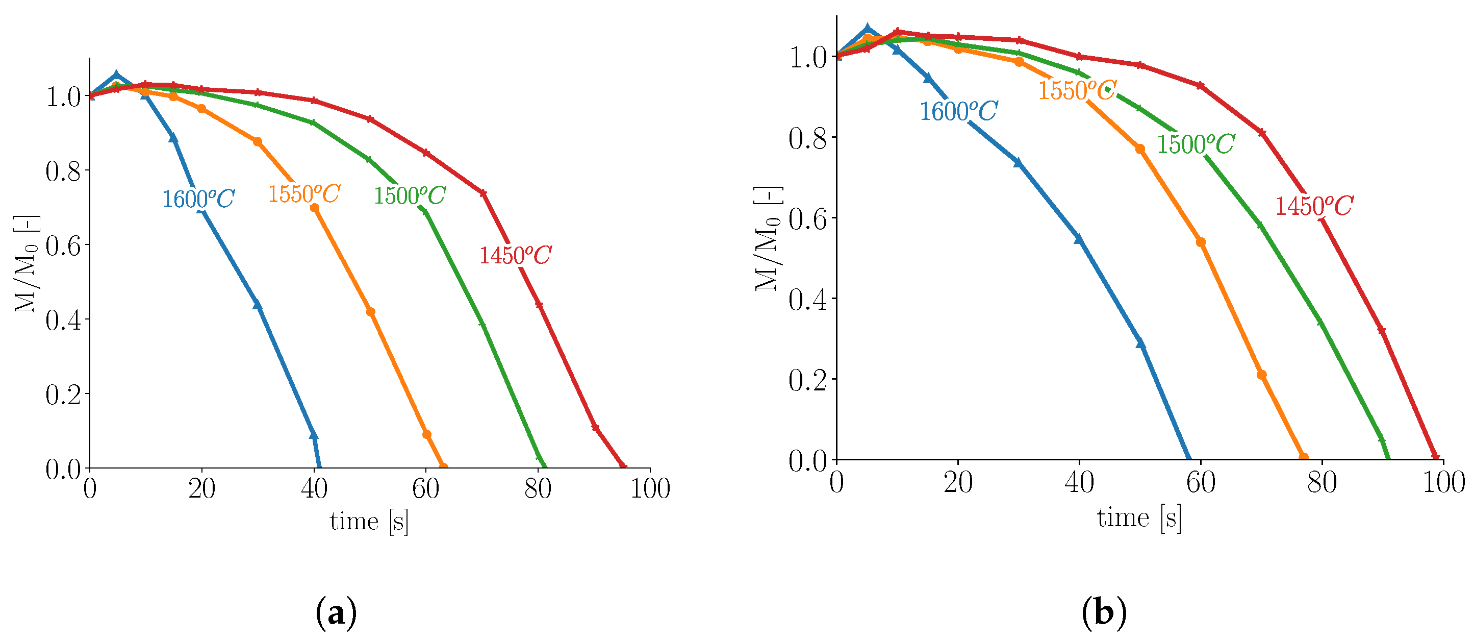
Recently, Xi et al. [48] studied the melting of cylindrical and square steel bars experimentally. Heat transfer coefficients (or Nusselt numbers) were not reported. However, the influence of initial temperatures of both melt and steel bars on melting was investigated. Results revealed that increased initial melt temperatures decreased steel bar melting times, confirming the linear decrease in melting time reported by Li et al. [27]. Individual square bars showed more pronounced shell formation compared to round bars due to their higher surface areas. Thus, square bars exhibited relatively longer melting times compared to round bars. Figure 2 shows mass-based normalized melting profiles of both round and square bars at an initial temperature of 25 °C submerged in baths of the same material at different temperatures.
Although heat and mass transfer are analogous phenomena, their strongly coupled nature in BOF processes has received limited attention. This strong coupling is attributed to the large heat generation during refining stages. For simplification, these phenomena are often studied individually, assuming small gradients in neglected key variables.
Steel dissolution has been studied experimentally under isothermal conditions [8,12,49,50]. Such studies enable quantification of mass transfer coefficients due to carbon diffusion from liquid melts to solid steel.
Szekely et al. [8] used constant heat transfer coefficients ranging between 3407 and 11,357 W / ( m 2 K ) to study dissolution rates of steel rods in hot metal baths. Carbon concentrations in baths and rods ranged from 3.8 to 4.4% and 0.22 to 0.27%, respectively. Temperatures were maintained below steel rod melting points. Rod melting was observed even when bath temperatures were below steel melting temperatures. In this case, melting was driven by carbon diffusion into steel rods. Additionally, shell formation was observed.
Wright [12] used iron rod dissolution results in Fe-C quiescent melts to fit Sherwood correlation (10) as a function of Grashof and Schmidt numbers, valid for G r S c > 10 9 :
S h = 0.13 ( G r S c ) 0.34
Rod dissolution rates were estimated from rod diameter variations and immersion times. Additionally, temperature and carbon content influences on dissolution rates were investigated. Temperature variation results shown in Figure 3a indicate increased dissolution rates as functions of melt temperature.
Penz et al. [52,53] studied steel rod dissolution in liquid hot metal experimentally and numerically, driven by concentration gradients. Steel rod dissolution rates were investigated in both static and rotating modes (i.e., during natural and forced convection, respectively). The modes were intended to simulate natural and forced convection caused by hot metal flow in BOF processes. The results revealed that dissolution rates using rotating rods were approximately twice those of static rods under identical conditions. The shell formation was observed for approximately 10 seconds, with shell size strongly dependent on the initial temperatures of rods and melts. The maximum shell thickness was estimated at 25% of the initial radius [51]. Mass transfer was estimated using liquidus carbon concentrations at equilibrium temperatures. Figure 3b shows distorted shapes of melted steel rods at different immersion times [51].
In their numerical work, Penz et al. [54] used Nusselt correlation (14) (Table 1) for vertical rods to estimate heat transfer coefficients. Heat transfer equations were solved in cylindrical coordinates considering only radial temperature variations. Their solution showed heat transfer coefficients higher than experimental results by a factor of 10. This difference was attributed to shell formation and trapped gases between shells and rods, which reduced external heat transfer values. Later, Deng et al. [55] indicated that axial temperature variations exist and are not constant as assumed by Penz et al. [54]. This variation between top and bottom introduces circulation flow. After approximately 20 s, thermal equilibrium is reached, at which point circulation flow is driven by concentration gradients.
Table 1. Average Nusselt correlations for natural convection for sphere, vertical plate, and vertical cylinder valid for low Prandtl numbers.
ShapeReferenceRangeCorrelation
Sphere[37] R a , P r N u 2 = 0.589 R a 1 / 4 [ 1 + ( 0.43 / P r ) 9 / 16 ] 4 / 9 (11)
Sphere[16] G r , 0.014 < P r < 0.219 N u 2 = 10 3.746 ( G r P r ) 0.878 (12)
V.P.[45] R a < 10 9 N u = 0.68 + 0.67 R a 1 / 4 [ 1 + ( 0.492 / P r ) 9 / 16 ] 4 / 9 (13)
V.C.[54,56] 0.1 < R a < 10 12 , P r 0.001 N u = 0.825 + 0.387 0.67 R a 1 / 4 [ 1 + ( 0.492 / P r ) 9 / 16 ] 4 / 9 2 + 0.87 L d (14)
∀: valid for all values; R a = G r × P r ; V.P.: vertical plate; V.C.: vertical cylinder.

2.2. Melting in Presence of Forced Convection

Forced convection heat transfer occurs when hot metal flow is driven by pressure differences induced by external sources. Such flows typically produce thinner momentum boundary layers compared to natural convection. Under these conditions, heat transport is dominated by convection. Relevant Nusselt number correlations for spheres, derived from experimental studies, are summarized in Table 2. These correlations converge to a Nusselt number of N u = 2 as the Reynolds number approaches zero ( R e 0 ), consistent with theoretical expectations. Notably, Equations (23)–(25) share similar characteristics: all are applicable for Prandtl number P r = 0.014 and are valid within Reynolds number ranges of 5162 to 7148. In contrast, Equation (26) covers broader Reynolds number ranges extending into the turbulent regime.
One of the earliest studies to estimate heat transfer coefficients in forced convective flows was conducted by Whitaker [57]. Whitaker developed the empirical correlation given in Equation (15) for flow past single spheres:
N u 2 = ( 0.4 R e 1 / 2 + 0.06 R e 2 / 3 ) P r 0.4 ( μ b / μ 0 ) 1 / 4
The correlation is valid for ranges of 35,000–76,000, 0.6–380, and 1–3.2 for R e , P r , and ( μ b / μ 0 ) , respectively. Whitaker assumed constant thermophysical properties except for viscosity. Therefore, the heat transfer coefficient becomes a function of fluid viscosity at different system temperatures. The viscosity ratio ( μ b / μ 0 ) is estimated at bulk fluid temperature and sphere surface temperature. Ranz and Marshall [58] developed correlation (16) for single drop evaporation, valid for Reynolds and Prandtl number ranges of 0–200 and 0.7–380, respectively:
N u 2 = 0.6 R e 1 / 2 P r 1 / 3
Both Equations (15) and (16) are not applicable to fluids with low Prandtl numbers, such as hot metals.
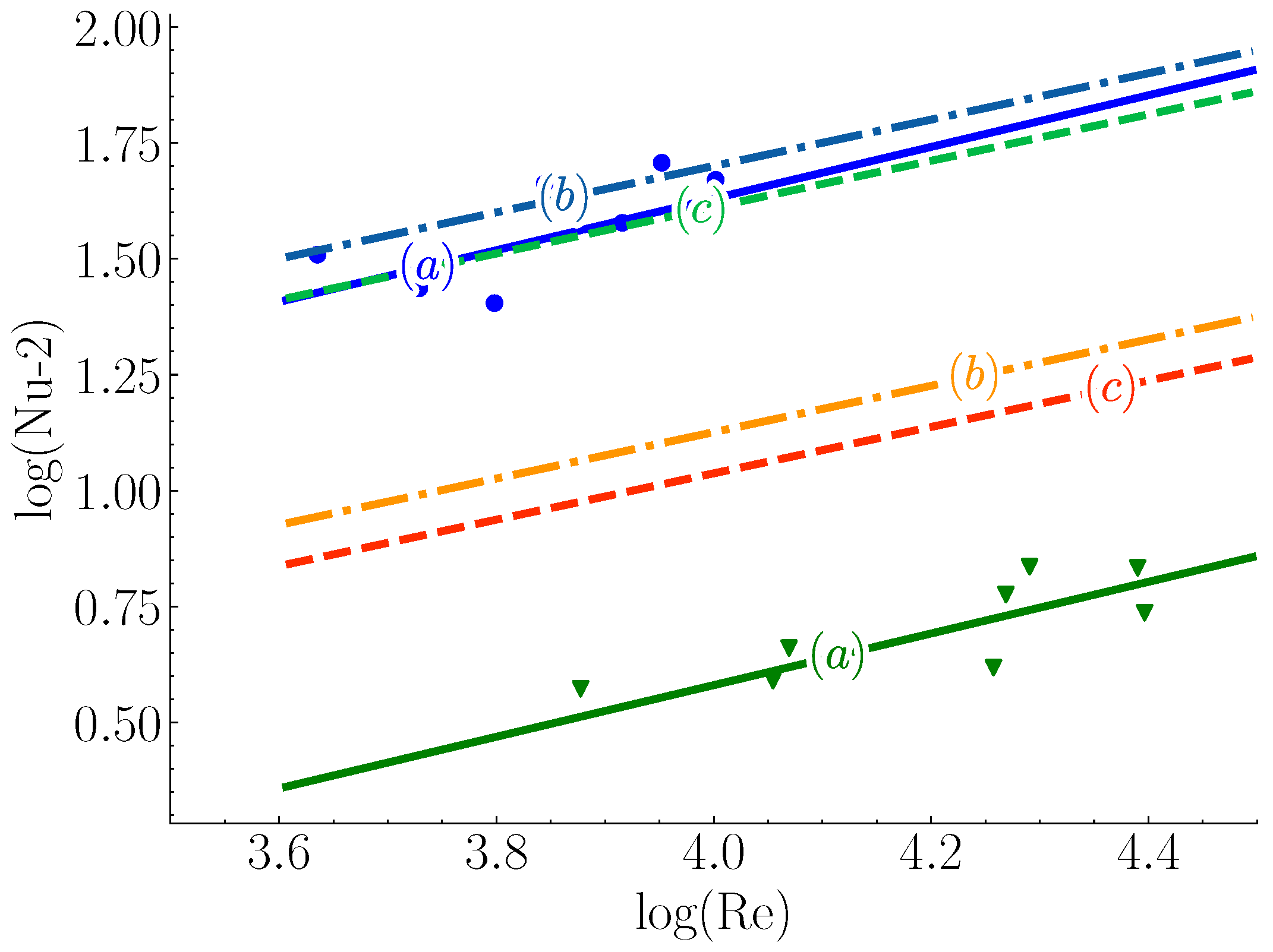
Argyropoulos et al. [16] investigated Nusselt correlation sensitivity to low Prandtl values by fitting semi-empirical correlation (23) to steel and aluminum experimental data for spheres in their melts. The Prandtl number exponent in the correlation was found to be higher than those in Hsu, Sideman [16], Whitaker, and Gunn correlations. Notably, correlation (23) produced better fits when compared to Hsu and Sideman correlations. Figure 4 shows experimental results for aluminum (triangles) and steel (circles) for Sideman and Hsu correlations (lines b and c, respectively) with the Argyropoulos et al. [16] correlation (line a). Additionally, Argyropoulos et al. [32] observed shell formation and estimated sphere mass increases between 40 % and 60 % . This shell thickness estimation is higher than results reported by Xi et al. [48] and Li et al. [27], but remains within the calculated range of Ehrich et al. [9]. Both Aziz et al. [59] and Hao et al. [30] did not report shell formation for ice-water systems with 10 °C temperature differences for ice particles at −10 °C.
Melissari and Argyropoulos [13] developed a dimensionless correlation (17) based on theoretical studies for immersed spheres over wide ranges (0.003–10) of low Prandtl numbers and applicable for Reynolds number ranges (100–50,000):
N u 2 = 0.47 R e 1 / 2 P r 0.36
The Prandtl number exponent in this correlation is still higher than Whitaker and Gunn correlations but lower than experimental correlation (23). Direct numerical simulation was conducted by Rodriguez et al. [60] to evaluate different theoretical and experimental correlations. Their simulation results revealed that correlation (23) underestimates heat transfer coefficients while correlation (17) overestimates them. Notably, the Witt correlation (26) performed better than correlation (23) relative to simulation results.
Bottom-blown gas in BOF enhances scrap melting. This has been investigated by many researchers [11,31,32,61] in the context of heat transfer from single spheres in plumes. Iguchi et al. [11] investigated flow turbulence intensity influences using both water jets and bubbling gas on single ice spheres. Their results indicated higher heat transfer for gas plumes, attributed to different turbulence effects induced by plume jets. This effect reduces boundary layer thickness, thereby enhancing heat transfer and increasing Nusselt numbers. Iguchi modified the Whitaker correlation to account for turbulence intensity ( τ ) by multiplying the left-hand side of Equation (15) by ( 1 + τ ) 1.36 . Argyropoulos et al. [32,61] also quantified flow turbulence effects using two spheres of different materials. Aluminum and steel spheres were immersed in their respective melts. Forced convection heat transfer was induced by rotating spheres and introducing argon gas plumes. Results showed that Nusselt numbers for plumes were higher than for rotating sphere setups, confirming the results of Iguchi et al. [11].
Shape variation effects during melting on heat transfer influence heat flux due to surface area variations. Hao et al. [30] studied this effect in ice-water systems using image analysis. Shape variation effects were quantified by measuring equivalent surface and volume particle diameters. Small variations between surface-based and volume-based diameters were observed at melting completion. Nonetheless, diameter profiles were identical for both surface-based and volume-based diameters. They developed correlation (18) to calculate Nusselt numbers. However, their empirical correlation is only applicable to narrow Prandtl number ranges ( 7.91 P r 12.69 ), limiting its applicability to steelmaking processes:
N u = 0.118 R e 0.431 G r 0.0898 P r 0.748 S t 0.167
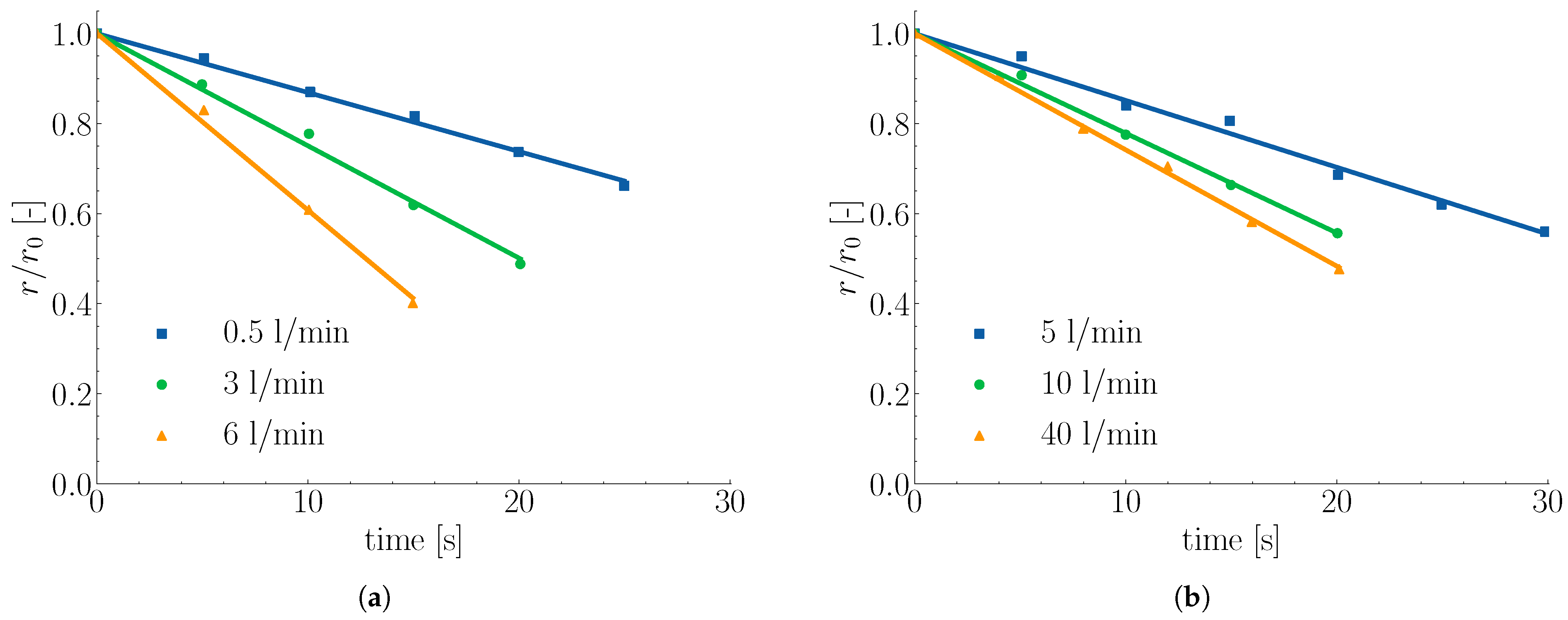
While the above studies focused on heat transfer coefficients by estimating Nusselt numbers, Wright [12] estimated mass transfer coefficients for steel rod melting in isothermal Fe-C melt systems. Melts were agitated using nitrogen gas injected at the bottom. Rods of the same radius (6 mm) and different lengths were used in two different amounts of Fe-C melt (with different furnace capacities). This was necessary to ensure that initial carbon concentrations were not affected by carbon dissolution into rods. Dissolution rates under turbulent forced convection influence were estimated by plotting rod diameter versus immersion time as functions of different gas flow rates. Results revealed linear relationships between diameter variations and time for different gas flows, indicating constant melting rates as shown in Figure 5. The obtained mass transfer coefficient under forced convection was found to depend on gas flow rate and more precisely on the plume velocity. Furthermore, the melting rate variations between different curves became smaller, indicating that gas flow rate increases above specific flow rates, resulting in poor heat transfer as stated by Wright.
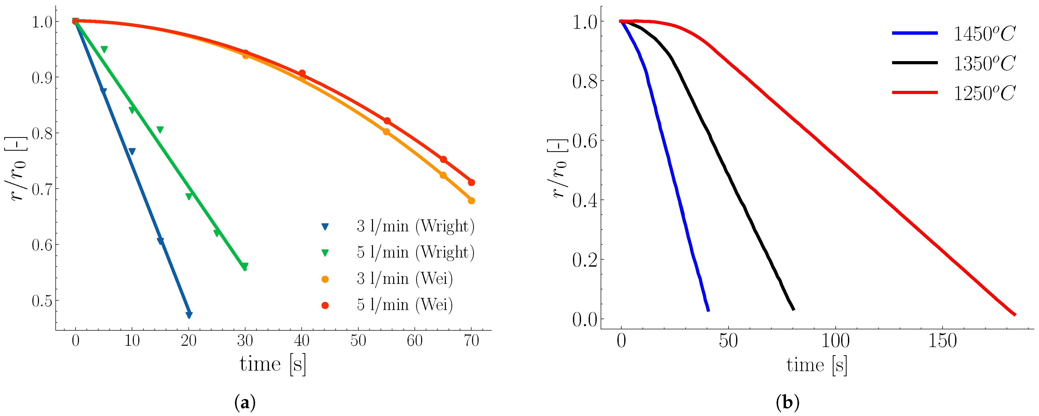
A similar study was reported by Wei et al. [62] to estimate the steel rod dissolution in a 150 kg induction furnace. The rods were immersed in pig iron melts with carbon content of 3 % . The melts were agitated using bottom-blown nitrogen gas at different flow rates of 3, 5, and 7 L/min. The results from Wei et al. [62] showed dissolution rate increases proportional to carbon concentration gradients and agitation intensity, in accordance with results reported by Wright [12]. However, from a quantitative perspective, melting profiles obtained by Wei et al. [62] show linear melting rates, while Wright’s [12] results show constant melting rates as shown in Figure 6a. Notably, initial carbon concentration gradients for Wei et al. [62] and Wright [12] experiments were 4.24 % and 2.65 % , respectively, while melt temperatures for both were 1400 °C. This melting rate variation could be related to different rod compositions.
Another study was performed by Isobe [49] to estimate steel rod dissolution rates in a 5-ton converter. Isobe modified the Lommel and Chalmers correlation [63] to account for small dissolution rates as given in Equation (19):
d r d t = h m * % C h m % C l i q % C l i q % C s c
where ( h m * ) is the moving mass transfer coefficient relative to the moving interface. The melting profile of Isobe’s model for single rods is shown in Figure 6b. Isobe obtained a non-dimensional correlation as given in Equation (20) for rotated rods:
S h = 0.0163 R e 0.78 S c 0.356
Furthermore, the melting profiles showed non-linear trends for the first 35 % of melting time, agreeing with results of Wei et al. [62], and linear profiles for the remaining melting time, similar to Wright [12].
For shapes other than spheres and cylinders, Kurobe et al. [10] studied melting processes of prismatic objects. Cold models (ice-water) were employed to investigate zinc ingot melting in hot-dip plating baths. Thermal similarity analysis was performed using two correlations applicable for liquid metals and water to estimate Nusselt values. Notably, equivalent surface diameters of prisms were chosen as characteristic lengths. They indicated the importance of including turbulence intensity in scaling correlations as presented by Equation (21):
N u = 1.128 P r 0.5 R e 0.5 ( 1 + u / u ^ ) 1.36
Also, Shukla et al. [31] performed cold model experiments on different shapes: spheres, cylinders, and plates. Bottom argon gas was used to induce forced convection heat transfer. They found that melting rates ( d r / d t ) were not influenced by object shapes, in contrast to melting times. Shukla et al. [31] fitted Nusselt correlations of the form N u = c R e n P r 1 / 3 to estimate c and n coefficients for each shape individually and all shapes together. The estimated errors in coefficients for all shapes together (shown in correlation (22)) were greater than those obtained for individual shapes:
N u = 0.0281 R e 0.8591 P r 1 / 3
This variation could be attributed to correlation sensitivity to characteristic length scale choices. Cao et al. [64] used ice cured with quartz particles in an 80-ton water converter. Different sizes of cured ice (plate shapes) were used to model scrap melting in BOF. The results indicated better mixing and heat distribution for small scrap pieces. Therefore, the study suggested avoiding large scrap pieces during BOF operation.
Table 2. Nusselt correlations for forced convection regime based on experimental measurements.
ShapeReferenceRangeCorrelation
Sphere[16] 4330 R e 20 , 780 ,   0.014 P r 0.219 N u 2 = 1.114 R e 0.557 P r 0.914 (23)
Sphere[61] 2797 < R e < 7148 , P r 0.014 N u 2 = 10 4.817 R e 1.556 (24)
Sphere[32] 5162 < R e < 21 , 273 ,   P r 0.014 N u 2 = 10 2.811 R e 0.585 P r 2.386 (25)
Sphere[65] 35 , 000 < R e < 152 , 500 ,   P r = 0.001 N u 2 = 0.386 R e 0.5 P r 0.5 (26)

2.3. Influence of Scrap Solid Fraction on Heat Transfer in Liquid Hot Metal

An analogy exists between heat transfer and drag forces in bulk particulate systems [18,25,28]. Just as drag forces contribute to particle clustering in fluidized beds (alongside other factors such as particle–particle collisions), heat transfer processes lead to the formation of hot and cold zones within systems. Such non-uniform temperature distributions deteriorate process operation and can potentially lead to unmelted scrap, as observed in BOF operations. Consequently, accurate heat transfer prediction in high solid fraction systems (characterized by low voidage in scrap piles) is crucial for ensuring operational stability. Hot and cold zones were observed by Gaye et al. [66] in industrial BOF experiments, who reported that melting times of small scrap pieces were in some cases longer than those of large ones under typical converter conditions, indicating non-uniform temperature distribution among different scrap pieces.
Porosity influence on heat transfer plays a crucial role in controlling melting rates. Low porosity can severely restrict fluid motion and convective heat transfer, leading to incomplete melting, longer melting times, and cold zone formation. Therefore, understanding and quantifying porosity impacts on melting behavior is essential for reliable process efficiency prediction.
Whitaker [57] developed the correlation in Equation (27), applicable to staggered cylinders and granular systems (e.g., packed beds). However, the correlation is only valid for porosities (voidage) below 0.65 , Prandtl number 0.7 , and Reynolds numbers above 50:
N u = 0.5 R e 1 / 2 P r 1 / 3 + 0.2 R e 2 / 3 P r 1 / 3
By introducing porosity explicitly (voidage fraction ε ) as an independent variable in Nusselt correlations, Gunn [25] introduced one of the most widely used expressions for dense systems, shown in Equation (28):
N u = a ( 1 + b R e p 1 P r p 2 ) + c R e p 3 P r p 4
where a = ( 7 10 ε + ε 2 ) , b = 1 , c = ( 1.33 2.43 ε + 1.2 ε 2 ) , p 1 = 0.2 , p 2 = p 4 = 1 / 3 , and p 3 = 0.7 . Unlike Whitaker’s [57] correlation, Gunn’s formulation is applicable over wider porosity ranges ( 0.35 1 ) and for Reynolds and Prandtl numbers in ranges of ( 1 10 5 ) and ( 0.6 380 ), respectively. However, its sensitivity to low Prandtl numbers (e.g., in liquid steel where P r < 0.6 ) has not been quantified.
Jiang et al. [29] examined how porosity influences melting in packed beds of spherical ice under both normal gravity and microgravity. They observed that, for identical flow conditions, bed average Nusselt numbers were lower than those of single, isolated spheres.
For stagnant melts, Li et al. [6] investigated the melting behavior of two and multiple rods. They classified porosity influence on melting behavior into three categories: (i) independent melting, (ii) partially agglomerate melting, and (iii) fully agglomerate melting. This classification has important implications for process operation, as melting time is no longer determined by individual object melting but by agglomerated multiple object states. Therefore, this indicates non-linear increases in melting time with increasing solid fraction. Similarly, Xi et al. [7] reported that high porosity (near 1) leads to independent rod melting, low porosity (below 0.66 ) results in partially independent melting, and very low porosity causes fully dependent (agglomerated) melting. Hence, this confirms results of Li et al. [6]. It is important to note that the above studies [6,7] were conducted under natural convection conditions, in the absence of external agitation. Such conditions are relevant to BOF operation during two key intervals: (i) between hot metal charging and before refining step initiation; (ii) after refining and prior to tapping. In contrast, studies by Gaye [66], Jiang [29], and Tavassoli [24] involved enhanced heat transfer through fluid flow.
Given porosity influence on melting time (t), Xi et al. [7] developed the correlation in Equation (29) to estimate the melting time (t) of multiple objects based on the melting times of their single constituents ( t i ). The correlation requires prior knowledge of how porosity, preheating, liquid temperature, and stirring affect scrap melting time to estimate the K p o r o s , K p r e h T , K l i q T , and K s t i r r i n g factors, respectively. These factors represent melting time ratios between investigated systems and single scrap under these four variations:
t = t i K p o r o s × K l i q T K p r e h T × K s t i r r i n g
For these factor definitions, the reader is referred to [7]. Although relation (29) was developed for EAF, a similar approach may be applied to BOF processes.
Finally, in BOF operation, melting time increases due to agglomeration can severely affect operational efficiency and energy consumption, as agglomerate melting could delay subsequent process stages or reduce productivity (e.g., due to unmelted scrap). Therefore, both melting rate and melting time are important. The former is strongly influenced by material composition, melt state (e.g., temperature; carbon concentration), flow characteristics (e.g., laminar, turbulent, and stirring type), and heat and mass transfer (natural or forced). Conversely, melting time depends on both melting rate and object geometry.
Experiments involving single objects (e.g., spheres or rods) in quiescent melts are widely used to study heat and mass transfer. These are particularly useful in estimating maximum shell thickness, which strongly depends on heat transfer coefficient (Nu) and carbon concentration differences between melt and scrap. Here, it is important to emphasize the relationship between Stefan number and carbon concentration. This relationship can be obtained from Fe-C phase diagrams as in reference [49].
However, from an operational perspective, shell formation and its melting behavior are strongly influenced by pile porosity (solid fraction), which is crucial in estimating scrap pile melting time. Also, correct characteristic length selection is crucial to correctly estimate Nusselt (Sherwood) numbers for heat (mass) transfer.
Therefore, to correctly simulate scrap melting, mathematical expressions for Nusselt (Sherwood) numbers and porosity are essential. Gunn’s correlation has been used extensively to model heat (mass) transfer (especially in fluidized and packed bed fields). However, Gunn’s correlation accuracy for non-spherical particles and low Prandtl numbers still needs further investigation [67,68]. Furthermore, shell formation and its melting dynamics impose extra constraints on simulation approaches. This is because there are varieties of possible scenarios such as individual scrap cases, agglomeration of few scrap pieces, agglomeration of whole piles, or exterior layer formation.

3. Modeling Scrap Melting

BOF steelmaking will continue to dominate the high-quality crude steel production in upcoming decades. Increased scrap usage in BOF under the present industry settings demands further detailed investigation on scrap melting efficiency and mechanisms. Hence, understanding mechanical (particle–particle and particle–fluid interactions), chemical (carbon dissolution; decarburization reactions), and thermal (heat transfer and phase change) phenomena is essential to maximize scrap usage without compromising metallurgical performance.
Numerical simulations are valuable tools to investigate process parameter variations without hindering real process stability. From a modeling perspective, scrap melting problems fall under moving interface problems (also known as Stefan’s problems) and can be solved analytically or numerically for simple geometries assuming constant thermophysical properties [69].
One of the early analytical studies was conducted by Goldfarb et al. [70]. They derived a simple analytical model to predict scrap phase change during melting for different shapes (plates, cylinders, and spheres). The model showed distinct regions along melting profiles, including (i) shell formation around cold immersed scrap, (ii) shell melting, (iii) diffusive melting of solid, and (iv) melting of remaining heated solid. Szekely et al. [8] and Ehrich et al. [9,39] both used Green’s function to analytically model scrap melting. Szekely solved heat and mass transfer for rods and used temperature–concentration correlations of Fe-C phase diagrams to estimate interface temperatures. They assumed constant heat and mass transfer coefficients. Ehrich et al. [9,39] solved heat transfer for spheres in spherical coordinates. They divided spherical domains into core (dense iron) and shell (frozen melt) zones. They considered constant external heat transfer coefficients. They showed that frozen shell thickness depends on core initial temperature and melt properties. Analytical solutions using Green’s function usually produce integral terms that need numerical evaluation.
The analytical methods are limited when applied to complex geometries or systems with porosity variation and dynamic flow behavior. Therefore, numerical simulation tools have proven to be essential and safe alternatives to investigate such high-temperature systems [71,72,73,74]. However, challenges regarding local transport phenomena resolution remain computationally demanding due to the multi-scale, multi-physics nature of systems. In general, finite difference (FD), finite volume (FV), and finite element (FE) methods can be used to simulate scrap melting processes. All aforementioned numerical methods share the concept of discretizing objects into small cells (or control volumes). Even though these numerical methods can be utilized to simulate scrap melting phenomena, the conservative nature of FV has made it a popular numerical approach in modeling steelmaking BOF.
The following sections focus on computational fluid dynamics (CFD) and the discrete element method coupled with CFD (CFD-DEM), and the particle-resolved direct numerical simulation with immersed boundary method (PR-DNS/IBM) for simulating heat transfer with emphasis on scrap melting.

3.1. CFD Simulation of Scrap Melting

CFD is widely used to model oxygen jet impingement [71,72,75], casting processes [76], and scrap melting [10,26,55,64,77]. In the context of scrap-hot metal, conjugate heat transfer models use different equation sets for two regions (solid and fluid). In solid regions, only energy is solved. While in fluid regions, mass, momentum, and energy equations are solved in discretized domains. The governing equation for a conserved scalar quantity ( ϕ ) is concisely given in Equation (30):
ρ ϕ t + · ( ρ ϕ u ) = · q + S ϕ
where ρ is the density [ kg / m 3 ], u is the velocity vector [ m / s ], q represents the diffusive flux, and S ϕ is the source term. Equation (30) describes mass conservation when ϕ = 1 , momentum when ϕ = u , energy when ϕ = h , and species when ϕ = Y i . In energy equations, source term S ϕ accounts for melting effects. Different approaches incorporate latent heat [78,79] in melting processes. However, the source term method, heat integration, and enthalpy methods are widely used in modeling melting processes. In the latter approach, enthalpy is expressed as a piecewise linear function of temperature, while in the source method, total enthalpy (sensible and latent) is substituted directly in energy conservation equations. It is worth mentioning that the enthalpy method is an implicit method for identifying whether cells are filled with liquid, solid, or partially filled (interface cells).
Melissari et al. [15] used the heat integration method to model single-sphere melting of magnesium alloys using finite volume approaches, where computational domains were divided into solid and liquid regions. In their model, mass, momentum, and energy equations were solved. They used liquid fraction (equivalently solid) methods to model phase change. Liquid fraction f l estimation due to heat transport is calculated from Equation (31):
f l = T s o l T T s o l T l 1 1 κ
where κ , T s o l , and T l represent specific material constants (obtained from phase diagrams), solvent temperatures, and alloy liquidus temperatures, respectively. Kruskopf et al. [80,81] solved heat and mass transport equations to capture system melting and diffusion phenomena. They used moving interface nodes to represent shell solidification and melting. Melting rates were determined by interface speeds, driven by enthalpy differences between adjacent cells (relative to interface cells). The developed model agreed with experimental data from Isobe [49] but overestimated shell formation.
Cao et al. [64] used enthalpy methods to model melting processes. Different ice shape melting was compared with scaled-down converter experimental data. The model used correlation (32) to estimate liquid melt fractions as functions of ice solidus and liquidus temperatures:
f l = T T s T l T s
Furthermore, Deng et al. [26] used the same method to estimate melting times of different scrap types (light, medium, and heavy based on densities) to utilize more scrap during melt waiting times before further processing. Deng et al. [26] solved heat transfer problems for rods in radial directions and compared results with rod temperature profiles. Later, Deng et al. [55] included species transport equations for single rod melting. They used linear correlations to account for liquid fractions, similar to Equation (32). The model was able to predict non-uniform melting along bar vertical axes as well as shell formation. Xi et al. [7] considered extra terms in momentum equations to account for natural convection caused by temperature variations between melt tops and bottoms. The results were used to predict scrap melting times as represented by correlation (29). In contrast to Deng et al. [55] and Xi et al. [7], Penz [54] only solved heat transfer, neglecting carbon exchange between phases. The obtained heat transfer coefficient from their results was an order of magnitude higher than experimental data.
The above simulations focused on a single object melting (also known as representative element volume (REV) [19]). Also, larger systems have been simulated using CFD [71,72,73,82]. Lv et al. [72] showed CFD potential in developing and optimizing EAF and BOF. Arzpeyma et al. [82] simulated scrap melting in EAF baths using enthalpy–porosity methods. They simulated different scrap shape melting (cylindrical and cubes) under forced and natural convection influences. Hot metal flow in forced convection cases was driven by electromagnetic stirring. The model was able to capture shell formation through liquid fraction variations in neighboring cells where shell sizes are influenced by mixing techniques.
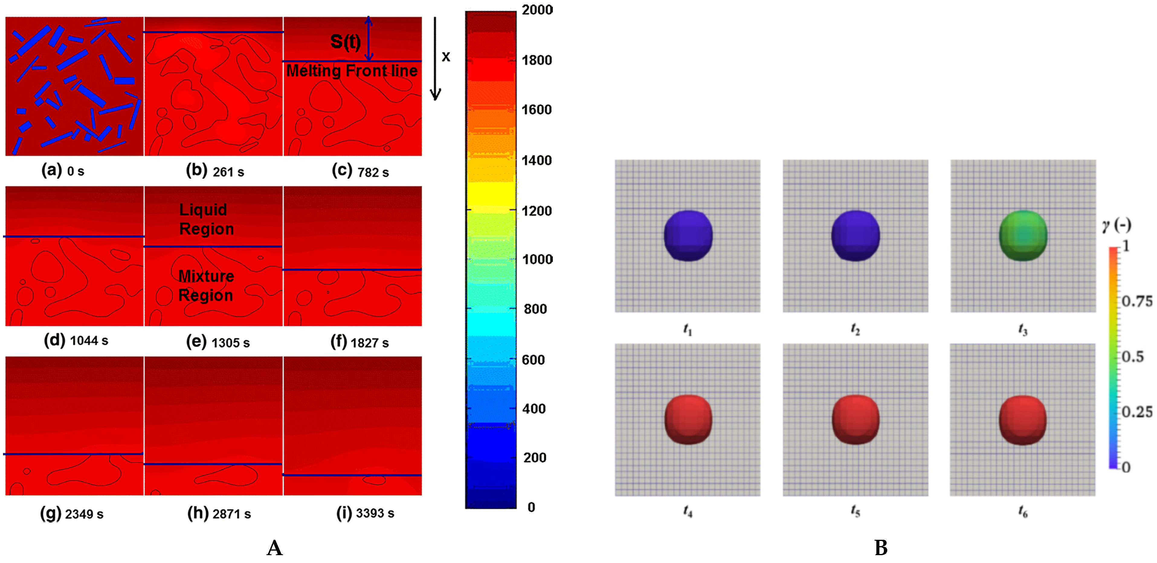
Another method such as the phase-field technique [83] has been used to model scrap melting [6,27]. Phase-field methods use indicators ( ϕ ) to track interfaces. Indicators ( ϕ ) take constant values (e.g., 1 in solid phases and −1 in liquid phases), but these values vary between two limits in interface regions. Phase-field methods have the ability to model coalescence of different melting objects as shown in Figure 7A. This approach requires resetting indicators ( ϕ ) when meshes are refined, hence it is computationally expensive. Another limitation is interphase thickness specification. Another popular interface modeling approach is the volume of fluid (VOF) method. Even though it has few limitations (e.g., numerical diffusion) and introduces extra equations to conservation equation sets (mass, momentum, energy, and species), it conserves mass and requires less computational effort. It is widely used in multiphase flow modeling (e.g., classical dam break, buoyant bubble rise, and primary atomization). It has also been coupled successfully with DEM to model discrete phase melting. Wang et al. [84] used VOF methods to model iron pellet melting containing different carbon concentrations as shown in Figure 7B. Although it gave good results, it required small mesh sizes (order of 10 times smaller than pellet diameters).

3.2. CFD-DEM Simulation

The limitation of solid dynamics modeling in CFD is one of the driving forces to couple the discrete element method (DEM) with CFD. In DEM, Newton’s laws for translational and rotational motion are solved for each particle to obtain its position, velocities, and contact forces [85,86,87]. CFD-DEM has been used extensively [88,89,90] in different engineering applications, such as the pneumatic transportation of granular materials [28], scrap melting in EAF [91], and mining and geotechnical engineering [86,88,92].
Vångö et al. [93] used CFD-DEM with volume of fluid (VOF) to model multiphase flow hydrodynamics of BF hearths. Results showed velocity distributions near hearth outlets and mass flowrates drained from hearths due to floating bed sinks pushing hot metal out of deadman zones. Later, Nijssen et al. [94] conducted similar work to Vångö. They analyzed BF hearth flow characteristics and deadman dynamics influences on liquid flow. Additionally, they modeled temperature and carbon distributions using Gunn’s correlation to estimate heat and mass transfer between solid and liquid phases. Also, Wang et al. [84] used VOF with DEM to simulate iron pellet melting on stationary coke particle beds. The model was able to capture holdup (voidage fraction filled with melt) and pellet melting profiles. Recently, Lichtenegger et al. [74] developed a new CFD-DEM approach that allows modeling over large process time scales. The method uses steady-state assumptions when granular bed dynamics remain unchanged, allowing for faster simulations. Bansal et al. [95] successfully modeled spherical ice particle melting using CFD-DEM. They used Ranz–Marshall correlation (14) as closure in their numerical model, leading to correct melting profiles for single spheres when compared with the experimental data of Hao and Tao [30]. They showed that using bulk temperature in cases of forced or mixed convection is more accurate than using film (also known as reference) temperature to estimate melting rates.
It is important to note that less attention has been given to particle growth (i.e., shell formation) in CFD-DEM modeling in steelmaking industries. DEM has the ability to model swelling/growth of spherical particles [96], but non-spherical particles, more specifically triangulated particles, are still far from such developments. Braile et al. [97] indicated that swelling models require experimental evaluation of kinetic parameters ( κ ) of correlation (33) to obtain volume differences (V) as functions of time due to swelling:
V = 1 e κ t
Generally, in DEM and specifically in swelling models, it is important to choose time-steps carefully to avoid excessive particle overlap and allow for energy dissipation to occur. Even though CFD-DEM has proven to be significantly useful for large-scale systems, it still has limitations in resolving local transport phenomena (e.g., thermal boundary layers), also known as unresolved methods. Therefore, empirical correlations are still required to describe such phenomena.

3.3. Particle Resolved Direct Numerical Simulation with Immersed Boundary Method (PR-DNS/IBM)

This method falls under the class of direct numerical methods. It resolves flow around immersed objects (particles) using the immersed boundary method (IBM). Furthermore, it can be used to obtain accurate closure correlations (e.g., heat transfer coefficients) which can be used in CFD-DEM simulations of large-scale systems. Unlike CFD-DEM, cell sizes in this method must be relatively small (i.e., factor of 20–30 smaller than the grid size) compared to particle sizes. Table 3 gives an overview of different levels of CFD accuracy and differences between each method. Typically in IBM methods, an extra source term is introduced in the momentum equation of the fluid to account for the immersed boundary [22,98]. To accurately compute heat and mass transfer rates at individual particle levels, thermal and mass transfer boundary layers need to be resolved [21,24]. Deen et al. [17,18,22] used IBM-DEM methods to simulate flow and heat transfer in dense fluidized systems. Their approach captured solid–fluid interfaces without requiring equivalent particle diameters. They investigated flow characteristics and heat transfer in both stationary particle arrays and fluidized bed systems.
Gunn’s correlation [25] is considered one of the most accurate empirical relations to predict local transport phenomena. Tavassoli et al. [99] performed DNS on sphero-cylindrical particles and investigated the influence of effective diameters used in Gunn’s correlation. Figure 8a shows the dimensionless temperature distribution of fluid in randomly packed sphero-cylindrical systems. Three types of diameters were tested: equivalent volume of sphere, Sauter diameter (defined as 6 V / A ), and diameter of the cylindrical part. Different aspect ratios ( L / D ) were analyzed and compared to the modified Gunn’s correlation with the following parameters: a = ( 7 10 ε + 5 ε 2 ) , b = 0.1 , and c = ( 1.33 2.19 ε + 1.15 ε 2 ) as shown in Figure 8b. Zhu et al. [68] collected different DNS results and performed curve fitting on Gunn’s correlation to obtain polynomial constants of Equation (28). The fitted correlation has the following fitted parameters: a = ( 0.83 16.21 ε + 14.67 ε 2 ) , b = 0.01 , and c = ( 1.5 2.6 ε + 1.13 ε 2 ) . The power exponents p 1 , p 2 , p 3 , and p 4 remain the same as the original Gunn’s correlation.

4. Conclusions and Outlook

This study has examined different phenomena related to the scrap-hot metal with focus on BOF conditions. Special attention was given to heat transfer correlations in both natural (Section 2.1) and forced (Section 2.2) convective flows, shell formation, and melting behavior of single objects. Additionally, porosity influence on scrap pile melting behavior and heat transfer (Section 2.3) was reported by measuring melting times and estimating heat transfer coefficients of bulk systems, respectively.
The review revealed that natural convection contributes to maximum shell thickness formation in quiescent melt conditions for individual objects. This formation is influenced by temperature differences between solid and liquid phases, heat (mass) transfer coefficients, flow characteristics, and object geometry. However, such maximum sizes are unlikely to occur in BOF conditions due to the highly turbulent nature of hot metal flow and the presence of scrap pile porosity. The former (turbulence) tends to reduce shell thickness by enhancing convective heat transfer at scrap–melt interfaces, particularly in temperature ranges between 1250 and 1650 °C, which correspond to typical BOF melt temperatures. The latter (porosity) modifies shell formation and alters overall pile melting behavior.
Given the complex nature of scrap melting and dynamics in BOF, various modeling approaches have been developed to simulate individual scrap piece melting. However, combined effects of initial scrap arrangement and converter rocking have not yet been comprehensively investigated. CFD-DEM (i.e., multi-scale modeling) provides a powerful modeling framework to study multiple levels of BOF processes: DEM for capturing scrap distribution, PR-DNS/IBM for closure relations, and full-scale CFD-DEM for simulating BOF operation.
To the authors’ knowledge, no existing model evaluates the combined influence of initial scrap packing, rocking motion, and porosity distribution on scrap melting in BOF. DEM can be employed to analyze scrap characteristics and packing behavior (Level DEM). In parallel, particle-resolved DNS with immersed boundary methods (PR-DNS/IBM) offers a means to derive closure correlations (e.g., Nusselt number correlations) for non-spherical particles (e.g., vertical cylinders; plates). These correlations can then be integrated into CFD-DEM simulations to explore BOF process parameters without interfering with real operations.
The widely used Gunn correlation (Equation (28)), along with its various extensions, has proven effective in modeling heat and mass transfer for spherical, sphero-cylindrical, dense, and dilute particulate systems. Nevertheless, its applicability at low Prandtl numbers remains uncertain and likely requires refitting to ensure accuracy under such conditions. One notable limitation of modeling approaches such as PR-DNS/IBM and CFD-DEM in simulating particle melting is the assumption of isotropic shrinkage or growth of particle geometry, despite anisotropic heat and mass fluxes. This represents a significant modeling simplification, which has yet to be addressed in the literature. Furthermore, incorporating core–shell models in CFD-DEM simulations is critical to accurately capture scrap behavior during initial immersion phases. Particle swelling models could be adapted to simulate initial shell formation, followed by inner core melting. However, certain assumptions regarding shells and cores must be made to maintain computational feasibility for large-scale simulations.

Author Contributions

Conceptualization, M.B.A.H., F.C., B.R., F.N.H.S., J.A.M.K. and Y.Y.; methodology, M.B.A.H., F.C., B.R., F.N.H.S., J.A.M.K. and Y.Y.; formal analysis, F.C.; investigation, M.B.A.H., F.C., B.R., F.N.H.S., J.A.M.K. and Y.Y.; methodology, M.B.A.H., F.C., B.R., F.N.H.S., J.A.M.K. and Y.Y.; resources, M.B.A.H., F.C., B.R., F.N.H.S., J.A.M.K. and Y.Y.; methodology, M.B.A.H., F.C., B.R., F.N.H.S., J.A.M.K. and Y.Y.; writing—original draft preparation, M.B.A.H.; writing—review and editing, M.B.A.H., F.C., B.R., F.N.H.S., J.A.M.K. and Y.Y.; visualization, M.B.A.H., F.C., B.R., F.N.H.S., J.A.M.K. and Y.Y.; supervision, F.C., B.R., F.N.H.S., J.A.M.K. and Y.Y.; project administration, F.C., B.R., F.N.H.S., J.A.M.K. and Y.Y.; funding acquisition, F.C., B.R., F.N.H.S., J.A.M.K. and Y.Y. All authors have read and agreed to the published version of this manuscript.

Funding

This research was carried out under project number T20010 in the framework of the Research Program of the Materials innovation institute (M2i) www.m2i.nl (accessed on 1 June 2025) supported by the Dutch government.

Data Availability Statement

The original contributions presented in this study are included in the article. Further inquiries can be directed to the corresponding author.

Conflicts of Interest

Authors Florian Charruault, Bapin Rout, Frank N. H. Schrama were employed by the company Tata Steel Netherlands. The remaining authors declare that the research was conducted in the absence of any commercial or financial relationships that could be construed as a potential conflict of interest.

Abbreviations

The following abbreviations are used in this manuscript:
BOFBasic oxygen furnace
CFDComputational fluid dynamics
DEMDiscrete element method
PRParticle resolved
DNSDirect numerical simulation
BFBlast furnace
TFMTwo-fluid method
PIVParticle image velocimetry
IBMImmersed boundary method
REVRepresentative element volume

Appendix A

Table A1. Summary of the dimensionless numbers, their definitions, formulas, and physical meanings, illustrating their roles in fluid flow, heat transfer, and phase change phenomena.
NumberDefinitionFormulaPhysical Meaning
Reynolds ( R e )Ratio of inertial to viscous forces ρ U L / μ Describes the flow regime (laminar or turbulent).
Prandtl (Pr)Ratio of momentum to thermal diffusivity c p μ / k Indicates the relative thickness of velocity to thermal boundary layer.
Nusselt (Nu)Ratio of convective to conductive heat transfer h L / k Measures the enhancement of heat transfer by convection over conduction.
Schmidt (Sc)Ratio of momentum to mass diffusivity ν / D Indicates the relative thickness of the velocity boundary layer to the mass boundary layer.
Sherwood (Sh)Ratio of convective to diffusive mass transfer h L / D Describes the effectiveness of convective mass transfer compared to diffusion.
Stefan (Ste)Ratio of sensible to latent heat c p ( T m T 0 ) / l h Quantifies the available heat to continue the phase change.
Fourier (Fo)Ratio of time to diffusion scale time α t / L 2 Quantify availability of time for the diffusion to reach steady state.
Biot (Bi)Ratio of internal to external heat transfer resistance h L / k s Quantify the special distribution of the temperature inside the object.

References

  1. World Steel in Figures 2024—Worldsteel.Org. Available online: https://worldsteel.org/data/world-steel-in-figures-2024/#world-crude-steel-production-%3Cbr%3E1950-to-2023 (accessed on 11 July 2024).
  2. Bird, R.B.; Stewart, W.E.; Lightfoot, E.N. Transport Phenomena; John Wiley & Sons: New York, NY, USA, 2002. [Google Scholar]
  3. Holman, J.P. Heat Transfer; McGraw-Hill: New York, NY, USA, 2010. [Google Scholar]
  4. Schlichting, H.; Gersten, K. Boundary-Layer Theory; Springer: Berlin/Heidelberg, Germany, 2016. [Google Scholar]
  5. Stein, R.P. Liquid Metal Heat Transfer. Adv. Heat Transf. 1966, 3, 101–174. [Google Scholar] [CrossRef]
  6. Li, J.; Provatas, N. Kinetics of Scrap Melting in Liquid Steel: Multipiece Scrap Melting. Metall. Mater. Trans. B 2008, 39, 268–279. [Google Scholar] [CrossRef]
  7. Xi, X.; Chen, S.; Yang, S.; Ye, M.; Li, J. Melting Characteristics of Multipiece Steel Scrap in Liquid Steel. ISIJ Int. 2021, 61, 190–199. [Google Scholar] [CrossRef]
  8. Szekely, J.; Chuang, Y.K.; Hlinka, J.W. The Melting and Dissolution of Low-Carbon Steels in Iron-Carbon Melts. Metall. Trans. 1972, 3, 2825–2833. [Google Scholar] [CrossRef]
  9. Ehrich, O.; Yun-Ken, C.; Schwerdtfeger, K. The Melting of Metal Spheres Involving the Initially Frozen Shells with Different Material Properties. Int. J. Heat Mass. Tran. 1978, 21, 341–349. [Google Scholar] [CrossRef]
  10. Kurobe, J.; Iguchi, M. Cold Model Experiment on Melting Phenomena of Zn Ingot in Hot Dip Plating Bath. Mater. Trans. 2003, 44, 877–884. [Google Scholar] [CrossRef]
  11. Iguchi, M.; Morita, Z.I.; Tani, J.I.; Uemura, T. Flow Phenomena and Heat Transfer around a Sphere Submerged in Water Jet and Bubbling Jet. ISIJ Int. 1989, 29, 658–665. [Google Scholar] [CrossRef]
  12. Wright, J.K. Steel Dissolution in Quiescent and Gas Stirred Fe/C Melts. Metall. Trans. B 1989, 20B, 363–374. [Google Scholar] [CrossRef]
  13. Melissari, B.; Argyropoulos, S.A. Development of a Heat Transfer Dimensionless Correlation for Spheres Immersed in a Wide Range of Prandtl Number Fluids. Int. J. Heat Mass. Tran. 2005, 48, 4333–4341. [Google Scholar] [CrossRef]
  14. Melissari, B.; Argyropoulos, S.A. Measurement of Magnitude and Direction of Velocity in High-Temperature Liquid Metals. Part II: Experimental Measurements. Metall. Mater. Trans. B 2005, 36B, 639–649. [Google Scholar] [CrossRef]
  15. Melissari, B.; Argyropoulos, S.A. Measurement of Magnitude and Direction of Velocity in High-Temperature Liquid Metals. Part I: Mathematical Modeling. Metall. Mater. Trans. B Process Metall. Mater. Process. Sci. 2005, 36, 691–700. [Google Scholar] [CrossRef]
  16. Argyropoulos, S.A.; Mikrovas, A.C. An Experimental Investigation on Natural and Forced Convection in Liquid Metals. Int. J. Heat Mass. Tran. 1996, 39, 547–561. [Google Scholar] [CrossRef]
  17. Deen, N.G.; Van Sint Annaland, M.; Van der Hoef, M.A.; Kuipers, J.A. Review of Discrete Particle Modeling of Fluidized Beds. Chem. Eng. Sci. 2007, 62, 28–44. [Google Scholar] [CrossRef]
  18. Deen, N.G.; Peters, E.A.; Padding, J.T.; Kuipers, J.A. Review of Direct Numerical Simulation of Fluid–Particle Mass, Momentum and Heat Transfer in Dense Gas–Solid Flows. Chem. Eng. Sci. 2014, 116, 710–724. [Google Scholar] [CrossRef]
  19. Noël, E.; Teixeira, D. New Framework for Upscaling Gas-Solid Heat Transfer in Dense Packing. Int. J. Heat Mass Transf. 2022, 189, 122745. [Google Scholar] [CrossRef]
  20. Kim, J.; Choi, H. An Immersed-Boundary Finite-Volume Method for Simulation of Heat Transfer in Complex Geometries. KSME Int. J. 2004, 18, 1026–1035. [Google Scholar] [CrossRef]
  21. Tenneti, S.; Sun, B.; Garg, R.; Subramaniam, S. Role of Fluid Heating in Dense Gas–Solid Flow as Revealed by Particle-Resolved Direct Numerical Simulation. Int. J. Heat Mass Transf. 2013, 58, 471–479. [Google Scholar] [CrossRef]
  22. Deen, N.G.; Kriebitzsch, S.H.; van der Hoef, M.A.; Kuipers, J.A. Direct Numerical Simulation of Flow and Heat Transfer in Dense Fluid–Particle Systems. Chem. Eng. Sci. 2012, 81, 329–344. [Google Scholar] [CrossRef]
  23. Li, X.; Cai, J.; Xin, F.; Huai, X.; Guo, J. Lattice Boltzmann Simulation of Endothermal Catalytic Reaction in Catalyst Porous Media. Appl. Therm. Eng. 2013, 50, 1194–1200. [Google Scholar] [CrossRef]
  24. Tavassoli, H.; Kriebitzsch, S.H.; van der Hoef, M.A.; Peters, E.A.; Kuipers, J.A. Direct Numerical Simulation of Particulate Flow with Heat Transfer. Int. J. Multiph. Flow 2013, 57, 29–37. [Google Scholar] [CrossRef]
  25. Gunn, D.J. Transfer of Heat or Mass to Particles in Fixed and Fluidised Beds. Int. J. Heat Mass Transf. 1978, 21, 467–476. [Google Scholar] [CrossRef]
  26. Deng, S.; Xu, A.; Yang, G.; Wang, H. Analyses and Calculation of Steel Scrap Melting in a Multifunctional Hot Metal Ladle. Steel Res. Int. 2019, 90, 1800435. [Google Scholar] [CrossRef]
  27. Li, J.; Brooks, G.; Provatas, N. Kinetics of Scrap Melting in Liquid Steel. Metall. Mater. Trans. B 2005, 36, 293–302. [Google Scholar] [CrossRef]
  28. Li, J.; Mason, D.J. A Computational Investigation of Transient Heat Transfer in Pneumatic Transport of Granular Particles. Powder Technol. 2000, 112, 273–282. [Google Scholar] [CrossRef]
  29. Jiang, J.; Hao, Y.; Tao, Y.X. Experimental Investigation of Convective Melting of Granular Packed Bed Under Microgravity. J. Heat Transf. 2002, 124, 516–524. [Google Scholar] [CrossRef]
  30. Hao, Y.L.; Tao, Y.X. Heat Transfer Characteristics of Melting Ice Spheres Under Forced and Mixed Convection. J. Heat Transf. 2002, 124, 891–903. [Google Scholar] [CrossRef]
  31. Shukla, A.K.; Dmitry, R.; Volkova, O.; Scheller, P.R.; Deo, B. Cold Model Investigations of Melting of Ice in a Gas-Stirred Vessel. Metall. Mater. Trans. B Process Metall. Mater. Process. Sci. 2011, 42, 224–235. [Google Scholar] [CrossRef]
  32. Argyropoulos, S.A.; Mazumdar, D.; Mikrovas, A.C.; Doutre, D.A. Dimensionless Correlations for Forced Convection in Liquid Metals: Part II. Two-phase Flow. Metall. Mater. Trans. B 2001, 32B, 247–252. [Google Scholar] [CrossRef]
  33. Huang, J.; Yuan, Z.; Shi, S.; Wang, B.; Liu, C. Flow Characteristics for Two-Strand Tundish in Continuous Slab Casting Using PIV. Metals 2019, 9, 239. [Google Scholar] [CrossRef]
  34. Zhao, M.; Wang, Y.; Yang, S.; Li, J.; Liu, W.; Song, Z. Flow Behavior and Heat Transfer of Molten Steel in a Two-Strand Tundish Heated by Plasma. J. Mater. Res. Technol. 2021, 13, 561–572. [Google Scholar] [CrossRef]
  35. Wang, Z.; Chen, S.; Wu, C.; Chen, N.; Li, J.; Liu, Q. Effect of Bottom Stirring on Bath Mixing and Transfer Behavior during Scrap Melting in BOF Steelmaking: A Review. High Temp. Mater. Processes 2024, 43, 20220322. [Google Scholar] [CrossRef]
  36. Bergman, T.L. Fundamentals of Heat and Mass Transfer; John Wiley & Sons: Hoboken, NJ, USA, 2011. [Google Scholar]
  37. Churchill, S.W. Comprehensive, theoretically based, correlating equations for free convection from isothermal spheres. Chem. Eng. Commun. 1983, 24, 339–352. [Google Scholar] [CrossRef]
  38. Raithby, G.D.; Hollands, K.G.T. A General Method of Obtaining Approximate Solutions to Laminar and Turbulent Free Convection Problems. Adv. Heat Transf. 1975, 11, 265–315. [Google Scholar]
  39. Ehrich, O.; Chuang, Y.K.; Schwerdtfeger, K. The Melting of Sponge Iron Spheres in Their Own Melt. Arch. Eisenhüttenwesen 1979, 50, 329–334. [Google Scholar] [CrossRef]
  40. Jardón-Pérez, L.E.; Ramírez-Argaez, M.A.; Conejo, A.N. Melting Rate of Spherical Metallic Particles in Its Own Melt: Effect of Particle Temperature, Bath Temperature, Particle Size and Stirring Conditions. Trans. Indian Inst. Met. 2019, 72, 2365–2373. [Google Scholar] [CrossRef]
  41. Boetcher, S.K.S. Natural Convection from Circular Cylinders; Springer: Berlin/Heidelberg, Germany, 2014. [Google Scholar]
  42. Fujii, T.; Uehara, H. Laminar Natural-Convective Heat Transfer from the Outer Surface of a Vertical Cylinder. Int. J. Heat Mass Transf. 1970, 13, 607–615. [Google Scholar] [CrossRef]
  43. Rohsenow, W.M.; Hartnett, J.P.; Cho, Y.I. Handbook of Heat Transfer; McGraw-Hill: New York, NY, USA, 1998. [Google Scholar]
  44. Churchill, S.W.; Chu, H.H. Correlating Equations for Laminar and Turbulent Free Convection from a Horizontal Cylinder. Int. J. Heat Mass Transf. 1975, 18, 1049–1053. [Google Scholar] [CrossRef]
  45. Churchill, S.W.; Chu, H.H. Correlating Equations for Laminar and Turbulent Free Convection from a Vertical Plate. Int. J. Heat Mass Tran. 1975, 18, 1323–1329. [Google Scholar] [CrossRef]
  46. Churchill, S.W. A Comprehensive Correlating Equation for Laminar, Assisting, Forced and Free Convection. AIChE J. 1977, 23, 10–16. [Google Scholar] [CrossRef]
  47. Churchill, S.W.; Bernstein, M. A Correlating Equation for Forced Convection from Gases and Liquids to a Circular Cylinder in Crossflow. J. Heat Tran. 1977, 99, 300–306. [Google Scholar] [CrossRef]
  48. Xi, X.; Yang, S.; Li, J.; Chen, X.; Ye, M. Thermal Simulation Experiments on Scrap Melting in Liquid Steel. Ironmak. Steelmak. 2018, 47, 442–448. [Google Scholar] [CrossRef]
  49. Isobe, K.; Maede, H.; Ozawa, K.; Umezawa, K.; Saito, C. Analysis of the Scrap Melting Rate in High Carbon Molten Iron. Tetsu-to-Hagane 1990, 76, 2033–2040. [Google Scholar] [CrossRef]
  50. Brabie, L.C.; Kawakami, M. Kinetics of Steel Scrap Melting in Molten Fe-C Bath. High Temp. Mater. Processes 2000, 19, 241–255. [Google Scholar] [CrossRef]
  51. Penz, F.M.; Schenk, J.; Ammer, R.; Klösch, G.; Pastucha, K.; Reischl, M. Diffusive Steel Scrap Melting in Carbon-Saturated Hot Metal—Phenomenological Investigation at the Solid–Liquid Interface. Materials 2019, 12, 1358. [Google Scholar] [CrossRef] [PubMed]
  52. Penz, F.M.; Schenk, J.; Ammer, R.; Klösch, G.; Pastucha, K. Dissolution of Scrap in Hot Metal under Linz–Donawitz (LD) Steelmaking Conditions. Metals 2018, 8, 1078. [Google Scholar] [CrossRef]
  53. Penz, F.M.; Schenk, J.; Ammer, R.; Klösch, G.; Pastucha, K. Evaluation of the Influences of Scrap Melting and Dissolution during Dynamic Linz–Donawitz (LD) Converter Modelling. Processes 2019, 7, 186. [Google Scholar] [CrossRef]
  54. Penz, F.M.; Tavares, R.P.; Weiss, C.; Schenk, J.; Ammer, R.; Pastucha, K.; Klösch, G. Analytical and Numerical Determination of the Heat Transfer Coefficient between Scrap and Hot Metal Based on Small-Scale Experiments. Int. J. Heat Mass Transf. 2019, 138, 640–646. [Google Scholar] [CrossRef]
  55. Deng, N.; Zhou, X.; Zhou, M.; Peng, S. Numerical Simulation of the Melting Behavior of Steel Scrap in Hot Metal. Metals 2020, 10, 678. [Google Scholar] [CrossRef]
  56. Windisch, H. Thermodynamik: Ein Lehrbuch Für ingenieure; Oldenbourg Wissenschaftsverlag Verlag: München, Germany, 2011. [Google Scholar]
  57. Whitaker, S. Forced Convection Heat Transfer Correlations for Flow in Pipes, Past Flat Plates, Single Cylinders, Single Spheres, and for Flow in Packed Beds and Tube Bundles. AIChE J. 1972, 18, 361–371. [Google Scholar] [CrossRef]
  58. Ranz, W. Evaporation from Drops. Chem. Eng. Prog. 1952, 48, 141–146. [Google Scholar]
  59. Aziz, S.A.; Janna, W.; Jakubowski, G.S. A Comparison of Correlations for Forced Convection Heat Transfer from a Submerged Melting Ice Sphere to Flowing Water. In Proceedings of the ASME 1996 International Mechanical Engineering Congress and Exposition, Atlanta, GA, USA, 17–22 November 1996. [Google Scholar]
  60. Rodriguez, I.; Campo, A. Numerical Investigation of Forced Convection Heat Transfer from a Sphere at Low Prandtl Numbers. Int. J. Therm. Sci. 2023, 184, 107970. [Google Scholar] [CrossRef]
  61. Argyropoulos, S.A.; Mikrovas, A.C.; Doutre, D.A. Dimensionless Correlations for Forced Convection in Liquid Metals: Part I. Single-phase Flow. Metall. Mater. Trans. B 2001, 32B, 239–246. [Google Scholar] [CrossRef]
  62. Wei, G.; Zhu, R.; Tang, T.; Dong, K. Study on the Melting Characteristics of Steel Scrap in Molten Steel. Ironmak. Steelmak. 2019, 46, 609–617. [Google Scholar] [CrossRef]
  63. Mori, K.; Sakuraya, T. Rate of Dissolution of Solid Iron in a Carbon-Saturated Liquid Iron Alloy with Evolution of CO. Trans. Iron Steel Inst. Jpn. 1982, 22, 984–990. [Google Scholar] [CrossRef]
  64. Cao, L.; Liu, Q.; Wang, Y.; Lin, W.; Sun, J.; Sun, L.; Guo, W. An Attempt to Visualize the Scrap Behavior in the Converter for Steel Manufacturing Process Using Physical and Mathematical Methods. Mater. Trans. 2018, 59, 1829–1836. [Google Scholar] [CrossRef]
  65. Witte, L.C. An Experimental Study of Forced-Convection Heat Transfer From a Sphere to Liquid Sodium. J. Heat Transf. 1968, 90, 9–12. [Google Scholar] [CrossRef]
  66. Gaye, H.; Destannes, P.; Roth, J.L.; Guyon, M. Kinetics of Scrap Melting in the Converter and Electric Arc Furnace. In Proceedings of the IISC: The 6th International Iron and Steel Congress, Nagoya, Japan, 21–26 October 1990. [Google Scholar]
  67. Kravets, B.; Rosemann, T.; Reinecke, S.R.; Kruggel-Emden, H. A New Drag Force and Heat Transfer Correlation Derived from Direct Numerical LBM-simulations of Flown through Particle Packings. Powder Technol. 2019, 345, 438–456. [Google Scholar] [CrossRef]
  68. Zhu, L.T.; Liu, Y.X.; Luo, Z.H. An Enhanced Correlation for Gas-Particle Heat and Mass Transfer in Packed and Fluidized Bed Reactors. Chem. Eng. J. 2019, 374, 531–544. [Google Scholar] [CrossRef]
  69. Sethi, G.; Shukla, A.; Chandra, P.; Deo, B. Theoretical Aspects of Scrap Dissolution in Oxygen Steelmaking Converters Thermochemical Study of COREX Process View Project Databased Modeling Approach (ANN) to Control Hot Metal Pretreatment (HMPT) at JSW Steel View Project; Association for Iron & Steel Technology: Warrendale, PA, USA, 2004; Volume 1. [Google Scholar]
  70. Gol’dfarb, E.M.; Sherstov, B.I. Heat and Mass Transfer When Melting Scrap in an Oxygen Converter. J. Eng. Phys. 1970, 18, 342–347. [Google Scholar] [CrossRef]
  71. Odenthal, H.J.; Falkenreck, U.; Schlüter, J. CFD Simulation of Multiphase Melt Flows in Steelmaking Converters. In Proceedings of the European Conference on Computational Fluid Dynamics ECCOMAS CFD, Delft, The Netherlands, 5–8 September 2006. [Google Scholar]
  72. Lv, M.; Zhu, R.; Guo, Y.G.; Wang, Y.W. Simulation of Flow Fluid in the BOF Steelmaking Process. Metall. Mater. Trans. B Process Metall. Mater. Process. Sci. 2013, 44, 1560–1571. [Google Scholar] [CrossRef]
  73. Odenthal, H.J. An Insight into Steelmaking Processes by Computational Fluid Dynamics. In Proceedings of the XVIII International UIE-Congress—Electrotechnologies for Material Processing, Hannover, Germany, 6–9 June 2017. [Google Scholar]
  74. Lichtenegger, T.; Pirker, S. Fast Long-Term Simulations of Hot, Reacting, Moving Particle Beds with a Melting Zone. Chem. Eng. Sci. 2023, 283, 119402. [Google Scholar] [CrossRef]
  75. Climent, M.E.; Jolly, M.M.; Chapelle, M.P.; Denis, M.S.; Fiani, M.E.; Gardin, M.P.; Jardy, M.A.; Pericleous, M.K. Modélisation Multiphysique Du Convertisseur d’aciérie Yannick Nikienta DOH Composition Du Jury. Ph.D. Thesis, Université de Lorraine, Nancy, France, 2012. [Google Scholar]
  76. Vakhrushev, A.; Ludwig, A.; Wu, M.; Tang, Y.; Hackl, G.; Nitzl, G. Advanced Multiphase Modeling of Solidification with OpenFOAM®. In Proceedings of the Open Source CFD International Conference, London, UK, 29–30 October 2012. [Google Scholar]
  77. Cao, L.; Wang, Y.; Liu, Q.; Feng, X. Physical and Mathematical Modeling of Multiphase Flows in a Converter. ISIJ Int. 2018, 58, 573–584. [Google Scholar] [CrossRef]
  78. Salcudean, M.; Abdullah, Z. On the Numerical Modelling of Heat Transfer during Solidification Processes. Int. J. Numer. Methods Eng. 1988, 25, 445–473. [Google Scholar] [CrossRef]
  79. Stefanescu, D.M. Science and Engineering of Casting Solidification, 3rd ed.; Springer International Publishing: Berlin/Heidelberg, Germany, 2015. [Google Scholar] [CrossRef]
  80. Kruskopf, A. A Model for Scrap Melting in Steel Converter. Metall. Mater. Trans. B Process Metall. Mater. Process. Sci. 2015, 46, 1195–1206. [Google Scholar] [CrossRef]
  81. Kruskopf, A.; Holappa, L. Scrap Melting Model for Steel Converter Founded on Interfacial Solid/Liquid Phenomena. Metall. Res. Technol. 2018, 115, 201. [Google Scholar] [CrossRef]
  82. Arzpeyma, N.; Widlund, O.; Ersson, M.; Jönsson, P. Mathematical Modeling of Scrap Melting in an EAF Using Electromagnetic Stirring. ISIJ Int. 2013, 53, 48–55. [Google Scholar] [CrossRef]
  83. Moelans, N.; Blanpain, B.; Wollants, P. An Introduction to Phase-Field Modeling of Microstructure Evolution. Calphad 2008, 32, 268–294. [Google Scholar] [CrossRef]
  84. Wang, S.; Shen, Y. CFD-DEM-VOF-phase Diagram Modelling of Multi-Phase Flow with Phase Changes. Chem. Eng. Sci. 2023, 273, 118651. [Google Scholar] [CrossRef]
  85. Norouzi, H.R.; Zarghami, R.; Sotudeh-Gharebagh, R.; Mostoufi, N. Coupled CFD-DEM Modeling: Formulation, Implementation and Application to Multiphase Flows; Wiley: Hoboken, NJ, USA, 2016. [Google Scholar] [CrossRef]
  86. Zhao, J.; Shan, T. Coupled CFD-DEM Simulation of Fluid-Particle Interaction in Geomechanics. Powder Technol. 2013, 239, 248–258. [Google Scholar] [CrossRef]
  87. Cundall, P.A.; Strack, O.D. A Discrete Numerical Model for Granular Assemblies. Geotechnique 2015, 29, 47–65. [Google Scholar] [CrossRef]
  88. Zhu, H.P.; Zhou, Z.Y.; Yang, R.Y.; Yu, A.B. Discrete Particle Simulation of Particulate Systems: Theoretical Developments. Chem. Eng. Sci. 2007, 62, 3378–3396. [Google Scholar] [CrossRef]
  89. Zhou, Z.Y.; Kuang, S.B.; Chu, K.W.; Yu, A.B. Discrete Particle Simulation of Particle–Fluid Flow: Model Formulations and Their Applicability. J. Fluid Mech. 2010, 661, 482–510. [Google Scholar] [CrossRef]
  90. Ma, H.; Zhou, L.; Liu, Z.; Chen, M.; Xia, X.; Zhao, Y. A Review of Recent Development for the CFD-DEM Investigations of Non-Spherical Particles. Powder Technol. 2022, 412, 117972. [Google Scholar] [CrossRef]
  91. González, O.J.; Guzmán, Y.I.; Ramírez-Argaez, M.A.; Conejo, A.N. Melting Behavior of Simulated DRI in Liquid Steel. Arch. Metall. Mater. 2008, 53, 359–364. [Google Scholar]
  92. Zheng, C.; Zhang, L.; Govender, N.; Wu, C.Y. DEM Analysis of Residence Time Distribution during Twin Screw Granulation. Powder Technol. 2021, 377, 924–938. [Google Scholar] [CrossRef]
  93. Vångö, M.; Pirker, S.; Lichtenegger, T. Unresolved CFD–DEM Modeling of Multiphase Flow in Densely Packed Particle Beds. Appl. Math. Model. 2018, 56, 501–516. [Google Scholar] [CrossRef]
  94. Nijssen, T.M.J.; Kuipers, J.A.M.; Van Der Stel, J.; Adema, A.T.; Buist, K.A. Large-Scale VOF/CFD-DEM Simulation of Blast Furnace Hearth Dynamics. ISIJ Int. 2022, 62, 1146–1158. [Google Scholar] [CrossRef]
  95. Bansal, H.; Nikrityuk, P. A Submodel for Spherical Particles Undergoing Phase Change under the Influence of Convection. Can. J. Chem. Eng. 2017, 95, 150–156. [Google Scholar] [CrossRef]
  96. Soleimani, A.; Aigner, A.; Touloupidis, V. Single Particle Growth, Fragmentation and Morphology Modelling: A DEM Approach. React. Eng. 2022, 16, 2200015. [Google Scholar] [CrossRef]
  97. Braile, D.; Hare, C.; Wu, C.Y. DEM Analysis of Swelling Behaviour in Granular Media. Adv. Powder Technol. 2022, 33, 103806. [Google Scholar] [CrossRef]
  98. Hassanzadeh Saraei, S.; Peters, B. Immersed Boundary Method for Considering Lubrication Effects in the CFD-DEM Simulations. Powder Technol. 2023, 426, 118603. [Google Scholar] [CrossRef]
  99. Tavassoli, H.; Peters, E.; Kuipers, J. Direct Numerical Simulation of Fluid–Particle Heat Transfer in Fixed Random Arrays of Non-Spherical Particles. Chem. Eng. Sci. 2015, 129, 42–48. [Google Scholar] [CrossRef]
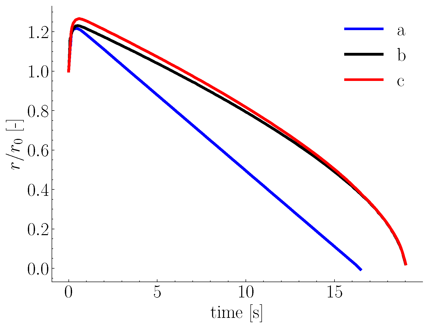
Figure 1. Normalized particle radius (initial radius 0.975 cm and initial temperature 25 °C) of a single sphere showing shell formation in quiescent melt at 700 °C. Line (a) constant thermophysical properties and heat transfer coefficient, line (b) constant thermophysical properties and varying heat transfer as function of radius, and line (c) varying thermophysical properties and heat transfer coefficient (Adapted with permission from Ref. [40]. Copyright 2019 Springer Nature).
Metals 15 00866 g001
Figure 2. Mass-based normalized melting profiles of (a) round and (b) square steel bars, both at initial temperature of 25 °C and at different melt temperatures (Adapted with permission from Ref. [48]. Copyright 2020 Sage Publications).
Metals 15 00866 g002
Figure 3. (a) Radius-based normalized melting profiles of steel rods under natural convection at various temperatures, with initial radius r 0 = 1 cm and carbon concentration 4%. Triangles and circles represent experimental data from Penz and Wright, respectively [12,51]. (b) Ablation of steel rods due to natural convection melting at different immersion times (indicated in red), with a bath carbon concentration of approximately 4.5% [52].
Metals 15 00866 g003
Figure 4. Comparison of Nusselt correlations for single spheres as functions of Reynolds number in forced convection regime between (a) Argyropoulos et al. [16], (b) Sideman, and (c) Hsu correlations. Circles and triangles represent experimental data for steel and aluminum, respectively. Adapted with permission from Ref. [16]. Copyright 1996 Elsevier.
Metals 15 00866 g004
Figure 5. Dissolution of 6 mm radius steel rods (composition: C = 0.26 % , M n = 0.7 % , at bath temperature T = 1400   ° C , and carbon concentration C = 4.5 % ) at different nitrogen gas flow rates in (a) 1 kg iron bath and (b) 25 kg iron bath [12].
Metals 15 00866 g005
Figure 6. Melting rods with different stirring modes; (a) rod specification: radius r 0 = 6 mm, composition: C = 0.26 % , M n = 0.7 % , bath specification T = 1400   ° C , C = 4.5 % , and stirring gas is nitrogen [12]. Wei’s rod specification: initial radii ( r 0 ) are 10 and 25 mm, composition: C = 0.45 % , M n = 0.5 % , and molten bath temperature T = 1400   ° C and C = 3.1 % [62]; (b) dimensionless melting profile of rotating (923 rpm) carbon steel rod (radius r 0 = 20 mm) immersed in liquid Fe-C at different molten bath temperatures [49].
Metals 15 00866 g006
Figure 7. (A) Modeling melting of randomly distributed scrap using phase-field method colored by temperature (adapted from [6], Copyright 2008 Springer Nature. The Minerals, Metals & Materials Society and ASM International. Used with permission). (B) Time evolution of Fe x C y particles using (VOF); particles are colored by volume fraction (1 for liquid and 0 for solid) (adapted from [84], copyright 2023, with kind permission from Elsevier).
Metals 15 00866 g007
Figure 8. (a) Non-dimensional temperature distribution of randomly packed sphero-cylinder particles (adapted from [99], copyright 2015, with kind permission from Elsevier). (b) Mean Nusselt number in randomly packed sphero-cylinders obtained from modified Gunn correlation and numerical simulations using cylinder diameter; DNS results are shown by circles, squares, and triangles with different aspect ratios (adapted from [99], copyright 2015, with kind permission from Elsevier).
Metals 15 00866 g008
Table 3. Overview of different levels of CFD modeling characteristics.
MethodAdvantagesLimitations
PR-DNS/IBM- Resolves local transport (heat and mass) phenomena without requiring closure equations.- Computationally demanding.
- Flexible with varying particle stiffness.- Explicit treatment of fluid–particle interactions leads to stiffness problems.
- Non-conforming method; therefore, domain remeshing is not required.- Requires setting particle properties for each particular problem class.
- Useful in obtaining closure relations (e.g., heat or mass coefficients).
CFD-DEM- Accurate solid–fluid dynamics for large numbers of solid particles.- Solution sensitivity to cell size to particle size ratio.
- Moderate computational cost compared to DNS-IBM.- Requires closure correlations for solid–fluid local transport phenomena.
- Applicable to large scales relative to PR-DNS/IBM scale.- Requires parameter calibration.
CFD- Low computational cost compared to CFD-DEM and PR-DNS/IBM.- Packing solids with given porosity is not possible.
- Scalability.- Solid collision and dynamics as results of melting cannot be simulated.
Disclaimer/Publisher’s Note: The statements, opinions and data contained in all publications are solely those of the individual author(s) and contributor(s) and not of MDPI and/or the editor(s). MDPI and/or the editor(s) disclaim responsibility for any injury to people or property resulting from any ideas, methods, instructions or products referred to in the content.