Article

Numerical Simulation of Fluid Flow and Solidification in Round Bloom Continuous Casting with Alternate Final Electromagnetic Stirring

1
School of Metallurgical and Power Engineering, Chongqing University of Science and Technology, Chongqing 401331, China
2
College of Materials Science and Engineering, Chongqing University, Chongqing 400044, China
*
Authors to whom correspondence should be addressed.
Metals 2025, 15(6), 605; https://doi.org/10.3390/met15060605
Submission received: 21 April 2025 / Revised: 20 May 2025 / Accepted: 26 May 2025 / Published: 28 May 2025

Abstract

:
Final electromagnetic stirring (F-EMS) effectively improves macrosegregation and central porosity in round bloom continuous casting, while the flow and solidification of molten steel under F-EMS have a direct impact on metallurgical properties. Fluid flow and solidification behavior in a 600 mm round bloom continuous casting process with F-EMS were simulated. The influence of the liquid fraction model on strand temperature distribution was investigated. The flow of molten steel was analyzed under both continuous and alternate stirring modes. The results indicated that in continuous stirring mode, the stirring velocity fluctuates between peaks and troughs over a specific period. The closer the F-EMS is to the meniscus, the larger the mushy zone area and the higher the stirring velocity. Due to the 10+ s rise time for current intensity, a 25 s forward and reverse stirring duration is recommended for Φ600 mm round bloom continuous casting with F-EMS.

1. Introduction

Final electromagnetic stirring (F-EMS) plays a crucial role in continuous casting by promoting equiaxed grain formation, reducing shrinkage cavities, and mitigating macrosegregation [1,2,3]. Compared with mold and strand EMS, F-EMS directly targets the mushy zone near the final stage of solidification, making it particularly effective for large-section billets [4,5].
Numerical simulations have become indispensable for understanding the coupled multi-physics phenomena involved in F-EMS, such as electromagnetic behavior, fluid flow, heat transfer, solidification, and solute transport. Early studies by Ren et al. [1] and Xu et al. [2] explored the effects of billet size and shell conductivity on the distribution of magnetic field intensity and Lorentz force.
More advanced simulations have integrated electromagnetic, fluid flow, thermal behavior, and solidification into unified numerical models [5,6,7,8]. Jiang et al. [5] found that high-velocity stirring could lead to partial remelting of the solidified shell. Wu et al. [6] introduced thermal stress and crack prediction into the model, revealing that F-EMS helps reduce thermal gradients, stress, and the probability of internal cracking in P91 steel blooms.
Several studies have developed three-dimensional, multi-physics models that couple electromagnetic fields, fluid flow, heat transfer, solidification, and solute transport to investigate the influence of F-EMS on centerline segregation in continuously casting billets and blooms [4,9,10,11,12,13,14,15,16]. Luo et al. [17] and Yin et al. [16] confirmed that increasing the F-EMS current intensity enhances electromagnetic force and melt velocity at the solid–liquid interface, improving solute uniformity in high-carbon steel billets. Sun et al. [11] and Li et al. [14] suggested that the optimal F-EMS installation position depends on the solidification characteristics of the steel and should align the interplay between solidification time and natural convection intensity to minimize segregation. Sun et al. [9] demonstrated that well-designed alternate stirring cycles can effectively reduce centerline carbon segregation while avoiding white bands and shrinkage defects associated with continuous stirring.
Many studies have developed comprehensive multiphase, three-dimensional coupled numerical models that incorporate electromagnetic fields, fluid flow, and heat transfer, explicitly tracking the evolution of solidification structures, including both columnar and equiaxed grains. Wang et al. [18] combined industrial experiments with simulations to demonstrate that coordinated control of solidification structure and F-EMS stirring position can significantly enhance solute homogeneity, especially when stirring occurs within the equiaxed grain zone.
Although widely applied, transient flow and solidification behavior under alternate F-EMS in large-section round blooms have received limited attention. Additionally, the linear approximation of liquid fraction commonly used in mushy zone modeling may oversimplify the actual solidification path [4,7,10], while an equilibrium-based expression provides improved accuracy in capturing latent heat release [19].
The numerical simulation of the electromagnetic field generated by F-EMS has been addressed in our previous study [1]. Building upon this foundation, the present work develops a three-dimensional coupled model of fluid flow and solidification to investigate the influence of various liquid fraction models and F-EMS stirring modes on the thermal and flow fields in a Φ600 mm round bloom. This study aims to provide practical guidance for optimizing F-EMS stirring strategies and installation positions in industrial applications.

2. Mathematical Model

2.1. Basic Assumption

Since fluid flow and solidification behavior in round bloom continuous casting with F-EMS are highly coupled and complex, several assumptions are made to simplify the model.
  • The molten steel is considered as an incompressible Newtonian fluid, the mushy zone is treated as a porous medium, and the liquid flow within it follows Darcy’s law [5,6,7,13,14,16].
  • The time-averaged electromagnetic force is used instead of the instantaneous value as a body force term in the momentum equation.
  • The Joule heat generated by the induced current is negligible and thus neglected in the strand temperature calculation [1].
  • The Boussinesq approximation is applied to account for thermal buoyancy effects due to temperature gradients [13,20].
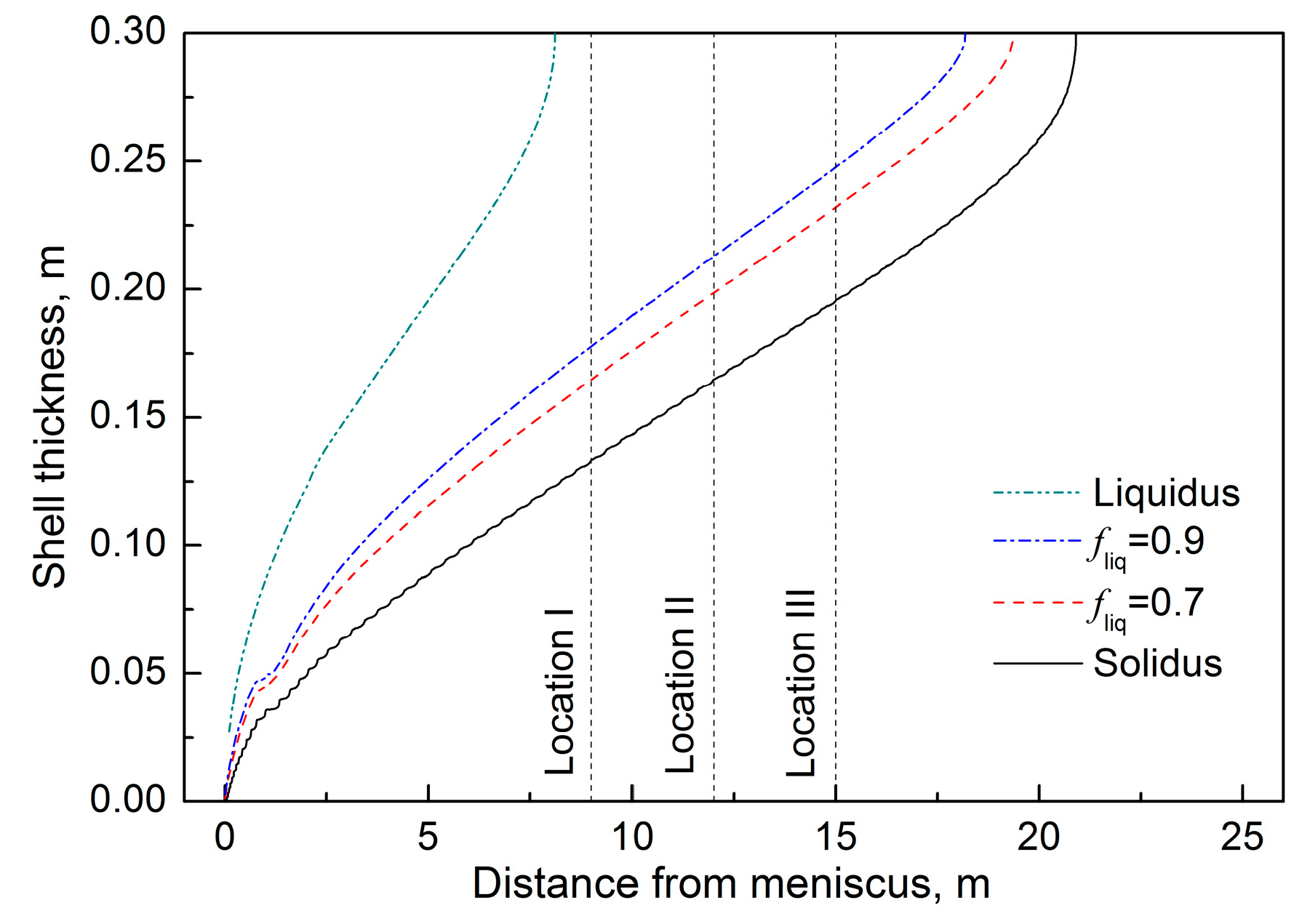
  • Since M-EMS is located far upstream from the F-EMS installation position (12 m from the meniscus), its influence is ignored to reduce computational cost.
  • The curvature of the strand is assumed to be negligible.

2.2. Governing Equations

The governing equations for fluid flow and solidification behavior in continuous casting blooms with EMS are as follows: the continuity equation, momentum equation, energy equation, and low Reynolds number turbulence model. Detailed descriptions of these equations can be found in our previous work [21,22]. This study primarily focuses on the expression of the liquid fraction in both the energy equation and the Navier–Stokes equation.
Latent heat significantly affects the temperature distribution and solidification process inside the strand, and its release is reflected in the relationship between the liquid fraction and temperature. The following two latent heat release modes are commonly used in numerical simulations.

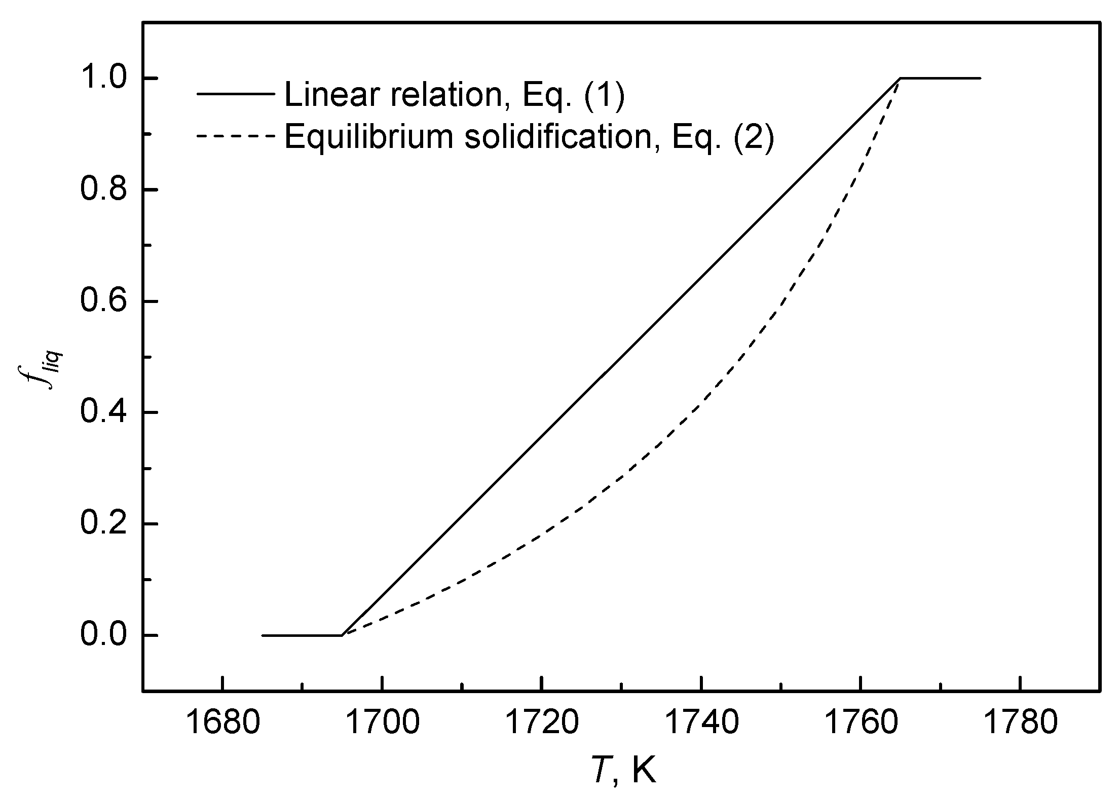
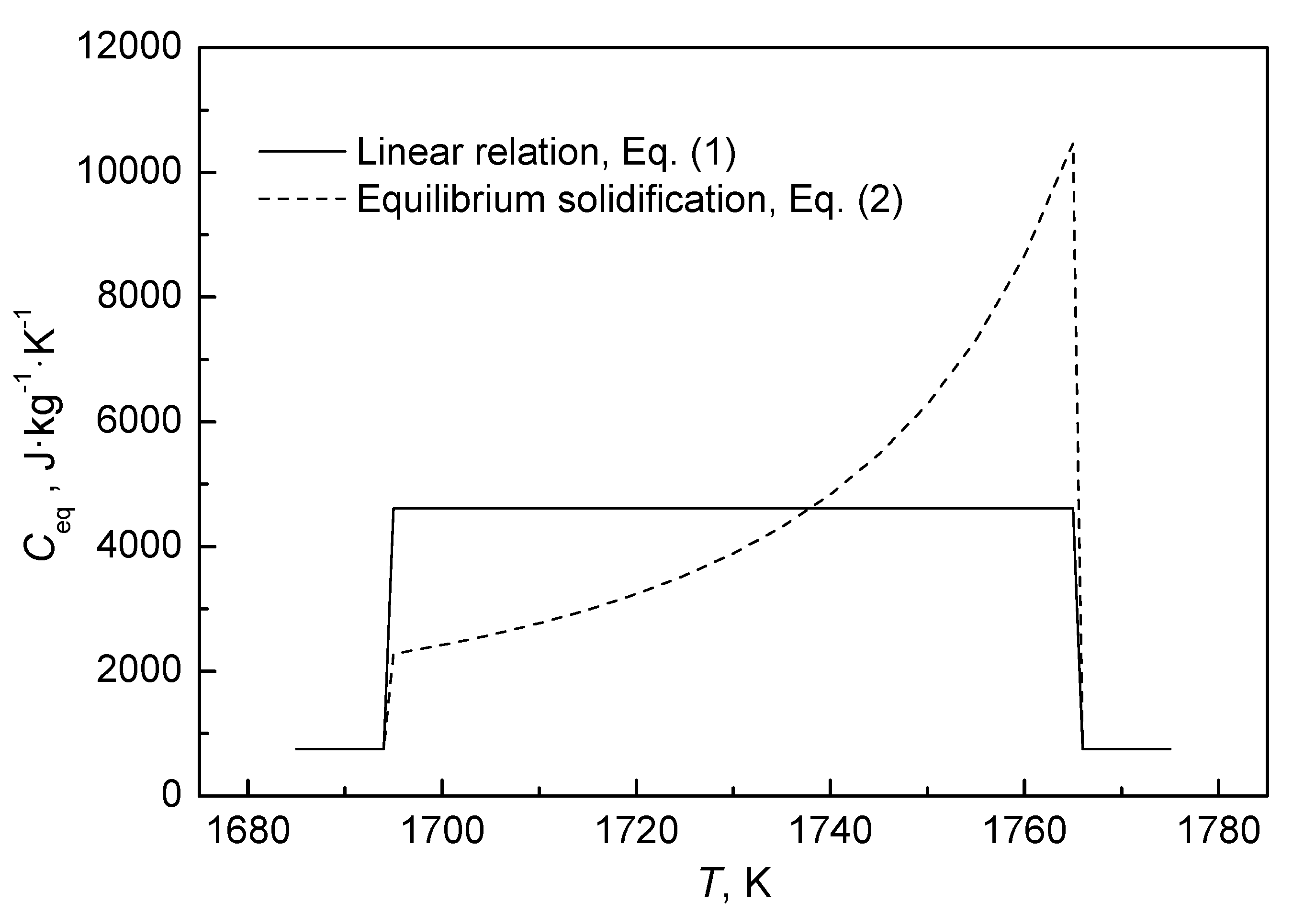
2.2.1. Linear Relationship

It is assumed that the liquid fraction fliq is linear with temperature between the liquidus temperature Tliq and the solidus temperature Tsol, which can be expressed as follows [4,7,10,12,16,20]:
f l i q = T T s o l T l i q T s o l

2.2.2. Equilibrium Expression

It is assumed that the solidification process occurs very slowly, ensuring that it is always in an equilibrium state between the solid and liquid phases. Thus, the lever rule can be used to determine the relationship between fliq and the temperature according to the phase diagram [19], as follows:
f l i q = 1 1 1 k 0 T T l i q T T m e l t
where Tmelt is the melting point of the pure solvent metal and k0 is the partition coefficient of the Fe-C alloy. When the solidus and liquidus are straight lines,
k 0 = T m e l t T l i q T m e l t T s o l
Figure 1 compares the relationship between liquid fraction and temperature in these two modes, using 45 steel as an example. The relationship between the liquid fraction and the temperature in the equilibrium solidification mode is similar to a parabola, which is very different from the linear relationship.
The difference in the effects of the above two expressions on strand solidification can be understood in terms of the equivalent specific heat. The amount of heat released per unit mass of metal per unit temperature within the solidification temperature range is defined as the equivalent specific heat Ceq.
The enthalpy H is decomposed into sensible heat and latent heat as follows:
H = h r e f + T r e f T C P dT + f l i q L
where href is the reference enthalpy, Tref is the reference temperature, Cp is the specific heat, and L is the latent heat.
Taking the derivative of Equation (4) with respect to temperature yields
C e q = dH dT = C p + df l i q dT L
In the linear relationship (Equation (1)), the equivalent specific heat is expressed as
C e q = C p + L T l i q - T s o l
In the equilibrium relationship (Equation (2)), the equivalent specific heat is expressed as
C e q = C p + T m e l t - T l i q L 1 k 0 T m e l t - T 2
Figure 2 shows the relationship between equivalent specific heat and temperature in the two modes, illustrating the heat release process. It can be shown that in the linear relationship, the heat is uniformly released in the solidification temperature range; in the equilibrium solidification mode, the heat released is large at the initial solidification stage and then gradually decreases, which is in accordance with the solidification of the actual liquid steel. Although the total amount of latent heat released is the same in both modes, the difference in the latent heat release process significantly affects the temperature distribution inside the strand.

2.3. Boundary Conditions

The Φ600 mm round bloom studied here is produced in a domestic steel mill. The calculated strand length is 22 m, assuming an average casting speed of 0.28 m/min. The length of the cooling zone for the Φ600 mm round bloom caster is shown in Table 1. F-EMS was installed in the caster and operated at 400 A and 4 Hz.
The molten steel velocity at the submerged entry nozzle (SEN) inlet was calculated based on the casting speed, according to mass conservation principles [22]. The velocity at the strand wall was set to the casting speed. The molten steel temperature at the SEN inlet was specified as the sum of the liquidus temperature and superheat. The meniscus and the refractory surface of the SEN are generally considered adiabatic [23]. The heat flux density of the mold was calculated using the actual temperature difference and the water volume in the mold cooling system, which is 0.75 MW/m2. The convective heat transfer boundary was applied to the secondary cooling zone, and the heat transfer coefficient was calculated based on the cooling water quantity and radiation heat transfer [23]. In this paper, the heat transfer coefficients for the water spray zone and air mist cooling zones 1 and 2 are 345 W·m−2·K−1, 235 W·m−2·K−1, and 165 W·m−2·K−1, respectively. The cooling water temperature and ambient temperature are both 298 K. The air cooling zone and the heat insulation zone adopted radiation boundary conditions with a blackness of 0.8, and the ambient temperatures of the two zones are 373 K and 773 K, respectively.

2.4. Thermophysical Properties

The 600 mm round bloom is made of 45 steel (see Table 2), and its thermal and physical properties used in the numerical simulation are provided in Table 3.

2.5. Numerical Solution

The size of the 3D geometrical model is 600 mm × 22 m, covering the entire casting strand from the meniscus to the solidification end. The details of the cooling zone are provided in Table 1. Using ANSYS Fluent 16 software, the time-averaged electromagnetic force density was applied as the source term in the momentum equation, and the finite volume method was used to solve fluid flow and solidification behavior in 600 mm round bloom continuous casting with F-EMS. To improve convergence stability, transient calculations were performed with a time step ranging from 0.05 to 0.1 s. In the transient calculations, the end time for the calculation needs to be determined. In this calculation, the average temperatures at different cross-sections of the round bloom were taken as monitoring points, and their changes over time were observed. When the temperatures at all monitoring points stabilize (see Figure 3), the calculation can be terminated.

3. Results and Discussion

3.1. Model Validation

Figure 4 compares the strand surface temperature predicted by the coupled flow and solidification model with measured data obtained from infrared temperature measurements in the continuous casting of a 600 mm round bloom with F-EMS at a casting speed of 0.28 m/min. The surface temperature of the cast billet drops sharply in the mold area, decreases more gradually in the secondary cooling area, and shows a temperature rebound further downstream. The difference between the two is minimal, which indirectly validates the mathematical model and solution method.

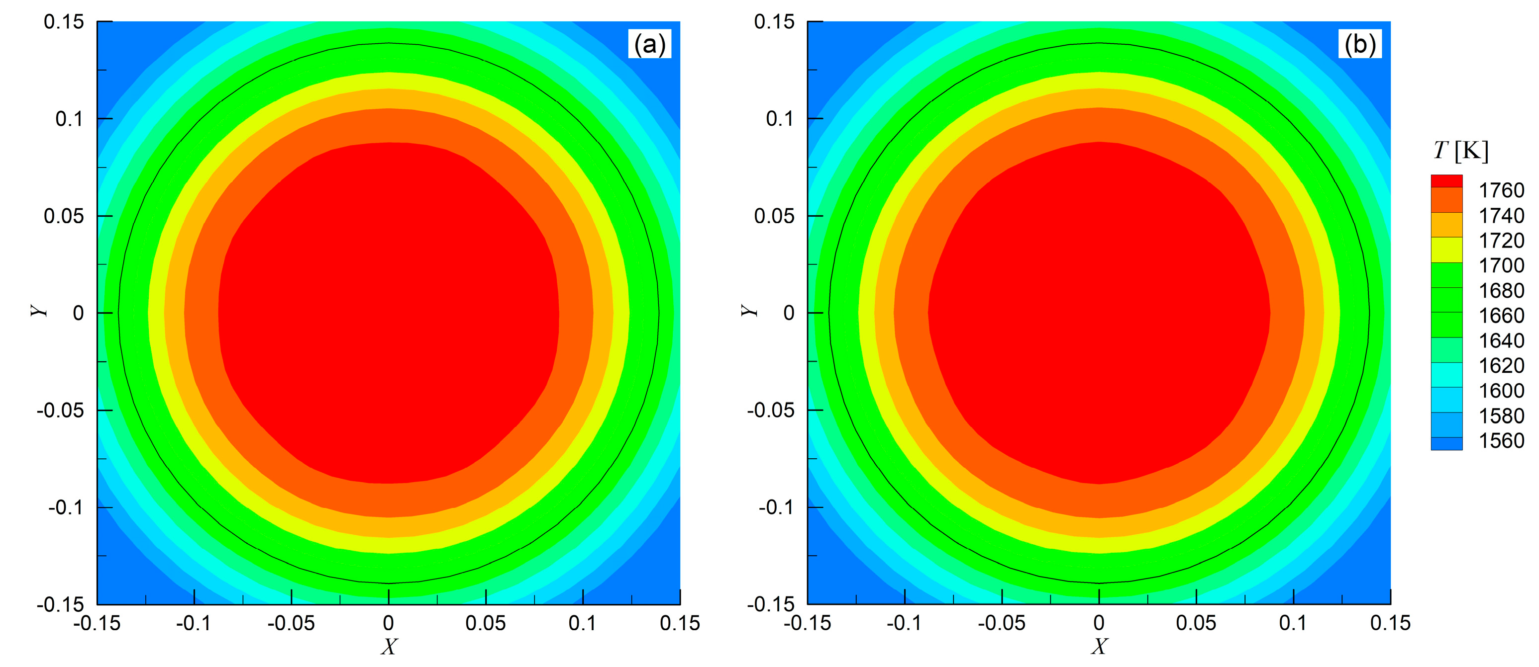
3.2. Effect of Latent Heat Release Model

Figure 5 illustrates the solidification process of the Φ600 mm round bloom under the two latent heat release modes. The difference between the two modes is mainly observed in the liquidus distribution during initial solidification, while the solidus position is nearly identical at the solidification end. This indicates that different latent heat release modes can lead to significant differences in temperature and liquid fractions in the mushy zone, especially for steels with a large temperature gap between the liquidus and solidus. Furthermore, the temperature distribution in the mushy zone directly affects molten steel flow, thereby influencing its flow pattern under F-EMS. Since the equilibrium expression better represents actual molten steel solidification and has a clearer physical basis, it is recommended to use the equilibrium mode to study fluid flow and solidification in Φ600 mm round bloom continuous casting with F-EMS.

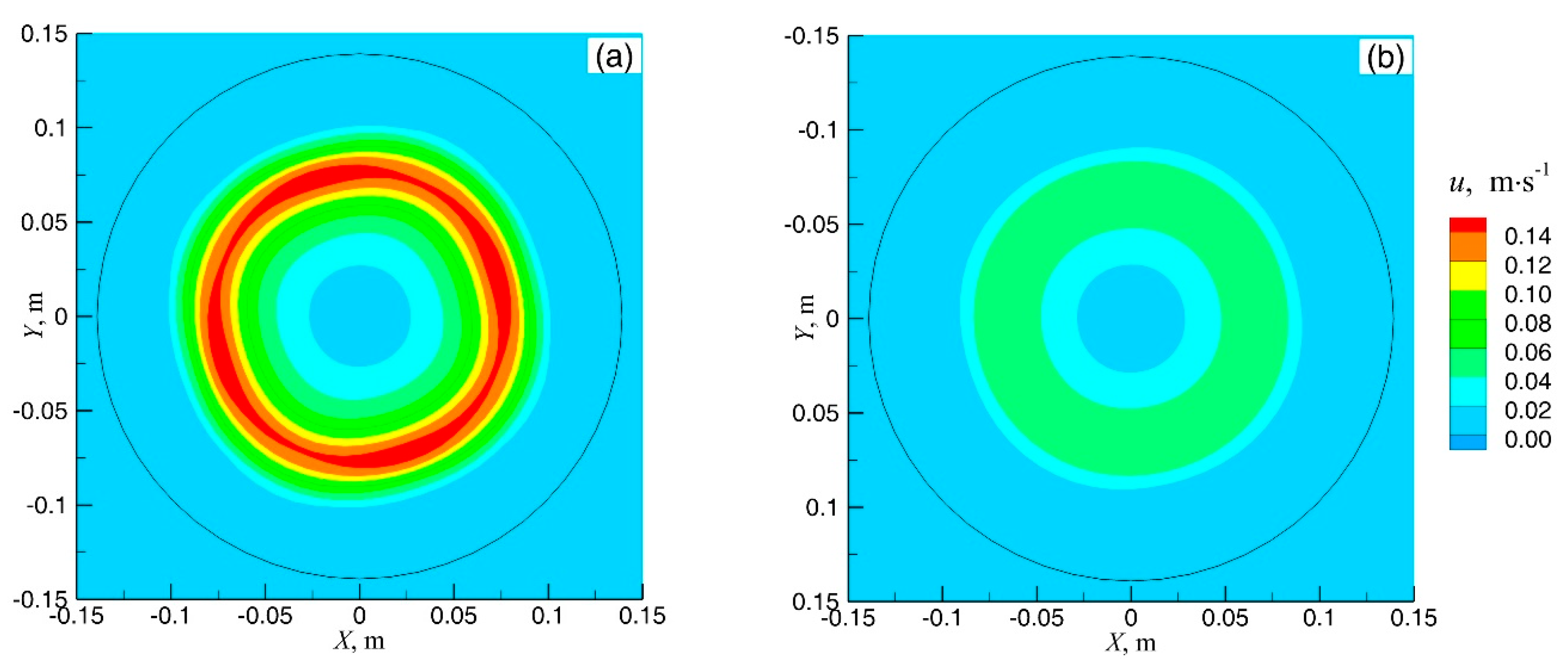
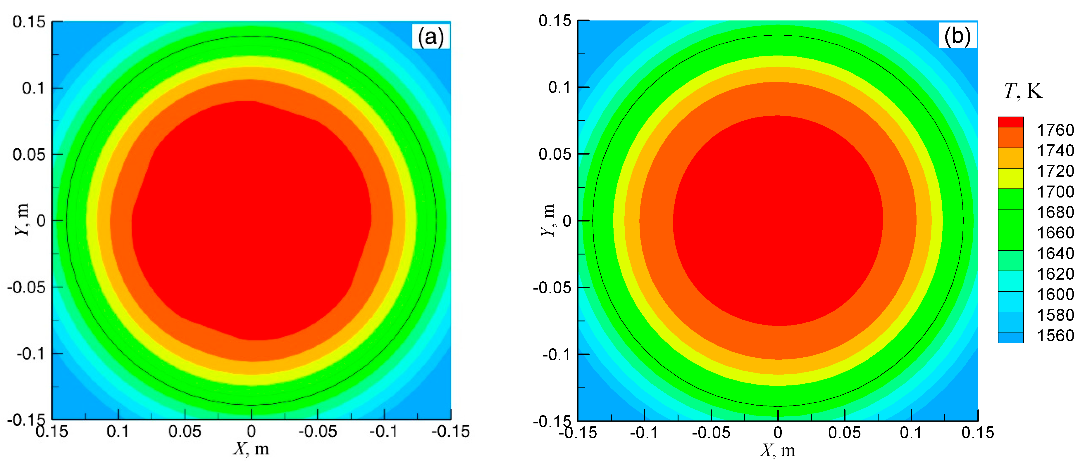
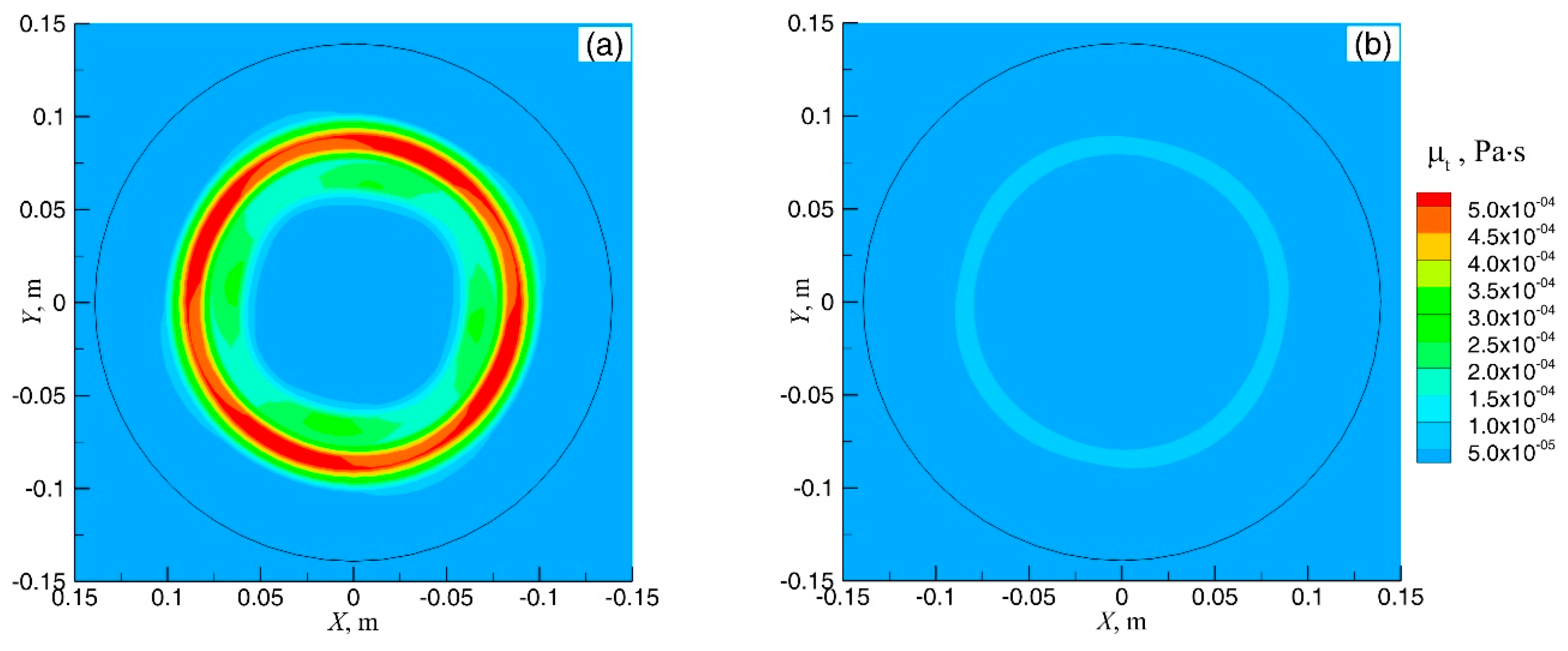
3.3. Flow and Solidification in the Continuous Stirring Mode

Figure 6 displays the solidification characteristics of the Φ600 mm round bloom during continuous casting at a casting speed of 0.28 m/min. In the present study, one of the main purposes was to investigate the effect of F-EMS installation position on the flow and solidification of the strand. Based on the liquidus and solidus profiles (Figure 6), three installation positions were selected for comparison. F-EMS was assumed to be installed at 9 m (Location I), 12 m (Location II), or 15 m (Location III) from the meniscus.
The maximum velocity of molten steel in the stirrer’s mid-plane is used to evaluate F-EMS stirring intensity, referred to as the maximum stirring velocity. Figure 7 shows that the maximum stirring velocity of molten steel in the stirrer’s mid-plane varies with time under the three F-EMS installation positions. With F-EMS applied, the maximum stirring velocity is high—reaching up to 0.77 m/s at Location I—but it decreases rapidly. Notably, regardless of the F-EMS position, the maximum stirring velocity exhibits periodic variation between peaks and troughs.
Figure 8, Figure 9 and Figure 10 show contour plots of stirring velocity, temperature, and turbulent viscosity of molten steel in the stirrer’s mid-plane at moments of maximum stirring velocity—at both peaks and troughs—when F-EMS is installed at Location II (Z = 12 m). To observe the mushy zone more clearly, only a 150 mm × 150 mm area at the center of the 600 mm round bloom is shown. The solid black circle in each figure represents the solidus. The values of stirring velocity, temperature, and turbulent viscosity at the velocity peaks are higher than those at the troughs. This periodic variation arises from interactions among thermal evolution, fluid flow, and latent heat release in the mushy zone. At high local temperatures, a larger liquid fraction reduces flow resistance, enhancing stirring velocity and turbulent viscosity. This promotes heat extraction and reduces temperature, thereby shrinking the liquid fraction and increasing flow resistance. As a result, stirring weakens until the temperature rises again, forming a feedback loop that drives the velocity oscillation pattern. Additionally, as shown in Figure 8a, the region of maximum velocity is separated from the solidus, creating a stagnant zone between the high-velocity core and the solid phase. This occurs because molten steel loses fluidity when the liquid fraction falls below 0.3, not only when fliq = 0 [24,25].
Figure 11 shows the longitudinal velocity distribution for the three F-EMS positions. It is evident that the closer F-EMS is to the meniscus, the wider the mushy zone and the higher the resulting stirring velocity. According to previous studies [14,26], effective metallurgical stirring requires velocities in the mushy zone to remain within 0.1–0.2 m/s. Therefore, placing the F-EMS at 12 m is suitable for the 600 mm round bloom, as it aligns with the liquid core region, where flowability is sufficient, and falls within the equiaxed grain growth zone—both of which are favorable for macrosegregation control.

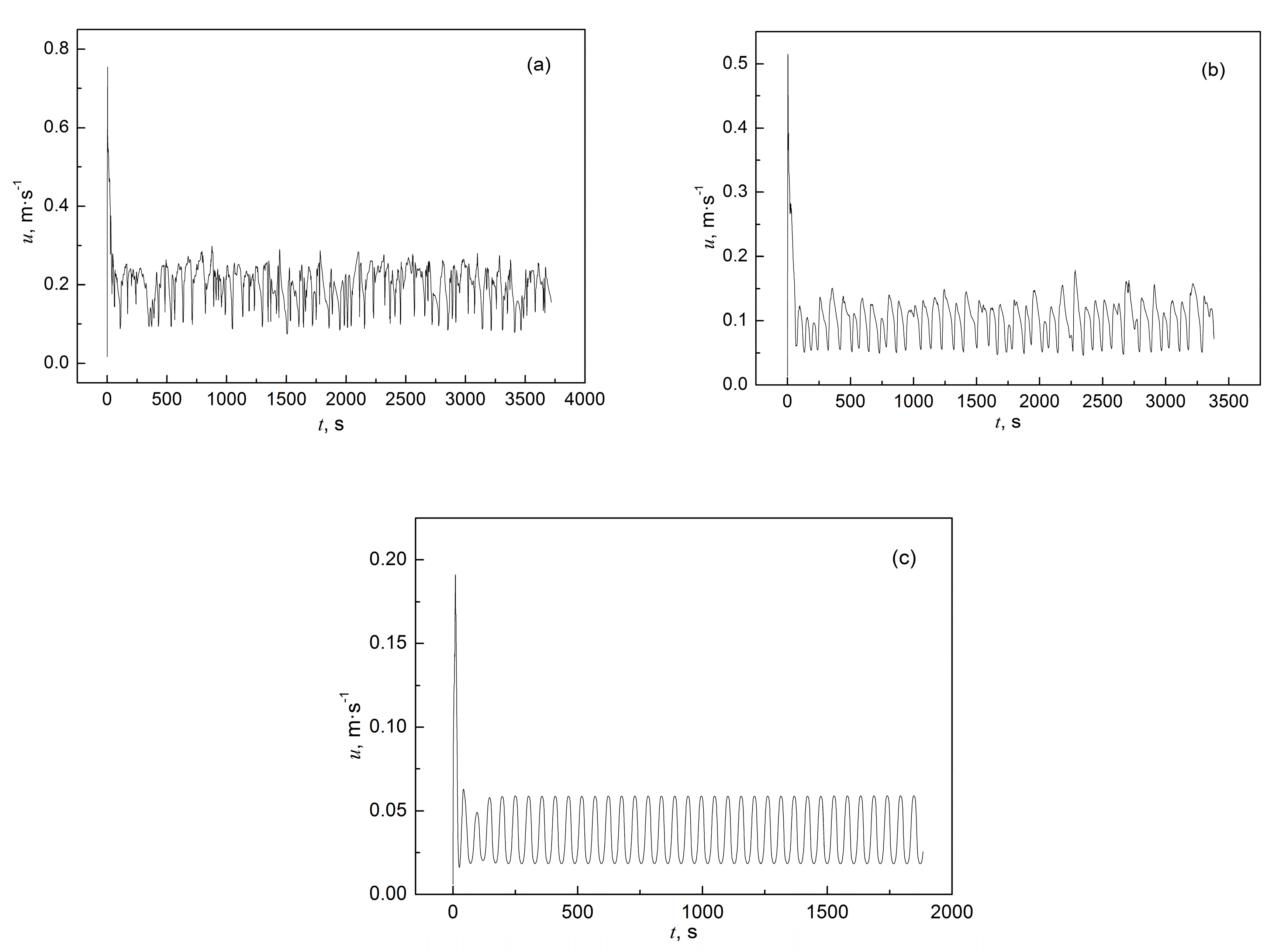
3.4. Flow and Solidification in the Alternate Stirring Mode

In actual continuous casting, applying F-EMS in continuous mode may lead to a severe negative segregation band (commonly referred to as a “white band”) [27,28,29], which can adversely affect the strand’s mechanical properties. To mitigate this, the alternate stirring mode—consisting of forward stirring, pause, reverse stirring, and pause—is commonly used, as shown in Figure 12a.
However, the actual current response is slower than the ideal case, requiring noticeable time for the intensity to rise from 0 A to the target value, as shown in Figure 12b. The alternate stirring mode in Figure 12b consists of 25 s forward stirring, 5 s stop, and 25 s reverse stirring. It takes approximately 10 s to reach 360 A and about 17 s to reach 400 A. Although previous studies suggested 10–15 s stirring durations [30], this is insufficient for Φ600 mm round blooms, as the current does not reach the intended 400 A within that time. Therefore, the recommended alternate stirring cycle for 600 mm round bloom casting with F-EMS is 25 s forward—5 s stop—25 s reverse [9].
Figure 13 shows the variations in stirring velocity under a 400 A current for both ideal and practical alternate stirring modes. The peak stirring velocity reaches approximately 0.15 m/s in both cases; however, the effective flow duration is longer in the ideal mode due to the faster current rise time. This suggests that for large-section blooms, a longer stirring period is required to allow the stirring intensity to develop fully within each cycle. Furthermore, alternate stirring helps disrupt thermal–solutal coupling in the mushy zone, reducing the risk of steady segregation band formation. This dynamic flow variation also promotes a more uniform solute distribution, which is essential for improving macrosegregation control and enhancing the final product’s mechanical properties.
In the actual alternating stirring mode, Figure 14, Figure 15 and Figure 16 compare the velocity, temperature, and liquid fraction fields during forward rotation and after the stirrer stops. When the stirrer rotates forward, the electromagnetic force induces strong rotational and vortical flow in the molten steel. Once the stirring stops, the flow velocity drops almost immediately due to the loss of driving force. This periodic application and removal of the electromagnetic force causes significant changes in the local flow field. During stirring, the molten steel receives strong momentum input, rapidly establishing a coherent flow pattern. After the force is removed, the flow decays rapidly under viscous resistance and the damping effect of the mushy zone, as shown in Figure 14. Consequently, the flow field undergoes continuous reconstruction and dissipation, leading to pronounced periodic fluctuations in velocity. This reduction in stirring intensity can help alleviate negative segregation, such as white bright bands, in the final product.
The alternating stirring also affects the heat transfer regime within the cast slab. When stirring is active, intense convection promotes temperature homogenization in the mushy zone and enhances heat dissipation to the bloom surface. When stirring ceases, convective effects vanish and heat transfer is limited to conduction through the solidified shell, worsening thermal efficiency. This results in a localized temperature rise in the mushy zone and a corresponding increase in liquid fraction, as shown in Figure 15 and Figure 16.
Overall, the start–stop operation of alternate F-EMS introduces nonlinear oscillations in the transport behavior of the system. Each stirring phase enhances convective cooling, lowering mushy zone temperature and liquid fraction. Each pause allows heat accumulation, raising both temperature and liquid fraction. These cyclic fluctuations lead to a complex, nonlinear coupling between the flow, thermal, and solidification fields.

4. Conclusions

In this study, fluid flow and solidification behavior in 600 mm round bloom continuous casting with F-EMS were simulated. The effects of the F-EMS installation position and stirring mode on fluid flow and solidification in the stirring zone were investigated, leading to the following conclusions:
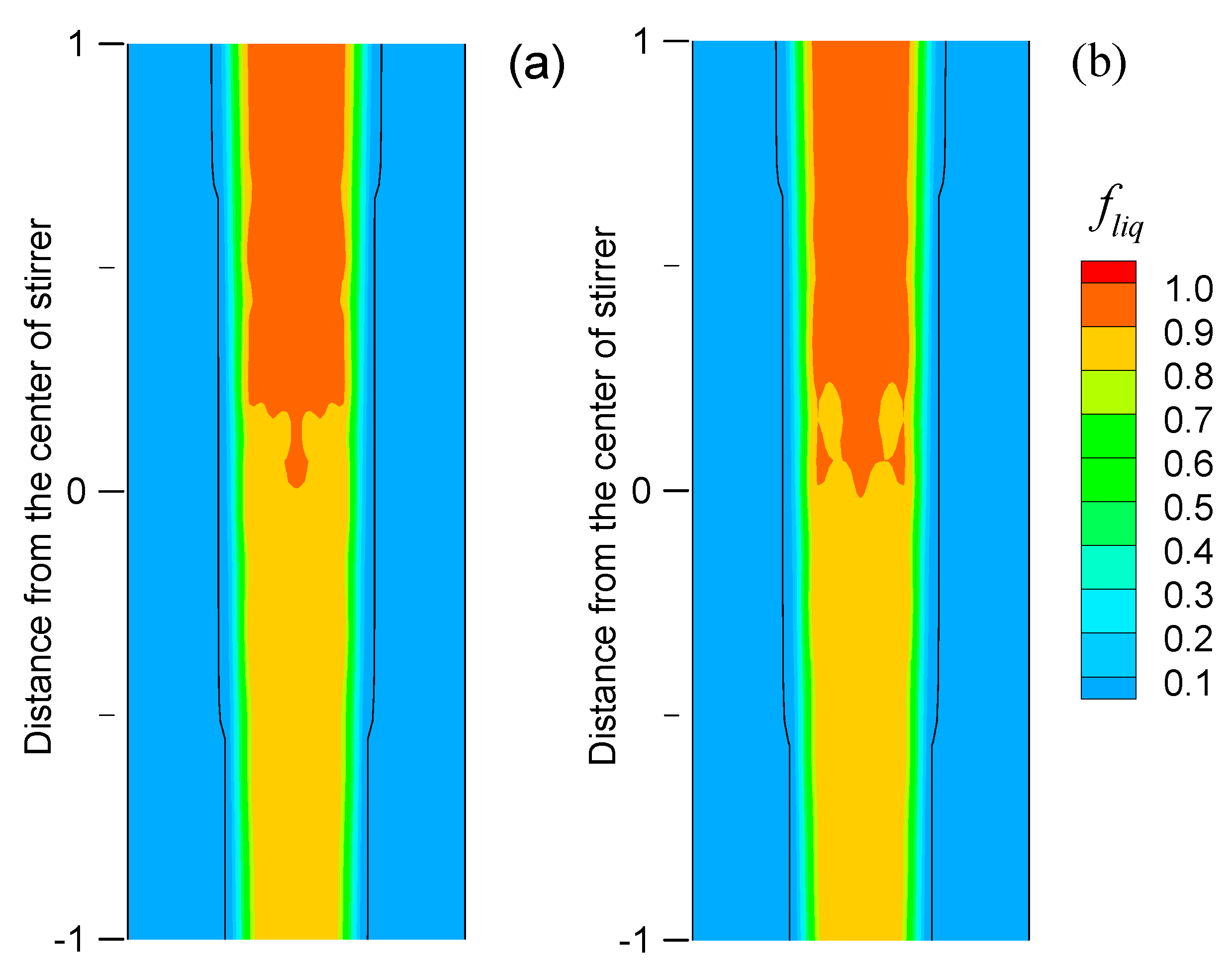
  • In the simulation, the expression of liquid fraction significantly influences the mushy zone, and the equilibrium solidification mode is recommended, as it better reflects actual molten steel behavior.
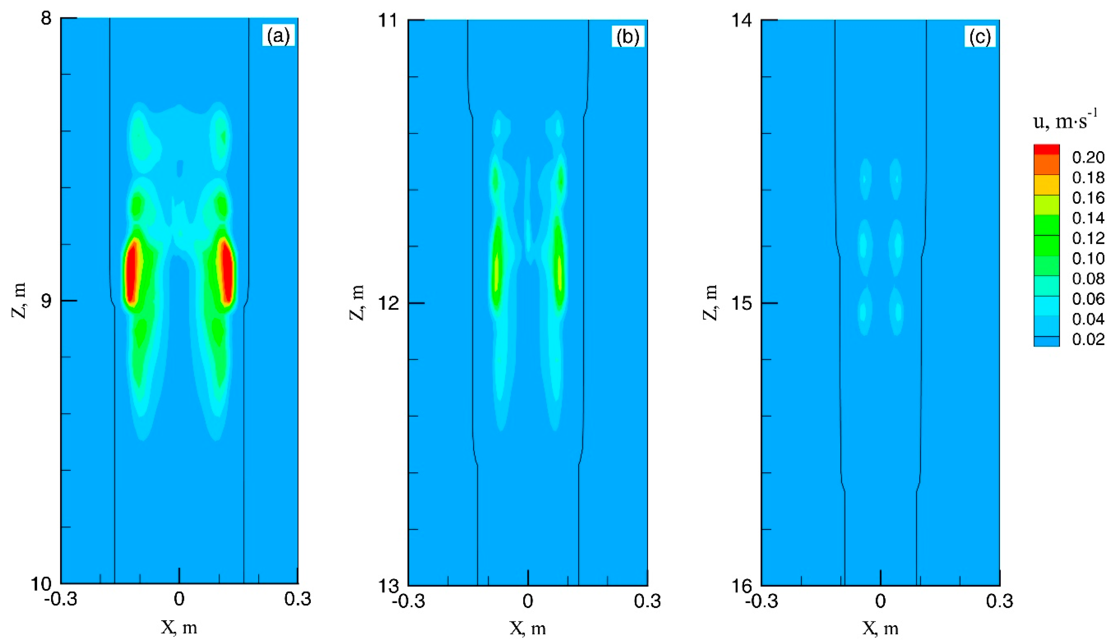
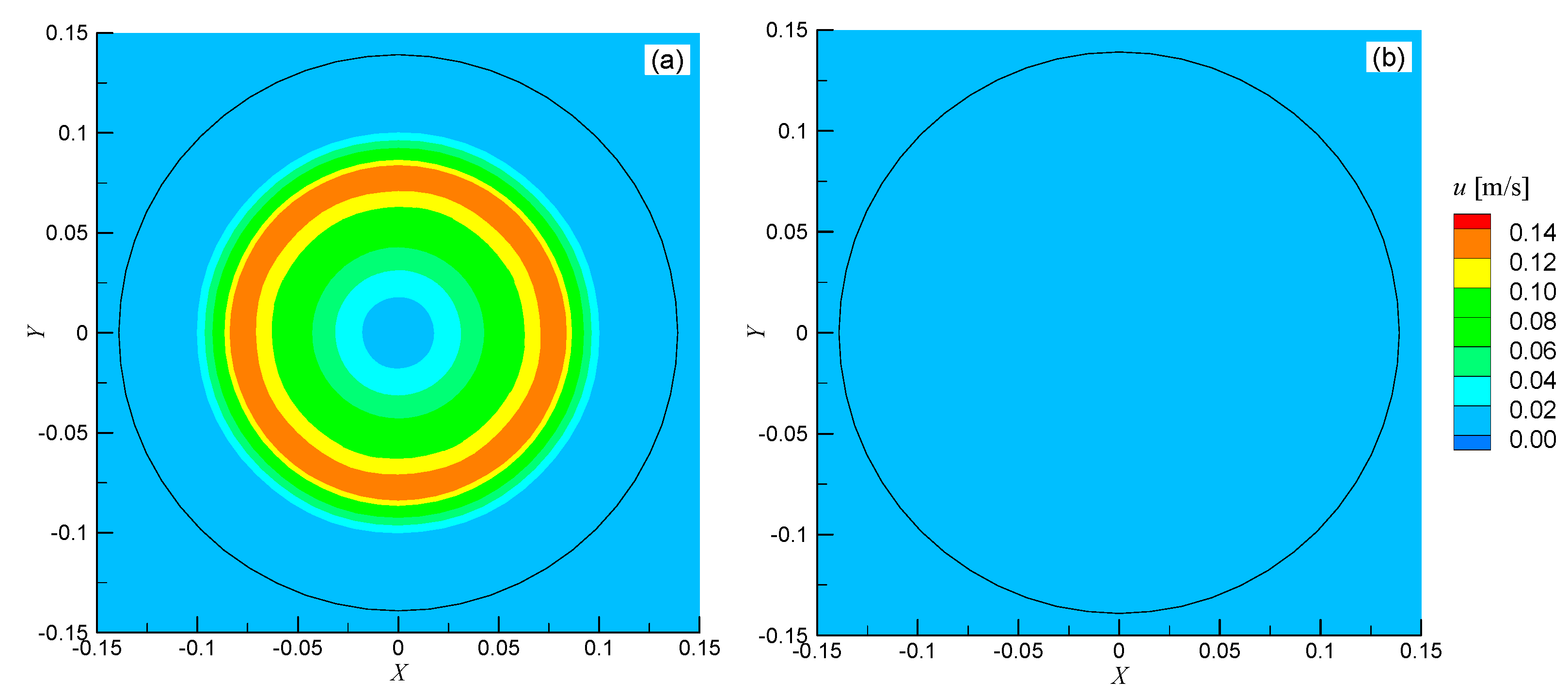
  • The closer the F-EMS installation is to the meniscus, the greater the stirring velocity of molten steel, owing to the wider mushy zone.
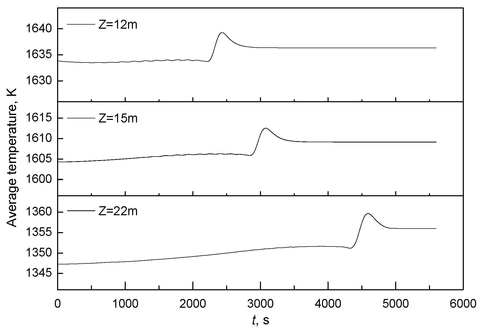
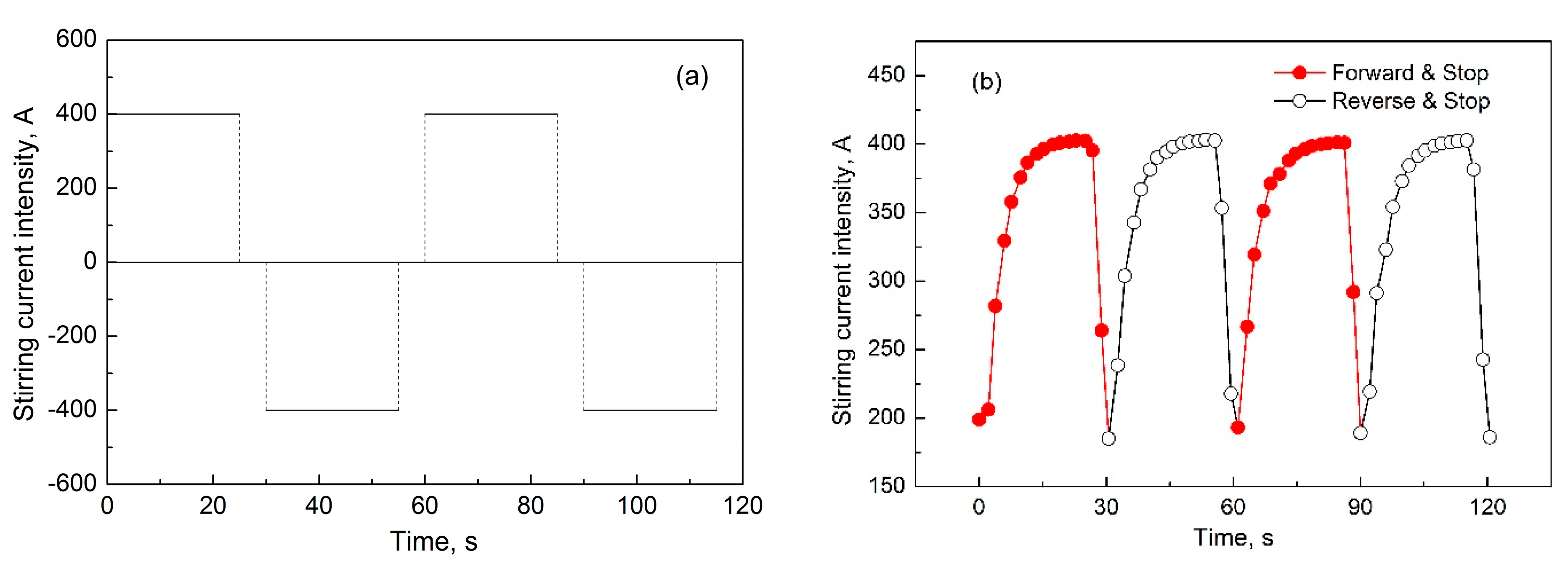
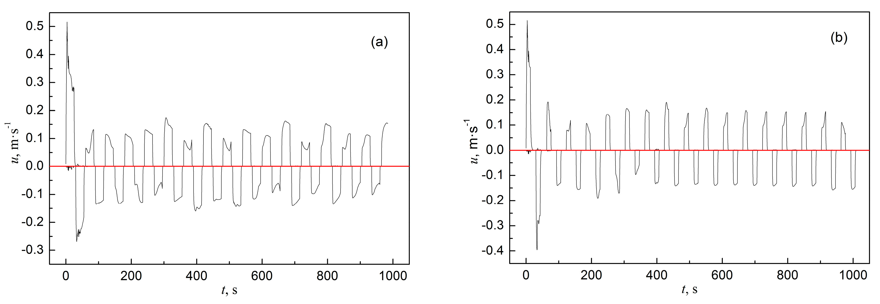
  • In the alternate stirring mode, the actual current rise time exceeds 10 s, making short stirring cycles insufficient for large-section blooms. Based on simulation results and practical considerations, a 25 s forward and reverse stirring duration is recommended for Φ600 mm round bloom casting with F-EMS. This cycle allows sufficient development of stirring intensity, enhances flow stability, improves heat transfer and liquid fraction uniformity in the mushy zone, and helps mitigate negative segregation.
Future work should focus on integrating a solute transport model to better quantify centerline macrosegregation and further validate the results through nail-shooting or macro-etching experiments, which would provide valuable insights into refining the casting process.

Author Contributions

Conceptualization, D.C.; methodology, L.Z.; software, B.R. and H.W.; validation, B.R. and L.Z.; formal analysis, B.R.; investigation, B.R. and H.W.; resources, B.R.; data curation, B.R.; writing—original draft preparation, B.R.; writing—review and editing, H.W.; visualization, B.R. and L.Z.; supervision, D.C.; project administration, D.C.; funding acquisition, B.R., L.Z. and H.W. All authors have read and agreed to the published version of the manuscript.

Funding

The authors are grateful for the support from the National Natural Science Foundation of China (52004049), the Natural Science Foundation of Chongqing, China (Project Number: cstc2020jcyj-msxmX0605, cstc2021jcyj-msxmX0573 and cstc2021jcyj-msxmX0743), and the Science and Technology Research Program of Chongqing Education Commission of China (No. KJQN202201531).

Data Availability Statement

The original contributions presented in this study are included in the article. Further inquiries can be directed to the corresponding authors.

Conflicts of Interest

The authors declare no conflicts of interest.

References

  1. Ren, B.; Chen, D.; Xia, W.; Wang, H.; Han, Z. Numerical Simulation of Electromagnetic Field in Round Bloom Continuous Casting with Final Electromagnetic Stirring. Metals 2018, 8, 903. [Google Scholar] [CrossRef]
  2. Xu, G.; Tan, R.; Song, B.; Liu, W.; Yang, S.; Zuo, X.; Huang, Y. Numerical Simulation of the Effect of Solidified Shell Conductivity and Billet Sizes on the Magnetic Field with Final Electromagnetic Stirring in Continuous Casting. Materials 2023, 16, 4765. [Google Scholar] [CrossRef]
  3. Guo, Q.; Sha, M.; Jia, J.; Zhu, X.; Zou, H.; Cai, L. Effect of Final EMS on Shrinkage Cavity of Bloom. J. Iron Steel Res. Int. 2015, 22, 93–97. [Google Scholar] [CrossRef]
  4. Jiang, D.; Zhu, M. Flow and Solidification in Billet Continuous Casting Machine with Dual Electromagnetic Stirrings of Mold and the Final Solidification. Steel Res. Int. 2015, 86, 993–1003. [Google Scholar] [CrossRef]
  5. Jiang, W.; Long, M.; Liu, T.; Chen, D.; Chen, H.; Cao, J.; Fan, H.; Yu, S.; Duan, H. Fluid Flow and Solidified Shell Remelting in F-EMS During Billet Continuous Casting. JOM 2018, 70, 2059–2064. [Google Scholar] [CrossRef]
  6. Wu, H.; Lei, C.; Xu, C.; Wang, T.; Liu, N.; Ma, G. Effect of Final Electromagnetic Stirring on Internal Thermal Stress, Strain and Cracking of Continuous Casting Bloom. ISIJ Int. 2023, 63, 1373–1382. [Google Scholar] [CrossRef]
  7. Wang, Z.; Wang, E.; Fautrelle, Y.; Zhai, Z. Numerical Simulation of Melt Flow, Heat Transfer and Solidification in Final Solidification Zone of Bloom Continuous Casting with Vertical Linear Electromagnetic Stirring. Metall. Mater. Trans. B 2024, 55, 1482–1496. [Google Scholar] [CrossRef]
  8. Wu, H.J.; Xu, C.J.; Jin, H.Y.; Gao, Y.L.; Zhang, X.B.; Jin, Y.K. Effect of Different Positions of Final Electromagnetic Stirring for Φ800mm Vertical Round Billet on Fluid Flow and Heat Transfer. Appl. Phys. A 2022, 128, 108. [Google Scholar] [CrossRef]
  9. Sun, H.; Li, L.; Ye, D.; Wu, X. On the Alternate Stirring Mode of F-EMS for Bloom Continuous Castings. Metall. Mater. Trans. B 2018, 49, 1909–1918. [Google Scholar] [CrossRef]
  10. Feng, Z.; Zhang, G.; Li, P.; Yan, P. Numerical Simulation of Fluid Flow, Solidification, and Solute Distribution in Billets under Combined Mold and Final Electromagnetic Stirring. Materials 2024, 17, 530. [Google Scholar] [CrossRef]
  11. Sun, H.; Li, L.; Cheng, X.; Qiu, W.; Liu, Z.; Zeng, L. Reduction in Macrosegregation on 380 Mm×490 Mm Bloom Caster Equipped Combination M+F-EMS by Optimising Casting Speed. Ironmak. Steelmak. 2015, 42, 439–449. [Google Scholar] [CrossRef]
  12. Feng, Z.; Zhang, G.; Li, P.; Yan, P.; McLean, A. Improvement of Carbon Segregation in Billet by Final-EMS, Based on Segmented Continuous Casting Model. Ironmak. Steelmak. Process. Prod. Appl. 2024, 51, 112–121. [Google Scholar] [CrossRef]
  13. Jiang, D.; Zhu, M. Center Segregation with Final Electromagnetic Stirring in Billet Continuous Casting Process. Metall. Mater. Trans. B 2017, 48, 444–455. [Google Scholar] [CrossRef]
  14. Li, S.; Han, Z.; Zhang, J. Numerical Modeling of the Macrosegregation Improvement in Continuous Casting Blooms by Using F-EMS. JOM 2020, 72, 4117–4126. [Google Scholar] [CrossRef]
  15. Fang, Q.; Zhang, H.; Wang, J.; Zhao, P.; Wu, G.; Ni, H. Effect of Final Electromagnetic Stirring on Flow, Solidification, and Solute Transport in Continuous Casting Bloom. JOM 2021, 73, 2698–2708. [Google Scholar] [CrossRef]
  16. Yin, S.; Luo, S.; Zhang, W.; Wang, W.; Zhu, M. Numerical Simulation of Macrosegregation in Continuously Cast Gear Steel 20CrMnTi with Final Electromagnetic Stirring. J. Iron Steel Res. Int. 2021, 28, 424–436. [Google Scholar] [CrossRef]
  17. Luo, S.; Piao, F.; Jiang, D.; Wang, W.; Zhu, M. Numerical Simulation and Experimental Study of F-EMS for Continuously Cast Billet of High Carbon Steel. J. Iron Steel Res. Int. 2014, 21, 51–55. [Google Scholar] [CrossRef]
  18. Wang, P.; Chen, L.; Ma, Z.; Shao, J.; Jiang, C.; Zhang, B.; Zhang, J. Improving Compositional Homogeneity of CF53 Steel Products by Modifying Their Solidification Structure and F-EMS Intensity. Ironmak. Steelmak. Process. Prod. Appl. 2024, 51, 228–237. [Google Scholar] [CrossRef]
  19. Jiang, M.; Xu, D.; Ya, B.; Meng, L.; Zhu, M.; Shan, C.; Zhang, X. Effect of Electromagnetic Power on the Microstructure and Properties of 2219 Aluminum Alloy in Electromagnetic Continuous Casting Technology. Metals 2024, 14, 393. [Google Scholar] [CrossRef]
  20. Xie, Q.; Ni, P.; Ersson, M.; Liu, Q.; Li, Y. Effect of Swirling Flow Submerged Entry Nozzle on Solidification and Macrosegregation Behavior of a Round Bloom with Mold and Final Electromagnetic Stirring. Metall. Mater. Trans. B 2025, 56, 154–169. [Google Scholar] [CrossRef]
  21. Ren, B.-Z.; Chen, D.-F.; Wang, H.-D.; Long, M.-J.; Han, Z.-W. Numerical Simulation of Fluid Flow and Solidification in Bloom Continuous Casting Mould with Electromagnetic Stirring. Ironmak. Steelmak. 2015, 42, 401–408. [Google Scholar] [CrossRef]
  22. Ren, B.; Chen, D.; Wang, H.; Long, M. Numerical Analysis of Coupled Turbulent Flow and Macroscopic Solidification in a Round Bloom Continuous Casting Mold with Electromagnetic Stirring. Steel Res. Int. 2015, 86, 1104–1115. [Google Scholar] [CrossRef]
  23. Sun, H.; Zhang, J. Study on the Macrosegregation Behavior for the Bloom Continuous Casting: Model Development and Validation. Metall. Mater. Trans. B 2014, 45, 1133–1149. [Google Scholar] [CrossRef]
  24. Wang, X.; Shu-guo, Z.; Zhu, M. Fluid Flow, Solidification and Solute Transport in Billet Continuous Casting with Different Stirrer Positions. Ironmak. Steelmak. 2022, 49, 343–353. [Google Scholar] [CrossRef]
  25. Flemings, M.C. Behavior of Metal Alloys in the Semisolid State. Metall. Trans. B 1991, 22, 269–293. [Google Scholar] [CrossRef]
  26. Mizukami, H.; Komatsu, M.; Kitagawa, T.; Kawakami, K. Effect of Electromagnetic Stirring at the Final Stage of Solidification of Continuously Cast Strand. Trans. Iron Steel Inst. Jpn. 1984, 24, 923–930. [Google Scholar] [CrossRef]
  27. Xu, Y.; Xu, R.; Fan, Z.; Li, C.; Deng, A.; Wang, E. Analysis of cracking phenomena in continuous casting of 1Cr13 stainless steel billets with final electromagnetic stirring. Int. J. Miner. Metall. Mater. 2016, 23, 534–541. [Google Scholar] [CrossRef]
  28. Jiang, D.; Wang, R.; Zhang, Q.; Zhang, Z.; Tu, T.; Wang, J.; Ren, Z. Effect of Final Electromagnetic Stirring on Solidification Microstructure of GCr15 Bearing Steel in Simulated Continuous Casting. J. Iron Steel Res. Int. 2020, 27, 141–147. [Google Scholar] [CrossRef]
  29. Kovačič, M.; Župerl, U. Continuous Caster Final Electromagnetic Stirrers Position Optimization Using Genetic Programming. Mater. Manuf. Process. 2023, 38, 2009–2017. [Google Scholar] [CrossRef]
  30. Mao, B.; Li, A. Theory and Technology of Electromagnetic Stirring for Continuous Casting; Metallurgical Industry Press: Beijing, China, 2012. [Google Scholar]
Figure 1. Comparison of liquid fraction models.
Metals 15 00605 g001
Figure 2. Equivalent specific heat distributions in the two models.
Metals 15 00605 g002
Figure 3. Instantaneous average temperature at different cross-sections of the Φ600 mm round bloom in continuous casting with F-EMS.
Metals 15 00605 g003
Figure 4. Comparison of simulated and measured strand surface temperature.
Metals 15 00605 g004
Figure 5. Solidification front comparison between the two models: (a) liquidus; (b) solidus.
Metals 15 00605 g005
Figure 6. Solidification characteristic of the Φ600 mm round bloom in continuous casting at a casting speed of 0.28 m·min−1.
Metals 15 00605 g006
Figure 7. Time evolution of maximum stirring velocity under different F-EMS positions: (a) Location I; (b) Location II; (c) Location III.
Metals 15 00605 g007
Figure 8. Contour plots of the stirring velocity of liquid steel in the middle plane of the stirrer at the moment of maximum stirring velocity: (a) at the peaks; (b) at the troughs. (The solid black circle represents the solidus, as with the figure below).
Metals 15 00605 g008
Figure 9. Contour plots of the temperature in the middle plane of the stirrer at the moment of maximum stirring velocity: (a) at the peaks; (b) at the troughs.
Metals 15 00605 g009
Figure 10. Contour plots of the turbulent viscosity in the middle plane of the stirrer at the moment of maximum stirring velocity: (a) at the peaks; (b) at the troughs.
Metals 15 00605 g010
Figure 11. Contour plots of the stirring velocity in the central longitudinal section of the Φ600 mm round bloom under the conditions of F-EMS installed at three locations: (a) Location I; (b) Location II; (c) Location III.
Metals 15 00605 g011
Figure 12. Diagram of (a) an ideal alternate stirring and (b) the actual alternate stirring with current intensity change for I = 400 A and f = 4 Hz (forward 25 s, stop 5 s, and reverse 25 s).
Metals 15 00605 g012
Figure 13. Variations in stirring velocity with time in (a) an ideal alternate stirring mode and (b) the actual alternate stirring mode for 400 A and 4 Hz.
Metals 15 00605 g013
Figure 14. Velocity distribution in the middle plane of the stirrer under the actual alternating stirring mode (a) during forward rotation and (b) after stopping.
Metals 15 00605 g014
Figure 15. Temperature distribution in the middle plane of the stirrer under the actual alternating stirring mode (a) during forward rotation and (b) after stopping.
Metals 15 00605 g015
Figure 16. Liquid fraction distribution in the central longitudinal section under the actual alternating stirring mode (a) during forward rotation and (b) after stopping.
Metals 15 00605 g016
Table 1. Structural parameters in the cooling zone of the Φ600 mm round bloom caster.
Cooling ZoneLength, m
Mold zone0.7
Water spray zone0.2
Air mist cooling zone 11.0
Air mist cooling zone 21.0
Air cooling zone7.9
Heat insulation zone11.0
Table 2. Chemical composition of 45 steel.
ElementContent, %
C0.45
Si0.25
Mn0.65
Table 3. Thermophysical parameters used in the flow and solidification simulation. Data from Ref. [22].
ItemValue
Density/(kg·m−3)7000
Dynamic viscosity/(Pa·s)0.006
Specific heat/(J·kg−1·K−1)750
Thermal conductivity/(W·m−1·K−1)35
Thermal expansion coefficient/K−11 × 10−4
Latent heat/(J·kg−1)2.5 × 105
Melting temperature of pure iron/K1811
Liquidus temperature/K1765
Solidus temperature/K1695
Partition coefficient0.40
Mushy zone parameter/(kg·m−3·s−1)1 × 108
Disclaimer/Publisher’s Note: The statements, opinions and data contained in all publications are solely those of the individual author(s) and contributor(s) and not of MDPI and/or the editor(s). MDPI and/or the editor(s) disclaim responsibility for any injury to people or property resulting from any ideas, methods, instructions or products referred to in the content.

