Abstract
Aluminum–copper casting alloys are potential candidate materials for use in marine applications where high mechanical strength and superior fatigue resistance are desired. The corrosion and protection of aluminum alloy B206 in seawater through surface passivation continues to pose challenges, hampering its widespread use in marine structures. In this study, the electrochemical behavior of B206 is investigated in artificial seawater at temperatures and dissolved oxygen (DO) concentrations anticipated during service in marine environments. In particular, the influence of anodizing B206 in deaerated seawater on the subsequent corrosion behavior of the alloy is studied using potentiodynamic and potentiostatic polarization, electrochemical impedance spectroscopy (EIS), and Mott–Schottky analysis. The results showed that the effect of DO on the corrosion of B206 is more significant than the effect of temperature. In the absence of DO, results of potentiostatic polarization, EIS, and Mott–Schottky analysis at anodic potentials all indicated the development of a thicker, more protective passive layer in colder seawater. Moreover, passive layer thickness modeled using Power-Law was found to range between 3 and 9 nm, whilst decreasing in thickness with temperature. Donor densities of the n-type passive layer are on the order of 1021 cm−3 and increase with temperature. The findings presented in this study support the feasibility of implementing anodizing for B206 in marine service environments.
1. Introduction
Aluminum–copper casting alloys offer great mechanical properties such as high strength and hardness, high fatigue and creep resistance, and good machinability. These mechanical properties result from the copper content of these alloys [1,2,3]. The Al-Cu (4.2–5.0 wt.% Cu) alloy, known as B206, is one of the strongest and toughest aluminum casting alloys, exhibiting high strength, good low-cycle fatigue resistance, and excellent ductility [4,5]. The high strength of the B206 (436 MPa ultimate tensile strength in T7 condition [6]) is achieved by the presence of copper as an alloying element. B206 has several potential benefits in engineering applications, such as weight reduction in important aerospace and military castings [5]. It is also a potential candidate material for use in marine applications where good mechanical properties and high strength-to-weight ratios are desired [7]. These properties are ideal for components of novel tidal-based energy-generating systems. However, corrosion continues to be an issue hampering the widespread adoption of this material in such systems.
The increased use of aluminum alloys in seawater has promoted further research into their corrosion behavior under conditions relevant to the marine industry. The effect of DO on the corrosion rates of active-passive metals, such as aluminum, can be quite variable. It has been reported that for these alloys, high DO concentrations tend to promote healing of the passive film and thus retard the initiation of pitting corrosion [8]. Conversely, high DO also favors a vigorous cathodic reaction and tends to increase the rate of pit and crevice propagation after initiation [8]. Temperature is also a critical factor in the corrosion behavior of aluminum alloys in seawater environments [9]. However, it has been pointed out in previous reports that the effects of DO on corrosion rate are often stronger than those of temperature [8].
For Al-Cu alloys, it is established that their corrosion is a function of the composition and distribution of a range of intermetallic particles such as Al2Cu, Al2CuMg, and AlCuFeMn [10,11,12,13,14]. Generally, these intermetallic particles are considered to be the initiation sites for localized corrosion due to the galvanic coupling between them and the surrounding matrix [15,16]. In our previous reports on the localized corrosion mechanism of B206, intergranular corrosion (IGC) was seen propagating beneath the alloy surface [7]. As such, one of the protection methods for Al alloys is to create a protective passive layer on the alloy’s surface [17]. This can be achieved through anodizing the surface before installation in the marine environment, or by ensuring the continuous incidence of a passive condition on surfaces exposed to seawater; for example, with an anodic protection system. Anodized aluminum or aluminum alloys have been shown to exhibit excellent resistance to localized corrosion compared to their as-received counterparts, especially in aqueous neutral chloride solution [18]. The thickness, porosity, breakdown resistance, and semi-conductive behavior of the anodized passive layer are all important properties that determine its performance in preventing further corrosion.
Despite literature existing on the corrosion behavior of Al-Cu alloys, there remains a notable gap in understanding the corrosion behavior of B206 in seawater specifically. Moreover, passivation of B206 in seawater continues to pose challenges, necessitating further understanding of the interplaying effects of DO and temperature on the passive behavior of B206 in seawater. The goal of such knowledge would be to maintain the longevity of structures made from B206 in marine environments by facilitating the reduction in their corrosion rate to an acceptable level. In this paper, potentiostatic and potentiodynamic polarization techniques, as well as EIS, were used to characterize the corrosion behavior and passive layer thickness of anodized B206 in artificial deaerated seawater at four different temperatures ranging from 6 to 25 °C, which are representative of service temperatures for marine applications such as tidal energy installations. The Mott–Schottky technique was used to study the effect of temperature on the formation of the passive layer on B206 and to identify the donor density of the passive layer formed on anodized samples immersed in deaerated seawater at different temperatures.
2. Materials and Methods
For metallographic examinations, specimens were taken in the as-cast condition from a B206 casting manufactured from ingots sourced from Rio Tinto Alcan (Kitimat, BC, Canada). The ingots were melted by the foundry in a resistance furnace and degassed with Argon for 10 min. After degassing, the molten metal was poured at 700 °C into a fireclay mold with a water-cooled copper chill bottom. Insulation on the mold sides forces single-direction solidification, greatly preventing porosity defects. For microstructural consistency between specimens used in this study, they were cut transversely to the solidification direction. These specimens were each ground using silicon carbide papers to 1200 grit. Final polishing was performed on the Buehler Phoenix Beta grinder/polisher as a three-step process: 6 µm then 1 µm diamond paste, followed by 0.05 µm colloidal silica, rinsing with distilled water, and air drying. The as-polished morphology of the alloy was examined using an optical microscope (OM, Olympus, Tokyo, Japan) and a scanning electron microscope (SEM, Hitachi S-2000, Tokyo, Japan).
Circular specimens with 1 cm2 surface area were cut from a B206 casting, connected to a copper wire by conductive silver epoxy, and mounted in a self-curing epoxy resin. The chemical composition of the alloy, determined through Inductively Coupled Plasma Mass Spectrometry (ICP-MS) adapted from ASTM E3061, is shown in Table 1 [19]. Before each electrochemical test, the exposed surface of the test sample was wet ground using abrasive silicon carbide paper up to 800 grit, ultrasonically degreased with acetone for 10 min, rinsed in deionized (DI) water, and then air dried.

Table 1.
Chemical composition (in wt. %) of the B206 alloy determined through ICP-MS, adapted from [19].
Analytical grade reagents from Thermo Fisher Scientific (Waltham, MA, USA) were used to prepare artificial seawater solution per ASTM D1141 at pH 8 [20]. The chemical composition of the artificial seawater is presented in Table 2. Electrochemical experiments were carried out in both naturally aerated (oxygen concentration of 5.2 ppm) and deaerated (according to Stansbury and Buchanan [21], approximately 1 ppb dissolved oxygen could be achieved) solutions to investigate the effect of DO. Naturally aerated solutions represent submerged marine environments near the seawater surface, where DO concentrations are the greatest. DO concentrations in seawater decrease at increased depths from the surface and are also a strong function of temperature [22]. Hence, to capture the full spectrum of depths at which marine structures built from B206 may be installed, the corrosion behavior of the alloy is investigated in both the highest practical DO concentration level (natural aeration) and the near complete absence of DO (deaeration).
Table 2.
Chemical composition (in g/L) of the artificial seawater used.
Electrochemical tests were conducted in a 1 L jacketed glass cell with the B206 sample as the working electrode, an Ag/AgCl (4 M KCl filling solution, 0.197 V vs. SHE) electrode as the reference, and a graphite rod as the counter electrode. The jacketed cell was connected to a cooling and heating water bath with a programmable temperature controller. To investigate the effect of temperature on the corrosion behavior of B206, experiments were performed at 6, 10, 14, and 25 °C (±1 °C). The electrochemical tests were performed using a Princeton Applied Research (PAR) VersaSTAT3® potentiostat/galvanostat (AMETEK Scientific Instruments, Oak Ridge, TN, USA).
Potentiodynamic and potentiostatic polarization, EIS, and Mott–Schottky analysis were performed on the B206 sample. All the electrochemical experiments were conducted at least two times to confirm the reproducibility of the results. Before each experiment, the working electrode was immersed in the electrolyte until the corrosion potential approached a steady state condition (change of less than 5 mV in open circuit potential (OCP) over a 10-min period [23]). Potentiodynamic polarization was performed from −0.25 V vs. OCP up to −0.25 VAg/AgCl at a potential scan rate of 0.167 mV/s. To investigate the effect of temperature on the passive behavior of B206, a multi-stage test routine was conducted in deaerated artificial seawater. Only seawater with practically zero DO was used because no stable passivation of B206 occurs in the presence of DO from natural aeration. In the multi-stage test routine for evaluating passive behavior, following a 2 h OCP segment, a potentiostatic anodizing session was run for 6 h at a potential of −0.65 VAg/AgCl to grow the passive layer. This potential was predetermined based on the passive region of previous potentiodynamic polarization results. This anodizing session was immediately followed (i.e., without removal of the specimen from the test solution) by EIS and then Mott–Schottky analysis. Potentiostatic EIS is a non-destructive electrochemical technique [24], and since it was conducted at the same anodizing potential of −0.65 VAg/AgCl and lasted less than 5 min in each routine, it is considered not to affect the passive layer structure for the subsequent Mott–Schottky test. EIS was run at a frequency range between 10,000 and 0.05 Hz, an AC disturbance signal of 10 mV, and a sampling frequency of 10 points per decade. The subsequent Mott–Schottky tests were scanned between −0.80 VAg/AgCl and −0.50 VAg/AgCl, a potential range within the passive region of the previous potentiodynamic polarization plots. The Mott–Schottky scans were conducted at a frequency of 1 kHz, an AC amplitude of 10 mV, and with a step height of 25 mV.
3. Results and Discussion
3.1. Microstructure
Figure 1 shows the optical and backscattered SEM micrographs of the B206 alloy, which illustrate the intermetallic particles in the Al matrix. With regards to shape, there are two main types of intermetallic particles present: those that are almost spherical with a diameter of 4–6 µm and those that are irregular in shape, present in the alloy in the form of clusters or continuous particles. In the authors’ previous study on the mechanism of the B206 localized corrosion [17], it was revealed that the microstructure of the alloy is complicated, exhibiting multiphase particles. Although not quantified in that study, there were three main types of intermetallic particles in the B206 casting used in this study—these were all related to Al2Cu particles and contained small amounts of Mg and Si or Al-Cu-Mg-Si [10]. It was also reported that the intermetallic particles initially exhibit an anodic behavior with respect to the matrix, giving rise to a process of selective dissolution of Al and Mg [25]. As a result of this, there was an increase in the concentration of Cu in these intermetallics, which was the cause of their subsequent cathodic behavior.
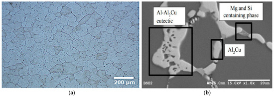
Figure 1.
(a) Optical and (b) SEM micrographs of B206 aluminum–copper casting alloy showing Al grains of matrix and Cu-rich intermetallics at grain boundaries.
3.2. Electrochemical Studies at Different Temperatures and DO Conditions
Figure 2 shows the polarization curves for the B206 alloy in naturally aerated and deaerated artificial seawater at 10 °C. The corrosion potential (Ecorr) value of B206 in the naturally aerated solution is higher than that in the deaerated solution; the difference is ca. 0.5 V. The change in the DO condition influences the cathodic process and subsequently, the corrosion potential. During potentiodynamic polarization, the pitting potential (Epit) is normally defined as the potential at which the anodic current increases significantly with further applied potential [21], as labeled in Figure 2. Epit corresponds to the potential at which pits will nucleate and grow. The onset of Epit provides an indication of the pitting resistance of a material in a specific environment and could be compared to the Epit of other materials in the same environment or of the same material in other environments. Figure 2 also shows that the anodic polarization curve of B206 presents an active–passive breakdown transition in the deaerated environment, while the corresponding curve in the naturally aerated environment indicates that localized corrosion of B206 can occur under open-circuit conditions. The change in cathodic reaction by introducing oxygen in the solution causes an increase in the Ecorr close to Epit.
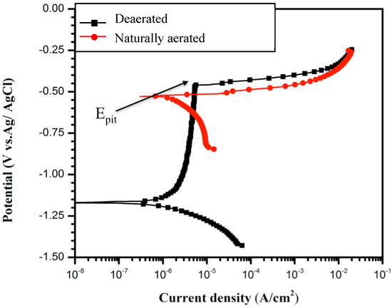
Figure 2.
Potentiodynamic polarization curves for B206 in artificial seawater solution at 10 °C showing the effect of aeration on passivity.
The effect of seawater temperature on the polarization curves of B206 was investigated in deaerated conditions. Figure 3 shows the polarization curves for the B206 alloy at temperatures ranging from 6 to 25 °C with deaerated artificial seawater. From Figure 3, it is evident that the temperature has a negligible effect on Epit. However, the passive current increases with increasing temperature in deaerated solution. It is also noted that the increase in passive current density appears more pronounced at lower temperatures. Whereas a clear separation of the passive region is observed between the 6 °C and 10 °C profiles, no significant difference is seen between the 14 °C and 25 °C profiles, even though the latter two profiles have a larger temperature difference than the former profile pair.
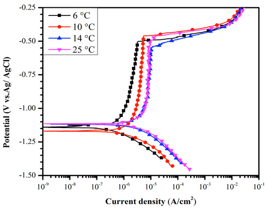
Figure 3.
Polarization curves for B206 in deaerated artificial seawater solution showing the effect of temperature (6, 10, 14, and 25 °C) on current density.
3.3. Passive Layer Behavior
3.3.1. Passive Current Density Decay
The current density decay transients measured during anodizing at −0.65 VAg/AgCl in deaerated artificial seawater are shown in Figure 4. The passive current density (ipass) increased with increasing temperature, which implies decreased passive layer protection and increased corrosion rate with increasing temperature.
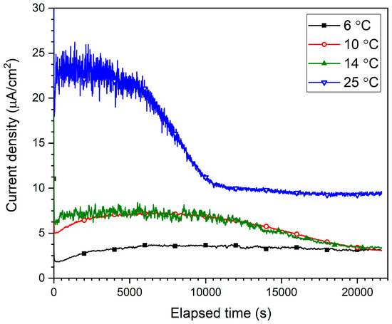
Figure 4.
Passive current density decay transients measured during the 6 h anodizing of B206 at −0.65 VAg/AgCl in deaerated seawater showing the effect of temperature (6, 10, 14, and 25 °C).
The smoothest and most uniform transient corresponds to the 6 °C solution, reaching a stable current density of approximately 3 µA/cm2 after around 6000 s of anodizing. The passive current density in the 10 °C solution reached a slightly higher current density, yet only stabilized towards the end of the 6 h anodizing period. This longer stabilization period also existed for the 14 °C transient, in addition to visibly more unsteadiness in the ipass measurement, especially towards the beginning of the anodizing process. This indicates instability of the passive layer formation, an occurrence which manifests itself the most in the 25 °C current density transients during the first 10,000 s of anodizing. Hence, not only do the final ipass values reached after 6 h of anodizing show the less robust passive layer(s) formed at higher temperatures, the instability in the transients during the earlier development stages allude to more difficult passive layer growth therein due to the increased dissolution rate of Al(OH)3 at higher temperatures counteracting its formation from Al2O3, as described in the next section.
3.3.2. Passive Layer Components and Structure
Aluminum oxide (Al2O3) forms immediately upon exposure of Al to atmospheric air containing O2. Through anodizing in the alkaline chloride-containing solution, the surface of the aluminum alloy becomes covered with a duplex structure consisting of an inner anhydrous Al2O3 layer adjacent to the substrate surface and an outer hydrous layer of aluminum hydroxide (Al(OH)3) corrosion product [26]. Both components of this dual-structure thicken with continued anodizing at the passive −0.65 VAg/AgCl potential in these alkaline solutions [27], leading to a decrease in the anodic dissolution of the Al-based substrate.
In deaerated conditions, the formation of Al(OH)3 corrosion product follows a three-step process involving intermediary Al(OH)2+ and Al(OH)2+ complexes as shown in Reactions (1) to (3) [27,28]. The corresponding cathodic reaction is the reduction of water, as shown in Reaction (4). The formation and continual thickening of the Al(OH)3 corrosion product increases the impedance of the overall dual-layer barrier, enhancing the corrosion protection of the aluminum alloy substrate.
Al + OH− ↔ Al(OH)2+ + 3e−
Al(OH)2+ + OH− ↔ Al(OH)2+
Al(OH)2+ + OH− ↔ Al(OH)3
2H2O + 2e− → 2OH− + H2
The stabilization of the ipass transients shown in Figure 4 can therefore be explained as the slow decay of the ratio between the formation and dissolution rate of Al(OH)3 to unity following a period where the formation rate exceeded the dissolution rate. However, since the ipass transients at all temperatures tested eventually reach stability, the differences in final ipass values for different temperatures cannot be explained by the formation vs. dissolution ratios. Rather, it is suggested here to be the result of structural (i.e., thickness and porosity) and electronic (i.e., semiconductive) differences in the duplex-layer as evidenced by the EIS and Mott–Schottky results below, respectively.
3.3.3. EIS
Figure 5 shows the Nyquist impedance representations of the EIS impedance spectra for anodized B206 specimens in deaerated seawater at temperatures between 6 and 25 °C. At the coldest temperature of 6 °C, it is seen that the Nyquist profile manifests as a nearly complete depressed semicircle, with the real component of the impedance (Zre) reaching a value slightly greater than 3 × 10⁴ Ω cm2 at the lowest frequency. Although the adsorption of Cl− on the surface of anodized Al specimens in Cl−-containing electrolytes is an established phenomenon [28,29,30], the Nyquist plot at 6 °C reveals the absence of significant auxiliary processes such as adsorption or induction at lower frequencies at this temperature.
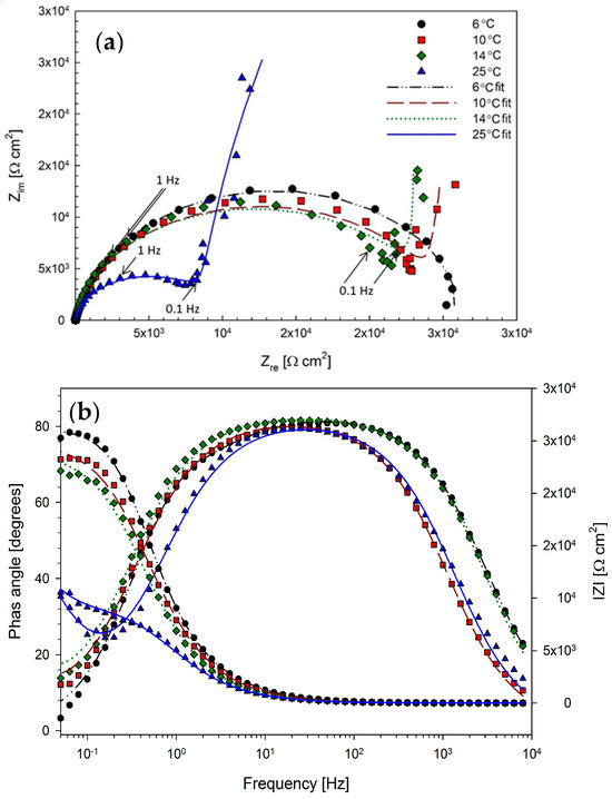
Figure 5.
(a) Nyquist plot with 0.1 and 1 Hz frequencies indicated, and (b) Bode plot representations of the EIS impedance spectra obtained at −0.65 VAg/AgCl for anodized B206 specimens in deaerated seawater, showing the effect of temperatures between 6 and 25 °C.
Based on the duplex structure of the passive layer known to form on Al in alkaline media [27,28], as described in the previous section, an electrical equivalent (EEC) with passive film/layer resistance and constant phase element (CPE), denoted as Rf and Qf, respectively, is proposed to model the EIS result at this temperature. This is shown in Figure 6 with a parallel charge-transfer resistance (Rct) and double-layer capacitance (Qdl) in series to model the solid-electrolyte interface at which electron transfer occurs. A schematic of the corresponding proposed physical system is also illustrated.
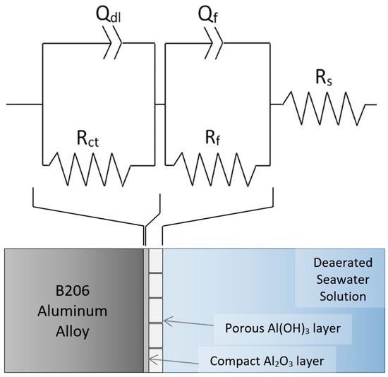
Figure 6.
Proposed EEC and physical occurrences for EIS at −0.65 VAg/AgCl on anodized B206 in deaerated seawater at 6 °C.
In the proposed EEC, CPEs were used instead of ideal capacitor elements due to expected surface heterogeneities in practice [31]. The fitting results of the EEC in Figure 6 for the 6 °C EIS spectrum are shown in Table 3 and are overlaid on Figure 5. The results show a good correlation between the EEC and the experimental measurements, as seen from a χ2 value of 4.22 × 10⁻⁴ and a maximum error in fit below 2.06%. It is noted that an EEC with a nested parallel adsorption segment (i.e., {R(Q(R(QR)))}) was attempted in modelling the 6 °C EIS spectrum, yet resulted in no significant fitting correlation difference compared to the EEC in Figure 6. However, when a simpler {R(QR)} as in [32] was attempted, a drop in fitting accuracy was observed. This indicates that a two-time-constant EEC best suits the EIS spectrum measured at 6 °C.
Table 3.
EIS component values for B206 anodized at −0.65 V vs. Ag/AgCl in seawater solution at 6, 10, 14, and 25 °C.
Figure 5 also shows the Nyquist plots for the EIS conducted at 10, 14, and 25 °C. In the Nyquist plots at these temperatures, much more noticeable supplemental electrochemical processes can be identified at low frequencies <0.1 Hz. This indicates a change in governing mechanism; based on the characteristic linear slope segments at low frequencies in the Nyquist representations, this is likely due to diffusion-controlled behavior [31].
It has been described earlier that a duplex passive layer structure exists on the anodized B206 specimens, where a compact inner anhydrous layer of Al2O3 resides between the alloy substrate and a porous outer hydrous Al(OH)3 layer. In Cl−-containing electrolytes, the adsorption of Cl− onto the outer Al(OH)3 layer has been an established account by other researchers [28,29]. In a recognized work by Nguyen and Foley [33], the reaction activation energy between Cl− and the intermediary Al(OH)2+ complex of Reaction (3) was shown to be lower than that between Cl− and Al3+. Hence, adsorbed Cl− on the outer layer of the passive film reacts preferentially with Al(OH)2+, ultimately thinning and breaking down the Al(OH)3 layer. The ensuing breakdown of the Al(OH)3 layer under the influence of Cl− results in AlCl4− through the multi-step process of Reactions (5) to (8) shown by McCafferty [34]:
Al(OH)3 + Cl− ↔ Al(OH)2Cl + OH−
Al(OH)2Cl + Cl− ↔ Al(OH)Cl2 + OH−
Al(OH)Cl2 + Cl− ↔ AlCl3 + OH−
AlCl3 + Cl− ↔ AlCl4−
In a fundamental investigation by Kolics et al. [35], it was demonstrated that this Cl−-induced adsorption on the Al passive layer is dependent on pH, where the Cl− concentration on the surface decreases with increasing pH. Although the pH of the electrolytes in the present work does not change substantially with temperature, an increase in temperature still increases the rate of Al(OH)3 dissolution into AlCl4− simply based on the temperature influence in the Arrhenius law. As such, even at a constant anodizing potential of −0.65 VAg/AgCl and a constant Cl− concentration in the anodizing solution, at increased temperatures the thinning and pitting of the outer Al(OH)3 ensues at a faster rate; this has been shown to drastically decrease the film resistance [28], increase pore sizes allowing the diffusion of electro-active species therein, and hence increase the corrosion rate of the Al alloy substrate.
Based on the manifestation of mass-transfer controlled behavior at 10, 14, and 25 °C in the EIS spectra of Figure 5, the EEC of Figure 7 is proposed for modelling electrochemical behavior at these temperatures. A corresponding schematic of the proposed physical occurrences is also shown in Figure 7. Here, the combined influence of increased temperature and aggressive Cl− ions in the alkaline solution is suggested to thin and pit the Al(OH)3 outer layer, creating larger channels for the diffusion of key electroactive species during the ensuing corrosion of the substrate. The Nyquist spectra at 10, 14, and 25 °C show near characteristic Warburg diffusion element (W) behavior [36]. The fitting results of the EEC in Figure 7 for the 10, 14, and 25 °C EIS spectra are shown in Table 3 and are overlaid on Figure 5. Again, the results show a good correlation between the EEC and the experimental measurements, with χ2 on the order of low 10−3 values and a maximum error in fit below 4.64%. Overall, steady decreases in Rct and Rf values with increased temperature demonstrate the increased corrosion caused by the decreased passive layer protectiveness at higher temperatures.
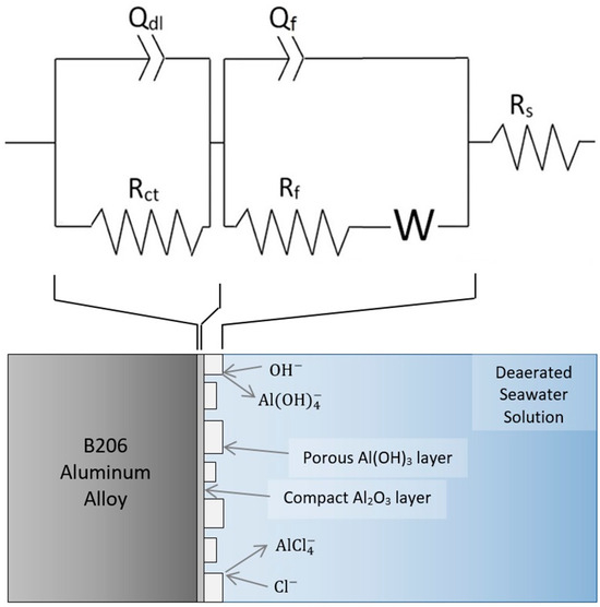
Figure 7.
Proposed EEC and physical occurrences for EIS at −0.65 VAg/AgCl on anodized B206 in deaerated seawater at 10, 14, and 25 °C.
3.3.4. Mott–Schottky Analysis and Passive Layer Thickness
The Mott–Schottky plots of anodized B206 in seawater solutions at 6, 10, 14, and 25 °C are shown in Figure 8. The Mott–Schottky technique relies on the assumption that at high applied frequencies, like the 1 kHz used in this work, the capacitance at the passive layer’s interface with the electrolyte mainly represents the space-charge layer capacitance (Csc) [37]. This is because Csc is considered to be much less than the capacitance of the Helmholtz layer. Therefore, the Csc−2 vs. potential representation of the Mott–Schottky plot in Figure 8 can be used to describe the semi-conductive behavior of the depletion region in the passive layer anodized on B206, at the four temperatures tested. Figure 8 shows increasing Csc with temperature and a linear relationship between the capacitance and the applied potential in the passive potential region investigated. The positive slopes (S) of the Mott–Schottky plot at every temperature tested indicate n-type semi-conductive behavior of the passive layer, agreeing with prior electrochemical studies on Al2O3 [38,39,40].
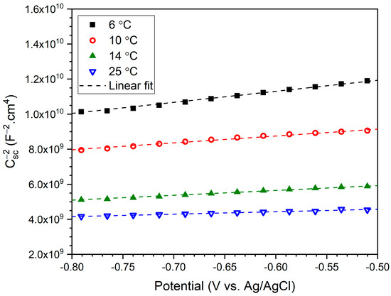
Figure 8.
Mott–Schottky plots at 1 kHz between −0.8 VAg/AgCl and −0.5 VAg/AgCl after 6 h of anodizing in deaerated seawater, showing the effect of 6, 10, 14, and 25 °C temperatures on Csc.
For an n-type semiconductor, the charge distribution as a function of applied potential can be determined through Equation (9), where Nd represents the donor density, Efb is the flat-band potential, k is the Boltzmann constant, T is the temperature in Kelvins, ε is the dielectric constant of the passive layer (ε ≈ 10 for Al alloys [41]), ε0 is the vacuum permittivity (8.85 × 10⁻¹⁴ F cm−1), and e is the elementary charge (1.6 × 10⁻¹⁹ C).
Thus, Nd for the passive layer anodized on B206 in deaerated seawater can be determined from the corresponding term or slope S in the experimental Csc−2 vs. the potential plot of Figure 8.
Using the linear fit slope values overlaid on the figure, Nd values are calculated and plotted in Figure 9. The Nd values are seen to increase with the temperature of the anodizing solution. These Nd values are comparable to densities on the order of 1021 cm−3 measured for the passive layers of other Al alloys in the literature [32,42]. Based on the point defect model [43], increased Nd indicates an increase in defects in the anodized passive layer with temperature. Considering the recognized attribution of n-type behavior to metal interstitials and oxygen vacancies in the oxide layer [29,42], the trend in Figure 9 specifically reveals an increased density of oxygen vacancies in the Al2O3 inner layer at higher temperatures. This increased oxygen vacancy density at higher temperature is directly correlated to increased conductivity and thus decreased protectiveness of the Al2O3 layer [44], agreeing with the trend of passive current densities in Figure 3 and Figure 4, and the decreased Rf with temperature shown in Table 3. Thus, it is shown here that increasing the temperature of the anodizing solution not only weakens the Al(OH)3 outer layer on B206, but also leads to a less resistive Al2O3 inner layer due to a more defective electronic structure containing a higher density of oxygen vacancies.
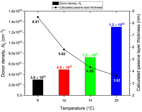
Figure 9.
Donor density and passive layer thickness values for B206 anodized for 6 h in deaerated seawater at temperatures between 6 and 25 °C, calculated from Mott–Schottky and EIS results, respectively.
The role of increased temperature in the reduction in the anodized film’s protection is further supported through the calculation of passive layer thickness. As overlaid on the Nd results of Figure 9, a decrease in the thickness of the passive layer with temperature was found through calculations using the Power-Law (P-L) model [45,46,47,48]. The model converts the CPE parameter for the passive layer (Qf in Figure 4) to an effective capacitance for the layer represented by Cf, through a relationship involving resistivity of the passive layer (ρ0), the dielectric constant of the layer (ε), the vacuum permittivity (ε0), and the exponent n describing the capacitive idealness of the CPE [48]:
The thickness of the anodized passive layer (df) on B206 after 6 h is then calculated through Equation (12), where A is the effective surface area of the specimen and the remaining ε, ε0, and Cf parameters are as previously described.
The calculation of df on B206 yields thickness values between approximately 3 and 9 nanometers (nm), as shown in Figure 9. These values are comparable to the thicknesses of air-formed Al2O3 layers on Al calculated through direct methods such as X-ray Photoelectron Spectroscopy (XPS) [29]. The air-formed oxide layer thicknesses on Al reported in the literature range from 2 nm [49] to approximately 5 nm [50]. The higher df results of the present work compared to the literature is attributed to two main reasons: (1) the added contribution of Al(OH)3 in the Qf values modeled from EIS, especially at 6 °C where it was shown the outer layer is more intact; and (2) the thickening of both the Al2O3 inner layer and the Al(OH)3 outer layer through the 6 h anodizing process. The decreasing trend of df with increasing temperature corroborates previously discussed results from Mott–Schottky, EIS, and polarization of both the potentiostatic and potentiodynamic type.
4. Conclusions
The properties and growth of passive multilayers on B206, anodized in deaerated artificial seawater at different temperatures, were studied using potentiodynamic polarization, EIS, current density decay, and Mott–Schottky analysis.
- Potentiodynamic polarization studies on B206 demonstrate that the effect of dissolved oxygen is more significant than that of temperature. The anodic polarization curves present an active–passive breakdown transition in deaerated seawater, whereas localized corrosion of B206 can occur under open-circuit conditions in aerated seawater.
- The protectiveness of the outer Al(OH)3 layer formed through anodizing B206 in deaerated seawater decreases with increased temperature in the 6–25 °C range. This is proposed to be due to the higher rate of Cl−-induced dissolution of the outer Al(OH)3 passive layer at higher temperatures, increasing the size and density of pores therein. Increased diffusion of electroactive species with temperature, seen in the EIS results, corroborates the inference that enhanced breakdown of Al(OH)3 at higher temperatures forms larger-sized pores reaching through to the Al2O3 inner layer.
- Increasing the temperature of the deaerated seawater during anodizing not only affects the pore size and density in the outer Al(OH)3 passive layer but also degrades the resistivity of the inner Al2O3 layer. Through Mott–Schottky analysis, the donor density (mainly oxygen vacancies) of the Al2O3 inner layer decreases with increased temperature, strongly contributing to the reduced protectiveness of the overall duplex-structure passive layer on B206. Donor densities of the passive layer exhibiting n-type semiconductive behavior are on the order of 1021 cm−3, comparing well with values for other Al alloys reported in the literature.
- Passive layer thickness is found to be between 3 and 9 nm using the Power-Law model, comparable to those of Al-oxide layers calculated through other characterization methods in the literature. A temperature-dependent trend for passive layer thickness supports decreased protectiveness (due to thinning) at the higher temperatures in the 6–25 °C range. Mainly, this is attributed to the more difficult growth of the outer passive layer at higher temperatures due to temperature-induced increased dissolution rate of Al(OH)3 counteracting its formation from Al2O3.
Author Contributions
Conceptualization, I.M.G., S.P. and E.A.; methodology, I.M.G. and S.P.; validation, I.M.G., S.P. and E.A.; formal analysis, I.M.G. and S.P.; investigation, I.M.G. and S.P.; data curation, I.M.G., S.P. and D.N.; writing-original draft preparation, I.M.G. and S.P.; writing-review and editing, D.N., A.A., D.M.M. and E.A.; supervision, A.A., D.M.M. and E.A.; project administration, A.A., D.M.M. and E.A.; funding acquisition, A.A., D.M.M. and E.A. All authors have read and agreed to the published version of the manuscript.
Funding
The authors gratefully acknowledge financial support from the Natural Sciences and Engineering Research Council of Canada (NSERC).
Data Availability Statement
The raw data supporting the conclusions of this article will be made available by the authors on request.
Conflicts of Interest
The authors declare no conflicts of interest.
References
- Lorenzi, S.; Carrozza, A.; Cabrini, M.; Nani, L.; Andreatta, F.; Virtanen, E.; Tirelli, T.; Pastore, T. Corrosion behavior assessment of an Al-Cu alloy manufactured via laser powder bed fusion. Corros. Sci. 2024, 227, 111698. [Google Scholar] [CrossRef]
- Chiu, W.-T.; Akama, T.; Tahara, M.; Inamura, T.; Nakamura, K.; Hosoda, H. Aging behaviors of the Al–Cu alloy via ultrasound-promoted thermal treatments. J. Mater. Res. Technol. 2024, 28, 478–489. [Google Scholar] [CrossRef]
- Ren, L.; Tan, R.; Zhang, D.; Zhang, X. Regulating grain boundary element distribution of Al-Cu alloy to improve corrosion resistance by boron addition. Corros. Sci. 2025, 244, 112665. [Google Scholar] [CrossRef]
- Alhejazi, H.J.; Maijer, D.M.; Avraham, S.; Phillion, A.B. Numerical-Experimental Assessment of the Semi-Solid Contraction Behavior of Grain-Refined High Strength Aluminum Alloy, B206. Metall. Mater. Trans. A 2024, 55, 3164–3171. [Google Scholar] [CrossRef]
- Manivannan, M.; Sokolowski, J.H.; Northwood, D.O. An Investigation of the Effect of Various Heat Treatments on the Corrosion Resistance of a High-Strength Aluminum-Copper Casting Alloy. In Proceedings of the 48th Annual Conference of the Australasian Corrosion Association 2008: Corrosion and Prevention 2008, Wellington, New Zealand, 16–19 November 2008; pp. 1–10. [Google Scholar]
- Kearney, A.L.; Rooy, E.L. ASM Handbook Volume 02—Properties and Selection: Nonferrous Alloys and Special-Purpose Materials, 10th ed.; ASM International: Materials Park, OH, USA, 1990. [Google Scholar]
- Pournazari, S.; Maijer, D.M.; Asselin, E. Effects of Dissolved Oxygen and Temperature on the Corrosion Properties of B206 and A356 Aluminum Alloys Exposed to Seawater. In Proceedings of the Corrosion Conference and Expo, Vancouver, BC, Canada, 6–10 March 2016; p. NACE-2016-7561. [Google Scholar]
- Davis, J.; Destefani, J.; Frissell, H. ASM Metals Handbook Volume 13 Corrosion; ASM International: Materials Park, OH, USA, 1987. [Google Scholar]
- Arima, H. Seawater Corrosion of the Anodized A1050 Aluminum Plate for Heat Exchangers. Metals 2025, 15, 300. [Google Scholar] [CrossRef]
- Pournazari, S.; Maijer, D.; Asselin, E. FIB/SEM study of pitting and intergranular corrosion in an Al-Cu alloy. Corrosion 2017, 73, 927–941. [Google Scholar] [CrossRef] [PubMed]
- Rakhmonov, J.U.; Qi, J.; Bahl, S.; Dunand, D.C.; Shyam, A. Co-, Ni- and Fe-rich grain-boundary phases enhance creep resistance in θ′-strengthened Al-Cu alloys. Mater. Sci. Eng. A 2024, 913, 147052. [Google Scholar] [CrossRef]
- Zhu, Y.; Frankel, G.S.; Miller, L.G.; Garves, J.; Pope, J.; Locke, J. Electrochemical Characteristics of Intermetallic Phases in Al–Cu–Li Alloys. J. Electrochem. Soc. 2023, 170, 021502. [Google Scholar] [CrossRef]
- Yoshida, H.; Nishimoto, M.; Muto, I.; Takaya, M.; Kyo, Y.; Minoda, T.; Sugawara, Y. Difference in the Precursory Process of the Intergranular Corrosion of Aged Al-Cu and Al-Cu-Mg Alloys in 0.1 M NaCl. J. Electrochem. Soc. 2023, 170, 111501. [Google Scholar] [CrossRef]
- de Sousa Araujo, J.V.; Costa, I.; Zhou, X. Comparison of Constituent Intermetallic Particles in Different Aluminium Alloys. Metallogr. Microstruct. Anal. 2025, 14, 106–119. [Google Scholar] [CrossRef]
- Kayani, S.H.; Ha, H.-Y.; Kim, B.-J.; Cho, Y.-H.; Son, H.-W.; Lee, J.-M. Impact of intermetallic phases on the localised pitting corrosion and high-temperature tensile strength of Al–SiMgCuNi alloys. Corros. Sci. 2024, 233, 112064. [Google Scholar] [CrossRef]
- Kosari; Tichelaar, F.; Visser, P.; Zandbergen, H.; Terryn, H.; Mol, J.M.C. Dealloying-driven local corrosion by intermetallic constituent particles and dispersoids in aerospace aluminium alloys. Corros. Sci. 2020, 177, 108947. [Google Scholar] [CrossRef]
- Miramontes, J.C.; Tiburcio, C.G.; Mata, E.G.; Alcála, M.Á.E.; Maldonado-Bandala, E.; Lara-Banda, M.; Nieves-Mendoza, D.; Olguín-Coca, J.; Zambrano-Robledo, P.; López-León, L.D.; et al. Corrosion Resistance of Aluminum Alloy AA2024 with Hard Anodizing in Sulfuric Acid-Free Solution. Materials 2022, 15, 6401. [Google Scholar] [CrossRef]
- de S. Araujo, J.V.; Chen, J.; Costa, I.; Zhou, X. Localized corrosion in anodized aluminium alloys: The role of constituent particle-induced defects in anodic films. Corros. Sci. 2025, 252, 112961. [Google Scholar] [CrossRef]
- ASTM E3061; Standard Test Method for Analysis of Aluminum and Aluminum Alloys by Inductively Coupled Plasma Atomic Emission Spectrometry. ASTM International: West Conshohocken, PA, USA, 2024. Available online: https://store.astm.org/e3061-17.html (accessed on 1 May 2017).
- ASTM D1141; Practice for the Preparation of Substitute Ocean Water. ASTM International: West Conshohocken, PA, USA, 2021. Available online: https://store.astm.org/d1141-98r21.html (accessed on 1 May 2017).
- Stansbury, E.E.; Buhcanan, R. Fundamentals of Electrochemical Corrosion; ASM International: Materials Park, OH, USA, 2000. [Google Scholar]
- Bok, F.; Moog, H.C.; Brendler, V. The solubility of oxygen in water and saline solutions. Front. Nucl. Eng. 2023, 2, 1158109. Available online: https://www.frontiersin.org/journals/nuclear-engineering/articles/10.3389/fnuen.2023.1158109 (accessed on 1 May 2017). [CrossRef]
- Kelly, R.G.; Scully, J.R.; Shoesmith, D.W.; Buchheit, R.G. Electrochemical Techniques in Corrosion Science and Engineering; CRC Press: Boca Raton, FL, USA, 2003. [Google Scholar] [CrossRef]
- Orazem, M.E. Measurement model for analysis of electrochemical impedance data. J. Solid State Electrochem. 2024, 28, 1273–1289. [Google Scholar] [CrossRef]
- Peltier, F.; Thierry, D. Localised corrosion of intermetallic particles on aluminium AA2099-T8. Corros. Eng. Sci. Technol. 2021, 56, 610–617. [Google Scholar] [CrossRef]
- Visser, P.; Gonzalez-Garcia, Y.; Mol, J.M.C.; Terryn, H. Mechanism of Passive Layer Formation on AA2024-T3 from Alkaline Lithium Carbonate Solutions in the Presence of Sodium Chloride. J. Electrochem. Soc. 2018, 165, C60–C70. [Google Scholar] [CrossRef]
- Ishii, K.; Ozaki, R.; Kaneko, K.; Fukushima, H.; Masuda, M. Continuous monitoring of aluminum corrosion process in deaerated water. Corros. Sci. 2007, 49, 2581–2601. [Google Scholar] [CrossRef]
- Lee, H.-J.; Park, I.-J.; Choi, S.-R.; Kim, J.-G. Effect of Chloride on Anodic Dissolution of Aluminum in 4 M NaOH Solution for Aluminum-Air Battery. J. Electrochem. Soc. 2017, 164, A549–A554. [Google Scholar] [CrossRef]
- Zhou, W.; Xue, F.; Li, M. Corrosion Behavior of Al-Mg Alloys with Different Alloying Element Contents in 3.5% NaCl Solution. Metals 2025, 15, 327. [Google Scholar] [CrossRef]
- Liang, Y.; Du, Y.; Zhu, Z.; Chen, L.; Liu, Y.; Zhang, L.; Qiao, L. Investigation on AC corrosion of aluminum alloy sacrificial anode in the artificial simulated seawater environment. Electrochim. Acta 2023, 446, 142002. [Google Scholar] [CrossRef]
- Vivier, V.; Orazem, M.E. Impedance Analysis of Electrochemical Systems. Chem. Rev. 2022, 122, 11131–11168. [Google Scholar] [CrossRef] [PubMed]
- Liu, Z.; Wang, J.; Qin, Z.; Xia, D.-H.; Behnamian, Y.; Hu, W.; Tribollet, B. A mechanistic study on stress corrosion cracking of sensitized AA5083 in a simulated water level fluctuation zone: Combined impedance analysis and tensile tests. Corros. Sci. 2025, 245, 112701. [Google Scholar] [CrossRef]
- Nguyen, T.H.; Foley, R.T. The Chemical Nature of Aluminum Corrosion II. The Initial Dissolution Step. J. Electrochem. Soc. 1982, 129, 27–32. [Google Scholar] [CrossRef]
- McCafferty, E. Sequence of steps in the pitting of aluminum by chloride ions. Corros. Sci. 2003, 45, 1421–1438. [Google Scholar] [CrossRef]
- Kolics, A.; Polkinghorne, J.C.; Wieckowski, A. Adsorption of sulfate and chloride ions on aluminum. Electrochim. Acta 1998, 43, 2605–2618. [Google Scholar] [CrossRef]
- Orazem, M.E.; Ulgut, B. On the Proper Use of a Warburg Impedance. J. Electrochem. Soc. 2024, 171, 40526. [Google Scholar] [CrossRef]
- Ning, Z.; Wen, D.; Zhou, Q.; Li, N.; Macdonald, D.D. Theoretical explanation of passivation behavior in OFP-Cu and OF-Cu. Acta Mater. 2024, 271, 119882. [Google Scholar] [CrossRef]
- Kumar, A.; Chaudhari, G.P. Passivity breakdown of high-strength 7068 aluminum alloy in borate buffer solutions containing chlorides. J. Solid State Electrochem. 2024, 28, 4087–4103. [Google Scholar] [CrossRef]
- Hu, X.; Gao, K.; Xiong, X.; Huang, H.; Wu, X.; Wen, S.; Wei, W.; Nie, Z.; Zhou, D. Influence of Grain Size and Film Formation Potential on the Diffusivity of Point Defects in the Passive Film of Pure Aluminum in NaCl Solution. Metals 2024, 14, 782. [Google Scholar] [CrossRef]
- Fernandes, J.C.S.; Picciochi, R.; Da Cunha Belo, M.; Silva, T.M.E.; Ferreira, M.G.S.; Fonseca, I.T.E. Capacitance and photoelectrochemical studies for the assessment of anodic oxide films on aluminium. Electrochim. Acta 2004, 49, 4701–4707. [Google Scholar] [CrossRef]
- Liu, Y.; Meng, G.Z.; Cheng, Y.F. Electronic structure and pitting behavior of 3003 aluminum alloy passivated under various conditions. Electrochim. Acta 2009, 54, 4155–4163. [Google Scholar] [CrossRef]
- Lv, J.; Luo, H. Effect of surface burnishing on texture and corrosion behavior of 2024 aluminum alloy. Surf. Coat. Technol. 2013, 235, 513–520. [Google Scholar] [CrossRef]
- Macdonald, D.D. On the Existence of Our Metals-Based Civilization I. Phase-Space Analysis. J. Electrochem. Soc. 2006, 153, B213–B224. [Google Scholar] [CrossRef]
- Zhang, J.; Zhang, W.; Yan, C.; Du, K.; Wang, F. Corrosion behaviors of Zn/Al–Mn alloy composite coatings deposited on magnesium alloy AZ31B (Mg–Al–Zn). Electrochim. Acta 2009, 55, 560–571. [Google Scholar] [CrossRef]
- Pan, C.; Behnamian, Y.; Guo, Y.; Qin, Z.; Hu, W.; Xia, D.-H.; Tribollet, B. Cavitation erosion of the AA7050 aluminum alloy in 3.5 wt% NaCl solution—Part 2: An impedance investigation of the effect of cavitation intensity on interfacial states. Corros. Sci. 2025, 251, 112936. [Google Scholar] [CrossRef]
- Ter-Ovanessian, B.; Galipaud, J.; Marcelin, S.; Tribollet, B.; Normand, B. Dielectric bi-layer model for electrochemical impedance spectroscopy characterisation of oxide film. Electrochim. Acta 2024, 492, 144307. [Google Scholar] [CrossRef]
- Nkoua, C.; Esvan, J.; Tribollet, B.; Basseguy, R.; Blanc, C. Combined electrochemical impedance spectroscopy and X-ray photoelectron spectroscopy analysis of the passive films formed on 5083 aluminium alloy. Corros. Sci. 2023, 221, 111337. [Google Scholar] [CrossRef]
- Mohammadi, M.; Choudhary, L.; Gadala, I.M.; Alfantazi, A. Electrochemical and Passive Layer Characterizations of 304L, 316L, and Duplex 2205 Stainless Steels in Thiosulfate Gold Leaching Solutions. J. Electrochem. Soc. 2016, 163, C883–C894. [Google Scholar] [CrossRef]
- Chang, C.-L.; Engelhard, M.H.; Ramanathan, S. Superior nanoscale passive oxide layers synthesized under photon irradiation for environmental protection. Appl. Phys. Lett. 2008, 92, 263103. [Google Scholar] [CrossRef]
- Strohmeier, B. An Esca Method for Determining the Oxide Thickness on Aluminum-Alloys. Surf. Interface Anal. 1990, 15, 51–56. [Google Scholar] [CrossRef]
Disclaimer/Publisher’s Note: The statements, opinions and data contained in all publications are solely those of the individual author(s) and contributor(s) and not of MDPI and/or the editor(s). MDPI and/or the editor(s) disclaim responsibility for any injury to people or property resulting from any ideas, methods, instructions or products referred to in the content. |
© 2025 by the authors. Licensee MDPI, Basel, Switzerland. This article is an open access article distributed under the terms and conditions of the Creative Commons Attribution (CC BY) license (https://creativecommons.org/licenses/by/4.0/).