
Microstructure and Mechanical Properties of Shoulder-Assisted Heating Friction Plug Welding 6082-T6 Aluminum Alloy Using a Concave Backing Hole

Abstract
1. Introduction
2. Materials and Methods
2.1. Materials
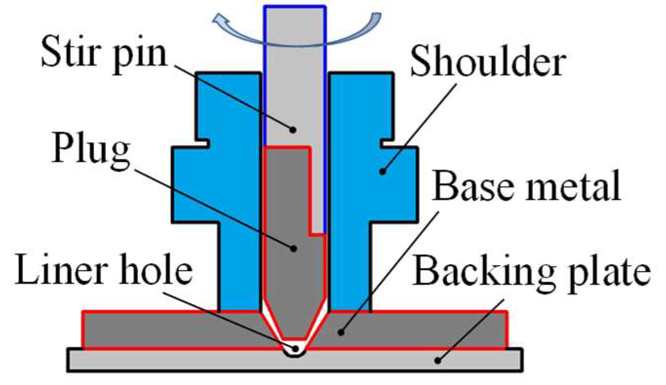
2.2. Methods
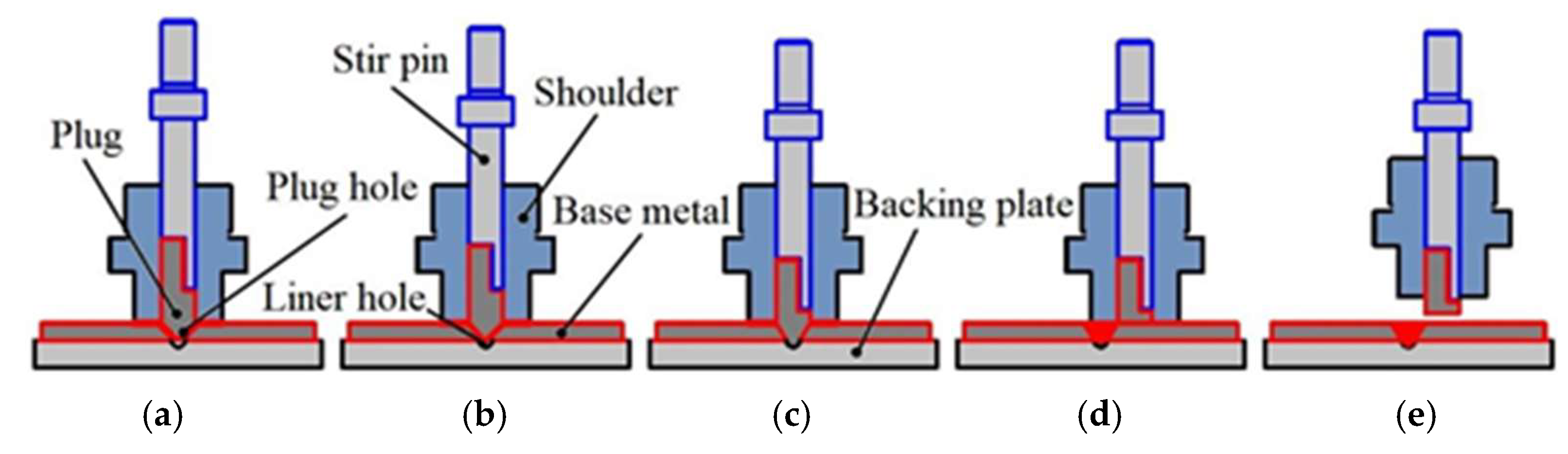
- (a)
- Initially, friction between the rotating shoulder and the base metal generates heat at the faying surfaces. This heat conducts into the workpiece, preheating the plug hole surface. The plug rotational speed matches that of the FPW process, with an auxiliary heating time of 65 s.
- (b)
- Upon completing preheating, the rotating plug advances axially into the plug hole. Contact under feed force initiates friction at the plug–plug hole interface. Continued axial feeding generates viscoplastic material that flows to fill the plug hole, constrained by the tool shoulder, the concave backing hole, and surrounding base metal.
- (c)
- When flash extrudes from the shoulder periphery, axial feeding terminates. Simultaneously, the shoulder retracts axially until its lower face aligns coplanar with the base metal upper surface, while sustained rotational contact maintains friction for continued heating. A rapid plug plunge then applies upsetting force (5 KN) to consolidate the nascent weld.
- (d)
- Post-upsetting, the rotating shoulder traverses horizontally across the base metal at 3 mm/s. The distance at which the remaining plug is sheared off during lateral movement is 5 mm. Shear forces at the shoulder–base metal interface sever the excess plug, forming a flush joint surface.
- (e)
- Finally, the shoulder fully retracts from the workpiece, and the severed plug remnant retained in the tool holder is ejected.
3. Experimental Results and Analysis
3.1. Macroscopic Morphology of Joints
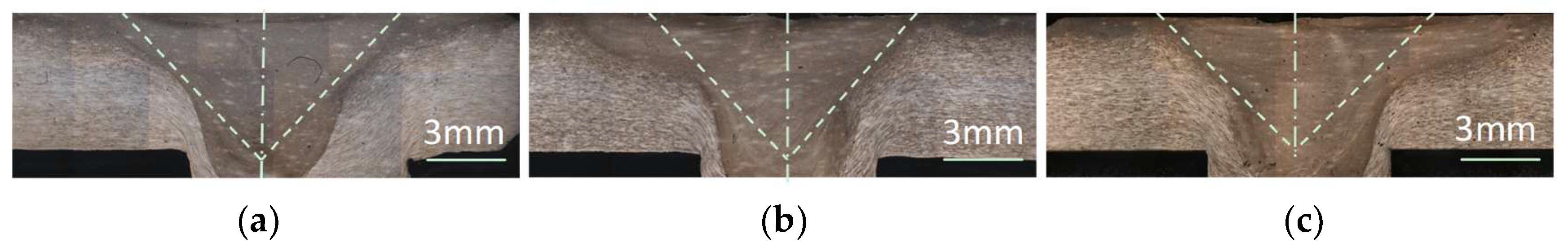
3.2. Cross-Sectional Morphology of Joints
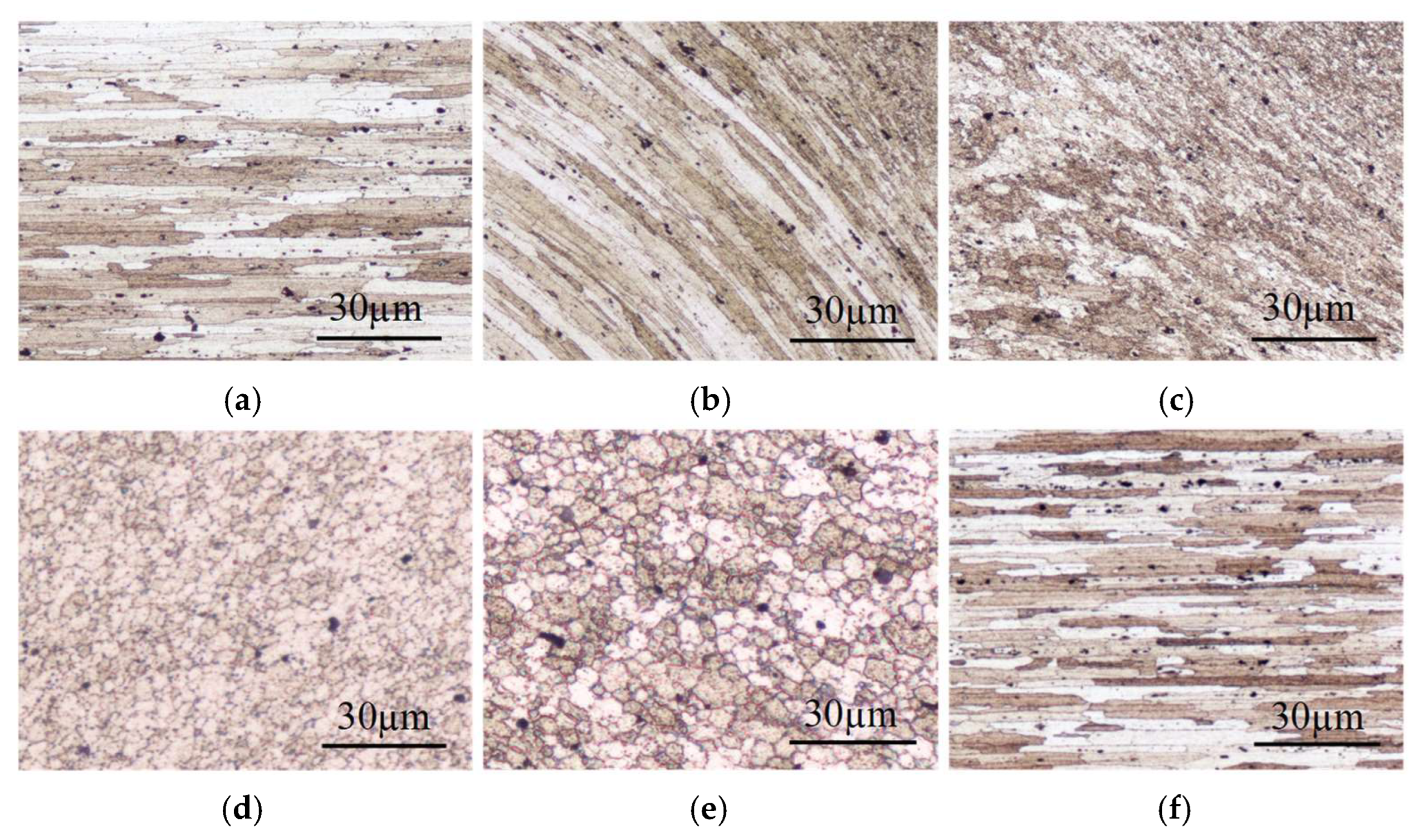
3.3. Microstructure of Joints
3.4. Mechanical Properties of Joints
3.5. Fracture Characteristics of Joints
4. Discussion
4.1. Effect of Concave Backing Hole Process on Microstructure of Joints
4.2. Effect of Concave Backing Hole Process on Mechanical Properties of Joints
4.3. Mechanism of Concave Backing Hole Process Influencing Joint Formation
5. Conclusions
- (1)
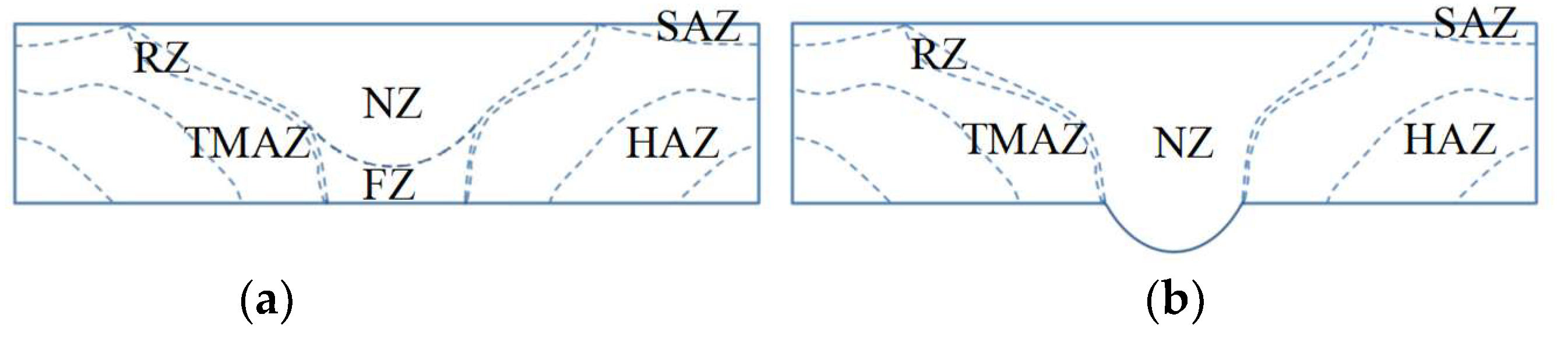
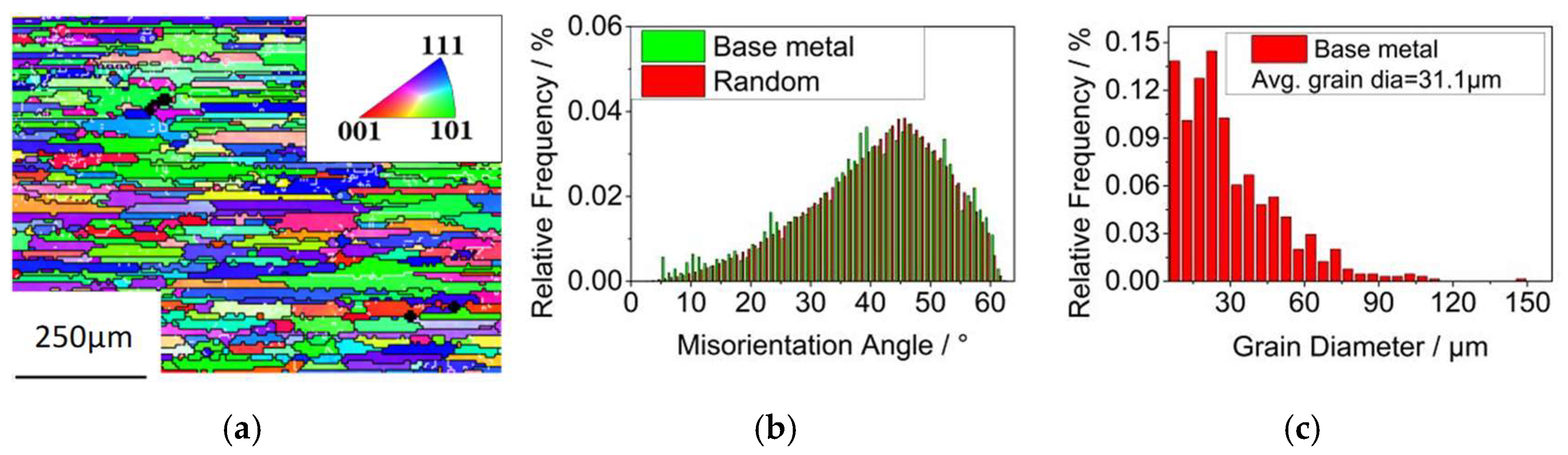
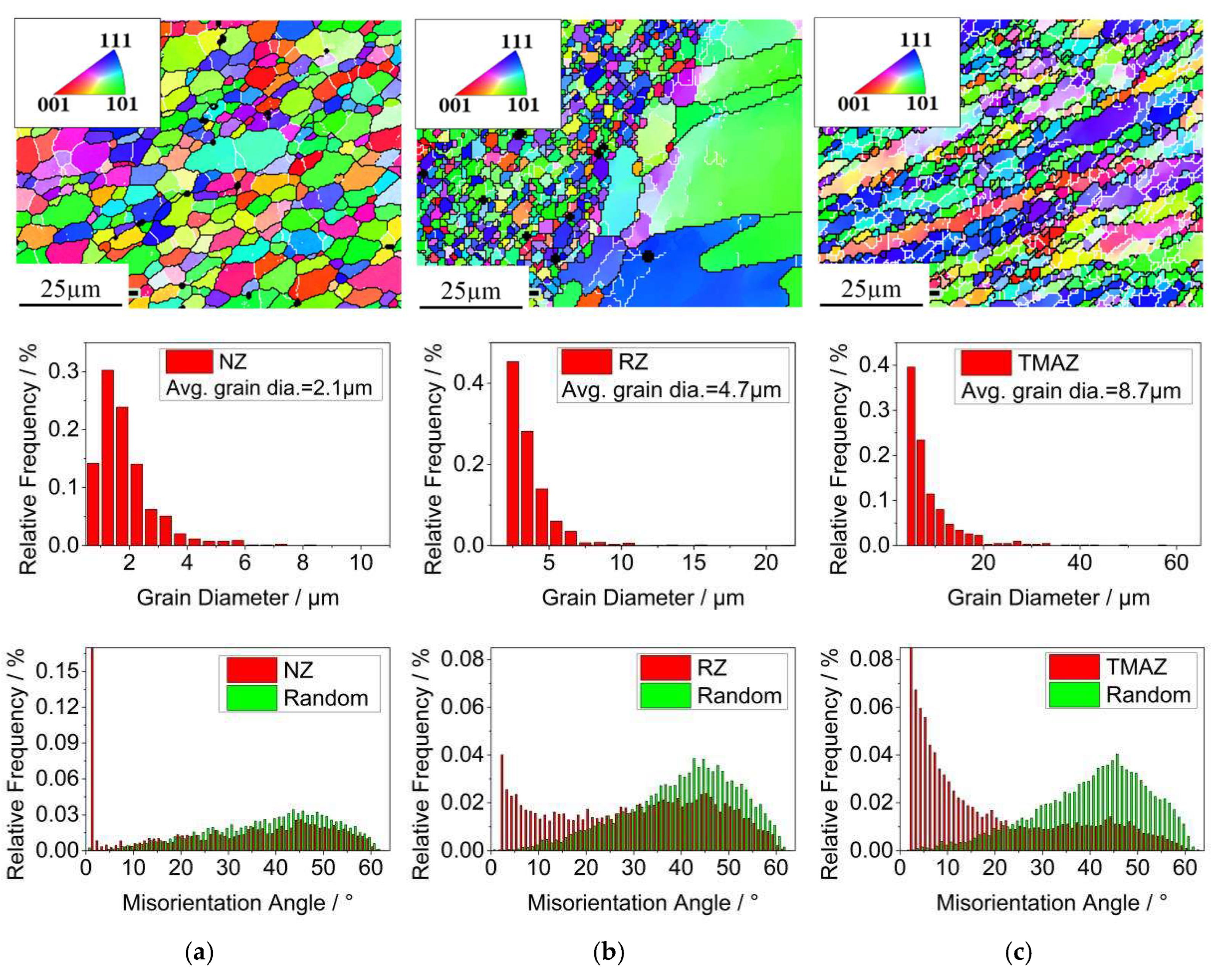
- The concave backing hole technique influenced the flow of plasticized material during shoulder-assisted heating FPW, thereby affecting the formation and characteristics of the joint’s microstructural zones. The resulting microstructure and its distribution across the joint were heterogeneous. Specifically, the NZ and SAZ consisted of fine, equiaxed grains, while the RZ served as a transition region. The TMAZ exhibited significant grain deformation (bending), and the HAZ retained the lath-like microstructure characteristic of the base metal.
- (2)
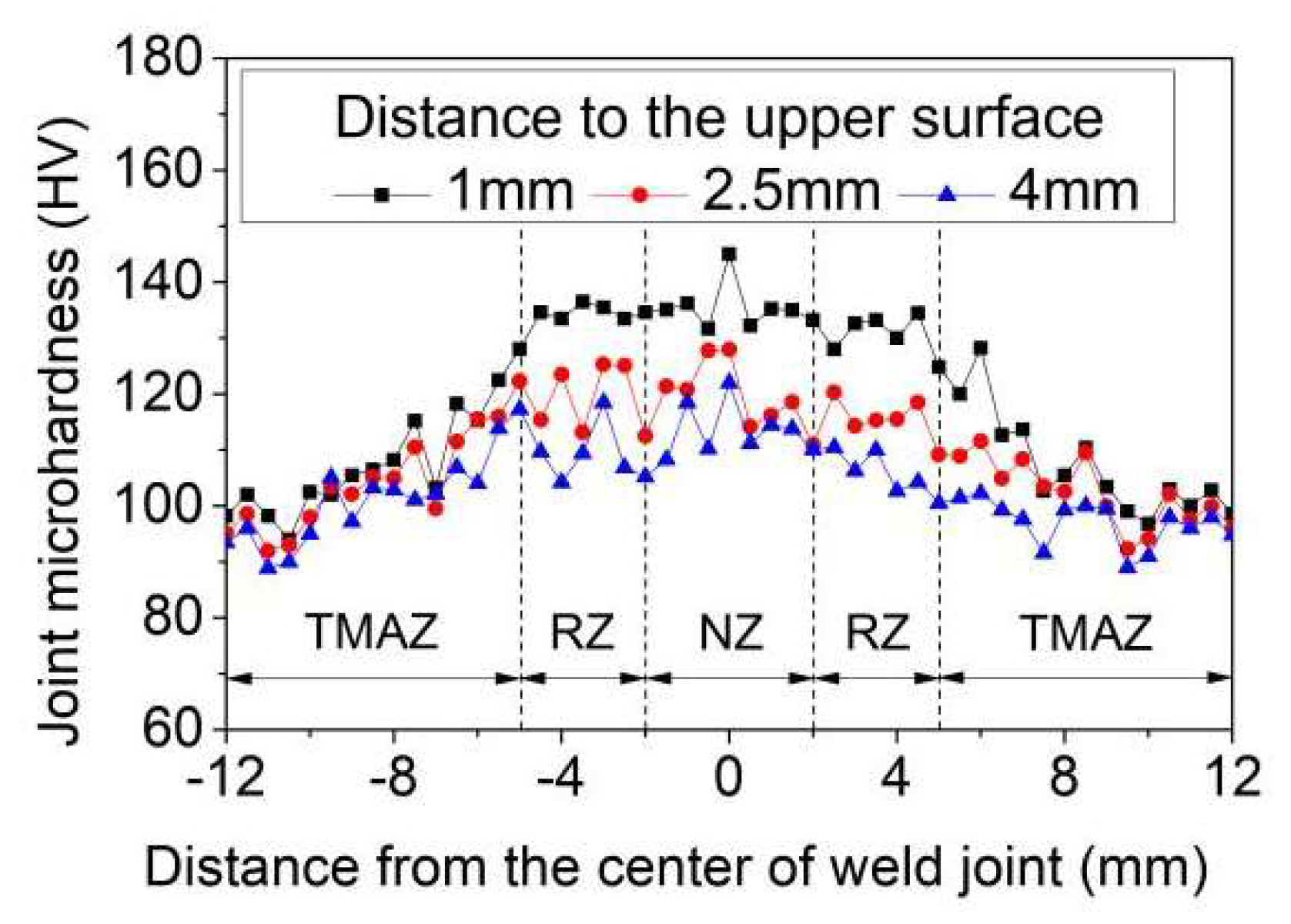
- The concave backing hole technique accelerated the flow of plasticized material during welding, promoting the formation of a more consolidated and refined microstructure and enhancing the overall mechanical performance of the joint. With the exception of a slight reduction in microhardness within the HAZ, hardness values in other regions of the joint exceeded that of the base metal. Hardness exhibited heterogeneity through the thickness, generally decreasing with increasing distance from the upper surface at a given vertical position.
- (3)
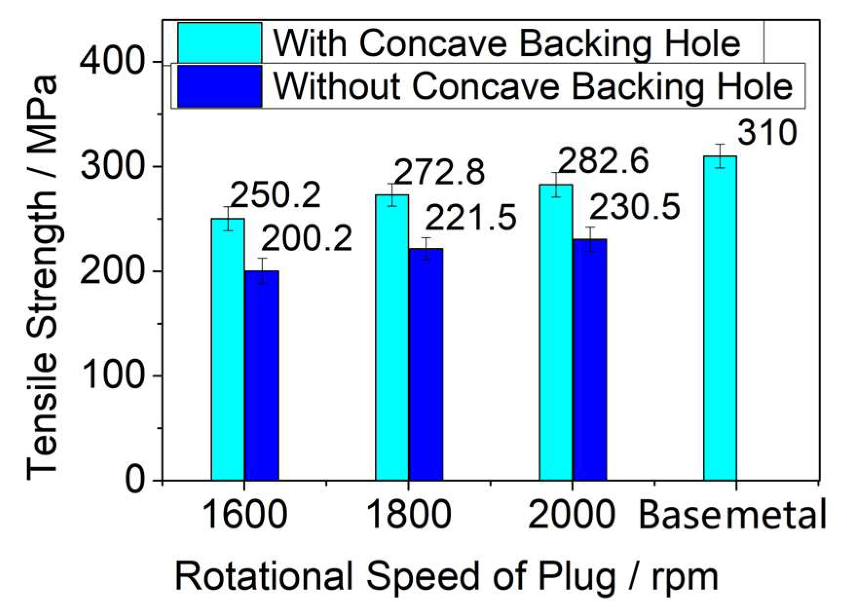
- Employing the concave backing hole technique eliminated the FZ expanded the extent of the NZ and improved the microstructural homogeneity within the weld. By eradicating weak bonding defects at the joint root, this approach increased the ultimate tensile strength to 278.10 MPa (equivalent to 89.71% of the base metal strength) and the elongation at fracture to 9.02%.
- (4)
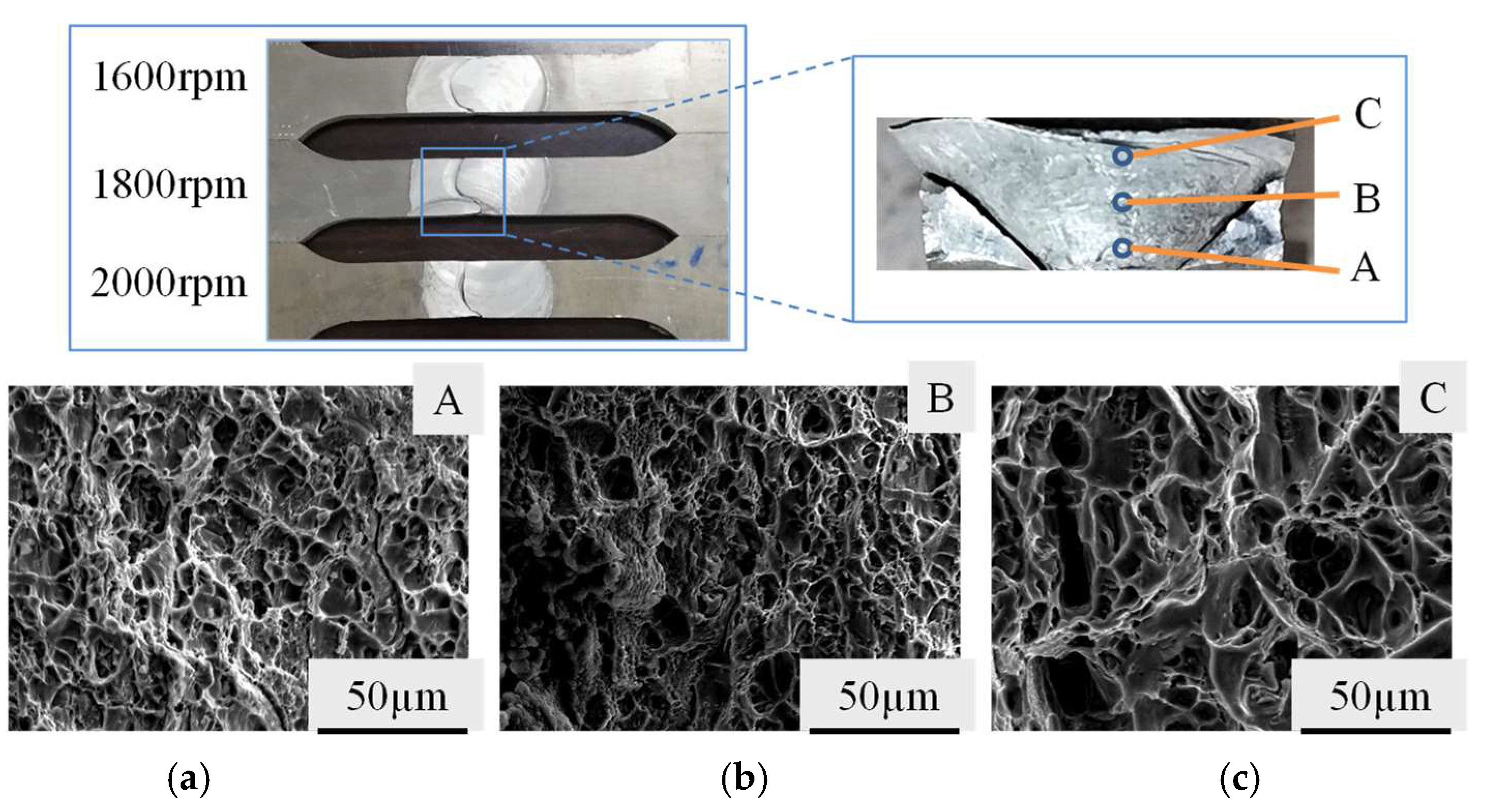
- The misorientation angle distributions between adjacent grains in the NZ, RZ, and TMAZ all deviated from a random distribution, indicating the occurrence of dynamic recrystallization (DRX). The NZ possessed the highest fraction of high-angle grain boundaries (HAGBs) compared to the RZ and TMAZ. The NZ consisted of fine, equiaxed grains with the smallest average grain size (2.1 µm), whereas the TMAZ exhibited the largest grain size (8.7 µm) among these zones. The interplay between temperature and deformation during the plug welding process governed the resulting grain morphology and its distribution across the different joint regions.
Author Contributions
Funding
Data Availability Statement
Conflicts of Interest
References
- Habba, M.I.A.; Ahmed, M.M.Z. Friction stir welding of dissimilar aluminum and copper alloys: A review of strategies for enhancing joint quality. J. Adv. Join. Process. 2025, 11, 100293. [Google Scholar] [CrossRef]
- Li, M.; Zhan, R.; Ji, X.; Zhang, K.Y.; Guan, W.; Huang, Y.M.; Cui, L. Prediction of mechanical properties for 2219 aluminum alloy friction stir weld joints based on force signals. Int. J. Adv. Manuf. Technol. 2025, 137, 3–4. [Google Scholar] [CrossRef]
- Teimurnezhad, J.; Pashazadeh, H.; Masumi, A. Effect of shoulder plunge depth on the weld morphology, macrograph and microstructure of copper FSW joints. J. Manuf. Process. 2016, 9, 254–259. [Google Scholar] [CrossRef]
- Khan, N.Z.; Siddiquee, A.N.; Khan, Z.A.; Shihab, S.K. Investigations on tunneling and kissing bond defects in FSW joints for dissimilar aluminum alloys. J. Alloys Compd. 2015, 648, 360–367. [Google Scholar] [CrossRef]
- Zheng, Q.X.; Feng, X.M.; Shen, Y.F.; Huang, G.Q.; Zhao, P.C. Effect of plunge depth on microstructure and mechanical properties of FSW lap joint between aluminum alloy and nickel-base alloy. J. Alloys Compd. 2017, 695, 952–961. [Google Scholar] [CrossRef]
- Zhou, N.; Song, D.F.; Qi, W.J.; Li, X.H.; Zou, J.; Attallah, M.M. Influence of the kissing bond on the mechanical properties and fracture behaviour of AA5083-H112 friction stir welds. Mater. Sci. Eng. A 2018, 719, 12–20. [Google Scholar] [CrossRef]
- Han, B.; Huang, Y.X.; Lv, S.X.; Wan, L.; Feng, J.C.; Fu, G.S. AA7075 bit for repairing AA2219 keyhole by filling friction stir welding. Mater. Des. 2013, 51, 25–33. [Google Scholar] [CrossRef]
- Du, B.; Yang, X.Q.; Tang, W.S.; Sun, Z.P. Numerical analyses of material flows and thermal processes during friction plug welding for AA2219 aluminum alloy. J. Mater. Process. Technol. 2020, 278, 116466. [Google Scholar] [CrossRef]
- Cui, L.; Yang, X.Q.; Wang, D.P.; Cao, J.; Xu, W. Experimental study of friction taper plug welding for low alloy structure steel: Welding process, defects, microstructures and mechanical properties. Mater. Des. 2014, 62, 271–281. [Google Scholar] [CrossRef]
- Huang, Y.X.; Han, B.; Lv, S.X.; Feng, J.C.; Leng, J.S.; Chen, X.B. Keyhole repair technique in filling friction stir welding based on solid-state bonding principle. Trans. China Weld. Inst. 2012, 33, 5–8. [Google Scholar]
- Huang, R.F.; Ji, S.D.; Meng, X.C.; Li, Z.W. Drilling-filling friction stir repairing of AZ31B magnesium alloy. J. Mater. Process. Technol. 2018, 255, 765–772. [Google Scholar] [CrossRef]
- Shen, Z.; Li, W.Y.; Ding, Y.; Hou, W.; Liu, X.C.; Guo, W.; Chen, H.Y.; Liu, X.; Yang, J.; Gerlich, A.P. Material flow during refill friction stir spot welded dissimilar Al alloys using a grooved tool. J. Manuf. Process. 2020, 49, 260–270. [Google Scholar] [CrossRef]
- Wang, G.Q.; Zhao, G.; Hao, Y.F.; Chen, X.F.; Zhao, Y.H. Repair technology for keyhole defects in friction stir welds of 2219 aluminum alloy. Aerosp. Mater. Technol. 2012, 42, 24–28. [Google Scholar]
- Hao, Y.F.; Bai, J.B.; Tian, B.; Gao, P.T.; Zhao, Y.H.; Ma, J.B. Microstructure and properties of joints repaired by fusion welding and FSW for keyhole defects in friction stir welds of 2219 aluminum alloy. Aeronaut. Manuf. Technol. 2014, 454, 83–87. [Google Scholar]
- Huang, Y.X.; Xie, Y.M.; Meng, X.C. A Continuous Feed Friction Stir Additive Manufacturing Device and Method. Chinese Patent CN113172331B, 22 April 2022. [Google Scholar]
- Cui, L.; Zhong, H.; Guan, W. A Continuous Extrusion Coaxial Feed Friction Stir Additive Manufacturing Process and Device. Chinese Patent CN116140783A, 23 May 2023. [Google Scholar]
- Tang, W.S.; Yang, X.Q.; Tian, C.B.; Xu, Y.S. Effect of process parameters on microstructure and properties of aluminum alloy friction extrusion additive manufacturing. J. Aeronaut. Mater. 2022, 42, 59–67. [Google Scholar]
- Chen, G.; Wu, K.; Sun, Y.; Jia, H.P.; Zhu, Z.X.; Hu, F.F. Research progress on friction stir deposition additive technology. J. Mater. Eng. 2023, 51, 52–63. [Google Scholar]
- Shi, L.; Li, Y.; Xiao, Y.C.; Wu, C.S.; Liu, H.J. Advances in solid-state metal additive manufacturing based on friction stir processing. J. Mater. Eng. 2022, 50, 1–14. [Google Scholar]
- Li, D.F.; Wang, X.J.; Zhao, Z.L. Grain orientation and texture analysis of 6082 aluminum alloy friction plug welded joints. J. Mater. Res. Technol. 2022, 18, 1763–1771. [Google Scholar] [CrossRef]
- Li, D.F.; Wang, X.J. The Effect of Plug Rotation Speed on Micro-Structure of Nugget Zone of Friction Plug Repair Welding Joint for 6082 Aluminum Alloy. Materials 2021, 14, 5287. [Google Scholar] [CrossRef]
- GB/T2652-2022; Destructive Tests on Welds in Metallic Materials-Longitudinal Tensile Test on Weld Metal in Fusion Welded Joints. PRC National Standard (China): Beijing, China, 2022.
- Li, D.F.; Wang, X.J.; Zhao, Z.L.; Xu, Q.P. Microstructure and mechanical properties of 6082 aluminum alloy friction plug welded joints with shoulder-assisted heating. Trans. China Weld. Inst. 2022, 43, 36–41, 115. [Google Scholar]
- GB/T 2654-1989; Hardness Test Methods on Welded Joints. PRC National Standard (China): Beijing, China, 2008.
- Wang, G.Q.; Zhao, Y.H.; Kong, D.Y.; Du, Y.F.; Zhu, R.C. Pull-forge friction plug repair welding for defects in fusion welded joints of LD10 aluminum alloy. Weld. Jt. 2010, 6, 38–42. [Google Scholar]
- GB/T 2651-2023; Destructive Testing of Welds on Metallic Materials Transverse Tensile Testing. PRC National Standard (China): Beijing, China, 2023.


| Si | Fe | Cu | Mn | Mg | Cr | Zn | Ti | AL |
|---|---|---|---|---|---|---|---|---|
| 0.89 | 0.3 | 0.04 | 0.58 | 0.93 | 0.06 | 0.04 | 0.01 | BAL |
| Material | Sampling Method | Tensile Strength/MPa | Elongation/% | Microhardness/HV | Melting Point/°C |
|---|---|---|---|---|---|
| 6082-T6 | Transverse Direction | 310 | 10 | 98 | 555 |
Disclaimer/Publisher’s Note: The statements, opinions and data contained in all publications are solely those of the individual author(s) and contributor(s) and not of MDPI and/or the editor(s). MDPI and/or the editor(s) disclaim responsibility for any injury to people or property resulting from any ideas, methods, instructions or products referred to in the content. |
© 2025 by the authors. Licensee MDPI, Basel, Switzerland. This article is an open access article distributed under the terms and conditions of the Creative Commons Attribution (CC BY) license (https://creativecommons.org/licenses/by/4.0/).
Share and Cite
Li, D.; Wang, X. Microstructure and Mechanical Properties of Shoulder-Assisted Heating Friction Plug Welding 6082-T6 Aluminum Alloy Using a Concave Backing Hole. Metals 2025, 15, 838. https://doi.org/10.3390/met15080838
Li D, Wang X. Microstructure and Mechanical Properties of Shoulder-Assisted Heating Friction Plug Welding 6082-T6 Aluminum Alloy Using a Concave Backing Hole. Metals. 2025; 15(8):838. https://doi.org/10.3390/met15080838
Chicago/Turabian StyleLi, Defu, and Xijing Wang. 2025. "Microstructure and Mechanical Properties of Shoulder-Assisted Heating Friction Plug Welding 6082-T6 Aluminum Alloy Using a Concave Backing Hole" Metals 15, no. 8: 838. https://doi.org/10.3390/met15080838
APA StyleLi, D., & Wang, X. (2025). Microstructure and Mechanical Properties of Shoulder-Assisted Heating Friction Plug Welding 6082-T6 Aluminum Alloy Using a Concave Backing Hole. Metals, 15(8), 838. https://doi.org/10.3390/met15080838