Abstract
The initial reactivity of a multiphase ZnAlMgSi coating with an Al content > 30 wt.% was studied by in situ reflective microscopy under alternating applied potentials +50 mV/−50 mV vs. open-circuit potential in 5 wt.% NaCl and 5 wt.% Na2SO4 aqueous solutions. In both environments, galvanic coupling between different coating phases and the anodic behavior decreased in the order binary ZnAl > binary Zn/Zn2Mg > Zn2Mg > Al(Zn); dendrites were evidenced for the coating exposed alone as well as in galvanic coupling with steel. Contrary to the observations known for Zn-rich ZnAlMg coatings, pure Zn2Mg was less reactive than the pure ZnAl phase, underlining the importance of the microstructure for reactivity. Si-needles were systematically cathodic, and Al(Zn) dendrites have shown cathodic behavior in some couplings. In the configuration of coupling with steel, corrosion started at the interfaces “binary ZnAl/steel substrate” or “binary ZnAl/Si particle”. The distribution and nature of the corrosion products formed during the experiment were assessed using X-ray microanalysis in scanning electron microscopy and confocal Raman microscopy. In the sulfate environment, a homogenous and stable corrosion product layer formed from the first steps of the degradation; this was in contrast to the chloride environment, where no surface film formed on the dendrites.
1. Introduction
Metallic coatings composed of ZnAlMg (ZM), with weight percentages of Al and Mg that are usually smaller than 6 wt.%, have garnered significant attention in recent decades [1,2,3,4,5] due to their improved corrosion resistance compared to standard Zn coatings regarding both perforating and cut edge corrosion [6]. The presence of magnesium has been proven to be an important factor in the outstanding performance of these coatings in outdoor applications, as it enhances the stability and compactness of barrier corrosion products [7,8,9,10]. Nevertheless, their perforating corrosion resistance could be further enhanced. Aluminum-rich coatings are also known for their excellent perforating corrosion resistance, in particular, a coating that is commercially named Galvalume® or AluZinc® (named below as AZ) [11], which consists of 55 wt.% Al, 1.6 wt.% Si, and the balance Zn, is largely employed. The microstructure of AZ is composed of dendrites of Al, with globular binary ZnAl, a pure Si phase in the form of needles, and a hexagonal zinc phase with less than 1 wt.% of Al in solid solution in the interdendritic zones. Al-rich coatings, however, suffer from an insufficient sacrificial protection, particularly in low-chloride environments [12].
To improve both the perforating and cut edge corrosion performance, while also addressing the rising cost of zinc and the toxicity of its corrosion products [13], quaternary ZnAlMgSi coatings with higher Al contents compared to ZM coatings could be interesting.
One of the first attempts to produce these types of materials involved adding 2 wt.% Mg to the AZ coating [14]. The resulting microstructure consists of a matrix of Al(Zn) dendrites, with the presence of a globular binary mixture of ZnAl, Zn2Mg, Mg2Si, and a pure Si phase in the interdendritic zones. Some other compositions with different amounts of Mg were also studied, leading to the detection of eutectic Zn-Al-Zn2Mg [15]. Other quaternary coatings with lower amounts of Al also exist, such as SyperDyma® [16] or ZEXEED® [17]. Similarly, the matrices of these coatings is composed of Al(Zn) dendrites, present in smaller amounts, along with Zn2Mg, lamellar binary Zn2Mg/Zn and ternary Zn2Mg/Zn/Al eutectics, and globular binary ZnAl composed of solid solutions of Zn(Al) and Al(Zn) phases.
The corrosion resistance of metallic materials is known to be highly dependent on the environment [18]. Sulfate (SO42−)- and chloride (Cl−)-containing environments are often considered due to the presence of these species in urban and maritime environments, respectively [19]. Cl− is known as the most corrosive species, which for instance destabilizes the passivation layer of Al, making it more susceptible to corrosion [20]. For the AZ coatings, corrosion usually starts in the interdendritic zones, in particular in the binary ZnAl [21,22]. The literature reports that in chloride-rich environments, once all the interdendritic zones are corroded, the coating continues to provide sacrificial protection to the steel thanks to the sacrificial pitting of Al dendrites [23]. In a sulfate-containing and chloride-free environment, the formation of an Al(OH)3 layer on the surface of the dendrites of aluminum was reported for a ZnAlMgSi coating with 12 wt.% of Al, 3 wt.% of Mg, and 0.3 wt.% of Si [24]. It generates a protective layer, resulting in reduced corrosion in this phase. Furthermore, the Si particles at the surface were proposed by the authors as cathodic accelerators of pitting corrosion.
As observed, the modification of the elemental composition of quaternary coatings could affect not only the quantity but also the nature and spatial distribution of the phases. To fully understand the corrosion mechanisms of these complex coatings, with multiple internal microgalvanic couplings possible due to the difference in the electrochemical potentials between the phases [25,26,27,28,29], deeper analyses at the microscopic scale are required. Moreover, the mechanisms could differ between the situations when the coating is exposed alone (perforating corrosion) or in a coupling with steel (cut edge corrosion) [6]. To achieve a detailed mechanistic understanding of corrosion processes, in situ techniques that could allow us to observe the reactivity at the scale of individual phases are very promising. Among them, high-resolution optical microscopy techniques coupled with electrochemical analysis have attracted much attention in the corrosion community due to their practicality and good resolution [30]. Among the optical analyses, reflective microscopy is of interest as it provides a wide field of a few millimeters with a high spatial resolution of some hundreds of nanometers and high sensitivity, being able to detect particles up to a few tens of nanometers. This technique is based on recording images of reflected visible light from an in situ corroding metal surface to monitor the transformations associated with variations in optical contrasts during corrosion product formation [31].
High-resolution optical analyses can be a powerful tool to understand corrosion mechanisms and local processes. As an example, the differences between the hydrogen bubbles observed in situ on different zones of corroding magnesium under anodic polarization and during immersion allowed researchers to better understand the mechanisms of the abnormal hydrogen evolution on Mg [32]. In another study [33], the action of corrosion inhibitors on the corrosion of aluminum alloys in chloride environment was clarified and the local deposition of the inhibitor and the film growth on initially activated areas were followed with a resolution of a few microns. Furthermore, the quantitative character of the data obtained in reflective microscopy allows, when coupled with image treatment, to conduct not only qualitative but also quantitative analysis. For example, coupling optical microscopy and electrochemical measurements with following image treatment allowed researchers to describe the metal/oxide/electrolyte interface evolution for aluminum alloys in situ via an identification and quantification of the sites of initial cathodic reactivity detectable via the formation of gas bubbles [34] or via the formation of corrosion products [35].
Reflective optical microscopy can give even more insight regarding localized corrosion mechanisms if it is coupled or completed with other characterizations, allowing localized chemical analysis to identify corroding phases or corrosion products. This chemical identification can be made using scanning electron microscopy (SEM) coupled with energy dispersive x-ray spectroscopy (EDX) and Raman or infrared microscopy. For instance, the initial stages of the corrosion of ZnAlMg coatings with 2 wt.% of Al and 2 wt.% of Mg in SO2-containing atmospheres were assessed by coupling optical microscopy with infrared reflection absorption spectroscopy (IRRAS) [36]. The results demonstrated that the highest amount of corrosion product was formed on the lamellar binary Zn-Zn2Mg and that this corrosion product contained sulfur. By combining time-lapse optical microscopy with a scanning vibrating electrode technique (SVET) for the open-circuit potential reactivity of a ZnAlMg coating (2.7 wt.% Al, 1.5 wt.% Mg) in chloride-containing aqueous solutions [37], it was possible to demonstrate that corrosion happened in the Zn2Mg phase present in the lamellar eutectic, which was preliminary identified from SEM-EDX. Similar results were obtained in [38] for the same family of coatings. In the later work, the use of a pH indicator in the electrolyte demonstrated in greater detail that the coating dissolution starts and extends radially from the anodic zones, which were identified by a lower pH in comparison to the cathodic zones. The pH increase at cathodic zones was explained by the oxygen or water reduction:
The present work, for the first time, applies high-resolution optical reflective microscopy during electrochemical tests to understand the role of the chloride and sulfate in the electrolyte for the initial steps of corrosion mechanisms of a new quaternary AlZnMgSi metallic coating with a high Al content in configuration with and without galvanic coupling to the steel substrate. Image treatment techniques are used to highlight and quantify the in situ modifications of the interface, such as the formation of corrosion products or cathodic gas evolution. Ex situ SEM-EDX and Raman microscopy complete the observations, allowing the location and nature of corrosion products to be described. The results allow us to propose tentative corrosion mechanisms explaining the differences in the initial reactivity of new quaternary Al-rich AlZnSiMg coatings in chloride and sulfate electrolytes.
2. Materials and Methods
2.1. Materials Production and Samples Design
IF grade steel provided by ArcelorMittal® (Luxembourg), with a composition of C ≤ 0.180 wt.%, Mn ≤ 1.20 wt.%, P ≤ 0.120 wt.%, S ≤ 0.045 wt.%, Si ≤ 0.50 wt.%, and Ti ≤ 0.300 wt.%, was used for the deposition of the coating by hot-dip galvanizing process. The bath composition was 30 wt.% < Al < 40 wt.%, 1 wt.% < Si < 2 wt.%, 1 wt.% < Mg < 2 wt.%, and the balance Zn. Prior to the dip into the molten metallic bath, the steel sheets were degreased and pickled, washed with distilled water, dried, and annealed at 780 °C under an atmosphere of N2-4 vol% H2, with regularization of the temperature of the steel to the same temperature as the bath using N2 gas. The bath temperature was 560 °C, and the time of the immersion was 3 s. The coating thickness was controlled by wiping with N2, with adjusted flow rate and pressure. N2 was also blown to control the cooling rate, which was around 10 °C/s, until full solidification. The final thickness of the coating was measured using a magnetic induction method with an alcometer DeltaScope FMP30® (Helmut Fischer GmbH, Sindelfingen, Germany) and was 22.17 ± 1.66 µm.
The verification of the microstructure visible in the optical images was made by comparison of the surface images obtained by scanning electron microscopy using backscattered electrons (SEM-BSE) and in situ images obtained by optical microscopy. The SEM-BSE parameters are described in Section 2.3.
Phase identification was performed by combining automatic image treatment by Aphelion® software version 4.6.1 using combinations of SEM-BSE and EDX maps, as described in [39]. Typical examples of SEM-BSE images of the studied coating and the corresponding phase identification with Aphelion software can be seen in Figure 1. Typical in situ optical images allow easy attribution of phases by their morphology; knowledge from the Aphelion phase identification is also shown in the figure. As can be seen from Figure 1, the coating consists of a matrix of dendrites of Al(Zn) and interdendritic phases containing globular binary ZnAl (a mixture of more Zn-rich Zn(Al) and more Al-rich Al(Zn) solid solutions), lamellar binary Zn2Mg/Zn, pure Zn2Mg intermetallic, and pure Si particles. Few Si particles can be found at the unpolished surface; however, it is expected that more particles will be present closer to the interface with the substrate, as it is one of the first phases to nucleate during the solidification process of the coating [21]. Finally, Figure 1 presents the expected distribution of the localized values of the corrosion potential expected from the reported in the literature [22,25,26,27,29] electrochemical potentials of different phases in NaCl solutions. This map demonstrates that Si has the highest electrochemical potential of all the coating components, followed by the Al(Zn) dendrites. In a sulfate environment, the Al-rich phase could be even more cathodic because the passive film on its surface can be more stable than in a chloride-rich environment [40].
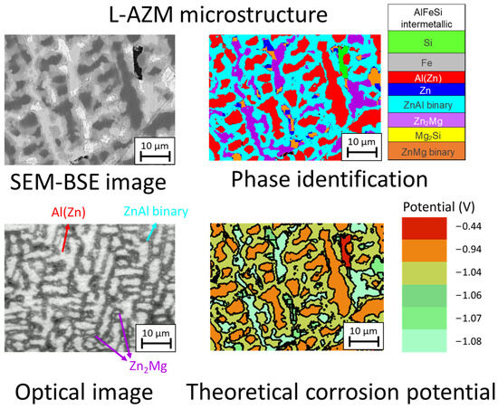
Figure 1.
Typical backscattered SEM and in situ optical images of a mirror-polished ZnAlMgSi coating (upper left) combined with corresponding phase recognition using the quantitative analysis of the SEM images(upper right image) and a map showing the distribution of the “theoretical” corrosion potentials (vs. SCE) expected from the electrochemical potential of individual phases in an NaCl environment (lower right image). The phase identification and theoretical corrosion potential distribution images are based on the SEM analysis, while the optical image was taken during in situ testing in a different area (lower left image).
Considering that optical reflection microscopy performs better on flat surfaces due to the reduced contribution of scattered light because of the reduced surface roughness, the samples were polished prior to the in situ reactivity tests to minimize the roughness and remove any surface oxides formed during storage. Two different sample configurations were studied. The first configuration was selected to study the intrinsic reactivity of the coating uncoupled to steel, allowing only contact between the coating and the electrolyte. For this configuration, the coating surface was polished in the plain of the coating (surface indicated as “surface polishing” in Figure 2). Slight polishing was applied only to the coating surface using abrasive SiC paper (grade 2500), followed by polishing with a diamond colloidal solution (particle size 3 µm and 1 µm) using ethanol as a lubricant.
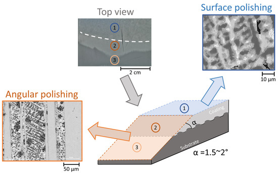
Figure 2.
Schematic representation and examples of the SEM images of two configurations of polished surfaces (surface polishing and angular polishing) before their exposure to the electrolyte. Surface polishing was used to model the initial corrosion of the uncoupled coating and the angular polishing to model the initial galvanic coupling in scratch. A macroscopic optical image of the interface polished at an angle is also shown. The dash white line is added to evidence the interface between the parts with different inclination (top surface and the inclined surface formed in the zone polished at an angle).
The second configuration was proposed to model galvanic coupling between the coating and the steel substrate in case of a defect inside the coating, leading to the formation of a scratch. The difficulty in creating such a model sample is that the high-resolution optical microscopy requires very low surface roughness, so cannot simultaneously measure the reactivity on the surface of the coating in the vicinity of the scratch and inside the scratch (which should be as deep as the coating to reach the steel substrate, so about 22 µm). Another difficulty for the understanding of the coating reactivity near the scratch, specific to the studied coating, is related to the presence of a gradient in the phase’s depth distribution (see [39]). So, for a mechanistic study, it seems more reliable to observe the reactivity for the microstructures of the coating when polished until there is close contact with the steel. Finally, to prepare steel–coating interfaces representative of the scratch and suitable for high-resolution optical reflection microscopy, an “angular polishing”, schematically shown in Figure 2, was proposed, which used polishing in a plane inclined by 1.5° to 2° to the coating surface.
2.2. In Situ Analysis
Reflective microscopy (RM) was conducted during the electrochemical measurements to observe, in situ, the corrosion phenomena using a setup described elsewhere [41,42]. A custom-made cylindrical cell was used for the measurements, with an exposed area of 1.4 cm2. For the experimental setup, an Olympus microscope equipped with a 40× magnification water immersion objective 1.00 NA, Olympus LUMPlanFLN W (Tokyo, Japan) was used, with a focal distance of 3.5 mm. The sample was illuminated from the top using a halogen white lamp, filtered to 490 nm blue light with an interference filter (spectral bandwidth of 20 nm). The image registration was made using a SVCam exo541MU3 CCD camera SVS-Vistek GmbH (Gilching, Germany), 4496 × 4504 pixels, 16-bit operating at 10–25 VDC. With these parameters, the expected linear pixel size was calculated as approximately 67.5 nm. The microscope objective was used to illuminate from the top, also collecting the reflected light and directing it into the CCD camera. This enables the real-time imaging of the reflected light from the sample’s surface [43]. To optimize the quality of the images, the planarity of the surface was ensured with a z precision of 10−2 degrees using an interference Mirau objective 10× magnification, CF Plan, Nikon, by minimizing the number of interference fringes over the imaged plane.
The experiments were conducted both in unbuffered 5 wt.% NaCl and 5 wt.% Na2SO4 aqueous solutions (using MilliQ water, Merck KgaA, Darmstadt, Germany, 18.2 M Ω × cm) with an initially neutral natural pH.
In both environments, the experiment was conducted in a similar way. First, the open-circuit voltage (EOC) was measured for 5 min and the value at the end of the measurement was considered for the following polarization. Then, 2 cycles of alternating anodic (30 s under the potential E = +50 mV vs. EOC) and cathodic (30 s under the potential E = −50 mV vs. EOC) polarization were applied, as illustrated in Figure 3. The potential was controlled and the electrochemical current under polarization was measured using a CHI 660A potentiostat (CH Instruments, Bee Cave, TX, USA). Thus, the total duration of the test was 420 s, including 120 s of polarization. The pictures were taken every 0.1 s during polarization. A stainless-steel wire and a leakless miniature Ag/AgCl electrode were used as counter and reference electrode, respectively. The choice for the reference electrode was dictated by the minimization of the electrolyte thickness in the cell to allow the best light recovery; thus, a leakless electrode is crucial to ensure that the concentration of chloride in the solutions is as targeted.
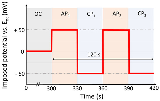
Figure 3.
Electrochemical cycle used during in situ tests. The cycle starts with 300 s of immersion at open-circuit (OC) potential, followed by two cycles of alternating anodic polarization (AP, applied potential E = +50 mV vs. EOC) and cathodic polarization (CP, applied potential E= −50 mV vs. EOC).
To ensure proper data analysis, image processing techniques, previously developed in ref. [43], were applied using the Python 3.9 virtual environment, with all codes freely available therein. The primary issue was the vibrations caused by the environment that generated noise during the manipulation. The correction was made by isolating a few particles in the whole sequence of images and using them as anchor points to align all the images. To understand how the corrosion evolved during the test, the optical response was measured over time. It was analyzed by extracting frames of optical data and normalizing them pixel-wise against the same frame at t = 0 s (reference). This normalization, achieved by calculating the ratio of each frame’s intensity to the reference frame and converting it to a percentage, helps in tracking small changes in the optical signal over time. The principle behind this approach is grounded in the Fresnel equation [44], which relates the reflectivity of light from a metal surface to the thickness and refractive index of surface films. These films, which form and change during corrosion, affect reflectivity and thus the optical signal. All original opto-electrochemical data are freely available in the Zenodo repository (https://doi.org/10.5281/zenodo.15831610).
2.3. Ex Situ Surface Characterization
The surface of the polished samples before and after corrosion was analyzed using a scanning electron microscope with a JEOL 7800F field emission gun (SEM-FEG) (JEOL, Tokyo, Japan) coupled with an XFlash 6l60 EDX detector from BRUKER (Ettlingen, Germany), with copper as a calibration element. The electron image acquisition was performed using backscattered electrons (BSE) mode. A voltage of 10 kV and a current of 3 nA were applied during the acquisitions. The elemental acquisitions were made over 300 s to increase the quality of the detection.
To assess the precise nature of the corrosion products in different locations, Raman microscopy analyses were performed using a Renishaw InVia Confocal Raman Microscope driven by WIRE 4.2 software. A green laser with a wave angle of 532 nm/2.33 eV type Nd-YAG double, a maximum power of 100 mW, and a spot size of 1 µm was used. Leica DM2500 50× objectives (NA 0.75) (Wetzlar, Germany) were used for the surface observation and selection of the zones of interest. The acquisition of each spectrum was made in 100 accumulations of 1 s and using a 1800 lined/mm grating. The acquisition conditions were carefully chosen to not degrade the surface of the material and not saturate the detector. To ensure the validity of the measurements, for each surface morphology on each studied area at least 4 different spectra were recorded from close but different locations and compared.
3. Results
3.1. Initial Microstructure and Initial Corrosion Behavior of an AlZnSiMg Coating Without Galvanic Coupling to Steel
The typical initial microstructure of the studied coating is illustrated in Figure 1 and was described in detail in our recent work [39]. Briefly, the major phases presented in the coating are binary ZnAl (44.6 ± 4.5% of area fraction on the cross section), Al(Zn) dendrites (32.5 ± 3.8%), and a pure Zn2Mg intermetallic phase (11.9 ± 2.3%). Minor phases were binary Zn/Zn2Mg and Si needles, both with an area fraction on the cross section of less than 3%, and Mg2Si, with a less than 1% area fraction on the cross section. Si is usually not present on the top surface of as-formed L-AZM but is concentrated in the lower part of the coating, closer to the substrate. In the studied surfaces, however, the application of polishing prior to the electrochemical experiments led to the exposure of several deeper-placed Si inclusions (green particle in Figure 1, upper right). One should also note that the local microstructure around the Zn2Mg phase in L-AZM was very different from the extensively studied microstructure of ZnAlMg coatings with lower Al contents [1,2,3,4,5,6]. For low-Al-containing ZnAlMg coatings, Zn2Mg is mainly present in the form of fine lamellar binary Zn/Zn2Mg and ternary Zn/Al/Zn2Mg eutectic phases; however, in the studied coating, coarse (with sizes of several microns and larger) particles of pure Zn2Mg were formed and surrounded by binary ZnAl. The difference in the local microstructure compared with the previously studied ZnAlMg coatings justifies a specific interest in the behavior of Zn2Mg in the new L-AZM coating.
The coating’s slightly polished surface demonstrated open-circuit potential values of around EOC = −1 V vs. Ag/AgCl in both chloride and sulfate environments. From Table 1, which provides the values of the potential measured at the beginning and at the end of 5 min of immersion, it can be seen that the potential decreases by 0.038 V in chloride and 0.018 V in sulfate, indicating a slight activation of the surface that is more pronounced in chloride. The cycling was performed using −0.95 V during the anodic polarization and −1.05 V during the cathodic polarization.

Table 1.
Open-circuit potential of the L-AZM coating in 5% wt.% NaCl and Na2SO4 electrolytes measured before (at the beginning and at the end of the 5 min immersion) and after the cycle of applied polarization.
Figure 4 shows the evolution of the electrochemical current in comparison with the average normalized reflectivity as a function of time. It can be seen that in the chloride solution the reflectivity continuously decreases (from 100% to 91%) until the first cathodic polarization. It slightly increases during the second anodic polarization (until 92%) but quickly reduces again. Furthermore, for this electrolyte, the electrochemical current values tend to stabilize at values of 1.25 mA and −0.25 mA during the anodic and cathodic cycles, respectively, for both the 1st and the 2nd polarization cycles. This indicates that the resistivity of the coating in this electrolyte does not change significantly during the experiment. On the other hand, in the sulfate electrolyte, a stronger darkening of the coating was observed, with a reduction of the reflectivity to 67% during the first anodic polarization and to 64% after the second anodic polarization. No significant changes were observed during the cathodic polarizations. Additionally, in contrast to the chloride environment, a significant decrease in the anodic current plateau between the first and the second polarization, from around 1.4 mA to 1.2 mA, indicates an increase in the resistivity of the surface, which could be related to the formation of a barrier of corrosion products.
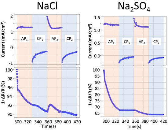
Figure 4.
Evolution of the measured electrochemical currents and average normalized reflectivity of the coating as a function of time during cycling in 5 wt.% NaCl or Na2SO4 aqueous solutions, as indicated. The external current is zero before the beginning of polarization, which started at 300 s, so the first time point shown in Figure 3 is 300 s.
The in situ images during polarization (Figure 5) show how different phases of the coating are consumed during the test. The quantitative reflectivity evolution over time, measured locally at selected phases, is also presented in the figure. In chloride, the variation in Al(Zn) is very small and Zn2Mg presents the most significant change with cycling. The binary ZnAl is dark even before polarization, indicating that corrosion has started in the open-circuit conditions. As it can be seen from both the local reflectivity evolution and the optical images in the zones highlighted by red circles, this phase becomes darker during the first cathodic polarization, with a loss of around 60% of the reflectivity; it becomes brighter again, with a reflectivity of 90%, during the second anodization and becomes darkened again to 45% of reflectivity for the second cathodic polarization. This indicates a strong sensitivity of the corrosion products formed in this phase to small changes in potential. In sulfate, there is a strong corrosion of the binary ZnAl during the first anodic polarization, and the reflectivity of this phase stabilizes at around 67%, with minor changes in the reflectivity throughout the rest of the test. The Zn2Mg particles present a darkening during both anodic polarizations, with a reduction in the reflectivity of around 25% and 10% respectively, and no significant changes during the cathodic polarizations. The Al(Zn) dendrites show a slight reduction in their reflectivity that occurs at a constant and low rate during the entirety of the test, reaching a final value of 80%, indicating the formation of corrosion products on their surfaces. Interestingly, the corrosion of lamellar binary Zn-Zn2Mg can be seen, with a preferential corrosion of the Zn2Mg lamella (Figure 6). The differentiation between the two phases is made by taking into consideration the lamellar size, in which zinc is coarser than the Zn2Mg. Another interesting observation is that the lamellar Zn2Mg corrodes earlier than the Zn2Mg particles.
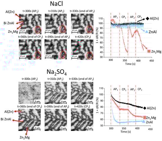
Figure 5.
High magnification of selected in situ images of the coating microstructure under polarization in 5 wt.% NaCl and 5 wt.% Na2SO4 electrolytes, as indicated, (left) and correspondent variations over time of the normalized local reflectivity measured for different phases, indicated as Al(Zn) for dendrites, bi ZnAl for binary Zn/Al(Zn), and Zn2Mg. The red circles in the upper figure highlight an alternating darkening and lightening of a Zn2Mg particle during cathodic–anodic cycles in the NaCl electrolyte.
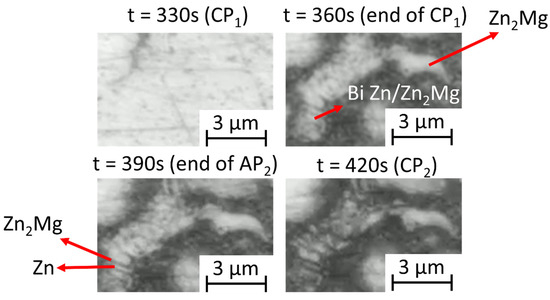
Figure 6.
Example of high-resolution images of the ZnAlMgSi coating in a Na2SO4 environment showing evolution of binary Zn/Zn2Mg during polarization cycling.
The observations also demonstrated, both in chloride and sulfate, that some gas bubbles formed at the surface. An illustration of this phenomenon is given in Figure 7. Bubbles are visible at the borders of the dendrites of Al. Although Si particles are not visually detected in the optical images, SEM-EDX cartography of the coating before the electrochemical test (Figure 5) reveals that Si particles can be present on the polished surface and the distance between particles has the same order of magnitude as the distance between the bubble formation centers. Si is strongly cathodic in comparison with the other phases of the coatings, with a potential of −0.44 V vs. SCE [26], and can therefore be considered as a cathodic area. Nevertheless, the Al(Zn) phase also remains cathodic to the binary ZnAl and Zn2Mg, with their corrosion potentials being −0.94 V [27], −1.04 V [26], and −1.09 V [26] vs. SCE, respectively. Thus, neither the Si nor the dendrites of Al can be excluded as the potential cathodic phases that take part in the formation of the bubbles.
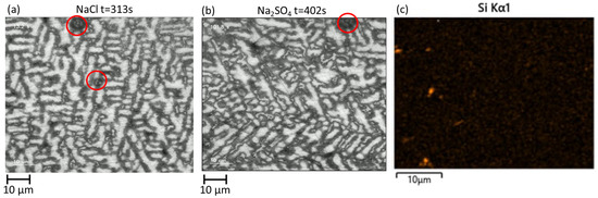
Figure 7.
Illustration of in situ images of gas bubble formation on the surface of the immersed coating under polarization (highlighted by the red circle) in chloride (a) and sulfate (b) environments, compared with a typical distribution of Si shown by an EDS map of Si on the slightly polished surface before electrochemical testing (c).
Table 2 shows the highest and the lowest current values measured during anodic and cathodic polarization, respectively. For the surface tests, the fact that when measured under anodic polarization the current is positive and when measured under cathodic polarization the current is negative indicates that, in this experiment, the open-circuit potential did not substantially vary during the short polarization time. At the same time, the values for the open-circuit potential measured 120 s after the end of the polarization (see Table 1, t = 540 s) demonstrate a slight activation of the surface in the chloride electrolyte (the potential decreases from −1.003 to −1.010 V vs. Ag/AgCl) but its passivation in sulfate electrolyte (the potential increases from −1.033 to −1.028 V vs. Ag/AgCl). In both cases, the open-circuit potential stabilization after the polarization was achieved in several seconds, which is much quicker than before the polarization.
Table 2.
The extreme values of the currents measured during anodic and cathodic cycles in 5% wt.% NaCl and Na2SO4 electrolytes with and without coupling with steel.
Both the current and reflectivity changes during the in situ tests confirm that the reactivity in the chloride electrolyte is higher overall, which is consistent with high corrosiveness of chloride ions for zinc-based phases [19], as well as their destabilizing effect on the passivation layer of aluminum [20]. More homogeneous darkening and the decrease in the electrochemical current under the second anodic polarization in sulfate (if compared to the first polarization), as well as the slight increase in the open-circuit potential after the experiment, indicate surface passivation in this electrolyte.
3.2. Corrosion Product Analyses After Initial Coating Corrosion Without Coupling to Steel
The in situ images clearly showed the darkening of most of the coating phases, indicating the formation of corrosion products. However, the darkening was not similar in the two electrolytes. While in sulfate all the phases became darker, especially during the first anodic polarization, in chloride, the Al(Zn) dendrites did not present any darkening. The results of surface analyses after the experiments help to understand the hypotheses regarding the formation of corrosion products on different phases and the nature of these products. The distribution of chemical elements on the coating surface after the test can be seen in the SEM-BSE image and the EDX mapping for the Zn, Al, Mg, Si, and O elements shown in Figure 8. In chloride, no O and, therefore, no corrosion products are detected at the surface of the dendrites via EDX, while the surface of the interdendritic zones seems fully oxidized. In the zone where the Si signal was intense, highlighted by the white circle, there are also strong signals for O, Zn, and Mg, indicating the deposition of corrosion products, which could be due to the pH increase at cathodic Si particles. In the case of sulfate, a homogeneous layer of corrosion products is visible on the entire surface. The distributions of Al and O also seem to be correlated, indicating the possible formation of Al-containing corrosion products.
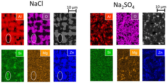
Figure 8.
SEM-EDX maps of Zn, Al, Mg Si, and O and the corresponding backscattered electron images of the ZnAlMgSi coating after the experiment in NaCl and Na2SO4 as indicated. The white circles in the NaCl image highlight the presence of a Si particle covered by Zn- and Mg-containing corrosion products.
To better understand the nature of these products, Raman spectra were acquired on different phases, as illustrated in Figure 9. The main corrosion products found after the tests in the chloride-rich electrolyte were ZnO and hydrozincite (Zn5(OH)3(CO3)) in the interdendritic zones. These compounds are commonly identified during the corrosion of Zn and Zn-Al coatings [8,22]. The literature reports the formation of layered double hydroxides and Mg-containing products in atmospheric conditions [3,9,45,46], but in this work, no Al-containing or Mg-containing corrosion products were found. This difference could be because in the present work the tests were conducted in an electrochemical cell with a large volume of the electrolyte and in a very short time, thus slowing the accumulation of the necessary species. One should also note that the characterization methods used are more adapted to the detection of precipitated products than to the detection of very thin or amorphous layers. Hence, the presence of thin (several monolayers) layers of oxides on Al and/or Mg cannot be excluded.
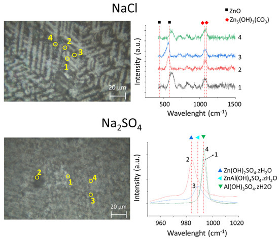
Figure 9.
Ex situ optical images of the ZnAlMgSi coating after polarization in 5 wt.% NaCl and Na2SO4 electrolytes, as indicated, (left) and typical Raman spectra (right) recorded in different areas (indicated by numbers in the optical images analyses). The selected points present four typical zones of the coating: (1) Al(Zn) dendrite, (2) Zn2Mg particle and (3) and (4) binary ZnAl.
In sulfate, zinc hydroxysulfates (Zn(OH)2SO4.zH2O), aluminum hydroxysulfates (Al(OH)3SO4.zH2O) and zinc–aluminum hydroxysulfates (ZnAl(OH)4SO4.zH2O) were mainly detected, with characteristic peaks shown in Figure 9. The aluminum hydroxysulfate was mainly detected on the surface of the dendrites, which agrees with a continuous reflectivity loss for the dendrites in the sulfate electrolyte, as shown in Figure 5. The fact that the electrochemical current measured under anodic polarization in the sulfate electrolyte decreased over time while the cathodic current was systematically lower in sulfate than in the chloride-rich electrolyte indicates that, on the one hand, cathodic reactivity is inhibited in the sulfate electrolyte compared to the chloride electrolyte, and, on the other hand, the inhibition enhances with the development of aluminum hydroxysulfates on the dendrites. Moreover, the fact that the open-circuit potential becomes more noble after the experiment also supports the idea of a barrier effect from the formed corrosion products. This supports the idea that the intrinsic coating corrosion is governed by the galvanic coupling between dendrites and interdendritic phases and that the Al(Zn) dendrite reactivity is strongly affected by the electrolyte composition via modification of the surface oxides.
3.3. Initial Corrosion Behavior of the AlZnSiMg Coating in a Configuration of Galvanic Coupling with Steel
The evolutions of the samples with angular polishing during the polarization tests are shown in Figure 10, Figure 11 and Figure 12. These evolutions allow us to simulate the corrosion processes near the localized damage of the coating up to the steel substrate. Figure 10 illustrates the general evolution of the steel/coating interface and the evolution of the electrochemical current measured under anodic and cathodic polarization. Figure 11 and Figure 12 present a more resolved microstructure evolution, showing in detail the preferential nucleation points and corrosion mechanisms.
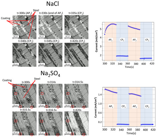
Figure 10.
In situ optical images showing the evolution of model steel/coating interfaces (left) and the measured evolution of the electrochemical current (right) during a cyclic polarization test in 5 wt.% NaCl and Na2SO4 solutions, as indicated. Red circles highlight the preferential corrosion nucleation points in sulfate environment.
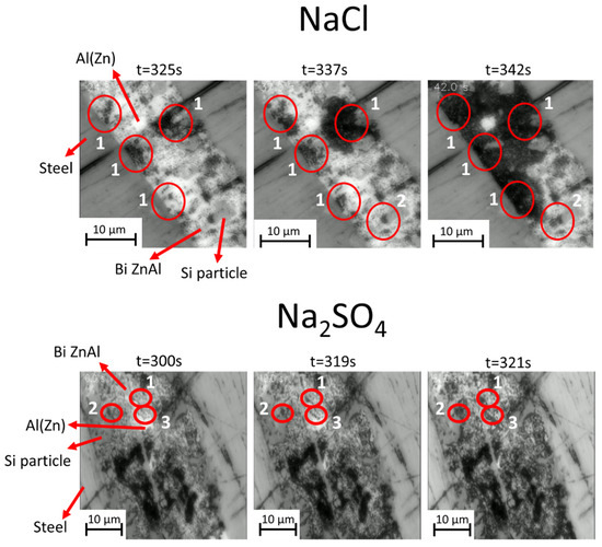
Figure 11.
High-magnification in situ optical images showing the evolution of the model steel/coating interface during cyclic polarization in 5 wt.% NaCl and Na2SO4 electrolytes. Red circles show corrosion initiation at (1) the interface of binary ZnAl with steel, (2) the binary ZnAl interface with Si particles, and (3) the interface of steel with an Al(Zn) dendrite.
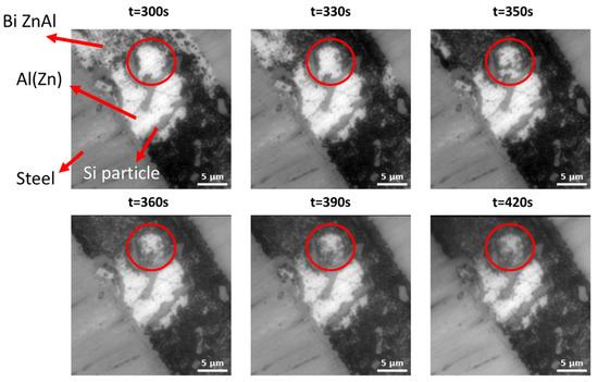
Figure 12.
High-magnification in situ optical images of the model steel/coating interface during cyclic polarization in the 5 wt.% NaCl electrolyte, showing the initial corrosion of interdendritic phases, followed by dendrite pitting (highlighted by red circles), in particular when in contact with Si.
By comparing Figure 4 and Figure 10, it can be concluded that, when the contact with the substrate exists, the anodic current density is higher in comparison to the uncoupled coating. The maximal values are also reported in Table 2. One should note that for the angular polishing sample configuration, the values of the external electrochemical current are not meaningful. First, the system contains large cathodic (steel) and anodic (coating) zones with no exact rational distribution among them or rigorous control, allowing charge transfer processes outside of the external circuit. Unfortunately, in the present case, the effect of this galvanic coupling on the total external current cannot be quantitatively evaluated because of the significant roughness of the initial steel/coating interface, which does not allow proper control of the ratio between the anodic and cathodic areas in the angular polishing scenario. Second, corrosion and the formation of corrosion products on both the cathodic and anodic areas during the experiment can further modify the OCP, even in the 300 s polarization times used in this work. As a result of these factors, the name of the cycle stages as “anodic polarization” (AP) and “cathodic polarization” (CP), which refers to the initially fixed EOC value, becomes less relevant, and the fact that the total current stays positive under applied potential even if it is 50 mV lower than the measured EOC confirms the difficulties regarding the electrochemical signal interpretation. Still, a slight decrease in the anodic current under anodic polarization could indicate the formation of passivating corrosion products.
The details of phase consumption and corrosion product propagation appear more reliable, as they are locally resolved and directly reflect the local current distribution. In the images shown in Figure 10, in chloride environment, the corrosion front advances over time in one direction (see the darkening from the top-right towards the bottom-left of the images), while in sulfate, it is harder to define a specific direction for the propagation of the corrosion front. The irregularities observed at the interface of the coating/substrate are due to the roughness of the substrate and the diffusion process that occurs during the solidification of the coating. Similarly to the corrosion of the uncoupled coating, it seems that the corroded coating morphology and distribution of the corrosion products in the configuration of galvanic coupling with the steel substrate is more homogeneous in the Na2SO4 electrolyte than in the NaCl electrolyte. In sulfate, the corrosion products are formed uniformly on all the phases during the first cathodic polarization, except for the pure Si phase. In both electrolytes, several types of corrosion initiation and propagation sites appear, which are shown at higher magnification in Figure 11. Corrosion propagates first from the interface of the steel/sacrificial phases (typically ZnAl and eutectic phases) in both electrolytes, as can be seen in the zones highlighted by circles numbered 1. Later, the interfaces inside the coating become reactive and notably close to the Si particles, as highlighted by circles numbered 2. Corrosion initiation at the interfaces between the binary Zn/Al and the dendrites of Al is, however, detected only in sulfate (an example of the zone shown by circles numbered 3 in Figure 11). One should note that Si particles that were not visible by optical imaging but only detected by SEM for the surface polishing appear as an important phase close to the steel.
Figure 12 presents a magnified view of the in situ evolution of an Al(Zn) dendrite in direct contact with the substrate and Si particles in a NaCl electrolyte. One can see that in the initial steps of corrosion, the interdendritic phases are mainly covered with corrosion products. As corrosion progresses, pits appear on the surface of Al(Zn) dendrites, beginning in the areas close to the interfaces with Si particles. This is cosistent with the suggestion made in [23] that Si can act as a cathodic activator of Al dendrite pitting in chloride-containing electrolytes.
To summarize, the in situ tests demonstrated that in both electrolytes, the phase consumption follows the order binary ZnAl > binary Zn2Mg/Zn > Zn2Mg > Al(Zn). This order, however, does not reflect the fact that Al(Zn) dendrites initially react in sulfate electrolyte, allowing the formation of aluminum hydroxysulfates, which strongly reduce the reactivity of the dendrites and, as a consequence, also the galvanic coupling between the phases and the coating’s consumption rate. The formation of homogeneous zinc and aluminum hydroxysulfates on the surface of the coating also contributes to the slower overall coating consumption in the sulfate electrolyte than in the chloride electrolyte.
In the NaCl electrolyte, the dendrites were not initially sacrificial, but their pitting was observed at more advanced corrosion stages in configurations when the coating was coupled to the substrate steel. In this configuration, corrosion initiated and propagated due to the coupling of the sacrificial phases with the substrate steel but also with Si particles in both electrolytes.
The tests also demonstrated the complex reactivity of the Zn2Mg particles in comparison to the other sacrificial phases of the coating, with corrosion products being strongly sensitive to the polarization condition.
4. Discussion
4.1. Initial Stages of Corrosion in Different Electrolytes: Intrinsic Coating Reactivity
The most surprising result of this work is that the binary ZnAl significantly corrodes even under open-circuit conditions and is the most reactive phase of the coating in both environments. Based on prior knowledge, it could be expected that the most reactive phase would be Zn2Mg, which exhibits the lowest corrosion potential in a chloride environment (E = −1.08–−1.09 V vs. SCE [26]) and which is also known to be the first consumed in ZnAlMg coatings [36,37,38]. The fact that in both environments Zn2Mg, which is the most anodic phase, starts to react later than the binary ZnAl in the present work is appealing. Moreover, the reactivity of monophase Zn2Mg intermetallics starts later than the consumption of the Zn2Mg/Zn lamellar eutectic phase. To explain the high reactivity of binary ZnAl, its fine structure needs to be considered; ZnAl consists of fine globular Al(Zn) needles in a zinc matrix. Such a phase microstructure presents the highest possibility of internal microgalvanic coupling, enhancing its reactivity. In the case of the lamellar eutectic, there is the coupling between the zinc and the Zn2Mg phase, which is also important for the reactivity. The potentials of the Al- and Zn-rich phases in binary ZnAl are more distinct than the potentials of Zn2Mg and Zn in binary eutectics, which could explain the higher reactivity of ZnAl than ZnMg phases in the studied alloy. These observations highlight the importance of the reactivity of not only the phase electrochemical potentials but also their distribution in the microstructure.
The accumulation of Zn-based corrosion products is also consistent with the selective dissolution of Zn from Zn-rich phases owing to their low electrochemical potential and local microstructure in the L-AZM coating:
Fine Al inclusions from the binary ZnAl could be detached because of zinc matrix dissolution but are not expected to react in initially neutral solutions. Nonetheless, our results do not allow to conclude if the residual Al from the binary phase is indeed detached and in the solution or remains on the surface. The accumulation of soluble zinc, however, should lead, thanks to the alkalinity increase by cathodic oxygen reduction (reaction (1)), to the precipitation of zinc corrosion products, for instance by reaction (3).
Another important observation comes from the effect of the electrolyte on the distribution of corrosion products around the dendrites and their effect on the reactivity of the dendrites. While, overall, the dendrites remained reflective and no corrosion products were detected on Al(Zn) dendrites on the surface of the coating exposed with or without polarization in chloride electrolyte, they continuously darkened in the sulfate environment and aluminum hydroxysulfates were detected on dendrites and zinc–aluminum hydroxysulfates were detected in interdendritic phases. The formation of these products is consistent with the literature [47], and the formation of aluminum hydroxysulfates and AlZn hydroxysulfates is known to improve both short- and long-term corrosion resistance [9,48], justifying the reduction in the current observed after the deposition of the corrosion products.
The anodic and cathodic reactions of the coating and the precipitation of corrosion products owing to these reactions are schematically shown in Figure 13, with the Al dendrite acting as an initial cathode for the coating (left) part of each figure.
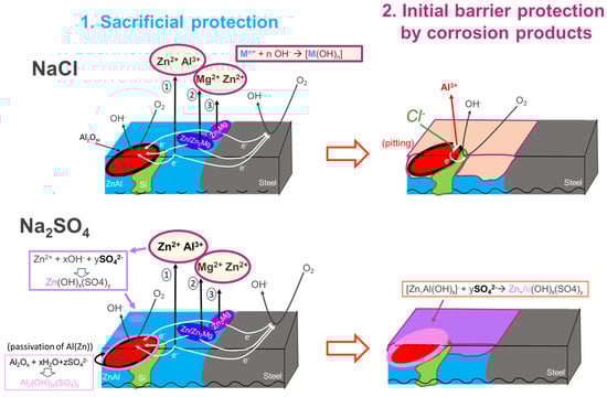
Figure 13.
Summary of the corrosion mechanisms in chloride and sulfate for the L-AZM coating, indicating both the initial sacrificial protection by the different phases and the barrier effect provided by the corrosion products in both NaCl and Na2SO4, as indicated.
Zn2Mg also demonstrated different behavior between the two electrolytes. In chloride, this phase darkened during the first polarization cycle; however, it became lighter under the second anodic polarizations and reformed under the second cathodic polarization. The fact that corrosion products were formed under a cathodic reaction suggests that they are stable only under the high pH conditions generated by the oxygen reduction reaction (1). The local alkalinity can decrease under anodic polarization because of both the diffusion and hydrolysis of dissolved zinc ions.
Taking into account the fact that Zn corrosion products are stable at neutral pH values but not at alkaline pH values, while Mg corrosion products, in particular Mg(OH)2, dissolve at pH values below 10, one could suggest that the product formed on Zn2Mg during the initial stages of corrosion in the NaCl electrolyte would be Mg(OH)2. This compound is known to not accumulate in large quantities but instead act as a source of Mg ions, favoring the stability of different zinc corrosion products versus their dissolution under in high-pH environments or in the presence of an excess of other complexes forming anions [8,9,49,50]. The fact that in the sulfate electrolyte the darkening occurred mainly in anodic phase but did not increase under cathodic polarization suggests that the corrosion products formed on Zn2Mg in the sulfate electrolyte precipitate at neutral pH values, so maybe mainly Zn-based. Zinc and zinc–aluminum hydroxysulfates were indeed found on all the interdendritic areas. The source of Al may be attributed to the initially higher reactivity of Al in sulfate electrolyte.
Considering the coating as a whole, the evolution of its reflectivity and the electrochemical current can be interpreted in terms of the stability of the corrosion products and their barrier effect. From this point of view, the corrosion products formed in sulfate electrolytes are more stable and have more of a barrier effect than the products formed in chloride. The presence of stable corrosion products on the AlZnMgSi coating in the sulfate electrolyte is consistent with the lower current observed during electrochemical measurements and with the results reported in the literature [15]. The instability of the corrosion products formed on AZ and AZ-2% Mg coatings in chloride electrolytes was also reported in the literature [51].
4.2. Initial Stages of Corrosion in Different Electrolytes: Sacrificial Protection of Steel
The main objective of the “scratched” samples was to enhance the corrosion of the coating, as well as observe how the coupling with the steel may affect coating reactivity and sacrificial protection mechanisms. In sulfate, the reactivity of the coating seems to propagate homogeneously (Figure 10). At high magnifications (Figure 12), it can be seen that the reactivity starts from all of the interfaces between the Zn- or Al-containing phases (including dendrites Al(Zn)) and the steel or Si particles, confirming that all the Zn-Al-Mg-containing phases in this electrolyte participate in sacrificial protection, while Si particles contribute to premature coating consumption. Corrosion products seem to cover all the interfaces between the coating phases and steel, which is expected to increase the duration of the protection.
In chloride, at high magnification (Figure 11) it is possible to detect that the reactivity nucleates at the interface between the binary phases and the steel, as well as at the interfaces with the particles of Si. Similarly to the observations made for uncoupled coating, corrosion product deposition in chloride happens preferentially at the interdendritic phases, leaving the dendrites uncovered High-resolution images also allow the first in situ observation of the initial corrosion of Al(Zn) dendrites via a pitting mechanism when in contact with Si particles in a chloride electrolyte.
4.3. Summary of the Corrosion Mechanisms
Figure 13 schematically sums up the mechanism of the initial corrosion and sacrificial protection of steel by an Al-rich quaternary ZnAlMgSi coating, proposed on the basis of the presented results. Considering the differences in the electrochemical potential and the presence of microgalvanic coupling, the binary ZnAl and Zn/Zn2Mg phases are considered the most sacrificial, while the dendrites of Al(Zn) are the least sacrificial and Si is the most noble. With respect to the order of the phase consumption, binary ZnAl, then lamellar eutectic Zn/Zn2Mg, then Zn2Mg, and finally dendrites of Al(Zn) can be anodically consumed. Cathodic reactions on steel, Si particles, and Al dendrites will generate local pH increases, leading to the precipitation of corrosion products. Since Zn-rich phases corrode first, the corrosion products are expected initially to precipitate in the areas close to Zn-rich phases. As for Al, which is expected to form a natural oxide film, a high local pH on dendrites can lead to partial oxide dissolution [52]; an initial anodic dissolution is also possible in sulfate [48]. This initial Al dissolution can be a source of Al ions for the formation of Al-containing hydroxysulfates (see Figure 9), while in chloride the oxides are attacked only locally. When Cl− is present, no soluble Al is available and zinc-based corrosion products form in interdendritic areas.
The barrier effect of basic salts of Zn and Al, including hydroxisulfates and layered double hydroxides, have been largely discussed for Zn [53], low-Al-containing ZnAl and ZnAlMg coatings [8,9,10,24,36,45,54,55], and Al-Si coatings [47,48]. However, the corrosion products formed on quaternary coatings with Al contents between 30 and 50% have not yet been studied, nor has the correlation between the local microstructure and the barrier effect of the formed corrosion products been considered. The knowledge regarding the initially formed corrosion products for the studied L-AZM coating is therefore new and helpful. Because of this information, we can propose some hypotheses about the effect of these products on the corrosion and protection of L-AZM-coated steel at more advanced stages of corrosion. When zinc-rich interdendritic phases are consumed, in chloride environments, Al dendrites could still provide sacrificial protection to steel via a pitting mechanism, while in sulfate, at this stage they could be protected by the corrosion products and will probably no longer be sacrificial. In contrast, with sulfate environments being significantly less aggressive for Zn and the barrier corrosion products being more stable and more uniformly distributed, a much longer time is expected before the interdendritic phases are consumed.
5. Conclusions
The initial corrosion behavior of a multiphase ZnAlMgSi coating, alone and in galvanic coupling with the substrate steel, was analyzed by coupled electrochemical measurements and high-resolution in situ optical reflection microscopy during anodic (+50 mV vs. OCP) and cathodic (−50 mV vs. OCP) polarization cycles in 5 wt.% NaCl and in 5 wt.% Na2SO4. Optical microscopy allowed us to observe the behavior of the different phases of the coating (dendrites of Al(Zn) and the different phases present in the interdendritic zones (binary ZnAl, lamellar binary Zn/Zn2Mg as well as isolated Zn2Mg, and pure Si phases in the interdendritic zones) and visualize homogeneous or localized formation of corrosion products. Combining in situ opto-electrochemical analysis and ex situ chemical analysis of the corrosion product distribution by SEM-EDX and Raman microscopy, the following conclusions can be drawn:
- The initial reactivity of the phases in the studied Al-rich (>30 wt.% of Al) composition of the ZnAlMgSi coating is observed to be in the order binary ZnAl > binary Zn/Zn2Mg > Zn2Mg > Al(Zn) dendrites. This order does not follow the order of the corrosion potentials reported in the literature and differs from the order known in the literature for ZnAlMg alloys with lower Al contents (up to 11 wt.%), for which the Zn2Mg phase was systematically reported as the first to be consumed and to participate in corrosion product formation. The observed behavior can be explained by differences in the shapes, sizes, and neighborhoods of the phases, resulting in different microgalvanic couplings. These results strongly highlight that the coatings formed by the same phases can show different reactivity and that a simple knowledge of the electrochemical potential of the individual phases is insufficient to predict their behavior. A detailed understanding of the microstructure is necessary to understand complex quaternary coatings.
- The reactivity of Al(Zn) dendrites seems to be complex and depends on the environment. If only the coating is exposed, Al(Zn) reacts anodically in the first seconds of polarization in sulfate electrolyte, which is confirmed both by the in situ observed surface darkening and the presence of Al hydroxysulfates on Al(Zn). The formation of this product seems to passivate the dendrites, decreasing their reactivity in the following polarization cycling. In contrast, in the chloride environment, the Al(Zn) dendrites did not show any significant initial reactivity, and no corrosion product was formed.
- In chloride, no corrosion products were detected on the surface of the Al(Zn) dendrites either in situ by high-resolution reflection microscopy or ex situ by SEM-EDX and Raman microscopy. The most noticeable in situ changes happened at the surface of the Zn2Mg phase, and most of the products formed on it during the first cathodic polarization were dissolved during the second anodic polarization, indicating a necessity to maintain high pH for their stabilization and suggesting the initial formation of magnesium hydroxide, which stable only at high pH values. After the end of the full cycle, the main detected corrosion products were ZnO and hydrozincite, which were located on interdendritic phases.
- In Na2SO4, the whole surface evolved during the experiment and there was homogeneous precipitation of corrosion products. Ex situ observations confirmed the presence of Al-containing corrosion products on different phases. Raman analyses identified Al hydroxysulfates (Al(OH)3SO4.zH2O) as the main corrosion products on Al(Zn) dendrites and Zn hydroxysulfates (Zn(OH)2SO4.zH2O) and Zn-Al hydroxysulfates (ZnAl(OH)4SO4.zH2O) as the main products formed on interdendritic phases. These compounds were previously reported to provide good barrier protection for Al or Zn. However, their stability over time remains unexplored.
- The electrochemical current changes during cycling were different for the two electrolytes. In chloride, the same current density was measured during the first and the second anodic cycles. In sulfate, a clear decrease in the current density between the cycles was measured, which can be interpreted in terms of the formation of barrier corrosion products, resulting in a decrease in surface reactivity.
- Isolated zones of small gas bubble formation were evidenced by in situ microscopy under an anodic polarization of +50 mV vs. OCP of the coating (close to −1.0 V vs. Ag/AgCl). This potential remains cathodic for the pure Si phase, and the distance between the bubbling zones correlated in order of magnitude with the distance between the Si particles measured by the SEM-EDX mapping of the samples. Hence, gas bubbling was correlated with the presence of the Si phase, which stays cathodic regarding all the other phases and the steel substrate in both electrolytes.
- In situ observation of the model steel–coating interfaces in the two electrolytes also revealed the differences in the sacrificial reactivity of the coating. In chloride, Al(Zn) dendrites and their interfaces with steel or interdendritic phases stayed intact and the reactivity was initiated at the interfaces between the interdendritic Zn-rich phases and steel or between the interdendritic Zn-rich phases and Si inclusions. In sulfate, initial reactivity points appeared immediately at the interface between the Al(Zn) dendrites and the binary ZnAl.
- The observed tendencies describe only the initial reactivity. The formation of corrosion products, as in the case of the products on Al(Zn) dendrites in sulfate media, can significantly modify the subsequent corrosion behavior. Further in situ studies of more advanced stages of corrosion are necessary to optimize long-term steel protection by these new coatings.
Author Contributions
Conceptualization, T.M.A., P.V. and V.S.; methodology, T.M.A., G.A.C.S., V.S., O.G. and P.V.; software, V.S. and O.G.; validation, T.M.A., G.A.C.S., V.S. and P.V.; formal analysis, G.A.C.S. and O.G.; investigation, G.A.C.S. and O.G.; resources, T.M.A., P.V. and V.S.; data curation, G.A.C.S. and O.G.; writing—original draft preparation, G.A.C.S. and P.V.; writing—review and editing, G.A.C.S., T.M.A., V.S. and P.V.; visualization, G.A.C.S., V.S. and P.V.; supervision, T.M.A., V.S. and P.V. All authors have read and agreed to the published version of the manuscript.
Funding
This research was partly supported by the French National Agency for the Research and Technology (ANRT), with the contract number CIFRE 2022/0196. The funder was not involved in the study design, collection, analysis, interpretation of data, the writing of this article or the decision to submit it for publication.
Data Availability Statement
The raw data supporting the conclusions of this article will be made available by the authors on request.
Acknowledgments
O.G. would like to thank Alexei Makogon for help with the data processing. V.S. thanks the French National Agency for the Research ANR JCJC program (OCTAWA project, ANR-22-CE29-0010-01) for the partial financial support for the upgrading of the optical setup.
Conflicts of Interest
Authors Guilherme Adinolfi Colpaert Sartori and Tiago Machado Amorim were employed by the company ArcelorMittal Research SA. The remaining authors declare that the research was conducted in the absence of any commercial or financial relationships that could be construed as a potential conflict of interest.
References
- Luba, M.; Mikolajczyk, T.; Pierozynski, B. Comparison of the Corrosion Resistance of Commercial coated steel and hot-dip Zn Coatings under Changing Environmental Conditions. Int. J. Electrochem. Sci. 2019, 14, 10306–10317. [Google Scholar] [CrossRef]
- Komatsu, A.; Tsujimura, T.; Watanabe, K.; Yamaki, N.; Andoh, A.; Kittaka, T. Hot_dip Zn–Al–Mg Coated Steel Sheet Excellent in Corrosion Resistance and Surface Appearance and Process for the Production Thereof. Patent EP0905270, 31 March 1999. [Google Scholar]
- Tsujimura, T.; Komatsu, A.; Andoh, A. Influence of Mg content in coating layer and coating structure on corrosion resistance of hot-dip Zn–Al–Mg–Si alloy coated steel sheet. In Proceedings of the Galvatech ’01, International Conference on Zinc and Zinc Alloy Coated Steel, Brussels, Belgium, 26–28 June 2001; pp. 145–152. [Google Scholar]
- Tanaka, S.; Honda, K.; Takahashi, A.; Morimoto, Y.; Kurosaki, M.; Shindo, H.; Nishimura, K.; Sugiyama, M. The performance of Zn–Al–Mg–Si hot-dip galvanized steel sheet. In Proceedings of the Galvatech ’01, International Conference on Zinc and Zinc Alloy Coated Steel, Brussels, Belgium, 26–28 June 2001; pp. 153–160. [Google Scholar]
- Sohn, I.-R.; Kim, T.-C.; Ju, G.-I.; Kim, M.-S.; Kim, J.-S. Development of PosMAC® Steel and Its Application Properties. Korean J. Met. Mater. 2021, 59, 613–623. [Google Scholar] [CrossRef]
- Monnoyer, M.; Corlu, B.; Amorim, T.M.; Dosdat, L.; Dieu, C. Interest of new generation Zn-Al3.7-Mg3.0 coatings for the industry and construction market. In Proceedings of the 10th International Conference on Zinc and Zinc Alloy Coated Steel Sheet (Galvatech 2015), Association for Iron & Steel Technology, Toronto, ON, Canada, 31 May–4 June 2015; pp. 231–238. [Google Scholar]
- Nicard, C.; Allély, C.; Volovitch, P. Effect of Zn and Mg alloying on microstructure and anticorrosion mechanisms of Al-Si based coatings for high strength steel. Corros. Sci. 2019, 146, 192–201. [Google Scholar] [CrossRef]
- Thébault, F.; Vuillemin, B.; Oltra, R.; Allely, C.; Ogle, K.; Heintz, O. Influence of magnesium content on the corrosion resistance of the cut-edges of Zn–Mg-coated steel. Corros. Sci. 2015, 97, 100–106. [Google Scholar] [CrossRef]
- Volovitch, P.; Vu, T.N.; Allély, C.; Abdel Aal, A.; Ogle, K. Understanding corrosion via corrosion product characterization: II. Role of alloying elements in improving the corrosion resistance of Zn–Al–Mg coatings on steel. Corros. Sci. 2011, 53, 2437–2445. [Google Scholar] [CrossRef]
- Schuerz, S.; Fleischanderl, M.; Luckeneder, G.H.; Preis, K.; Haunschmied, T.; Mori, G.; Kneissl, A.C. Corrosion behaviour of Zn–Al–Mg coated steel sheet in sodium chloride-containing environment. Corros. Sci. 2009, 51, 2355–2363. [Google Scholar] [CrossRef]
- Borzillo, A.R.; Crowley, J.E.; Horton, J.B. Ferrous Metal Article Coated with an Aluminum Zinc Alloy. U.S. Patent US3343930A, 26 September 1967. [Google Scholar]
- Panossian, Z.; Mariaca, L.; Morcillo, M.; Flores, S.; Rocha, J.; Peña, J.J.; Herrera, F.; Corvo, F.; Sanchez, M.; Rincon, O.T.; et al. Steel cathodic protection afforded by zinc, aluminium and zinc/aluminium alloy coatings in the atmosphere. Surf. Coat. Technol. 2005, 190, 244–248. [Google Scholar] [CrossRef]
- Odnevall Wallinder, I.; Leygraf, C. A Critical Review on Corrosion and Runoff from Zinc and Zinc-Based Alloys in Atmospheric Environments. Corrosion 2017, 73, 1060–1077. [Google Scholar] [CrossRef]
- Ding, Z.-L.; Yan, B.-H.; Jin, X.-Y.; Wang, X.-J.; Zhang, J.; Jiang, S.-M.; Zhang, Q.-F. Effect of magnesium on the microstructure and corrosion resistance of 55% Al-Zn coating. In Proceedings of the 12th International Conference on Zinc and Zinc Alloy Coated Steel Sheet (Galvatech 2021), Austrian Society for Metallurgy and Materials, Virtual, 22–24 June 2021; pp. 164–171. [Google Scholar]
- Wang, J.; Han, D.; Qiao, Z.; Zheng, Z.; Ma, R.; Du, A.; Fan, Y.; Zhao, X.; Yu, H.; Cao, X. Study on the microstructure and corrosion resistance of hot-dip Al-Zn-Si-xMg coating. Surf. Coat. Technol. 2025, 496, 131654. [Google Scholar] [CrossRef]
- Morimoto, Y.; Honda, K.; Nishimura, K.; Tanaka, S.; Takahashi, A.; Scindo, H.; Kurosaki, M. Excellent corrosion-resistant Zn–Al–Mg–Si-Si alloy hot-dip galvanized steel sheet ‘‘Super Dyma”. Nippon Steel Tech. Rep. 2003, 87, 24–26. [Google Scholar]
- Nippon Steel Corporation. ZEXEEDTM|Steel Sheets. Available online: https://www.nipponsteel.com/en/product/zexeed/ (accessed on 18 March 2024).
- Zhang, X.G. Corrosion and Electrochemistry of Zinc; Springer Science & Business Media: New York, NY, USA, 1996. [Google Scholar]
- Marder, A.; Goodwin, F. The Metallurgy of Zinc Coated Steels; Elsevier: Amsterdam, The Netherlands, 2023. [Google Scholar]
- Parangusan, H.; Bhadra, J.; Al-Thani, N. A review of passivity breakdown on metal surfaces: Influence of chloride- and sulfide-ion concentrations, temperature, and pH. Emergent Mater. 2021, 4, 1187–1203. [Google Scholar] [CrossRef]
- Moreira, A.R.; Panossian, Z.; Camargo, P.L.; Moreira, M.F.; Silva, I.C.d.; de Carvalho, J.E.R. Zn/55Al coating microstructure and corrosion mechanism. Corros. Sci. 2006, 48, 564–576. [Google Scholar] [CrossRef]
- Ho, C.Y.; Wang, J.Y. Investigation of microstructure related to corrosion evolution, mechanical and electrochemical properties on doped Si of binary Zn–Al coating. Mater. Chem. Phys. 2023, 301, 127656. [Google Scholar] [CrossRef]
- Pritzel Dos Santos, A.; Manhabosco, S.M.; Rodrigues, J.S.; Dick, L.F.P. Comparative study of the corrosion behavior of galvanized, galvannealed and Zn55Al coated interstitial free steels. Surf. Coat. Technol. 2015, 279, 150–160. [Google Scholar] [CrossRef]
- Kania, H.; Marek, A. Corrosion Behavior of Zn-Al-Mg-Si Coatings in Sulfur Dioxide-Containing Environment. Appl. Sci. 2024, 14, 2120. [Google Scholar] [CrossRef]
- Rosalbino, F.; Carlini, R.; Parodi, R.; Zanicchi, G.; Scavino, G. Investigation of passivity and its breakdown on Fe3Al–Si and Fe3Al–Ge intermetallics in chloride-containing solution. Corros. Sci. 2014, 85, 394–400. [Google Scholar] [CrossRef]
- Birbilis, N.; Buchheit, R.G. Electrochemical Characteristics of Intermetallic Phases in Aluminum Alloys: An Experimental Survey and Discussion. J. Electrochem. Soc. 2005, 152, B140. [Google Scholar] [CrossRef]
- Li, J.; Dang, J. A Summary of Corrosion Properties of Al-Rich Solid Solution and Secondary Phase Particles in Al Alloys. Metals 2017, 7, 84. [Google Scholar] [CrossRef]
- Mouanga, M.; Berçot, P. Comparison of corrosion behaviour of zinc in NaCl and in NaOH solutions; Part II: Electrochemical analyses. Corros. Sci. 2010, 52, 3993–4000. [Google Scholar] [CrossRef]
- Nicard, C. Mécanismes de Corrosion d’aciers Revêtus par AlSi(ZnMg). Ph.D. Thesis, Paris Sciences et Lettres (ComUE), Paris, France, 2018. Available online: https://theses.fr/2018PSLEC006 (accessed on 13 December 2024).
- Lemineur, J.-F.; Wang, H.; Wang, W.; Kanoufi, F. Emerging Optical Microscopy Techniques for Electrochemistry. Annu. Rev. Anal. Chem. 2022, 15, 57–82. [Google Scholar] [CrossRef]
- Shkirskiy, V.; Kanoufi, F. Reflective microscopy for mechanistic insights in corrosion research. Curr. Opin. Electrochem. 2023, 39, 101259. [Google Scholar] [CrossRef]
- Yang, Y.; Scenini, F.; Curioni, M. A study on magnesium corrosion by real-time imaging and electrochemical methods: Relationship between local processes and hydrogen evolution. Electrochim. Acta 2016, 198, 174–184. [Google Scholar] [CrossRef]
- Mopon, M.; Mol, A.; Garcia, S.J. Effect of delayed inhibitor supply on AA2024-T3 intermetallic activity: A local in situ analysis with reflected microscopy. Corros. Sci. 2024, 230, 111910. [Google Scholar] [CrossRef]
- Raffin, F.; Makogon, A.; Kanoufi, F.; Echouard, J.; Shkirskiy, V.; Volovitch, P. Initial cathodic reactivity of intermetallic particles in 7175 aluminum alloy buried under 6 µm thick anodized oxide layer revealed by in-situ reflective microscopy. Electrochimica Acta 2024, 492, 144155. [Google Scholar] [CrossRef]
- Denissen, P.J.; Homborg, A.M.; Garcia, S.J. Interpreting Electrochemical Noise and Monitoring Local Corrosion by Means of Highly Resolved Spatiotemporal Real-Time Optics. J. Electrochem. Soc. 2019, 166, C3275. [Google Scholar] [CrossRef]
- Persson, D.; Thierry, D.; LeBozec, N. The Effect of Microstructure on Local Corrosion Product Formation during Initial SO2-Induced Atmospheric Corrosion of ZnAlMg Coating Studied by FTIR-ATR FPA Chemical Imaging. Corros. Mater. Degrad. 2023, 4, 503–515. [Google Scholar] [CrossRef]
- Wint, N.; Cooze, N.; Searle, J.R.; Sullivan, J.H.; Williams, G.; McMurray, H.N.; Luckeneder, G.; Riener, C. The Effect of Microstructural Refinement on the Localized Corrosion of Model Zn-Al-Mg Alloy Coatings on Steel. J. Electrochem. Soc. 2019, 166, C3147. [Google Scholar] [CrossRef]
- Sullivan, J.; Mehraban, S.; Elvins, J. In situ monitoring of the microstructural corrosion mechanisms of zinc–magnesium–aluminium alloys using time lapse microscopy. Corros. Sci. 2011, 53, 2208–2215. [Google Scholar] [CrossRef]
- Adinolfi Colpaert Sartori, G.; Remy, B.; Machado Amorim, T.; Volovitch, P. Quantitative Microstructure of Multiphase Al-Zn-Si-(Mg) Coatings and Their Effects on Sacrificial Protection for Steel. Metals 2025, 15, 476. [Google Scholar] [CrossRef]
- Benzbiria, N.; Tran, T.T.M.; Kendig, M.W.; Zertoubi, M.; Qafsaoui, W. Cathodic behavior of pure Al in sulfate media. Int. J. Corros. Scale Inhib. 2019, 8, 385–410. [Google Scholar] [CrossRef]
- Chakri, S.; Patel, A.N.; Frateur, I.; Kanoufi, F.; Sutter, E.; Long, M.T.T.; Tribollet, B.; Vivier, V. Imaging of a Thin Oxide Film Formation from the Combination of Surface Reflectivity and Electrochemical Methods. Anal. Chem. 2017, 89, 5303. [Google Scholar] [CrossRef] [PubMed]
- Godeffroy, L.; Makogon, A.; Gam Derouich, S.; Kanoufi, F.; Shkirskiy, V. Imaging and Quantifying the Chemical Communication between Single Particles in Metal Alloys. Anal. Chem. 2023, 95, 9999–10007. [Google Scholar] [CrossRef] [PubMed]
- Makogon, A.; Noël, J.-M.; Kanoufi, F.; Shkirskiy, V. Deciphering the Interplay between Local and Global Dynamics of Anodic Metal Oxidation. Anal. Chem. 2024, 96, 1129–1137. [Google Scholar] [CrossRef]
- Paschotta, R. Fresnel Equations. Available online: https://www.rp-photonics.com/fresnel_equations.html (accessed on 3 February 2025).
- Persson, D.; Thierry, D.; LeBozec, N.; Prosek, T. In situ infrared reflection spectroscopy studies of the initial atmospheric corrosion of Zn–Al–Mg coated steel. Corros. Sci. 2013, 72, 54–63. [Google Scholar] [CrossRef]
- Salgueiro Azevedo, M.; Allély, C.; Ogle, K.; Volovitch, P. Corrosion mechanisms of Zn(Mg,Al) coated steel: The effect of HCO3− and NH4+ ions on the intrinsic reactivity of the coating. Electrochim. Acta 2015, 153, 159–169. [Google Scholar] [CrossRef]
- Macháčková, N.; Rudomilova, D.; Prošek, T.; Sturel, T.; Brossard, M. Corrosion Mechanism of Press-Hardened Steel with Aluminum-Silicon Coating in Controlled Atmospheric Conditions. Metals 2025, 15, 97. [Google Scholar] [CrossRef]
- Vu, A.Q.; Vuillemin, B.; Oltra, R.; Allély, C. In situ investigation of sacrificial behaviour of hot dipped AlSi coating in sulphate and chloride solutions. Corros. Sci. 2013, 70, 112–118. [Google Scholar] [CrossRef]
- Santucci, R.J.; McMahon, M.E.; Scully, J.R. Utilization of chemical stability diagrams for improved understanding of electrochemical systems: Evolution of solution chemistry towards equilibrium. NPJ Mater. Degrad. 2018, 2, 1. [Google Scholar] [CrossRef]
- Hosking, N.C.; Ström, M.A.; Shipway, P.H.; Rudd, C.D. Corrosion resistance of zinc–magnesium coated steel. Corros. Sci. 2007, 49, 3669–3695. [Google Scholar] [CrossRef]
- Tokuda, S.; Muto, I.; Sugawara, Y.; Takahashi, M.; Matsumoto, M.; Hara, N. Micro-electrochemical investigation on the role of Mg in sacrificial corrosion protection of 55mass%Al-Zn-Mg coated steel. Corros. Sci. 2017, 129, 126–135. [Google Scholar] [CrossRef]
- Tran, T.T.M.; Tribollet, B.; Sutter, E.M.M. New insights into the cathodic dissolution of aluminium using electrochemical methods. Electrochim. Acta 2016, 216, 58–67. [Google Scholar] [CrossRef]
- Suzuki, I. The behavior of corrosion products on zinc in sodium chloride solution. Corros. Sci. 1985, 25, 1029–1034. [Google Scholar] [CrossRef]
- Stoulil, J.; Prosek, T.; Nazarov, A.; Oswald, J.; Kriz, P.; Thierry, D. Electrochemical properties of corrosion products formed on Zn-Mg, Zn-Al and Zn-Al-Mg coatings in model atmospheric conditions. Mater. Corros. 2015, 66, 777–782. [Google Scholar] [CrossRef]
- Thierry, D.; Persson, D.; Le Gac, A.; LeBozec, N.; Peltola, A.; Väisänen, P. Long-term atmospheric corrosion of Zn–5%Al-coated steel and HDG during outdoor worldwide exposures. Corros. Eng. Sci. Technol. 2020, 55, 520–530. [Google Scholar] [CrossRef]
Disclaimer/Publisher’s Note: The statements, opinions and data contained in all publications are solely those of the individual author(s) and contributor(s) and not of MDPI and/or the editor(s). MDPI and/or the editor(s) disclaim responsibility for any injury to people or property resulting from any ideas, methods, instructions or products referred to in the content. |
© 2025 by the authors. Licensee MDPI, Basel, Switzerland. This article is an open access article distributed under the terms and conditions of the Creative Commons Attribution (CC BY) license (https://creativecommons.org/licenses/by/4.0/).