Article

Sustainable Combined Process for Improving Surface Integrity and Fatigue Strength of Heat-Treated 42CrMo4 Steel Shafts and Axles

1
Department of Material Science and Mechanics of Materials, Technical University of Gabrovo, 5300 Gabrovo, Bulgaria
2
Center of Competence “Smart Mechatronic, Eco- and Energy-Saving Systems and Technologies”, Technical University of Gabrovo, 5300 Gabrovo, Bulgaria
3
Department of Mechanical Engineering Equipment and Technologies, Technical University of Gabrovo, 5300 Gabrovo, Bulgaria
*
Author to whom correspondence should be addressed.
Metals 2025, 15(7), 755; https://doi.org/10.3390/met15070755
Submission received: 28 May 2025 / Revised: 26 June 2025 / Accepted: 3 July 2025 / Published: 4 July 2025
(This article belongs to the Special Issue Advanced High-Performance Steels: From Fundamental to Applications)

Abstract

The main goal of this study is to develop an optimized sustainable combined process, including sequential dry hard turning and dry smoothing diamond burnishing (DB), to improve the surface integrity (SI) and fatigue limit of heat-treated 42CrMo4 steel shafts and axles. A holistic approach was used based on a two-stage study: (1) optimization of dry hard turning under an average roughness Ra criterion and (2) selection of a suitable dry DB from three alternative DB processes, implemented with burnishing forces of 50, 100, and 150 N. With increasing burnishing force, the average roughness of Ra decreases, the microhardness increases, and the surface axial residual stresses increase in absolute value. However, the fatigue limit decreases, and at burnishing forces of 100 and 150 N, the fatigue limit is smaller than that obtained via the previous turning. The sustainable combined process achieves greater SI than consecutively applied conventional turning and DB under flood lubrication conditions. Dry DB at a force of 50 N increases the rotating bending fatigue limit by 20 MPa and the fatigue life by a factor of more than 70 compared to the previous dry turning.

1. Introduction

Shafts and axles play a key role in the conversion of rotational motions, which is why they are one of the most common machine components [1]. They are made of tough-plastic alloys and usually have a circular cross-section. As a consequence of the function they perform, axles are subjected to rotational bending, and shafts are subjected to simultaneous bending and torsion because, unlike axles, they transmit torque. Fatigue is a current problem in these machine parts because the external load vector rotates around the shaft (axle) axis. The most loaded are their surface layers (SLs), which come into contact with other parts. The greatest operating stresses occur in SLs, and they are exposed to the environment, which is often aggressive. As a consequence, SLs must have good hardness, strength, and wear resistance, while the substrate must be tough and have high impact strength. The material most commonly used for more responsible shafts and axles is low-alloy structural steel (with a carbon content of 0.3 to 0.5 wt% carbon), which is subjected to quenching and high-temperature tempering to increase strength and hardness and, importantly, increase impact toughness. Such a material is, for example, 42CrMo4 chrome–molybdenum steel. Chromium increases strength, hardness, and corrosion resistance, while molybdenum increases heat resistance and counteracts the reduction in hardness during tempering by transforming the residual austenite (so-called secondary hardening) [2]. The object of this study is to improve the surface integrity (SI) of shafts and axles (with circular cross-section) made of heat-treated 42CrMo4 steel via modification of SLs by surface cold working (SCW). SCW improves surface texture, increases the surface microhardness, and introduces residual compressive stresses into the surface and nearby subsurface layers. These beneficial effects are a direct consequence of the surface plastic deformation (at a temperature lower than that of recrystallization) created by the deforming component.
SCW methods are dynamic or static. Because of the rotational shape of shafts and axles, the static methods (called burnishing methods) are more effective. Burnishing methods fall into two categories depending on the interaction between the deforming component (ball or roller) and the surface being processed: (1) rolling contact, ball and roller burnishing and (2) sliding friction contact, slide burnishing. When the deforming part in slide burnishing is a cylindrical-ended or spherical-ended diamond (natural or artificial), the method is called diamond burnishing (DB). General Electric first introduced DB in 1962 to improve the SI of treated components [3].
A distinction must be made between a method and a process. The definitions of these concepts are given [4]. According to Ecoroll [5], with each of the ball and roller burnishing methods, two processes can be realized—roller burnishing and deep rolling (DR). In the first process, the emphasis is placed on the smoothing effect and the achievement of mirror-finished surfaces, while cold working effects (strain hardening and residual compressive stresses) are less pronounced. The goal of the DR process is to achieve, above all, maximum cold working effects. DR is most often realized through hydrostatic ball burnishing or single-roller burnishing methods. Using appropriate combinations of governing factor magnitudes, DB can be implemented as a hardening, dimensional, smoothing, or mixed process [6].
To improve fatigue behavior, it is imperative to provide a suitable surface texture. Regardless of the residual compressive macrostresses and increased surface microhardness, if the surface texture is unfavorable, fatigue cracks may initiate from the surface [7].
DR is widely used to improve the performance of structural steel components. Pertoll et al. [8] applied the local fatigue strength concept to the DR process to improve the fatigue performance of railway axles made of 34CrNiMo6 steel using finite element simulations. These authors found that the fatigue strength of railway axles could be increased by up to 10.4%. Abrão et al. [9] studied the effects of heat treatment and DR on the mechanical properties and SI of high-carbon AISI 1060 steel. Regazzi et al. [10] established that DR can increase the full-scale fatigue resistance of quenched and tempered 25CrMo4 railway axles by 25%. Swirad and Pawlus [11] improved the tribological behavior of 42CrMo4 specimens via hydrostatic ball burnishing. The effect of the ball-burnishing process (using a tungsten carbide deforming ball with a diameter of 6 mm) on the surface topography of hardened (46 HRC) 42CrMo4 steel was studied in [12]. These authors found that the height roughness parameter Sa can be reduced by 0.552 µm to 0.051 µm, significantly improving the operating behavior of the machined component.
DB has been successfully applied to improve the fatigue behavior of structural steel components. DB is usually considered a smoothing process. However, the comparative analysis conducted in [13] on the effects of DB (burnishing force of 300 N) and DR (implemented by single-roller burnishing with burnishing force of 1300 N) on the rotating bending fatigue behavior of 41Cr4 steel in the as-received state showed that DB achieves a fatigue limit of 560 MPa, while DR achieves a limit of only 530 MPa (at a reference condition of 440 MPa). In other words, DB provides a 5.66% higher fatigue limit than DR and increases the fatigue life by a factor exceeding 13 compared to DR. Using a cylindrical-ended polycrystalline diamond insert, DB was employed to improve the surface texture of heat-treated 42CrMo4 steel [14,15]. The effect of DB process parameters on the surface roughness of 42CrMo4 shafts was investigated by Kluz et al. [16,17]. Zaghal et al. [18] conducted an extensive study on the influence of selected governing factors (burnishing force, feed rate, and burnishing velocity) of the DB process on some SI characteristics (Ra, HV0.2, and residual stresses) of heat-treated 42CrMo4 steel with a hardness of 54 HRC (austenitized at 855 °C, quenched in oil, and tempered for 2 h at 240 °C).
Surface thermal and chemical–thermal treatment is widely used to improve the performance of structural steel components. Improvement up to 91% in rotating bending fatigue strength of quenched and high-tempered 36CrNiMo4 steel hourglass specimens ( d min = 4   mm ; surface roughness below 0.3 μm) via ion nitriding (16 h at 540 °C) was achieved by Sirin et al. [19]. Terres et al. [20] studied the effects of nitriding and a combination of nitriding and shot peening on high-cycle fatigue behavior quenched and high-tempered 42CrMo4 steel (three-points bending of notched specimens). These authors established that the combined approach increased the fatigue limit by 35%, while the increase from nitriding alone was 8%.
Based on the above literature review, the following conclusions can be drawn regarding the advantages and disadvantages of approaches to improving the SI and operating behavior of low-alloy steels, and, in particular, 42CrMo4 steel. (1) The surface thermal and chemical–thermal treatments require special equipment and process time and are expensive as a result. (2) DR of hardened and tempered steel, especially on larger details, results in insufficiently low roughness. For example, Luo et al. [7] reported achieving a roughness of Ra = 0.73 μm after DR of an EA4T axle, which resulted in fatigue cracks starting from the surface layer because of microstress concentrators on the surface. (3) In the case of DB of heat-treated large-sized details with large burnishing forces (which implies a large friction path and significant power of the friction forces), the problem of wear of the deforming component is particularly relevant.
The smoothing DB process seems to be the cheapest finishing method after volume heat treatment. In this case, the previous processing is hard turning. For DB to be maximally effective in improving fatigue behavior, hard turning must provide appropriate SI. Thus, the goal is to develop a combined process, including successive hard turning and smoothing DB, which would provide a synergistic effect. In the conventional case, turning with modern CNC lathes is usually carried out under flood lubrication conditions.
The purpose of cutting fluid (CF) in turning is to reduce heat generation, flush chips from the cutting zone, and inhibit corrosion. As a result, surface quality is improved, tool wear is reduced, and productivity is increased [21,22]. However, the use of CF poses global economic, environmental, and social (health) problems. The CF cost proportion ranges between 7 and 17% [23,24], and for difficult-to-cut alloys, it increases by up to 20% [25]. The cost of recycling a used CF is two to four times greater than the price of purchasing a new CF [26]. Furthermore, the disposal of purified CF can contaminate natural resources such as rivers, lakes, the air, and groundwater [22]. CF negatively affects humans, causing skin infections, pneumonia, and lung cancer [27,28,29,30,31]. CF often generates airborne haze that can cause respiratory diseases and several types of cancer [32].
Environmentally friendly technologies such as minimum lubrication quantity (MQL) [33], cryogenic machining [34], and dry cutting [23] have been developed to reduce or completely eliminate CF. DB as a finishing process is performed after turning on the same machine tool, and therefore, the problems related to the harmful effects of CF are also valid for DB. Regarding DB, these problems are solved by implementing cryogenic-assisted [35], cool-assisted [36], and dry [36,37,38] DB processes. Replacing the traditional flood lubrication with dry turning and dry DB is a necessary condition for implementing a sustainable combined process [34]. As is known, the concept of sustainability requires that the relevant process be both environmentally friendly and economically efficient and provide healthier working conditions [36]. From this perspective and given the goal of achieving a synergistic effect from the sequential processes of dry hard turning and dry smoothing DB, a holistic research approach is necessary.
The main goal of this study is to develop a sustainable combined process, including sequential dry hard turning and dry smoothing DB of the heat-treated axles and shafts made of 42CrMo4 steel.
The sustainable combined process improves the SI and fatigue strength of the respective rotating components. The dry smoothing DB plays a key role in the sustainable combined process, as it provides a mirror-like surface, increased surface microhardness, and generates significant useful residual compressive stresses using low burnishing force.

2. Materials and Methods

2.1. Material Used

42CrMo4 steel was received as hot-rolled cylindrical bars with a diameter of 26 mm, supplied by Angel Stoilov AD, Plovdiv, Bulgaria. The bars were cut into two groups of workpieces, each workpiece with a length of 250 mm. The first group was designed to make samples on which SI characteristics were measured. The second group, intended for the production of fatigue specimens and those for tensile and impact toughness tests, was initially turned to a diameter of 16 mm. The two groups were subjected to heat treatment in the following sequence: (1) normalization: heating to 850 °C, holding for 1 h and air cooling to room temperature; (2) quenching: heating to 860 °C, holding for 30 min, and quenching in oil; and (3) tempering: heating to 590 °C for 3 h and subsequent air cooling.
The chemical composition in mass percentages was measured via optical emission spectrometer (Foundry-Master Optimum, HITACHI, Tokyo, Japan) at a resolution of 0.001. The main mechanical characteristics (excluding the hardness) were determined as arithmetic means of the results from three tests at room temperature. A Zwick/Roell Vibrophore 100 testing machine (Ulm, Germany) and a KM-30 Charpy universal impact tester (SU) with 300 J impact energy were used for tensile and impact toughness tests, respectively. Figure 1 depicts the tensile and impact toughness specimen geometries according to [39,40]. The hardness (arithmetic mean of five measurements) was established using a VEB-WPM (WPM Werkstoffprüfsysteme Leipzig GmbH, Markkleeberg, Germany) tester with a spherical-ended indenter with a diameter of 2.5 mm, loading of 62.5 kg, and holding time of 10 s.

2.2. Turning and DB Implementation

Turning and DB processes were implemented on an Index Traub CNC lathe (Esslingen am Neckar, Germany). A VCMT 160404-F3P carbide cutting insert (main back angle α 0 = 7 ° ; radius at tool tip = 0.4 mm) was used for the previous turning. An SVVCN 2525M-16 holder with main and auxiliary mounting angles of χ c = 72.5 ° and χ c = 72.5 ° , respectively, was used. The cutting insert and the holder were manufactured by ISCAR Bulgaria. Turning as premachining and DB were carried out in one clamping process. The burnishing device (Figure 2) provides elastic normal contact between the deforming diamond insert and the treated surface. DB was implemented via a spherical-ended polycrystalline diamond insert with a radius of 3 mm. The sliding velocity and feed rate were 60 m/min and 0.05 mm/rev, respectively. Three burnishing force magnitudes were used: 50, 100, and 150 N. It is important to note that the cutting insert used in the turning process was used in the experiments after a running-in stage.

2.3. SI Characteristics Measurement
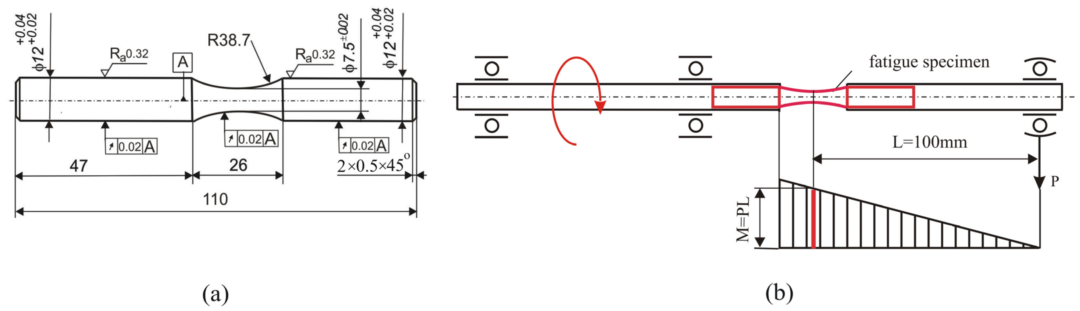
The cylindrical specimens were produced via dry hard turning and subsequent dry DB. Two-dimensional roughness parameters were measured using a Mitutoyo Surftest SJ-210 surface roughness tester (Kawasaki, Japan), and the average arithmetic values from the measurements on six equally spaced sample generatrixes were obtained. A ZHVμ Zwick/Roell microhardness tester (Ulm, Germany) was used to establish the surface microhardness (0.05 kgf loading and 10 s time holding). The final surface microhardness value was considered to be the median of the clustering of ten measurements. A Bruker D8 Advance X-ray diffractometer (Billerica, MA, USA) with a pinhole collimator with a primary beam measuring was used to measure the residual stresses. The characteristics of the residual stress X-ray measurement are shown in Table 1. The microstructure was observed via scanning electron microscopy (SEM, Zeiss Evo 10, Jena, Germany).

2.4. Fatigue Tests

Rotating bending fatigue tests were conducted on a UBM testing machine (Markkleeberg, Germany) at room temperature in air. The loading frequency was 50 Hz. Each specimen was tested to fatigue failure. Exceptions include the samples that reached 10 7 -cycle fatigue strength, after which the test was terminated. One specimen was used for each experimental point. The specimen geometry [41] is depicted in Figure 3a.
The fatigue test scheme is shown in Figure 3b. Five specimen groups were manufactured. The material for the first group of samples was in the as-received state and served as a reference condition (RC), while the remaining four groups of samples were heat treated. The first and second groups of specimens were turned and polished. Polishing was used to satisfy the surface roughness requirements of the fatigue specimens. The third, fourth, and fifth groups were diamond burnished (after fine turning) using burnishing forces of 50, 100, and 150 N, respectively.

3. Experimental Results

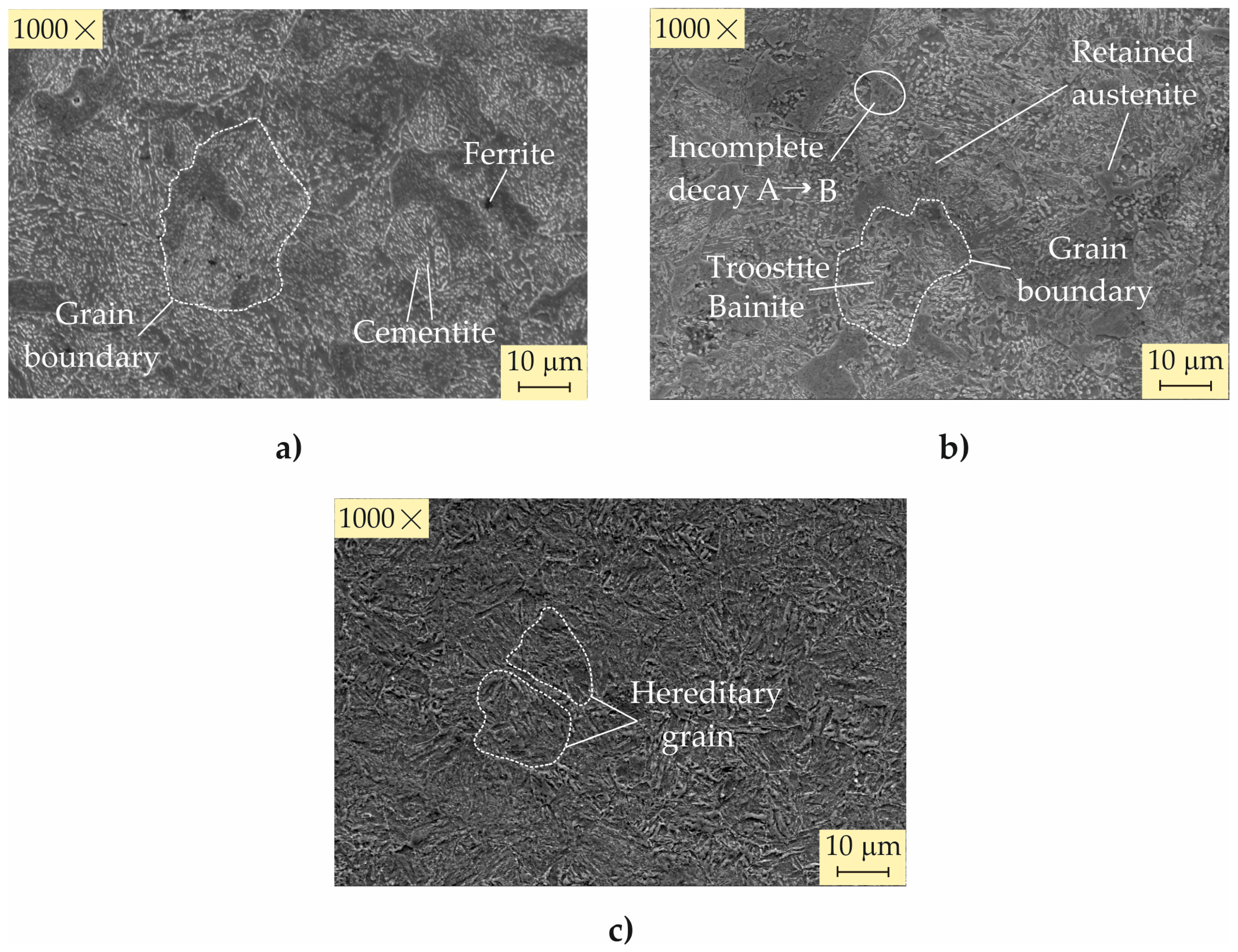
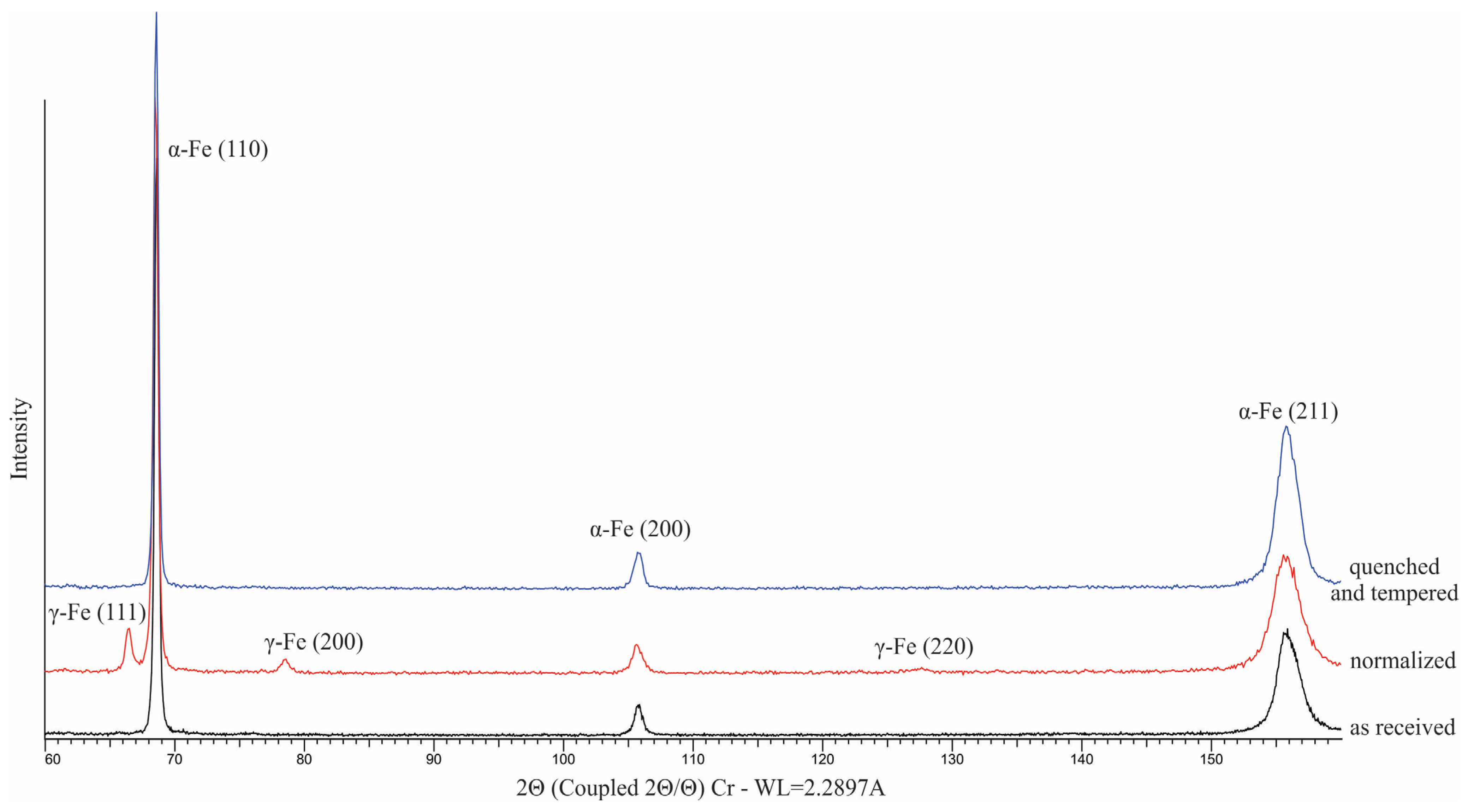
3.1. Characterization of the Material Used

The chemical composition of the 42CrMo4 steel used is shown in Table 2. The remaining chemical elements (complementing up to 100 wt%) are Co, Ti, and W.
The evolution of the main mechanical characteristics, a consequence of the heat treatments, is shown in Table 3. Normalization was conducted to improve the machinability by cutting and refining the structure. Compared to the as-received state, normalization significantly increases the static strength and hardness, reduces the elongation, and drastically reduces the impact toughness (by a factor of more than eight). The improvement (i.e., quenching and high-temperature tempering) in the normalized structure significantly increases the elastic area (the yield limit) and the elongation and slightly reduces the hardness. However, the improvement dramatically increases the impact toughness (by almost twice the amount compared to the as-received state and by a factor exceeding 14 compared to the normalized structure). It is this combination of properties of improved steel that make it a very suitable material for heavily loaded shafts and axles. Proof of this are the S-N curves (Figure 4), obtained for the as-received and improved states—the heat treatment increased the fatigue limit from 400 MPa to 740 MPa.
The microstructure of 42CrMo4 steel in the as-received state is ferrite–perlite (Figure 5a), as the steel is sub-eutectoid. The lighter areas in the photo are cementite (a component of the pearlite); the darker areas are ferrite.
A significant difference compared to the as-received state is observed after normalization (Figure 5b). The resulting structure is ferrite–sorbite, including approximately 10% retained austenite, established via DIFFRAC.DQuant V1.5 software [42]. The increased rate of cooling in air in the process of normalization (austenite decomposition, respectively) leads to the refinement of the structural components. As a result, the tensile strength and hardness are significantly increased: from 747 MPa to 1147 and from 234 HB to 324 HB, respectively.
The microstructure obtained after normalizing, quenching, and high-temperature tempering is shown in Figure 5c. The martensitic structure obtained after quenching undergoes changes in the tempering process. The presence of chromium and molybdenum greatly complicates martensite decomposition, reducing the rate of diffusion and increasing the temperature onset of martensite decomposition. This process is further complicated by the formation of complex carbides of the type FeCrMo3C, which have an elongated lamellar shape. The breakdown of martensite substantially reduces deformations and microstresses in the crystal structure and thus reduces residual internal macrostresses. The resulting structure has a lower free energy and a more stable state, providing higher plasticity (increased elongation of 12.9%, respectively) and significant impact toughness (see Table 3).
The presence of retained austenite in the normalized steel structure is confirmed by phase analysis (Figure 6). Bruker D8 Advance diffractometer (Billerica, MA, USA) and Bruker DIFFRAC.Dquant V1.5 and Bruker.Eva V.5.2 software were used. In addition to the standard diffraction maxima of the (110), (211), and (220) lines of α-Fe, diffraction maxima of the (111), (200), and (220) lines of γ-Fe were observed. The likely reason for the presence of retained austenite is the relatively high cooling rate combined with the action of chromium, molybdenum, and manganese. These elements slow the γ-Fe→α-Fe transformation, shifting it to lower temperatures and hindering the diffusive redistribution of carbon [43]. Carbon accumulates in front of the growing ferrite crystal, resulting in the formation of small regions of austenite with relatively high carbon content. This austenite has a stabilizing effect, and the γ→α transformation shifts to negative temperatures. In contrast, the presence of chromium and molybdenum hinders the diffusion of carbon from these enriched austenite zones, and some of it is retained in the form of residual austenite. This effect is enhanced by the increased cooling rate (in air) and the redistribution of Mo and Cr (which have different solubility in ferrite and cementite) in the conditions of hindered diffusion.

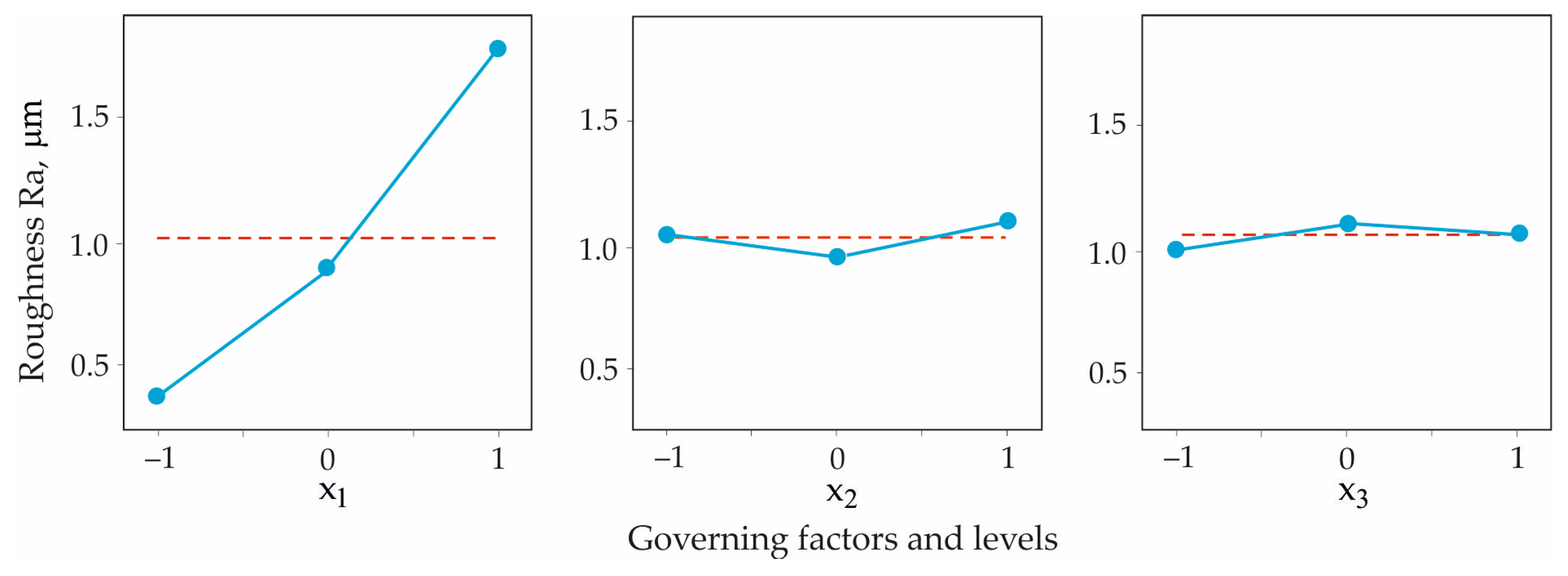
3.2. Optimization of Dry Turning
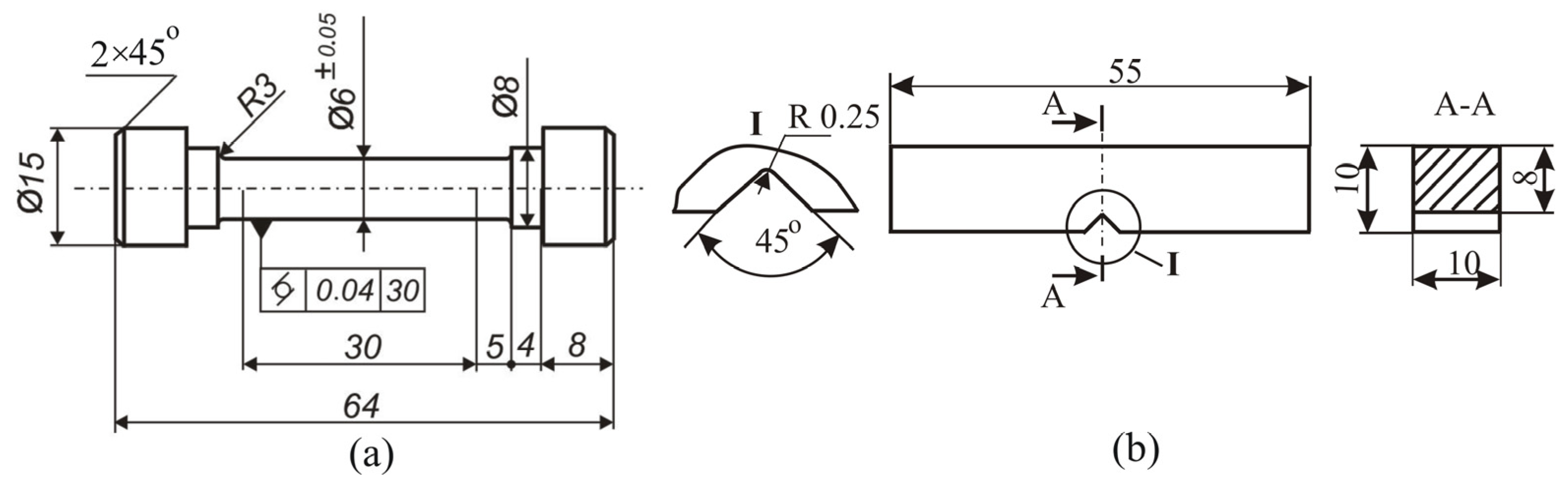
3.2.1. Specimens

The heat-treated specimens on which the SI characteristics are measured after dry turning are cylindrical with a nominal diameter of 24 mm and a length of 40 mm.

3.2.2. Governing Factors, Ective Functions

The selected governing factors of the hard turning process are feed rate f, cutting velocity v c , and cutting depth a c (Table 4). The dependence between the physical x ˜ i and the dimensionless x i variables is expressed as follows:
x i = x ˜ i x ˜ i , 0 x ˜ i , max x ˜ i , 0 .
where x ˜ i , 0 and x ˜ i , max are the average and maximum values of the physical variable, respectively.
The objective function Y is the roughness parameter Ra. A planned experiment and a second-order optimal composition design were used (Table 5).

3.2.3. Results and Optimization

The experimental results obtained are shown in Table 5. Regression analyses were performed using the QStatLab v. 6.1.1.3 software [44]. Given the chosen experimental design, the approximating polynomials are of an order no higher than the second as follows:
Y X = b 0 + i = 1 3 b i x i + i = 1 2 j = i 1 3 b i j x i x j + i = 1 3 b i i x i 2
where X is the vector of the governing factors x i .
The polynomial coefficients are shown in Table 6. The probability of a coefficient being insignificant is p = 0.05. However, all coefficients are included in the models to minimize the residual (Yexp-Ymodel) (see Table 5). Statistical analysis of the regression models was performed using QStatlab. The critical values of Student’s T statistics, Fisher’s F statistics, the residual standard deviation (ResStDev), the coefficient of determination (R-sq), and the adjusted coefficient of determination (Radj-sq) were as follows: T = 2.77645, F = 5.99878, ResStDev = 0.091564, R-sq = 0.99361, and Radj-sq = 0.97924. The results and residuals shown in Table 5 confirm the model’s adequacy.
The dimensionless absolute values of the coefficients b i ,   i = 1 , 2 , 3 , in Equation (2) show the degree of influence on the objective function. The most significant factor is the feed rate ( x 1 ). The cutting velocity ( x 2 ) and cutting depth ( x 3 ) have the same weight, but their influence is approximately 22 times less than that of the feed rate. An analysis of variance (ANOVA) was performed using the QStatLab software. The main effects, depicted in Figure 7, confirm the conclusions drawn regarding the significance of the factors. The minimum roughness Ra was obtained when the feed rate and cutting depth were maintained at low levels and the cutting velocity was maintained at a medium level. The selected experimental design does not include such a combination of values of the governing factors. It is possible that an intermediate level of x 2 could achieve the minimum of Ra. Using QStatLab [44] and a non-dominated sorting genetic algorithm [45], the minimum value of the Ra model and the corresponding values of the governing factors ensuring this minimum were found to be min Y R a = 0.1703   μ m , x 1 * = 1 , x 2 * = 0.4019 , and x 3 * = 1 . By means of (2), after inverse transformation of the variables, the following optimal values of the physical governing factors were obtained: a feed rate of 0.05 mm/rev, cutting velocity of 145 m/min, and cutting depth of 0.1 mm. These values of the governing factors are used further in the fine turning process.
To verify these results experimentally, 10 cylindrical specimens with a length of 60 mm and a diameter of 24 mm were subjected to fine turning. The measured values of the Ra roughness parameter varied within the range of 0.185–0.207 μm. The arithmetic mean value was 0.196 μm, which is less than the minimum value (0.208 μm) of Ra from the experimental plan (Table 5).

3.3. SI Characteristics After Dry Turning and Subsequent Dry DB
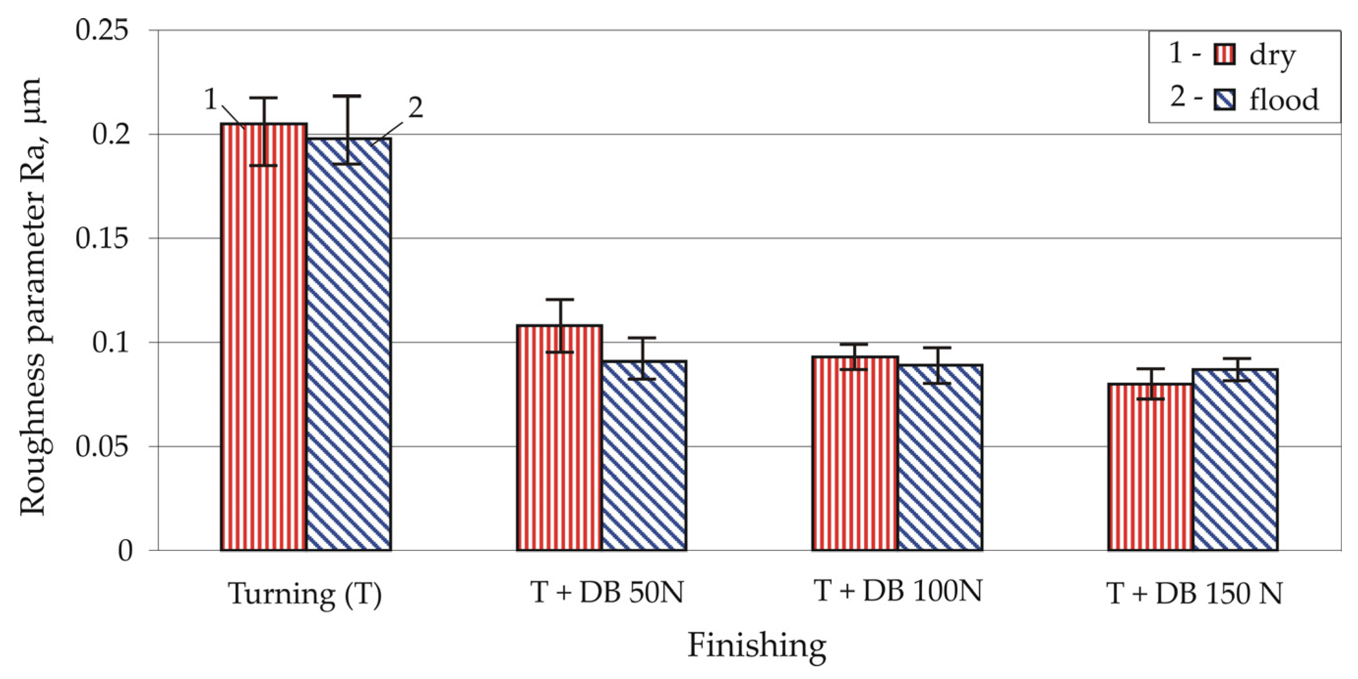
3.3.1. Roughness

The effects of different types of finishing on the height integral roughness parameter Ra and shape roughness parameters skewness and kurtosis are shown in Figure 8 and Figure 9. DB significantly reduces the height parameter Ra (leading to a mirror-like surface) and increases the skewness and kurtosis as algebraic numbers. These beneficial effects are enhanced with increasing burnishing force.

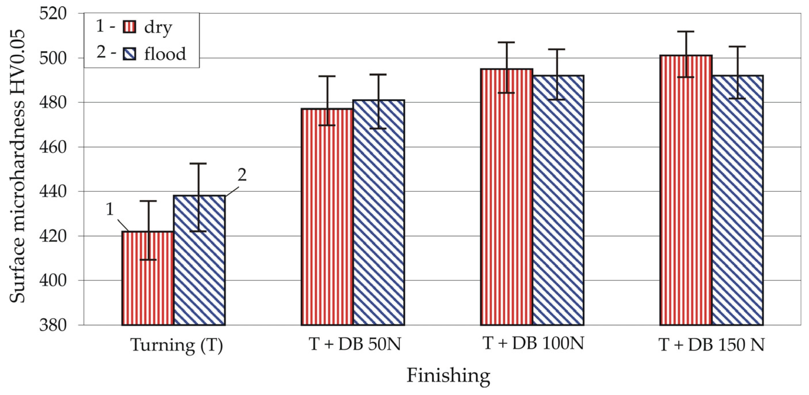
3.3.2. Surface Microhardness

Figure 10 shows the effects of DB, conducted with different values of the burnishing force, on the surface microhardness. As might be expected, DB (even when conducted as a smoothing process, i.e., with small burnishing forces) significantly increases the surface microhardness compared to turning.

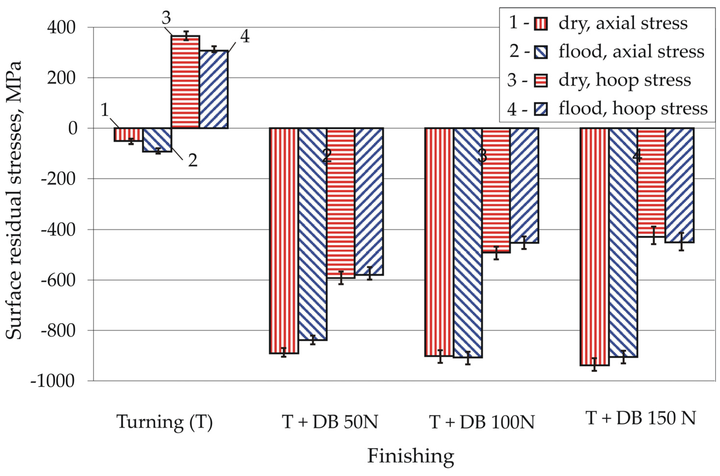
3.3.3. Residual Stresses

The surface residual axial and hoop stresses, introduced by different types of finishing, are depicted in Figure 11. The turning introduces insignificant compressive axial stresses and significant tensile hoop stresses in the surface layer. However, subsequent DB dramatically improves the SI by transforming the residual axial and hoop stresses into compressive stresses of significant magnitude (up to −937 MPa for axial stresses and up to −592 MPa for hoop stresses).
Figure 12 shows the residual axial stress distribution depending on the finishing. Dry turning introduces insignificant residual compressive stresses to a depth of up to 0.08 mm. All three dry DB processes (performed with 50, 100, and 150 N, respectively) introduce maximum residual stresses at the surface (−890.9 MPa, −902.6 MPa, and −937.4 MPa, respectively). The depths of the compressive zones are 0.235 mm, 0.260 mm, and 0.375 mm, respectively.

3.4. Fatigue Behavior

All tests were conducted in high-cycle ( 10 3 N 10 6 cycles) and mega-cycle ( N > 10 6 cycles) fatigue fields. The maximum amplitude of the bending stress (940 MPa) was less than the yield strength of the heat-treated material (967 MPa). The effects of dry turning and combined processes, in which DB was conducted using forces of 50, 100, and 150 N, on the fatigue behavior are illustrated in Figure 13. All three combined processes increased fatigue strength in the high-cycle fatigue field (from 10 3 to 10 6 cycles) compared to turning, and the fatigue life increased by up to 10 times. Up to approximately 400,000 cycles, diamond-burnished specimens burnished with a force of 150 N exhibited the highest fatigue strength. Beyond approximately 400,000 cycles, the fatigue strength of these specimens decreases sharply compared to that of the other two groups of diamond-burnished specimens. However, in the mega-cycle fatigue field (more than 10 6 cycles), only diamond burnishing with a 50 N burnishing force increased the fatigue limit compared to turning from 740 MPa to 760 MPa, i.e., by 2.7%, and the fatigue life increased by a factor of more than 70. With increasing burnishing force, this positive effect in the mega-cycle region decreased, and a decrease in the fatigue limit was observed compared to the result obtained by turning.

4. Discussion

4.1. Effects of Sustainable Combined Process on SI

The use of cutting fluid in turning and DB has the ultimate goal of improving SI. However, the use of cutting fluid and sustainable processing are incompatible concepts, as one excludes the other. Figure 8, Figure 9, Figure 10 and Figure 11 show comparisons between the SI characteristics obtained by sustainable and conventional (using cutting fluid) processes. The conventional processes were implemented with the same magnitudes of the governing factors as the corresponding sustainable processes but under flood lubrication conditions.
The conventional turning provides an average roughness of 0.198 μm versus 0.205 μm obtained by dry turning. (Figure 8). The difference is negligible and of no practical significance. The achieved average roughness Ra = 0.205 μm via dry turning is fully consistent with the result achieved in [18], where Ra = 0.2 μm was achieved.
With increasing burnishing force in the dry DB process, the average roughness Ra (Figure 8) significantly decreased, and at 150 N, it was 0.080 μm versus the 0.087 μm obtained with DB under flood lubrication conditions. However, dry DB with a 50-N burnishing force achieved an average roughness of 0.108 μm, versus 0.091 μm achieved with conventional DB. It can be concluded that according to the Ra criterion, the advantage of conventional DB is negligible. The higher rate of decrease in the average roughness Ra depending on the burnishing force used in the dry DB process is attributable to higher friction forces causing greater equivalent plastic deformation.
Both turning processes provide skewness around zero and kurtosis less than three. (Figure 9). The six DB processes lead to positive skewness (except for DB implemented under flood conditions with a 50-N burnishing force) and kurtosis greater than three. With increasing burnishing force, the shape roughness parameters increase, with the rate of increase being greater for the conventional DB. The established trend of increasing the skewness with increasing burnishing force occurs for two reasons: (1) the surface equivalent plastic deformation generated by DB leads to greater smoothing of the sharp peaks and thus reduces the deep valleys and (2) the optimized turning process, in addition to leading to a low average roughness Ra (0.205 μm), results in skewness close to zero. According to Zabala et al. [46], dry DB with 50-N burnishing force has an advantage over the corresponding conventional DB in terms of fatigue behavior because of the positive skewness, while in terms of wear resistance under the boundary lubrication conditions [47], conventional DB has the advantage (negative skewness is characterized by deep valleys that retain oil but are also natural stress concentrators).
The six DB processes significantly increase the surface microhardness compared to turning processes (Figure 10), where the microhardness increases with increasing burnishing force. This trend is more pronounced for dry DB. In addition, dry DB processes lead to greater microhardness than conventional DB processes, with the exception of the process implemented with a burnishing force of 50 N. The deformation process at DB generates two effects: mechanical and thermal. The mechanical effect is expressed in an increased density of dislocations and structure transformation, i.e., in strain hardening. The thermal effect is a consequence of the heat generated by friction and plastic deformation and leads to temperature deformations that are unrelated to the strain hardening. In addition, these thermal deformations are the cause of the so-called softening effect. The ratio between the magnitudes of the two effects (mechanical and thermal) determines the magnitudes of the physical-mechanical characteristics of SI. The fact that in dry DB microhardness increases with increasing burnishing force, means that the mechanical effect prevailed over the thermal one.
Dry DB processes introduce larger residual surface compressive stresses compared to conventional DB processes (Figure 11), with the exception of the hoop stress introduced via a burnishing force of 150 N. In both types (dry and conventional) DB processes, with increasing burnishing force, axial residual stresses increase in absolute value, while circumferential residual stresses decrease. Surface microhardness and residual stresses have a common physical basis: the equivalent plastic deformation and structure transformation in SL. Therefore, the observed trend for microhardness is also valid for the surface residual stresses. Overall, the surface microhardness and residual stresses are slightly lower than those achieved in [18] because of the different heat treatment applied to the 42CrMo4 steel. In [18], after quenching, low-temperature tempering (at 240 °C for 2 h) was performed, which suppresses the decomposition of the solid solution and provides higher hardness (54 HRC). However, our objects are shafts and axles, of which high impact toughness is required. Therefore, we performed high-temperature tempering. The resulting hardness was lower, but the impact toughness was significantly higher.
Figure 12 shows that with increasing burnishing force, both the surface residual axial compressive stresses and the depth of the compression zone increase because of the increased equivalent plastic deformation of the surface and nearby subsurface layers. However, at the same time, the dislocation density in these layers also increases. It should be noted that the measured stresses are actually macrostresses, while the introduced microdefects are caused by an excessive increase in second- and third-order microstresses.
In general, comparisons between dry and conventional DB by SI characteristics criterion show a slight advantage for dry (sustainable) DB. Therefore, the developed combined process, including successive dry hard turning and dry DB, besides being sustainable, provides higher-quality SI compared to successively applied conventional turning and DB.

4.2. Effects of Sustainable Combined Process on Fatigue Behavior

According to [48], the cause of microcrack nucleation in a metal component subjected to cyclic external loading is a local defect (focus) in the material at the nano-level. After N11 cycles, a new configuration of dislocations occurs around this focus, resulting in the formation of a multitude of microcracks. After another N12 cycle these microcracks merge into one fatigue macrocrack, requiring a total of N1 = N11 + N12 cycles. The third stage of fatigue failure is fatigue macrocrack growth, which requires another N2 cycle. Thus, the total number of cycles to fatigue failure is N = N1 + N2 (Figure 14a). Figure 14b illustrates the process of obtaining the final experimental S-N curve.
The material of the four groups of samples (see Figure 13) was the same: heat-treated 42CrMo4 steel. The three groups of diamond-burnished specimens differ from the turned specimens only in the presence of modified surface layers up to a few micrometers thick. Thus, the group of only turned specimens serves as the RC. To isolate and evaluate the influence of DB interventions on the fatigue behavior of heat-treated 42CrMo4 steel, the S-N curves in Figure 13 are transformed into straight lines in a double-logarithmic coordinate system after taking the logarithm of the Basquin equation [49], which has the following form: S = CNb, where S is the stress amplitude, N is the number of cycles to failure, b is the fatigue strength index, and C is the stress for a single repetition (ultimate bending stress Su). The fatigue strength index b was obtained from the equation b = (1/6)log(Se/Su), where Se is the fatigue limit and Su is the ultimate bending stress. Three-point bending tests were conducted using a Zwick/Roell Vibrophore 100 testing machine and cylindrical specimens with diameters of 7.5 mm and lengths of 100 mm to determine the ultimate bending stress. Four groups of specimens, each containing three specimens, were tested: turned only and diamond burnished with burnishing forces of 50, 100, and 150 N. Each ultimate bending stress was obtained as the arithmetic mean of three tests.
Basquin’s equations for the four groups were obtained as follows:
S = 2368 N 0.0842 RC ,
S = 2408 N 0.0835 DBed_50 ,
S = 2369 N 0.0847 DBed_100 ,
S = 2369 N 0.0862 DBed_150 ,
where RC is turned only, DBed_50 is diamond burnished with 50-N burnishing force, DBed_100 is diamond burnished with 100-N burnishing force, and DBed_150 is diamond burnished with 150-N burnishing force.
Based on the Basquin equations obtained, the following hypothesis was developed for the effect of DB on the fatigue failure of diamond-burnished specimens processed with burnishing forces of different magnitudes.
The fatigue strength index b of the DBed_50 specimens, Equation (4), differs insignificantly compared to RC, Equation (3). Therefore, the fatigue crack growth resistance of DBed_50 specimens has not changed significantly. Thus, the higher fatigue limit of these specimens is due to increased fatigue crack nucleation resistance because of the thin modified surface layer. With increasing burnishing force (100 and 150 N), the fatigue index b increases in absolute value (see Equations (5) and (6)). According to [50,51], an increase in fatigue crack growth resistance should be expected. However, the bulk material of all groups of specimens was the same and by itself cannot change its fatigue crack growth resistance. The fatigue limits of the DBed_100 and DBed_150 specimens were lower than the fatigue limit of RC, which means that the fatigue crack nucleation resistance of these specimens was reduced. This in turn suggests the rapid formation of multiple fatigue microcracks due to the changed configuration of the dislocations. The most vulnerable place for the occurrence of these multiple microcracks and their merging into a common fatigue macrocrack is the boundary between the bulk material and the modified surface layer. Because of its thinness, this layer is characterized by large gradients in its properties. Since the bending stresses throughout the thickness of the modified layer are practically the same (including at the interface between the modified layer and the bulk material), favorable conditions exist for the development and formation of fatigue macrocracks immediately below the modified layer. Under the action of continued cyclic loading, this crack progresses to a greater depth, reducing the net cross-section of the specimen. After the destruction of the modified layer above this crack (which immediately turns it into an open crack), the speed of the crack growth increases, and very soon, the specimen collapses.
A fractographic analysis was conducted to prove the above hypothesis. According to Figure 13 and the Basquin equations obtained, DBed_100 specimens occupy an intermediate position between DBed_50 and DBed_150 specimens. For this reason, one representative from each of the three groups of samples (excluding DBed_100) was subjected to fractographic analysis. Specimens were fractured at a stress amplitude of 840 MPa and the following number of cycles: RC—15,000; DBed_50—38,000; and DB_150—124,000. The fracture surfaces of these specimens are presented in Figure 15. Based on the experimental results for the surface microhardness (Figure 10) and the residual stresses (Figure 11 and Figure 12), it can be assumed that the thickness of the affected layer increases with increasing burnishing force (see Figure 15a). The fracture surfaces of the diamond-burnished specimens are very similar to each other and differ drastically from the fracture surface of the turned specimen (Figure 15b). In the turned specimen, two oppositely located crack propagation zones are clearly distinguishable. Because of the absence of a significantly affected surface layer, the microcrack nucleation and macrocrack formation are located in the surface layer, as can be seen in Figure 16.
Because of the very thin affected layer in the DB_50 specimen, microcrack nucleation and macrocrack formation practically start from the surface layer, as shown in Figure 17. This confirms the hypothesis made above that DB implemented with a minimal force (50 N) increases the crack nucleation resistance, but the macrocrack growth rate is the same as in the turned specimen (i.e., RC). Thus, the Basquin lines for the RC and DBed_50 specimens are almost parallel. The SEM image in Figure 17 indicates two fatigue failure mechanisms. Near the surface, a transcrystalline mechanism is observed, while at a greater depth, an intercrystalline failure mechanism predominates.
Figure 18 clearly shows the presence of a modified layer with a thickness of several micrometers formed in the DBed_150 specimen. The fatigue microcrack nucleation and macrocrack formation zones are located immediately below this layer, at the boundary with the bulk material.
The fatigue test results and the fractographical analyses clearly show that for heat-treated 42CrMo4 steel axles and shafts, DB at a low force level (50 N) should be employed for finishing to maximize the fatigue limit while ensuring high SI quality.

5. Conclusions

The research produced a sustainable combined process involving sequentially optimized dry hard turning and dry DB that provides high-quality SI and maximizes the fatigue limit of heat-treated 42CrMo4 steel shafts and axles. A holistic approach was used to achieve maximum synergy between the two sequential processes in the combined process. The two-stage study involved the optimization of dry hard turning under an Ra roughness criterion and the selection of a suitable dry DB from among three alternative DB processes, implemented with burnishing forces of 50, 100, and 150 N. The key findings are as follows:
  • Using the non-dominated sorting genetic algorithm II, the minimum value of the model average roughness Ra (due to turning) and the corresponding values of the governing factors were found as follows: minRa = 0.17 μm, feed rate of 0.05 mm/rev, cutting velocity of 145 m/min, and cutting depth of 0.1 mm.
  • Based on a comparison with sequentially applied turning and DB (under flood lubrication conditions), the experimental results show that the sustainable combined process developed in this study provides SI of a higher quality.
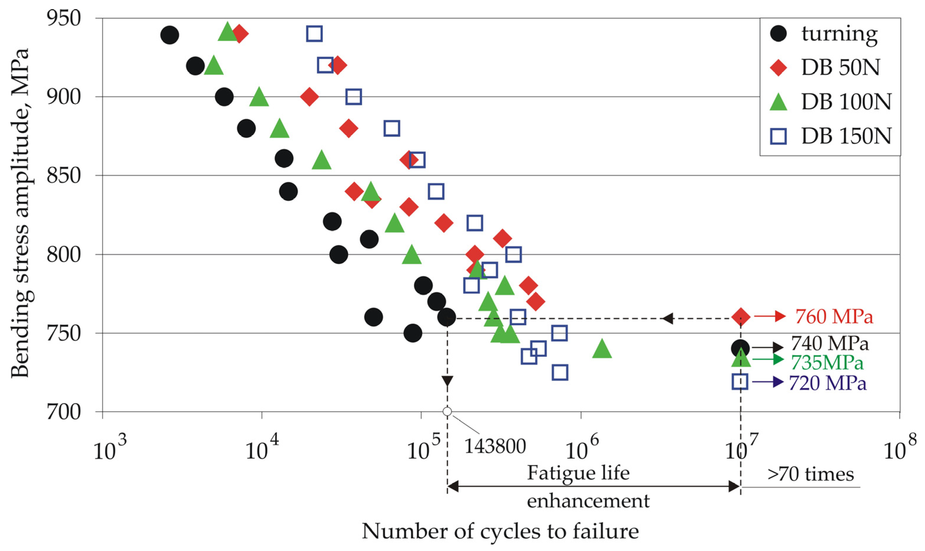
  • With increasing burnishing force, the average roughness Ra decreases, the microhardness increases, and the surface axial residual stresses increase in absolute value. However, the fatigue limit decreases, and at burnishing forces of 100 and 150 N, the fatigue limit is smaller than obtained via the previous turning.
  • The sustainable combined process (with a diamond burnishing force of 50 N) developed in this study is effective for heat-treated 42CrMo4 steel shafts and axles, which require high fatigue strength in the mega-cycle fatigue field.
  • The fatigue test results show that the highest burnishing force (150 N) resulted in the greatest fatigue strength in the first half of the high-cycle fatigue field. This finding reveals the potential of the sustainable combined process for future research when the requirements for the metal component are for high fatigue strength in the low-cycle fatigue field.

Author Contributions

Conceptualization, J.M. and G.D.; methodology, J.M. and G.D.; software, J.M., G.D., A.A., V.D., and M.I.; validation, J.M., and G.D.; formal analysis, J.M. and G.D.; investigation, A.A., V.D., K.A., J.M., G.D., and M.I.; resources, J.M., G.D. and K.A.; data curation, J.M., G.D., and K.A.; writing—original draft preparation, J.M. and G.D.; writing—review and editing, J.M. and G.D.; visualization, J.M., G.D., A.A., V.D., and M.I.; supervision, G.D.; project administration, J.M. and G.D.; funding acquisition, J.M. and G.D. All authors have read and agreed to the published version of the manuscript.

Funding

This research was funded by the European Regional Development Fund under the Operational Program “Scientific Research, Innovation and Digitization for Smart Transformation 2021–2027”, Project CoC “SmartMechatronics, Eco- and Energy Saving Systems and Technologies”, BG16RFPR002-1.014-0005.

Data Availability Statement

The original contributions presented in the study are included in the article, further inquiries can be directed to the corresponding author.

Conflicts of Interest

The authors declare no conflicts of interest.

Abbreviations

ANOVAAnalysis of variance
CFCutting fluid
DBDiamond burnishing
DRDeep rolling
MQLMinimum lubrication quantity
RCReference condition
SCWSurface cold working
SISurface integrity
SLsSurface layers

References

  1. Molotnikov, V.; Molotnikova, A. Shaft and Axle. In Theoretical and Applied Mechanics; Springer: Cham, Switzerland, 2023. [Google Scholar] [CrossRef]
  2. Balevski, A.T. Metal Science; Technika: Sofia, Bulgaria, 1988. (In Bulgarian) [Google Scholar]
  3. Hull, E.H.; Nerad, A.J. Irregular Diamond Burnishing Tool. U.S. Patent 2,966,722, 3 January 1961. [Google Scholar]
  4. Maximov, J.T.; Duncheva, G.V.; Anchev, A.P.; Ichkova, M.D. Slide burnishing—Review and prospects. Int. J. Adv. Manuf. Technol. 2019, 104, 785–801. [Google Scholar] [CrossRef]
  5. Ecoroll Catalogue. Tools and Solutions for Metal Surface Improvement; Ecoroll Corporation Tool Technology: Milford, OH, USA, 2006. [Google Scholar]
  6. Korzynski, M. Modeling and experimental validation of the force-surface roughness relation for smoothing burnishing with a spherical tool. Int. J. Mach. Tools Manuf. 2007, 47, 1956–1964. [Google Scholar] [CrossRef]
  7. Luo, Y.; Li, G.; Ao, N.; Qi, C.; Wu, Y.; Zhang, G.; Wu, S. Effect of ultrasonic rolled material layer on the corrosion fatigue resistance of railway axle EA4T alloy steel. Eng. Fail. Anal. 2024, 157, 107895. [Google Scholar] [CrossRef]
  8. Pertoll, T.; Buzzi, C.; Leitner, M.; Boronkai, L. Application of local fatigue strength approach to assess and optimize the impact of deep rolling on the fatigue performance of railway axles. Int. J. Fatigue 2024, 185, 108335. [Google Scholar] [CrossRef]
  9. Abrão, A.M.; Denkena, B.; Köhler, J.; Breidenstein, B.; Mörke, T.; Rodrigues, P.S.M. The influence of heat treatment and deep rolling on the mechanical properties and integrity of AISI 1060 steel. J. Mater. Process. Technol. 2014, 214, 3020–3030. [Google Scholar] [CrossRef]
  10. Regazzi, D.; Cantini, S.; Cervello, S.; Conte, A.L.; Foletti, S.; Pourheidar, A.; Beretta, S. Improving fatigue resistance of railway axles by cold rolling: Process optimisation and new experimental evidences. Int. J. Fatigue 2020, 137, 105603. [Google Scholar] [CrossRef]
  11. Swirad, S.; Pawlus, P. The effect of ball burnishing on tribological performance of 42CrMo4 steel under dry sliding conditions. Materials 2020, 13, 2127. [Google Scholar] [CrossRef]
  12. Dzierwa, A.; Markopoulos, A.P. Influence of Ball-Burnishing Process on Surface Topography Parameters and Tribological Properties of Hardened Steel. Machines 2019, 7, 11. [Google Scholar] [CrossRef]
  13. Maximov, J.T.; Duncheva, G.V.; Anchev, A.P.; Dunchev, V.P. Slide burnishing versus deep rolling—A comparative analysis. Int. J. Adv. Manuf. Technol. 2020, 110, 1923–1939. [Google Scholar] [CrossRef]
  14. Swirad, S. The surface texture analysis after sliding burnishing with cylindrical elements. Wear 2011, 271, 576–581. [Google Scholar] [CrossRef]
  15. Korzynski, M.; Lubas, J.; Swirad, S.; Dudek, K. Surface layer characteristics due to slide diamond burnishing with a cylindrical-ended tool. J. Mater. Process. Technol. 2011, 211, 84–94. [Google Scholar] [CrossRef]
  16. Kluz, R.; Antosz, K.; Trzepiecinski, T.; Bucior, M. Modelling the influence of slide burnishing parameters on the surface roughness of shafts made of 42CrMo4 heat-treatable steel. Materials 2021, 14, 1175. [Google Scholar] [CrossRef]
  17. Kluz, R.; Trzepiecinski, T.; Bucior, M.; Antosz, K. Modelling of the effect of slide burnishing on the surface roughness of 42CrMo4 steel shafts. In Advances in Design, Simulation and Manufacturing IV; Lecture Notes in Mechanical Engineering; Springer: Cham, Switzerland, 2021; pp. 415–424. [Google Scholar]
  18. Zaghal, J.; Molnar, V.; Benke, M. Improving surface integrity by optimizing slide diamond burnishing parameters after hard turning of 42CrMo4 steel. Int. J. Adv. Manuf. Technol. 2023, 128, 2087–2103. [Google Scholar] [CrossRef]
  19. Sirin, S.Y.; Sirin, K.; Kaluc, E. Effect of the ion nitriding surface hardening process on fatigue behavior of AISI 4340 steel. Mater. Charact. 2008, 59, 351–358. [Google Scholar] [CrossRef]
  20. Terres, M.A.; Laalai, N.; Sidhom, H. Effect of nitriding and shot-peening on the fatigue behavior of 42CrMo4 steel: Experimental analysis and predictive approach. Mater. Des. 2012, 35, 741–748. [Google Scholar] [CrossRef]
  21. Adler, D.P.; Hii, W.W.-S.; Michalek, D.J.; Sutherland, J.W. Examining the role of cutting fluids in machining and efforts to address associated environmental/health concerns. Mach. Sci. Technol. 2006, 10, 23–58. [Google Scholar] [CrossRef]
  22. Elsadek, A.A. Investigating the performance of the pressurized injection technique in the turning process. Int. J. Adv. Manuf. Technol. 2024, 134, 5697–5715. [Google Scholar] [CrossRef]
  23. Klocke, F.; Eisenblätter, G. Dry cutting. CIRP Ann. 1997, 46, 519–526. [Google Scholar] [CrossRef]
  24. Narutaki, N.; Yamane, Y.; Tashima, S.; Kuroki, H. A new advanced ceramic for dry machining. CIRP Ann. 1997, 46, 43–48. [Google Scholar] [CrossRef]
  25. Shokrani, A.; Dhokia, V.; Newman, S.T. Environmentally conscious machining of difficult-to-machine materials with regard to cutting fluids. Int. J. Mach. Tools Manuf. 2012, 57, 83–101. [Google Scholar] [CrossRef]
  26. Debnath, S.; Reddy, M.M.; Yi, Q.S. Environmental friendly cutting fluids and cooling techniques in machining: A review. J. Clean. Prod. 2014, 83, 33–47. [Google Scholar] [CrossRef]
  27. Shokrani, A.; Dhokia, V.; Newman, S.T.; Imani-Asrai, R. An initial study of the effect of using liquid nitrogen coolant on the surface roughness of inconel 718 nickel-based alloy in CNC milling. Procedia Cirp 2012, 3, 121–125. [Google Scholar] [CrossRef]
  28. Bennett, E.O. Water based cutting fluids and human health. Tribol. Int. 1983, 16, 133–136. [Google Scholar] [CrossRef]
  29. Elsner, P.; Wilhelm, D.; Maibach, H.I. Irritant Contact Dermatitis irritant contact dermatitis and aging. Contact Dermat. 1990, 23, 275. [Google Scholar] [CrossRef]
  30. Shashidhara, Y.M.; Jayaram, S.R. Vegetable oils as a potential cutting fluid—An evolution. Tribol. Int. 2010, 43, 1073–1081. [Google Scholar] [CrossRef]
  31. Clapp, R.W.; Jacobs, M.M.; Loechler, E.L. Environmental and occupational causes of cancer: New evidence 2005–2007. Rev. Environ. Health 2008, 23, 1–37. [Google Scholar] [CrossRef]
  32. Mackerer, C.R. Health effects of oil mists: A brief review. Toxicol. Ind. Health 1989, 5, 429–440. [Google Scholar] [CrossRef]
  33. Said, Z.; Gupta, M.; Hegab, H.; Arora, N.; Khan, A.M.; Jamil, M.; Bellos, E. A comprehensive review on minimum quantity lubrication (MQL) in machining processes using nano-cutting fluids. Int. J. Adv. Manuf. Technol. 2019, 105, 2057–2086. [Google Scholar] [CrossRef]
  34. Jawahir, I.S.; Attia, H.; Biermann, D.; Duflou, J.; Klocke, F.; Meyer, D.; Newman, S.T.; Pusavec, F.; Putz, M.; Rech, J.; et al. Cryogenic manufacturing processes. CIRP Ann. 2016, 65, 713–736. [Google Scholar] [CrossRef]
  35. Sachin, B.; Narendranath, S.; Chakradhar, D. Effect of cryogenic diamond burnishing on residual stress and microhardness of 17-4 PH stainless steel. Mater. Today Proc. 2018, 5, 18393–18399. [Google Scholar] [CrossRef]
  36. Maximov, J.T.; Duncheva, G.V.; Anchev, A.P.; Dunchev, V.P.; Anastasov, K.; Argirov, Y.B. Sustainable Diamond Burnishing of Chromium–Nickel Austenitic Stainless Steels: Effects on Surface Integrity and Fatigue Limit. Appl. Sci. 2024, 14, 9031. [Google Scholar] [CrossRef]
  37. Yu, X.; Wang, L. Effect of various parameters on the surface roughness of an aluminium alloy burnished with a spherical surfaced polycrystalline diamond tool. Int. J. Mach. Tools Manuf. 1999, 39, 459–469. [Google Scholar] [CrossRef]
  38. Kuznetsov, V.; Makarov, A.; Skorobogatov, A.; Skorinina, P.; Luchko, S.; Sirosh, V.; Chekan, N. Influence of normal force on smoothing and hardening of the surface layer of steel 03X16N15M3T1 during dry diamond smoothing with a spherical indenter. Met. Process. 2022, 24, 6–22. (In Russian) [Google Scholar]
  39. ISO 6892-1:2019; Metallic Materials—Tensile Testing—Part1: Method of Test at Room Temperature. ISO: Geneva, Switzerland, 2019.
  40. ISO 26843:2015; Metallic Materials—Measurement of Fracture Toughness at Impact Loading Rates Using Precracked Charpy-Type Test Pieces. ISO: Geneva, Switzerland, 2015.
  41. Bulgarian National Standard 5297:1983 Metals; Fatigue Test Methods. Standards Press of Bulgaria: Sofia, Bulgaria, 1983. (In Bulgarian)
  42. DIFFRAC.DQUANT. Quantitative Analysis from Calibration to Reporting; Bruker AXS GmbH: Karlsruhe, Germany, 2018. [Google Scholar]
  43. Rashkov, N.D. Heat Treatment of Steel; Technika: Sofia, Bulgaria, 1977. (In Bulgarian) [Google Scholar]
  44. Vuchkov, I.N.; Vuchkov, I.I. QStatLab Professional, version 6.1.1.3, Statistical Quality Control Software, User’s Manual. QStatLab: Sofia, Bulgaria, 2009.
  45. Deb, K.; Pratap, A.; Agarwal, S.; Meyarivan, T. A Fast and Elitist Multiobjective Genetic Algorithm: NSGA-II. IEEE Trans. Evol. Comput. 2002, 6, 182–197. [Google Scholar] [CrossRef]
  46. Zabala, A.; Blunt, L.; Tato, W.; Aginagalde, A.; Gomez, X.; Llavori, I. The use of areal surface topography characterisation in relation to fatigue performance. MATEC Web Conf. 2018, 165, 14013. [Google Scholar] [CrossRef]
  47. Sedlacek, M.; Podgornik, B.; Vizintin, J. Correlation between standard roughness parameters skewness and kurtosis and tribological behaviour of contact surface. Tribol. Int. 2012, 48, 102–112. [Google Scholar] [CrossRef]
  48. Georgiev, M.; Mejova, N. Resistance of Metals under Cyclic Loading; Bulvest: Sofia, Bulgaria, 2000. (In Bulgarian) [Google Scholar]
  49. Basquin, O.H. The exponential law of endurance tests. In Proceedings of the Thirteenth Annual Meeting of American Society for Testing Materials, Atlantic City, NJ, USA, 28 June–2 July 1910; Volume X, pp. 625–630. [Google Scholar]
  50. Men, F.; Zhang, M. Fatigue properties and fatigue strength prediction of 439 ferritic stainless steel. Eng. Fail. Anal. 2023, 145, 107054. [Google Scholar] [CrossRef]
  51. Stephens, R.I.; Fatemi, A.; Stephens, R.R.; Fuchs, H.O. Metal Fatigue in Engineering; John Wiley & Sons Inc.: New York, NY, USA, 2001. [Google Scholar]
Figure 1. Specimen geometry: (a) tensile test; (b) impact toughness test.
Metals 15 00755 g001
Figure 2. DB device.
Metals 15 00755 g002
Figure 3. Fatigue specimen geometry (a) and fatigue test scheme (b).
Metals 15 00755 g003
Figure 4. S-N curves of the steel in as-received and heat-treated states.
Metals 15 00755 g004
Figure 5. Evolution of the microstructure as a result of heat treatment: (a) as-received; (b) normalized; (c) normalized, quenched, and tempered.
Metals 15 00755 g005
Figure 6. Phase analysis results.
Metals 15 00755 g006
Figure 7. ANOVA main effects.
Metals 15 00755 g007
Figure 8. Roughness parameter Ra depending on the finishing.
Metals 15 00755 g008
Figure 9. Roughness parameters skewness and kurtosis depending on the finishing.
Metals 15 00755 g009
Figure 10. Surface microhardness HV0.05 depending on the finishing.
Metals 15 00755 g010
Figure 11. Surface residual stresses depending on the finishing.
Metals 15 00755 g011
Figure 12. Residual axial stress distribution depends on the finishing.
Metals 15 00755 g012
Figure 13. S-N curves.
Metals 15 00755 g013
Figure 14. Fatigue failure: (a) main stages; (b) final S-N curve formation.
Metals 15 00755 g014
Figure 15. Selected fatigue specimens (stress amplitude of 840 MPa; number of cycles to failure: turned specimen—15,000, DB with 50 N—38,000, DB wit 150 N—124,000): (a) schematic representation of the critical cross-section; (b) fracture surfaces.
Metals 15 00755 g015
Figure 16. Fracture surfaces of the turned fatigue specimen (stress amplitude of 840 MPa, number of cycles to failure: 15,000).
Metals 15 00755 g016
Figure 17. Fracture surfaces of the diamond-burnished fatigue specimen with burnishing force of 50 N (stress amplitude of 840 MPa, number of cycles to failure: 38,000).
Metals 15 00755 g017
Figure 18. Fracture surfaces of the diamond-burnished fatigue specimen with burnishing force of 150 N (stress amplitude of 840 MPa, number of cycles to failure: 124,000).
Metals 15 00755 g018
Table 1. Characteristics of the X-ray measurement of residual stresses in 42CrMo4 steel.
Measuring DeviceBruker D8 Advance Diffractometer
X-ray tubeLong focus Cr–Kα
Crystallographic planeFe(α)—(211)
Diffraction angle (2θ)146.08° (152–160°)
Measuring methodOffset coupled TwoTheta/Theta (sin2ψ method)
Scan modeContinuous PSD fast
X-ray detectorSSD160-2 (1D scanning)
Collimator spot sizeStandard Φ1.0 mm
Measurement time for single scanApprox. 30 s
Elastic constant s1 1.271 × 10 6
Elastic constant 1/2s2 5.811 × 10 6
Voltage30 kV
Current40 mA
Step size0.5°
Time for step1 s
Table 2. Chemical composition (in wt%) of the 42CrMo4 steel used.
FeCSiMnPSCrMoNiAlNbCuVPb
97.10.4630.1930.8420.00820.00631.070.1830.00660.02270.00620.03520.00630.0074
Table 3. Main mechanical characteristics of the tested 42CrMo4 steel.
Material StateYield Limit,
MPa
Tensile Strength,
MPa
Elongation,
%
Hardness,
HB
Impact Toughness,
J / c m 2
A-R 708 + 2 1 747 ± 1 10.9 + 0.1 0.2 233.7 + 0.9 1.2 64 ± 2
N 926 + 15 16 1148 + 6 8 8.8 + 0.2 0.1 323.5 + 2.7 4.6 7.6 ± 0.6
N + Q + T 967 + 14 8 1046 ± 8 12.9 ± 0.1 307.4 + 5.2 4.7 112 + 3 2
Note: A-R—as-received; N—normalized; N + Q + T—normalized, quenched, and tempered.
Table 4. Governing factors and their levels.
Governing FactorsLevels
Natural ,   x ˜ i Coded ,   x i
Feed rate f   [ m m / r e v ] x ˜ 1 0.050.1250.2 x 1 −101
Cutting velocity v c   [ m / min ] x ˜ 2 130155180 x 2 −101
Depth of cutting a c   [ m m ] x ˜ 3 0.10.551.0 x 3 −101
Table 5. Experimental design and results.
No. x 1 x 2 x 3 Ra, μm
ExperimentModelResidual
1−1−1−10.20800.18850.0195
21−1−11.81901.8776−0.0586
3−11−10.34500.3604−0.0154
411−11.92701.86050.0665
5−1−110.39600.4625−0.0665
61−111.78501.76960.0154
7−1110.65900.60040.0586
81111.69901.7185−0.0195
9−1000.46200.45820.0038
101001.85801.8618−0.0038
110−101.12101.03080.0902
120101.00101.0912−0.0902
1300−10.74700.7590−0.0120
140010.83700.82500.0120
Table 6. Regression coefficients.
b 0 ( k ) b 1 ( k ) b 2 ( k ) b 3 ( k ) b 11 ( k ) b 22 ( k ) b 33 ( k ) b 12 ( k ) b 23 ( k ) b 13 ( k )
0.9541250.70180.03020.03300.2058750.106875−0.162125−0.04725−0.0085−0.0955
Disclaimer/Publisher’s Note: The statements, opinions and data contained in all publications are solely those of the individual author(s) and contributor(s) and not of MDPI and/or the editor(s). MDPI and/or the editor(s) disclaim responsibility for any injury to people or property resulting from any ideas, methods, instructions or products referred to in the content.

