

Synthesis of a Vanadium-Substituted Fe–Ti-Based Ternary Alloy via Mechanical Alloying, Compacting, and Post-Annealing

 and
and
Abstract
1. Introduction
2. Materials and Methods
3. Results and Discussion
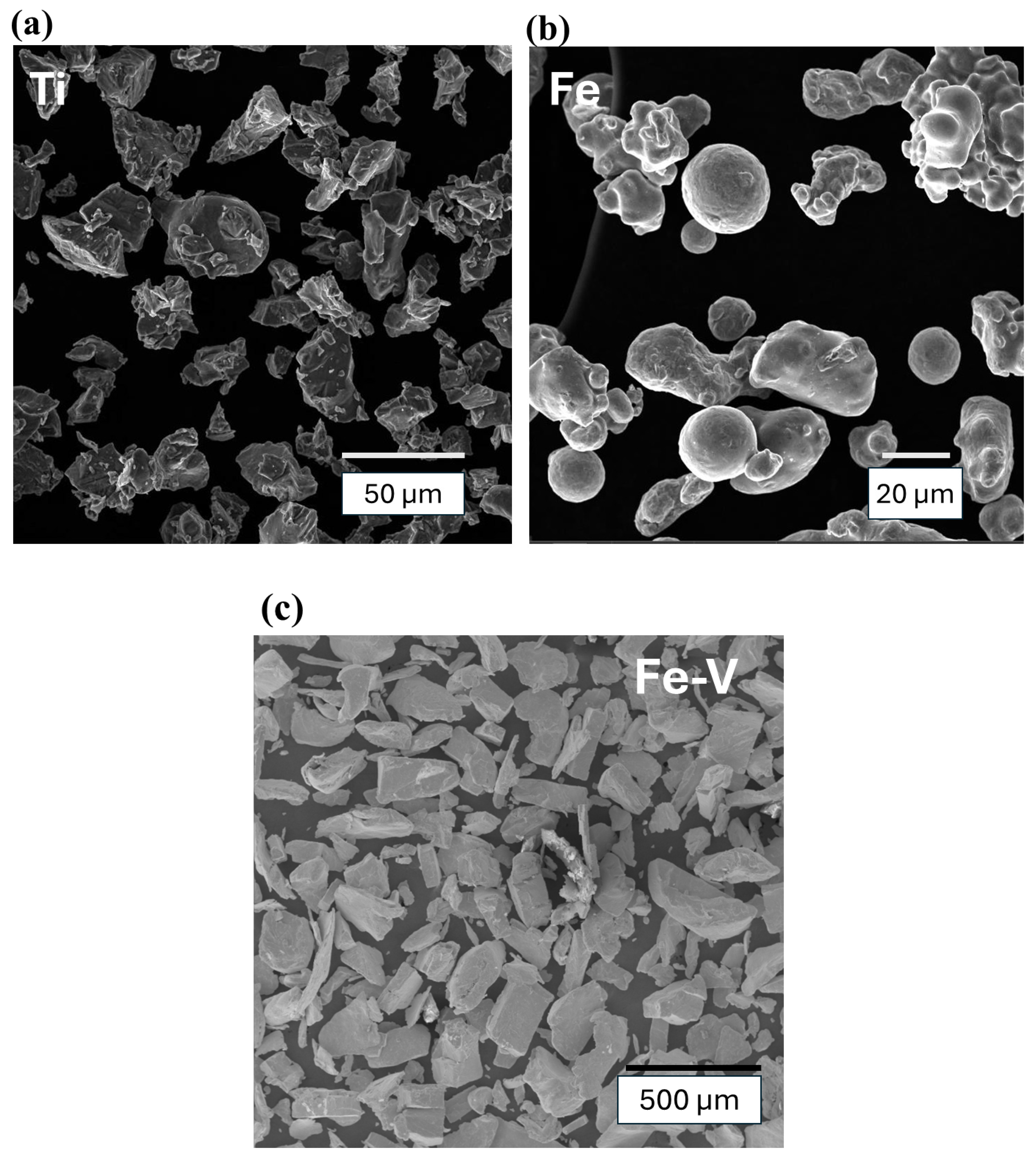
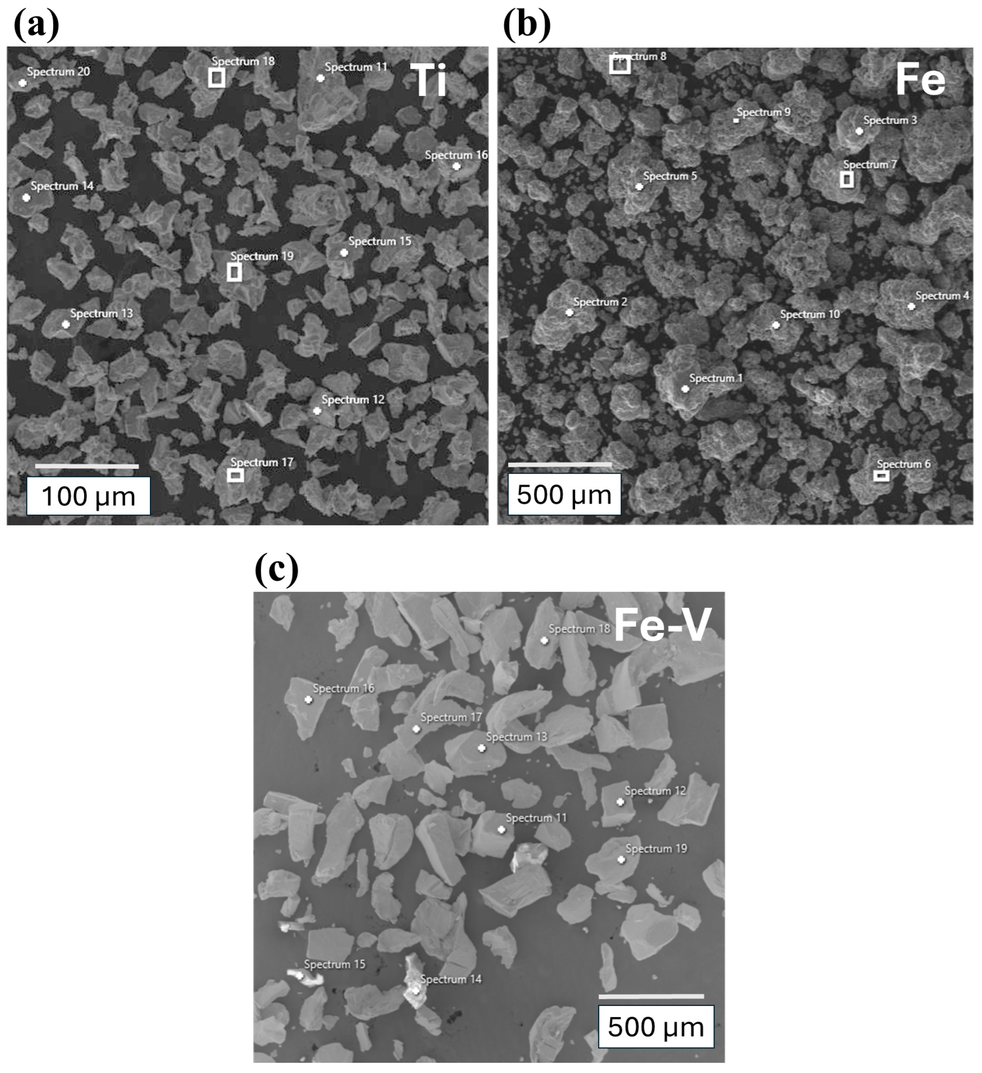
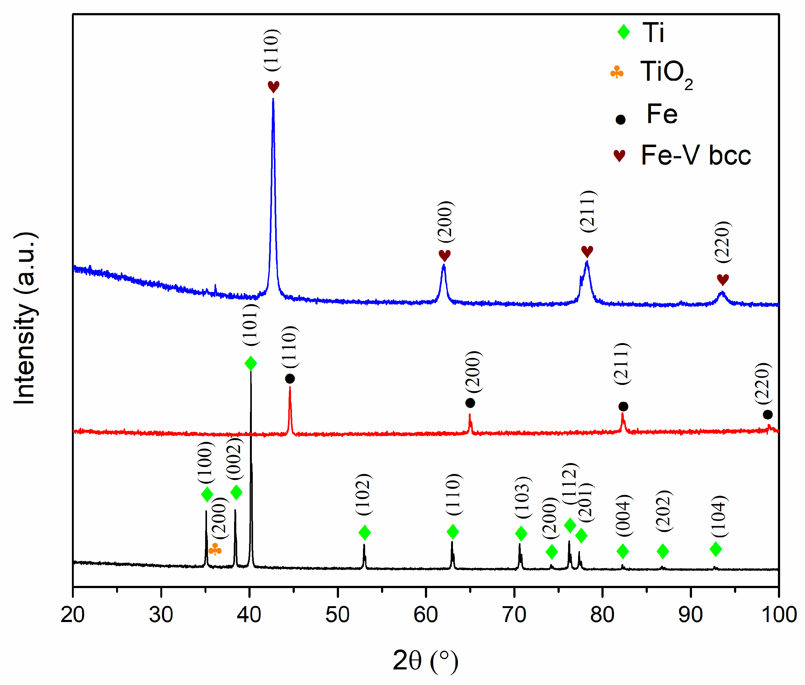
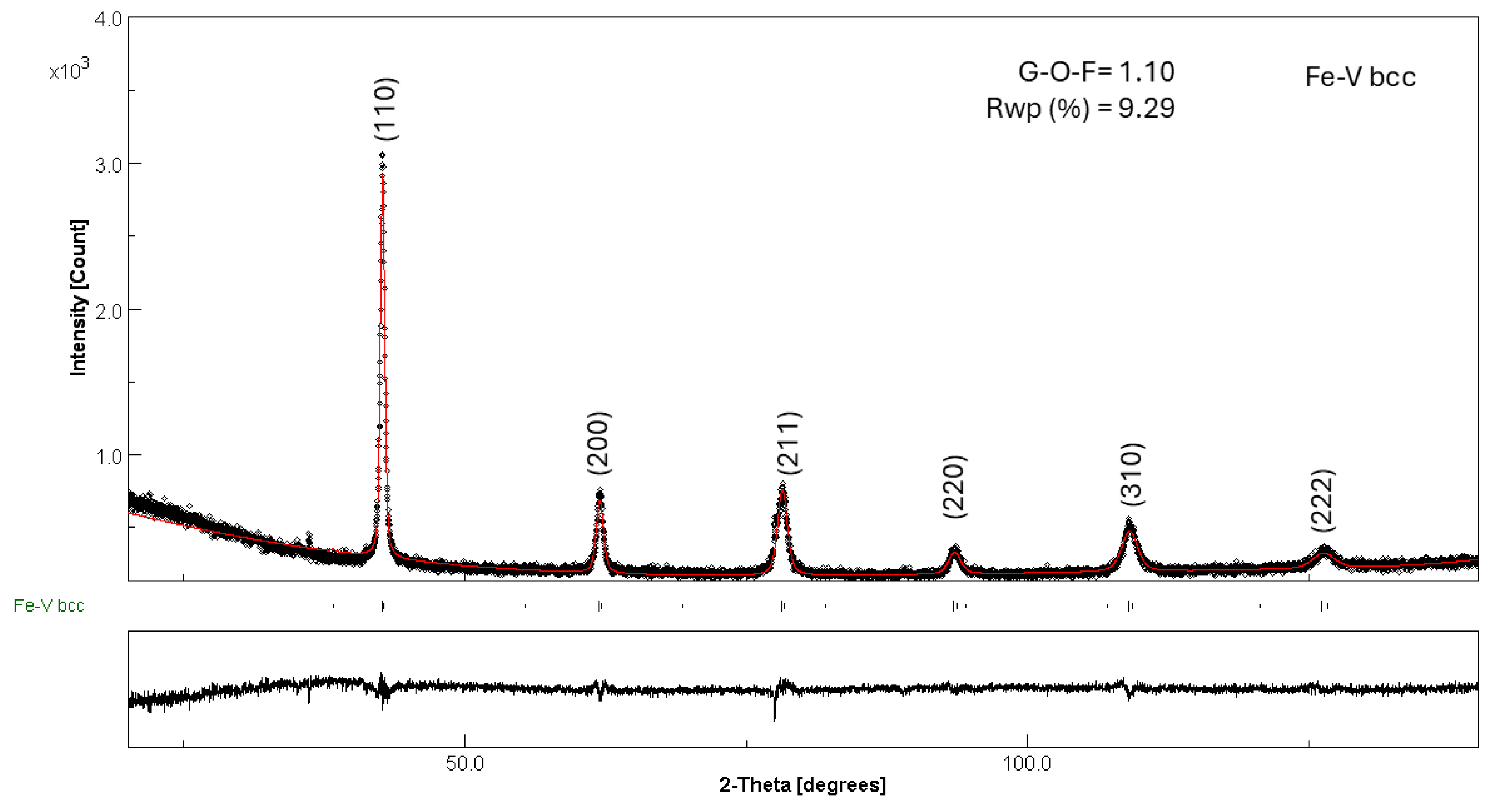
3.1. Starting Materials
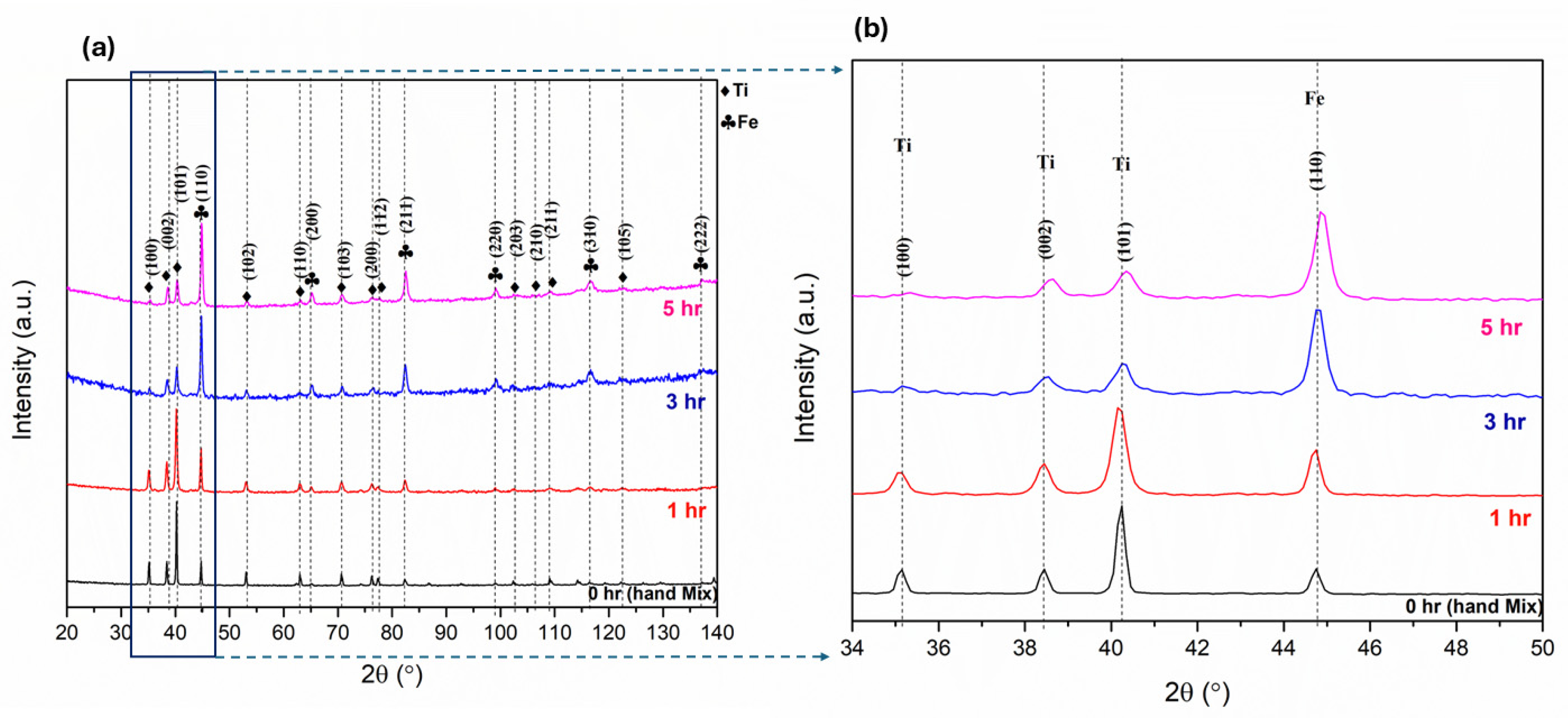
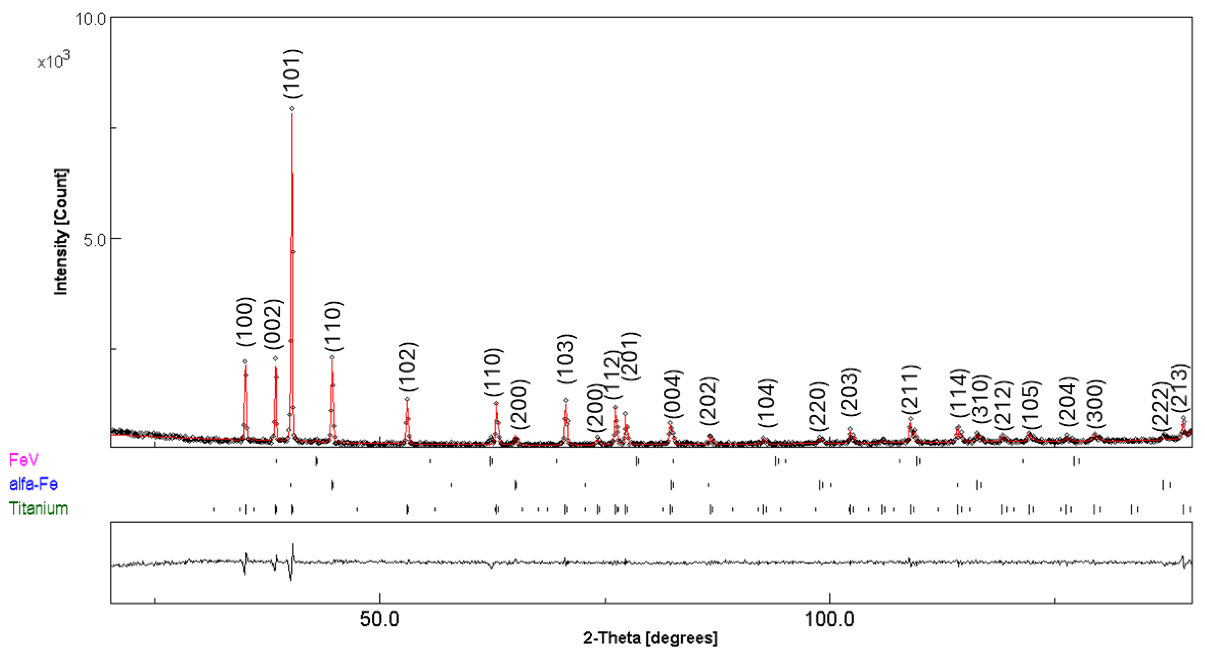
3.2. Mechanical Alloying
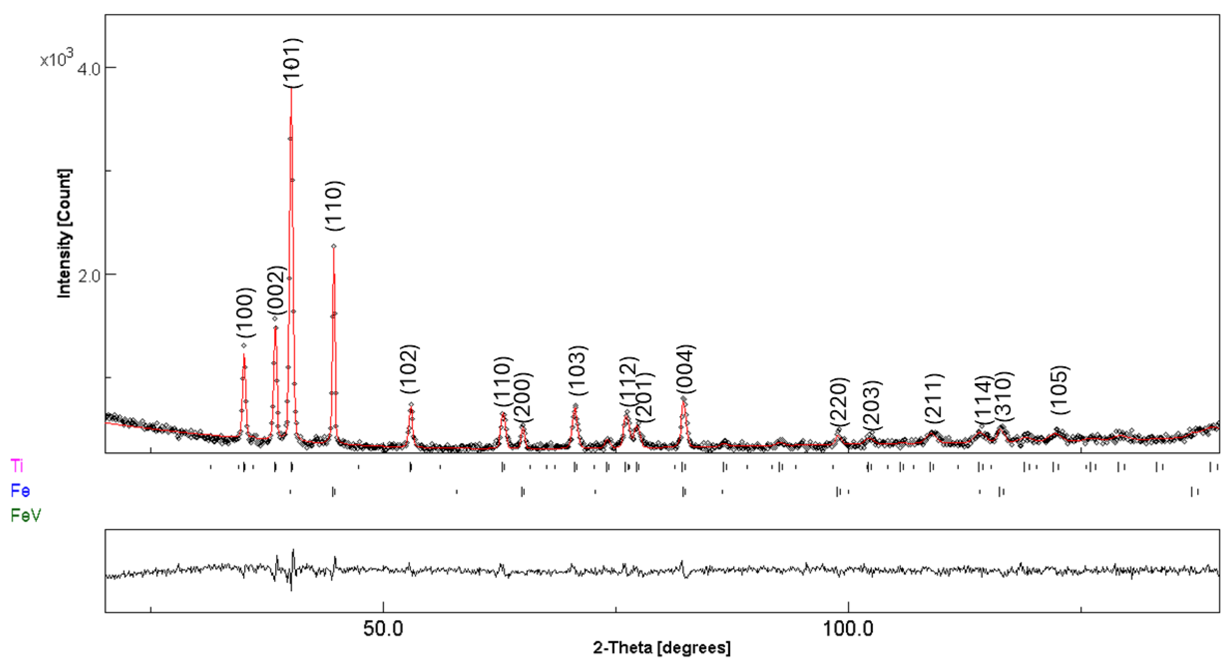
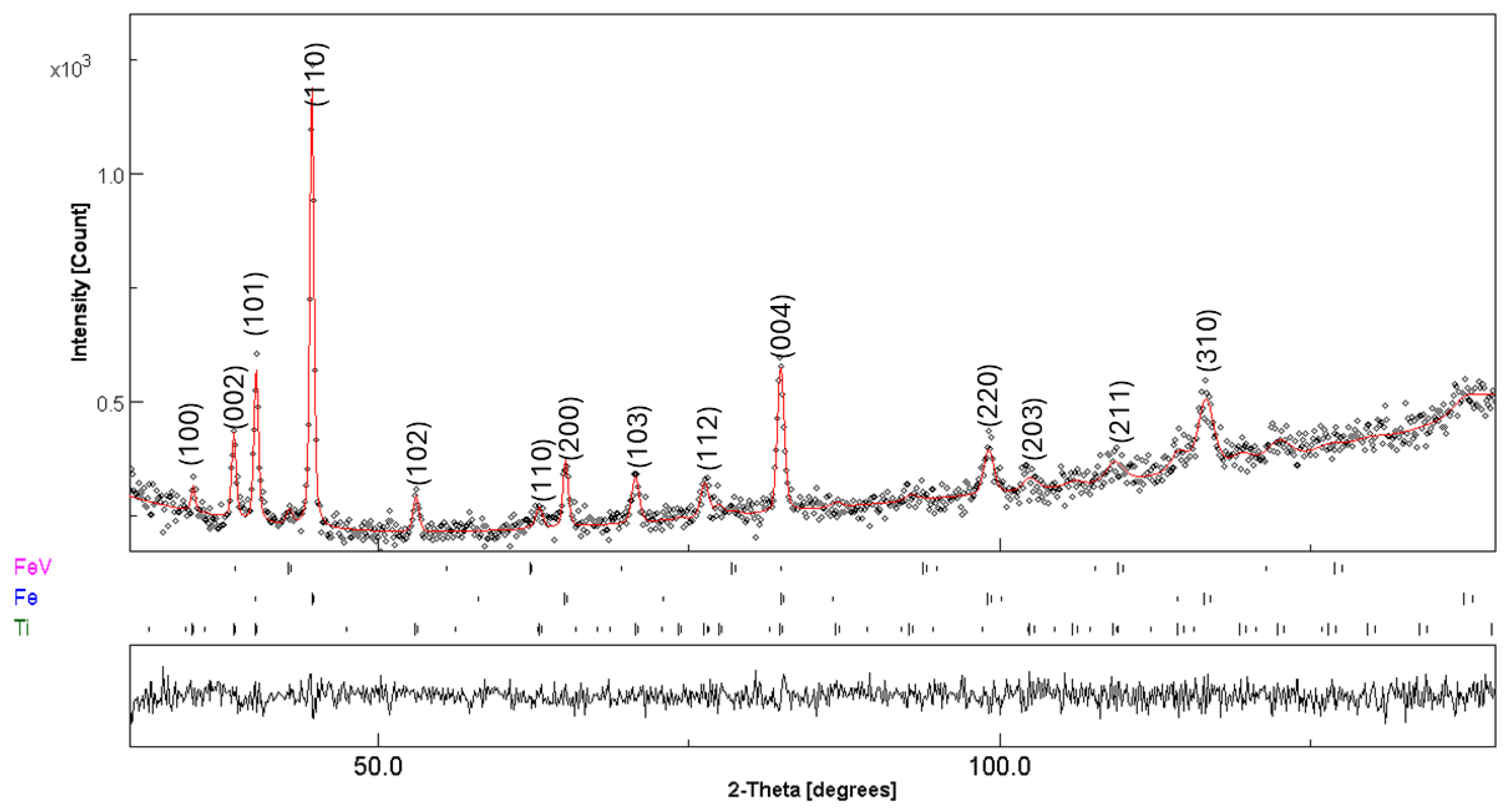
3.3. Post-Compacting and Annealing Treatment
4. Conclusions
Author Contributions
Funding
Data Availability Statement
Acknowledgments
Conflicts of Interest
References
- Nivedhitha, K.S.; Beena, T.; Banapurmath, N.R.; Umarfarooq, M.A.; Ramasamy, V.; Soudagar, M.E.M.; Ağbulut, Ü. Advances in Hydrogen Storage with Metal Hydrides: Mechanisms, Materials, and Challenges. Int. J. Hydrogen Energy 2024, 61, 1259–1273. [Google Scholar] [CrossRef]
- Lototskyy, M.V.; Yartys, V.A.; Pollet, B.G.; Bowman, R.C. Metal Hydride Hydrogen Compressors: A Review. Int. J. Hydrogen Energy 2014, 39, 5818–5851. [Google Scholar] [CrossRef]
- Drawer, C.; Lange, J.; Kaltschmitt, M. Metal Hydrides for Hydrogen Storage—Identification and Evaluation of Stationary and Transportation Applications. J. Energy Storage 2024, 77, 109988. [Google Scholar] [CrossRef]
- Rusman, N.A.A.; Dahari, M. A Review on the Current Progress of Metal Hydrides Material for Solid-State Hydrogen Storage Applications. Int. J. Hydrogen Energy 2016, 41, 12108–12126. [Google Scholar] [CrossRef]
- Bedrunka, M.; Bornemann, N.; Steinebach, G.; Reith, D. A Metal Hydride System for a Forklift: Feasibility Study on on-Board Chemical Storage of Hydrogen Using Numerical Simulation. Int. J. Hydrogen Energy 2022, 47, 12240–12250. [Google Scholar] [CrossRef]
- Yartys, V.A.; Lototskyy, M.V.; Tolj, I.; von Colbe, J.B.; Denys, R.V.; Davids, M.W.; Nyamsi, S.N.; Swanepoel, D.; Berezovets, V.V.; Zavaliy, I.Y.; et al. HYDRIDE4MOBILITY: An EU Project on Hydrogen Powered Forklift Using Metal Hydrides for Hydrogen Storage and H2 Compression. J. Energy Storage 2025, 109, 115192. [Google Scholar] [CrossRef]
- Fiori, C.; Dell’Era, A.; Zuccari, F.; Santiangeli, A.; D’Orazio, A.; Orecchini, F. Hydrides for Submarine Applications: Overview and Identification of Optimal Alloys for Air Independent Propulsion Maximization. Int. J. Hydrogen Energy 2015, 40, 11879–11889. [Google Scholar] [CrossRef]
- Kulshreshtha, S.K.; Sasikala, R.; Pushpa, K.K.; Rao, K.A.; Iyer, R.M. On Activation of FeTi: Surface Effects. Mater. Res. Bull. 1989, 24, 545–550. [Google Scholar] [CrossRef]
- Schober, T. On the Activation of FeTi for Hydrogen Storage. J. Less Common. Met. 1983, 89, 63–70. [Google Scholar] [CrossRef]
- Reilly, J.J.; Wiswall, R.H. Formation and Properties of Iron Titanium Hydride. Inorg. Chem. 1974, 13, 218–222. [Google Scholar] [CrossRef]
- Jung, J.Y.; Lee, Y.S.; Suh, J.Y.; Huh, J.Y.; Cho, Y.W. Tailoring the Equilibrium Hydrogen Pressure of TiFe via Vanadium Substitution. J. Alloys Compd. 2021, 854, 157263. [Google Scholar] [CrossRef]
- Guéguen, A.; Latroche, M. Influence of the Addition of Vanadium on the Hydrogenation Properties of the Compounds TiFe0.9Vx and TiFe0.8Mn0.1Vx (X=0, 0.05 and 0.1). J. Alloys Compd. 2011, 509, 5562–5566. [Google Scholar] [CrossRef]
- Modi, P.; Aguey-Zinsou, K.-F. Titanium-Iron-Manganese (TiFe0.85Mn0.15) Alloy for Hydrogen Storage: Reactivation upon Oxidation. Int. J. Hydrogen Energy 2019, 44, 16757–16764. [Google Scholar] [CrossRef]
- Padhee, S.P.; Roy, A.; Pati, S. Role of Mn-Substitution towards the Enhanced Hydrogen Storage Performance in FeTi. Int. J. Hydrogen Energy 2022, 47, 9357–9371. [Google Scholar] [CrossRef]
- Patel, A.K.; Duguay, A.; Tougas, B.; Schade, C.; Sharma, P.; Huot, J. Microstructure and First Hydrogenation Properties of TiFe Alloy with Zr and Mn as Additives. Int. J. Hydrogen Energy 2020, 45. [Google Scholar] [CrossRef]
- Edalati, K.; Matsuda, J.; Iwaoka, H.; Toh, S.; Akiba, E.; Horita, Z. High-Pressure Torsion of TiFe Intermetallics for Activation of Hydrogen Storage at Room Temperature with Heterogeneous Nanostructure. Int. J. Hydrogen Energy 2013, 38, 4622–4627. [Google Scholar] [CrossRef]
- Chiang, C.-H.; Chin, Z.-H.; Perng, T.-P. Hydrogenation of TiFe by High-Energy Ball Milling. J. Alloys Compd. 2000, 307, 259–265. [Google Scholar] [CrossRef]
- Emami, H.; Edalati, K.; Matsuda, J.; Akiba, E.; Horita, Z. Hydrogen Storage Performance of TiFe after Processing by Ball Milling. Acta Mater. 2015, 88, 190–195. [Google Scholar] [CrossRef]
- Manna, J.; Tougas, B.; Huot, J. Mechanical Activation of Air Exposed TiFe + 4 Wt% Zr Alloy for Hydrogenation by Cold Rolling and Ball Milling. Int. J. Hydrogen Energy 2018, 43, 20795–20800. [Google Scholar] [CrossRef]
- Barale, J.; Dematteis, E.M.; Capurso, G.; Neuman, B.; Deledda, S.; Rizzi, P.; Cuevas, F.; Baricco, M. TiFe0.85Mn0.05 Alloy Produced at Industrial Level for a Hydrogen Storage Plant. Int. J. Hydrogen Energy 2022, 47, 29866–29880. [Google Scholar] [CrossRef]
- Bellosta von Colbe, J.M.; Puszkiel, J.; Capurso, G.; Franz, A.; Benz, H.U.; Zoz, H.; Klassen, T.; Dornheim, M. Scale-up of Milling in a 100 L Device for Processing of TiFeMn Alloy for Hydrogen Storage Applications: Procedure and Characterization. Int. J. Hydrogen Energy 2019, 44, 29282–29290. [Google Scholar] [CrossRef]
- Hotta, H.; Abe, M.; Kuji, T.; Uchida, H. Synthesis of Ti-Fe Alloys by Mechanical Alloying. J. Alloys Compd. 2007, 439, 221–226. [Google Scholar] [CrossRef]
- Eckert, J.; Schultz, L.; Urban, K. Synthesis of Ni-Ti and Fe-Ti Alloys by Mechanical Alloying: Formation of Amorphous Phases and Extended Solid Solutions. J. Non-Cryst. Solids 1991, 127, 90–96. [Google Scholar] [CrossRef]
- Jurczyk, M.; Jankowska, E.; Nowak, M.; Jakubowicz, J. Nanocrystalline Titanium-Type Metal Hydride Electrodes Prepared by Mechanical Alloying. J. Alloys Compd. 2002, 336, 265–269. [Google Scholar] [CrossRef]
- Zadorozhnyi, M.Y.; Kaloshkin, S.D.; Klyamkin, S.N.; Bermesheva, O.V.; Zadorozhnyi, V.Y. Mechanochemical Synthesis of a TiFe Nanocrystalline Intermetallic Compound and Its Mechanical Alloying with Third Component. Metal. Sci. Heat. Treat. 2013, 54, 461–465. [Google Scholar] [CrossRef]
- Chu, B.-L.; Lee, S.-M.; Perng, T.-P. Preparation and Hydrogen Absorption Property of Amorphous Ti50Fe50. Int. J. Hydrogen Energy 1991, 16, 413–416. [Google Scholar] [CrossRef]
- Jung, C.B.; Kim, J.H.; Lee, K.S. Electrode Characteristics of Nanostructured TiFe and ZrCr2 Type Metal Hydride Prepared by Mechanical Alloying. Nanostruct. Mater. 1997, 8, 1093–1104. [Google Scholar] [CrossRef]
- Abe, M.; Kuji, T. Hydrogen Absorption of TiFe Alloy Synthesized by Ball Milling and Post-Annealing. J. Alloys Compd. 2007, 446–447, 200–203. [Google Scholar] [CrossRef]
- Zadorozhnyy, V.; Klyamkin, S.; Zadorozhnyy, M.; Bermesheva, O.; Kaloshkin, S. Hydrogen Storage Nanocrystalline TiFe Intermetallic Compound: Synthesis by Mechanical Alloying and Compacting. Int. J. Hydrogen Energy 2012, 37, 17131–17136. [Google Scholar] [CrossRef]
- Shang, Y.; Liu, S.; Liang, Z.; Pyczak, F.; Lei, Z.; Heidenreich, T.; Schökel, A.; Kai, J.; Gizer, G.; Dornheim, M.; et al. Developing Sustainable FeTi Alloys for Hydrogen Storage by Recycling. Commun. Mater. 2022, 3, 101. [Google Scholar] [CrossRef]
- Rasheed, M.Z.; Haack, A.; Bumby, C.W.; Dahm, K.; Ramond, M.; Cao, P.; Pistidda, C. Production of TiFe Hydrogen-Storage Material by Direct Reduction of Ilmenite Mineral Sand. ACS Appl. Energy Mater. 2025, 8, 1580–1588. [Google Scholar] [CrossRef]
- Dematteis, E.M.; Berti, N.; Cuevas, F.; Latroche, M.; Baricco, M. Substitutional Effects in TiFe for Hydrogen Storage: A Comprehensive Review. Mater. Adv. 2021, 2, 2524–2560. [Google Scholar] [CrossRef]
- Cacciamani, G.; De Keyzer, J.; Ferro, R.; Klotz, U.E.; Lacaze, J.; Wollants, P. Critical Evaluation of the Fe–Ni, Fe–Ti and Fe–Ni–Ti Alloy Systems. Intermet. 2006, 14, 1312–1325. [Google Scholar] [CrossRef]
- Padhee, S.P.; Sakaki, K.; Shukla, V.; Hwang, K.; Cho, Y.W.; Lee, Y.-S. Optimizing Hydrogen Storage in TiFe–V Alloys: Influence of Sample Purity and Heat Treatment. Int. J. Hydrogen Energy 2025, 138, 874–883. [Google Scholar] [CrossRef]
- Lutterotti, L.; Matthies, S.; Wenk, H.-R.; Schultz, A.S.; Richardson, J.W., Jr. Combined Texture and Structure Analysis of Deformed Limestone from Time-of-Flight Neutron Diffraction Spectra. J. Appl. Phys. 1997, 81, 594–600. [Google Scholar] [CrossRef]
- Diaz-Caraveo, C.; Bimal, K.C.; San Martín, J.A.M. Lattice Dynamics and Free Energies of Fe-V Alloys with Thermal and Chemical Disorder. J. Phys. Condens. Matter 2024, 36, 44. [Google Scholar] [CrossRef]
- Sakher, E.; Loudjani, N.; Benchiheub, M.; Bououdina, M. Influence of Milling Time on Structural and Microstructural Parameters of Ni50Ti50 Prepared by Mechanical Alloying Using Rietveld Analysis. J. Nanomater. 2018, 2018, 1–11. [Google Scholar] [CrossRef]
- Fouzia, H.; Mamoun, F.; Naouel, H.; Linda, A.; Goussem, M.; Said, M.; Mohammed, A.S.; Alex, M.; Iost, A.; Weiß, S.; et al. The Effect of Milling Time on the Microstructure and Mechanical Properties of Ti-6Al-4Fe Alloys. Mater. Today Commun. 2021, 27, 102428. [Google Scholar] [CrossRef]
- Murty, B.S.; Rao, M.M.; Ranganathan, S. Nanocrystalline Phase Formation and Extension of Solid Solubility by Mechanical Alloying in Ti-Based Systems. Nanostruct. Mater. 1993, 3, 459–467. [Google Scholar] [CrossRef]
- Suryanarayana, C. Mechanical Alloying and Milling. Prog. Mater. Sci. 2001, 46, 1–184. [Google Scholar] [CrossRef]
- Jing, Z.; Cao, Q.Z.; Huang, G.H.; Huang, J.L. Effect of Ni Addition on Formation of Nanocrystalline Phase during Mechanical Alloying of (Fe Al)-40(60) at.% Ni and (Fe Al3)-10(30) at.% Ni Powders. Appl. Mech. Mater. 2013, 275–277, 1814–1817. [Google Scholar] [CrossRef]
- Benjamin, J.S. Dispersion Strengthened Superalloys by Mechanical Alloying. Metall. Trans. 1970, 1, 2943–2951. [Google Scholar] [CrossRef]
- El-Eskandarany, M.S. Mechanical Alloying: For Fabrication of Advanced Engineering Materials; El-Eskandarany, M.S., Ed.; William Andrew Publishing: Norwich, NY, USA, 2001; ISBN 978-0-8155-1462-6. [Google Scholar]
- Nayebossadri, S.; Greenwood, C.J.; Book, D. Evaluating Some Design Criteria for TiFe-Based Ternary Hydrogen Storage Alloys. J. Alloys Compd. 2023, 947, 169456. [Google Scholar] [CrossRef]
- Liu, H.; Zhang, J.; Sun, P.; Zhou, C.; Liu, Y.; Fang, Z.Z. The Mechanistic Role of Ti4Fe2O1-x Phases in the Activation of TiFe Alloys for Hydrogen Storage. Int. J. Hydrogen Energy 2023, 48, 32011–32024. [Google Scholar] [CrossRef]
- Williams, M.; Lototsky, M.V.; Davids, M.W.; Linkov, V.; Yartys, V.A.; Solberg, J.K. Chemical Surface Modification for the Improvement of the Hydrogenation Kinetics and Poisoning Resistance of TiFe. J. Alloys Compd. 2011, 509, S770–S774. [Google Scholar] [CrossRef]
- Davids, M.W.; Lototskyy, M. Influence of Oxygen Introduced in TiFe-Based Hydride Forming Alloy on Its Morphology, Structural and Hydrogen Sorption Properties. Int. J. Hydrogen Energy 2012, 37, 18155–18162. [Google Scholar] [CrossRef]


| Fe | 1 | 2 | 3 | 4 | 5 | 6 | 7 | 8 | 9 | 10 |
|---|---|---|---|---|---|---|---|---|---|---|
| O | 1.8 | - | - | - | - | 2.9 | 2.1 | 1.1 | 1.1 | 1.3 |
| Fe | 98.2 | 100 | 100 | 100 | 100 | 97.1 | 97.9 | 98.9 | 98.9 | 98.7 |
| Ti | 11 | 12 | 13 | 14 | 15 | 16 | 17 | 18 | 19 | 20 |
| O | 14.9 | - | - | - | - | 12.2 | - | - | 12.9 | |
| Ti | 100 | 85.1 | 100 | 100 | 100 | 100 | 87.8 | 100 | 100 | 87.1 |
| Fe–V | 11 | 12 | 13 | 14 | 15 | 16 | 17 | 18 | 19 | - |
| O | - | - | - | - | 43.23 | - | - | - | - | - |
| Al | - | - | - | - | 56.77 | - | - | - | - | - |
| Fe | 9.8 | 17.8 | 16.7 | 15.7 | - | 17.2 | 16.3 | 13.9 | 23.5 | - |
| V | 90.2 | 82.2 | 83.3 | 84.3 | - | 82.8 | 83.7 | 86.1 | 76.5 | - |
| Hand-Mixed (No Milling) | ||||
|---|---|---|---|---|
| Phase | Phase Fractions (wt%) | Lattice Parameter (Å) | Crystallite Size (nm) | Microstrain × 10−3 (%) |
| Fe | 24(1) | a = 2.8672(4) | 110(1) | 0.2(1) |
| Ti | 74(1) | a = 2.9517(2) c = 4.6871(1) | 263(1) | 0.3(1) |
| Fe–V | 2(1) | a = 2.9834(4) | 156(2) | 0.2(1) |
| 1 h MA | ||||
| Fe | 22(1) | a = 2.8695(2) | 118(1) | 2.0(1) |
| Ti | 76(1) | a = 2.9562(3) c = 4.6908(1) | 110(2) | 3.0(1) |
| Fe–V | 2(1) | a = 2.9835(4) | 154(1) | 0.2(1) |
| 3 h MA | ||||
| Fe | 67(1) | a = 2.8649(2) | 60(1) | 1(1) |
| Ti | 30(1) | a = 2.9491(3) c = 4.6825(1) | 85(1) | 3(1) |
| Fe–V | 3(1) | a = 2.9861(2) | 100 (2) | 4(1) |
| 5 h MA | ||||
| Fe | 60(1) | a = 2.8613(2) | 56(1) | 2(1) |
| Ti | 38(1) | a = 2.9456(3) c = 4.6737(1) | 86(1) | 4(1) |
| Fe–V | 2(1) | a = 2.9737(2) | 99 (2) | 5(2) |
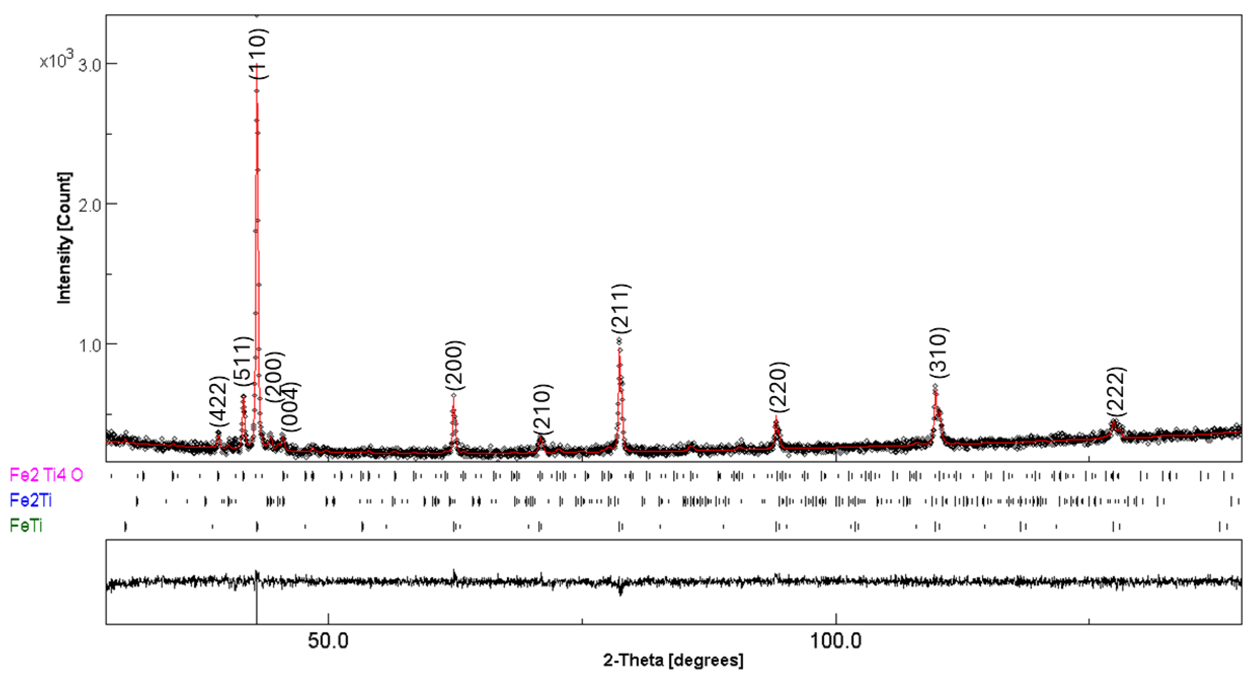
| Phase | Fraction (wt%) | Lattice Parameter (Å) | Crystallite Size (nm) | Microstrain × 10−3 (%) |
|---|---|---|---|---|
| FeTi | 90(1) | a = 2.9767(2) | 118(1) | 1(1) |
| Fe2Ti | 4(1) | a = 4.7478(2) c = 8.0430(1) | 99(1) | 3(4) |
| Fe2Ti4O | 6(1) | a = 11.2725(1) | 123(1) | 1(1) |
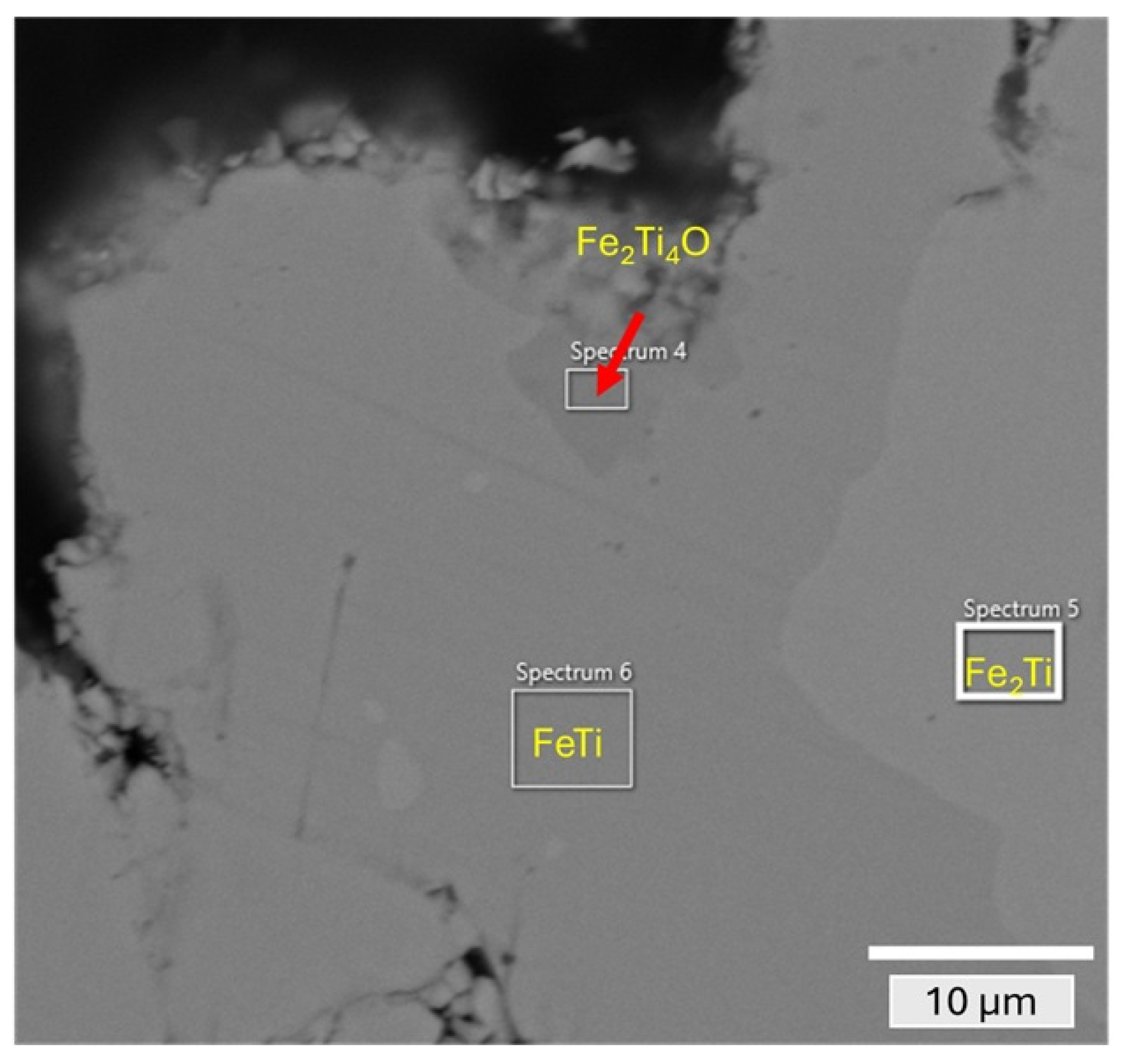
| Phase | Ti (at%) | Fe (at%) | V (at%) | O (at%) |
|---|---|---|---|---|
| FeTi (spectrum 6) | 50.7 | 49.3 | - | - |
| Fe2Ti (spectrum 5) | 35.3 | 64.7 | - | - |
| Fe2Ti4O (spectrum 4) | 57.3 | 32.3 | 1.2 | 9.2 |
Disclaimer/Publisher’s Note: The statements, opinions and data contained in all publications are solely those of the individual author(s) and contributor(s) and not of MDPI and/or the editor(s). MDPI and/or the editor(s) disclaim responsibility for any injury to people or property resulting from any ideas, methods, instructions or products referred to in the content. |
© 2025 by the authors. Licensee MDPI, Basel, Switzerland. This article is an open access article distributed under the terms and conditions of the Creative Commons Attribution (CC BY) license (https://creativecommons.org/licenses/by/4.0/).
Share and Cite
Patel, A.K.; Violi, D.; Lorenzon, I.; Luetto, C.; Rizzi, P.; Baricco, M. Synthesis of a Vanadium-Substituted Fe–Ti-Based Ternary Alloy via Mechanical Alloying, Compacting, and Post-Annealing. Metals 2025, 15, 723. https://doi.org/10.3390/met15070723
Patel AK, Violi D, Lorenzon I, Luetto C, Rizzi P, Baricco M. Synthesis of a Vanadium-Substituted Fe–Ti-Based Ternary Alloy via Mechanical Alloying, Compacting, and Post-Annealing. Metals. 2025; 15(7):723. https://doi.org/10.3390/met15070723
Chicago/Turabian StylePatel, Abhishek Kumar, Davide Violi, Ivan Lorenzon, Carlo Luetto, Paola Rizzi, and Marcello Baricco. 2025. "Synthesis of a Vanadium-Substituted Fe–Ti-Based Ternary Alloy via Mechanical Alloying, Compacting, and Post-Annealing" Metals 15, no. 7: 723. https://doi.org/10.3390/met15070723
APA StylePatel, A. K., Violi, D., Lorenzon, I., Luetto, C., Rizzi, P., & Baricco, M. (2025). Synthesis of a Vanadium-Substituted Fe–Ti-Based Ternary Alloy via Mechanical Alloying, Compacting, and Post-Annealing. Metals, 15(7), 723. https://doi.org/10.3390/met15070723