Article

Influence of Friction-Stir-Processing Parameters on the Microstructure and Local Mechanical Properties of an Aluminium-6% Magnesium-H18 Alloy

1
Department of Mechanical Engineering, École de Technologie Supérieure, 1100 rue Notre-Dame Ouest, Montréal, QC H3C1K3, Canada
2
Department of Mathematics and Industrial Engineering, Polytechnic of Montreal, 2500 Chemin de Polytechnique, Montréal, QC H3T0A3, Canada
*
Author to whom correspondence should be addressed.
Metals 2025, 15(7), 709; https://doi.org/10.3390/met15070709
Submission received: 19 May 2025 / Revised: 18 June 2025 / Accepted: 22 June 2025 / Published: 26 June 2025

Abstract

One major challenge of friction stir processing (FSP) is its sensitivity to parameters like advancing and rotational speeds. This study examined the effect of tool travel speed on the microstructural evolution and mechanical properties of a new-generation Al-6Mg alloy. Optical and electron microscopy, EBSD, and shear-punch testing (SPT) were used. Two travel speeds, 50 and 120 mm/min, revealed significant differences in microstructure and properties at ambient temperature. EBSD provided misorientation maps and boundary fraction data. Microstructure analysis showed continuous dynamic recrystallization in the nugget zone, with finer grains observed at the higher speed. Microhardness was greater on both sides at 120 mm/min. The TMAZ showed elongated grains at 120 mm/min, while recrystallized grains were more prominent at 50 mm/min. In the HAZ, partial recrystallization occurred at 120 mm/min, whereas extensive recrystallization was observed at 50 mm/min. The SPT results indicated variations in stiffness between advancing and retreating sides, especially 2 mm from the nugget center. At 10 and 20 mm from the center, higher stiffness and strength were recorded at 120 mm/min. This study established correlations between joint stiffness, grain misorientation, and travel speed.

1. Introduction

Friction stir processing (FSP) is a technique derived from friction stir welding (FSW), and its effect on properties such as ductility, strength, resistance to wear, creep, and fatigue has been investigated by many researchers [1,2,3]. A significant increase in the ductility of AA7072-T6 and AA5083-O aluminum alloys has been detected after FSP treatment was conducted at a deeper depth, while a limited increase has been observed when the FSP is conducted superficially [1]. The hardness, intergranular corrosion resistance, and wear resistance of FSPed aluminium alloy AA5083 specimens simultaneously increases due to the observed grain refinement, dispersion, and partial dissolution of the secondary phase [2]. A significant increase in the microhardness, tensile, and creep strength has been observed in FSPed AZ91 magnesium alloy plates at room temperature. FSP is conducted by plunging a rotating tool with a specific geometry into the metallic raw material, which then travels over the surface at a desired travel speed. During FSP, localized heating and intense plastic deformation are produced at the surface and in the subsurface regions. This thermo-mechanical process results in significant grain refinement and eliminates defects, such as porosities. The principal variables of the process are tool geometry, rotational speed, travel speed, tilt angle, downward axial force, and the number of travel cycles. Each of them influences, to a certain degree, the level of frictional heat generated at the tool–material interface and has a determining impact on the quality of the FSPed part. Among the above variables, tool travel speed has been identified as the parameter with the most pronounced influence on joint quality [3,4]. Moreover, it is also the process parameter that can be accurately controlled and monitored.
The benefits of FSP in improving the mechanical properties of the weld zone and the TMAZ have been investigated in different alloys, including aluminium alloys [5,6,7,8], magnesium alloys [9,10,11], copper alloys [12,13], titanium alloys [14,15,16,17], and nickel-based alloys [18]. Patel et al. [19] reviewed the benefits of FSP, particularly its impact on grain refinement in different alloys such as aluminum alloys, including steels, Al-base, Mg-base, and Cu-base alloys. However, no data has been published on the recently developed high-magnesium containing aluminum alloys. It is also worth mentioning that while FSP brings modifications to the surface and a small subsurface area, little data is available on the correlation between the local texture and the local mechanical properties of the FSP-affected zones. To this end, shear-punch testing (SPT) is considered a good candidate for evaluating local mechanical properties, and it has been successfully applied to evaluate the local mechanical properties of friction stir-welded joints. Specifically, Guduru et al. [20] used SPT to study the evolution of the mechanical properties for different materials by using a 1% offset criterion in conjunction with normalized shear-punch curves. They developed an SPT master curve that is independent of the thickness of the sample for large intervals of thickness for the materials they tested in their study. In another study, Fall et al. [21] used SPT to evaluate the local mechanical properties of an FSWed Ti alloy. They found that the heat-affected zone (HAZ) closest to the base material had the lowest mechanical properties of the joint. Electron backscatter diffraction (EBSD) has been extensively used as an efficient and effective characterization method to determine the impact of thermo-mechanical processes on the evolution of the microstructure. Several studies were conducted on aluminum alloys of the 6xxx and 7xxx series [22,23,24], and correlations were established between the evolution of the microstructure and the FSW parameters. Monajati et al. [25] used a combination of EBSD and in situ SEM nano-indentation to study the influence of FSW parameters on grain size evolution in the banded zones of an aluminum alloy FSW joint and correlated it with the local mechanical properties using SPT.
In the present work, plates of cold-worked aluminium-6% magnesium alloys were friction stir processed at different travel speeds. The evolution in grain size, as well as the local and global mechanical properties, was determined. The results obtained were then correlated with grain misorientation maps obtained from the EBSD investigation. The microstructural and mechanical results were then correlated and related to the tool travel speed.

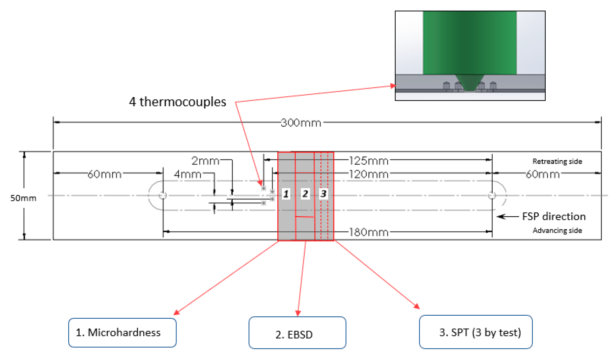
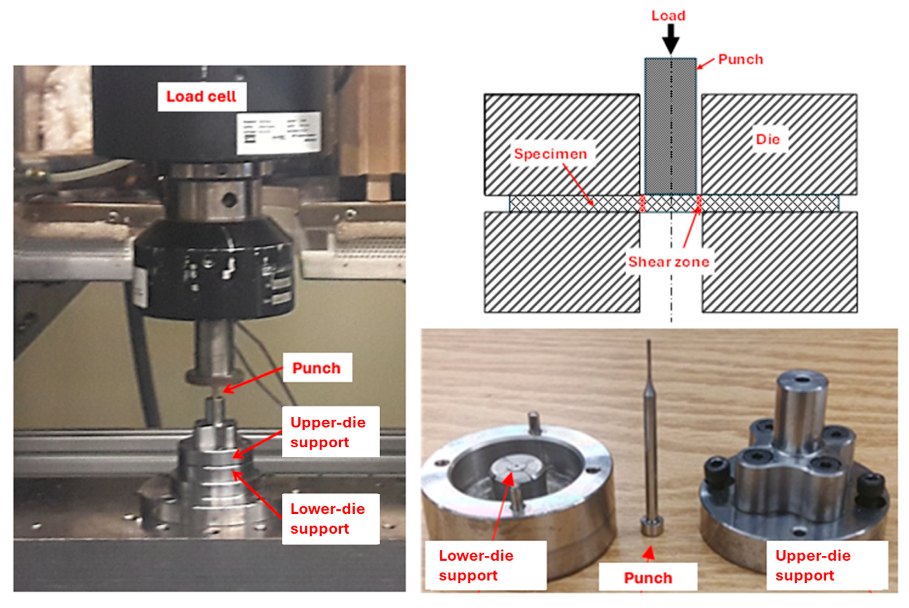
2. Materials and Methods

Aluminium-6% magnesium-H18 (cold-worked) alloy rolled plates with dimensions of 300 × 50 × 3 mm3 were used. The chemical composition of the alloy was determined using the SPECTROMAXx spark spectrometer (Kleve, Germany), and the average of five sparks is presented in Table 1. Tensile tests were also conducted in accordance with ASTM E8/E8M-6a [26] to evaluate the tensile mechanical properties of the base metal. The results presented in Table 2 are the average of three tests, and the error represents the standard deviation of these three tests. A series of FSP runs was conducted using a Bridgeport interact-400 milling machine (Sanford, FL, USA), with the tool perpendicular to the rolling direction at a constant tool rotational speed of 800 rpm. Two travel speeds of the work plate crosshead were used, 50 mm/min and 120 mm/min. A Tungsten carbide tool with a shoulder diameter of 16 mm, a concentric pin (truncated cone) with a height of 2.8 mm, and a base and tip diameter of 5 and 1.77 mm, respectively, was employed. Four K-type thermocouples in contact with the plate were used to accurately measure the temperature evolution during FSP. These were installed beneath the plate at 2 mm and 4 mm from the joint centerline, on both the advancing side (AS) and the retreating side (RS), at a depth of 1.5 mm. Three locations (refer to Figure 1) were identified to conduct (1) a Vickers microhardness test using an automatic Clemex CMT machine (Longueuil, QC, Canada) under a load of 50 g and 10 s of dwell time, (2) microstructure investigations using a Hitachi SU-8230 Field-Emission Scanning Electron Microscope (FE-SEM, Tokyo, Japan) equipped with a Bruker e-FlashHR EBSD detector (Emeryville, CA, USA), and (3) shear-punch tests (SPT) using an Alliance RF/200 MTS machine (Tokyo, Japan) equipped with a 10 kN load cell. The set-up used for the shear-punch tests is shown in Figure 2.
EBSD samples were prepared according to the standard procedures for specimen preparation. Also, ion milling was conducted by using a Hitachi IM4000Plus device (Schaumburg, IL, USA) just prior to the EBSD acquisition. Three SPT specimens were prepared by cutting a slice (≈1 mm thick) for each testing condition, followed by polishing to approximately 0.65 mm and finally etching by Keller’s reagent to reveal the FSP area. The punches were spaced 2 mm apart and covered the different zones of the FSPed material. Microhardness measurements were conducted across the FSP-treated line for each sample. A total of 48 indentations were made on each zone, three for each sample, to get a reliable 2D representation in each area of the FSP test.

3. Results and Discussion

A thorough examination of the cross-section of the FSPed sheet highlights the presence of three distinct zones in its microstructure: the heat-affected zone (HAZ), adjacent to the base material which is affected by the generated heat due to the stirring action; the thermo-mechanically affected zone (TMAZ), affected by the stirring’s generated heat and partially deformed under the effect of the tool rotation; and the nugget zone, located under the tool shoulder and consisting of an upper nugget zone (UNZ) and a lower nugget zone (LNZ), which underwent the most severe plastic deformation and reached the highest temperatures, leading to significant microstructural changes.

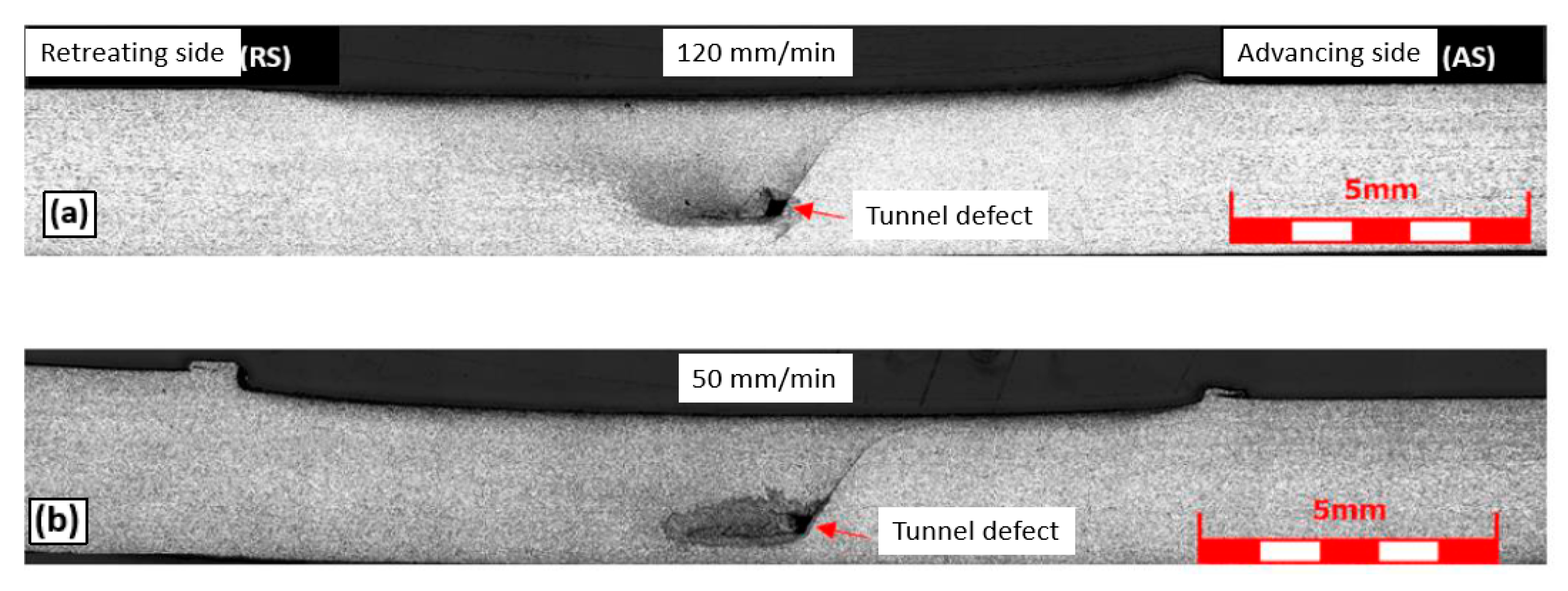
3.1. Macroscopic Examination and Thermal Mapping

Global views of the FSPed regions for both traveling speeds are presented in Figure 3. The top surface of the FSPed regions has an irregular shape, which is more significant for the lower travel speed (Figure 3b). In addition, both FSPed regions show a tunnel defect at the root, towards the advancing side. Similar defects were reported by Nakamura et al. [27] and Fujii et al. [28]. This defect is attributed to the low metal fluidity caused by an insufficient heat input. It could be avoided by optimizing the process parameters. However, the presence of such a defect does not affect the objectives of the present study. Also, their positions do not affect the mechanical tests conducted.

3.2. Microhardness of the Processed Regions

The material response to the change in travel speed in the FSPed regions is shown in Figure 4 and Figure 5. At the travel speed of 50 mm/min, the Vickers microhardness measurements are uniform (≈87–93 HV) up to approximately 10 mm away from the center of the stir zone. Therefore, no significant difference is observed among the nugget zones (the lower and the upper), the TMAZ, and the beginning of the HAZ. From approximately 10 mm, a faint microhardness rising to around 99 HV is observed in the retreating side and around 109 HV in the advancing side of the plate.
At the higher travel speed (120 mm/min), the nugget zones (NZ) exhibit microhardness values slightly higher than those for the 50 mm/min travel speed and are uniform up to approximately 7 mm from the center. Otherwise, the microhardness on both sides (RS and AS) of the FSPed zones rises to significantly higher values than those obtained at a travel speed of 50 mm/min, reaching more than 120 HV on the retreating side and 130 HV on the advancing side.
The observed difference in hardness at different travel speeds can be attributed to the finer grains at 120 mm/min resulting from limited grain growth, as will be discussed in the following sections.
At both travel speeds, the slight difference in microhardness between the RS and the AS can also be explained by the grain size difference, as described in the following section.
Wang et al. [29] and Kalinenko et al. [30] also reported a similar trend in hardness evolution, for a friction stir-welded Al–Li alloy and a high heat-input friction stir-welded 6013 aluminum alloy, respectively.

3.3. Microstructural Characteristics

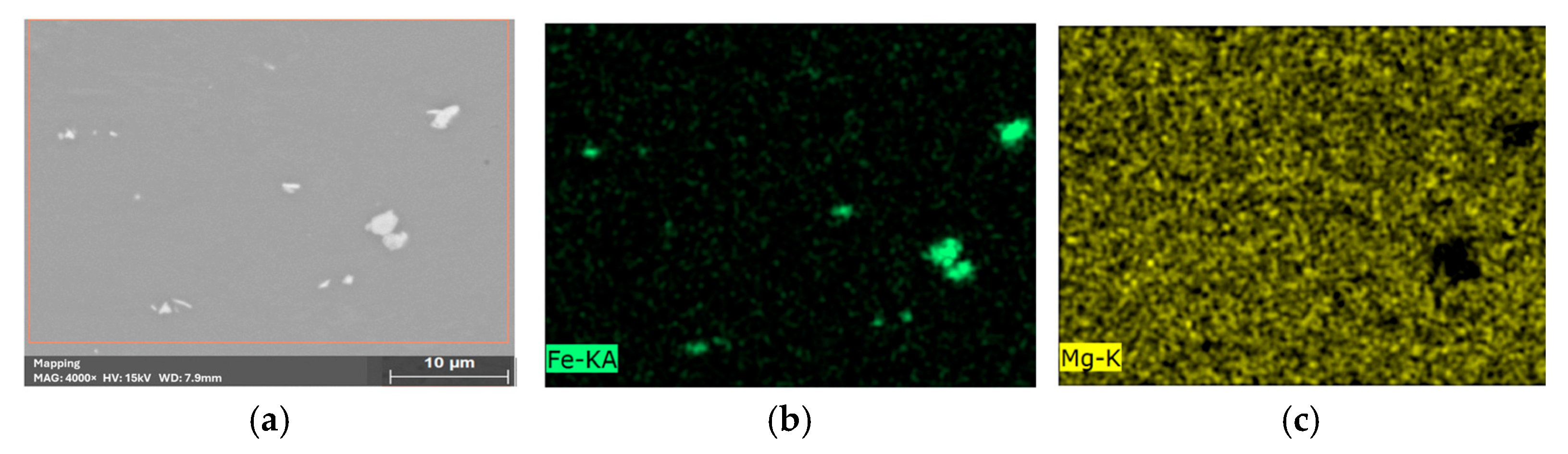
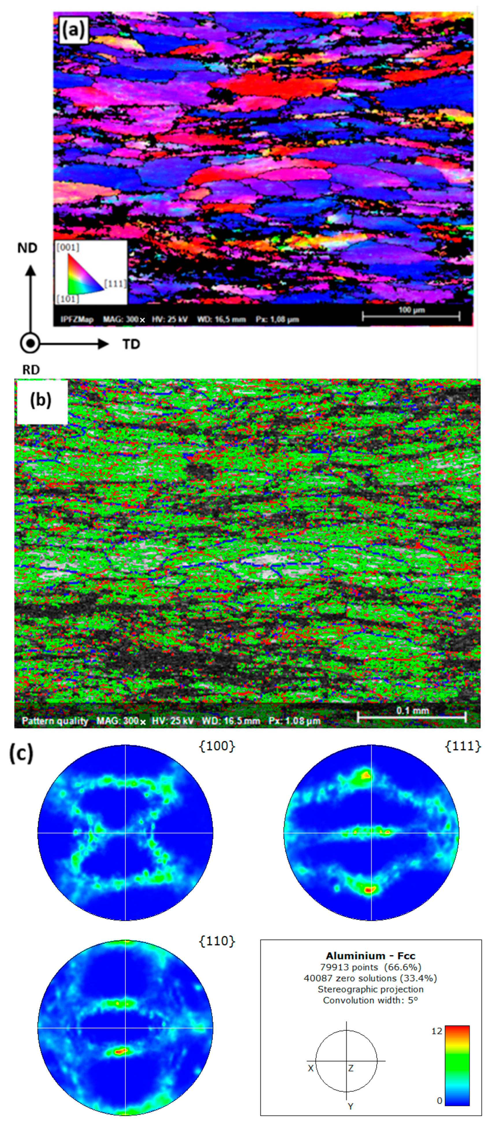
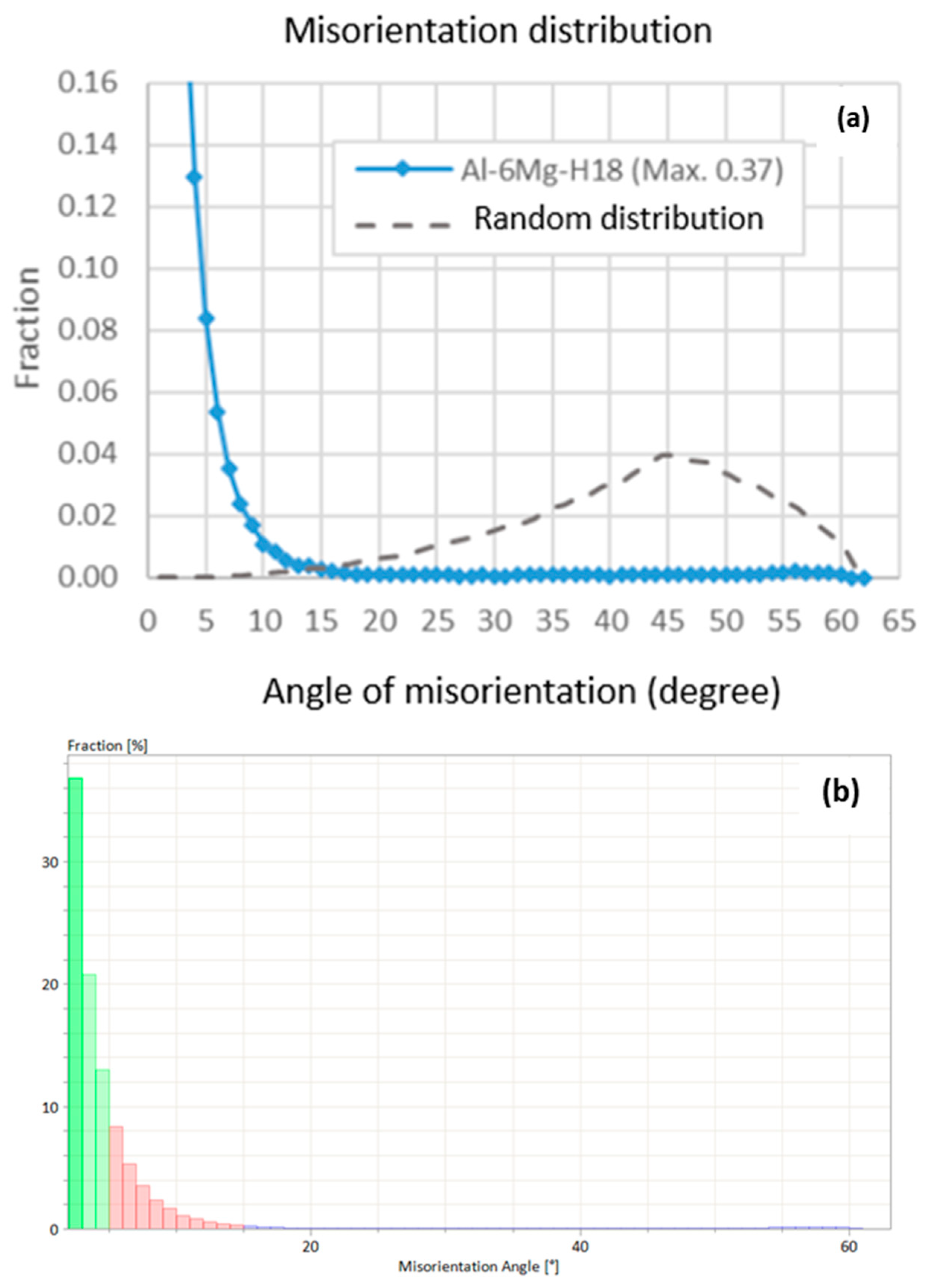
3.3.1. Base Material

The chemical analysis revealed the presence of 6.09 wt. % magnesium, as well as small amounts of Ti, Si, Fe, and Zn elements. Previous work by Polmear and Sargant [31] demonstrated that the addition of a small amount of a third element like Zn accelerates the precipitation kinetics in Al-Mg alloys and increases the maximum achievable hardness during aging. A study by Guo et al. [32] also showed that, in an Al-Mg alloy, optimal aging (8 h at 210 °C) can result in an increase of approximately 20 HV compared to the solution-treated condition. However, after only 1 h of aging, the increase is minimal (<5 HV).
This data supports the informed assumption that, in the alloy studied in this project, the effect of aging caused by the FSW thermal cycle will be negligible due to the short duration at high temperature (1–2 min). Moreover, if fine precipitates were initially present due to natural aging, they are expected to dissolve (or shrink) during heating, without significant coarsening during cooling.
Additionally, the EDS analysis presented in Figure 6 did not reveal the presence of Mg-containing particles. However, such particles could exist at the nanoscale. This aspect will not be further analyzed in this study due to its limited impact on mechanical properties, as reported by Poznak et al. [33]. On the other hand, coarse particles (~1–4 μm) containing iron were observed, as shown in Figure 6.
Figure 7 shows the EBSD map of the base material, which was acquired perpendicular to the rolling direction. It must be noted that the base material has undergone a 75% thickness reduction without any tempering treatment after cold working. As a result, the inverse pole figure (IPF) map in Figure 7a shows an elongated microstructure (54 µm average size) and a strong orientation in the direction [111]. In addition, a high density of low-angle grain boundaries (LAGBs) with a 2- to 5-degree (green) and a 5- to 15-degree (red) misorientation of the subgrains is observed in Figure 7b. The high-angle gain boundaries (HAGBs) with misorientation angles higher than 15 degrees are shown in blue. The high texture of the base metal is highlighted in Figure 8a, in comparison to the random distribution of a non-deformed metal, as reported by J.K. Mackenzie [34]. The misorientation distribution of the LAGB of the presented area in Figure 7 is as high as 95.14% in the presented map, because of the applied cold-working conditions (Figure 8b). However, due to the high strain hardening, about 25% of the pixels of the EBSD map remain non-resolved (with the boundary lengths of 53.8 mm, 18.7 mm, and 3.7 mm for the 2–5 deg., the 5–15 deg., and the 15–62.8 deg. of misorientation angles, respectively). HAGBs adjacent to the unindexed regions are not considered in this calculation in order not to artificially create HAGBs that would lead to an overestimation of the absolute LAGB fraction.

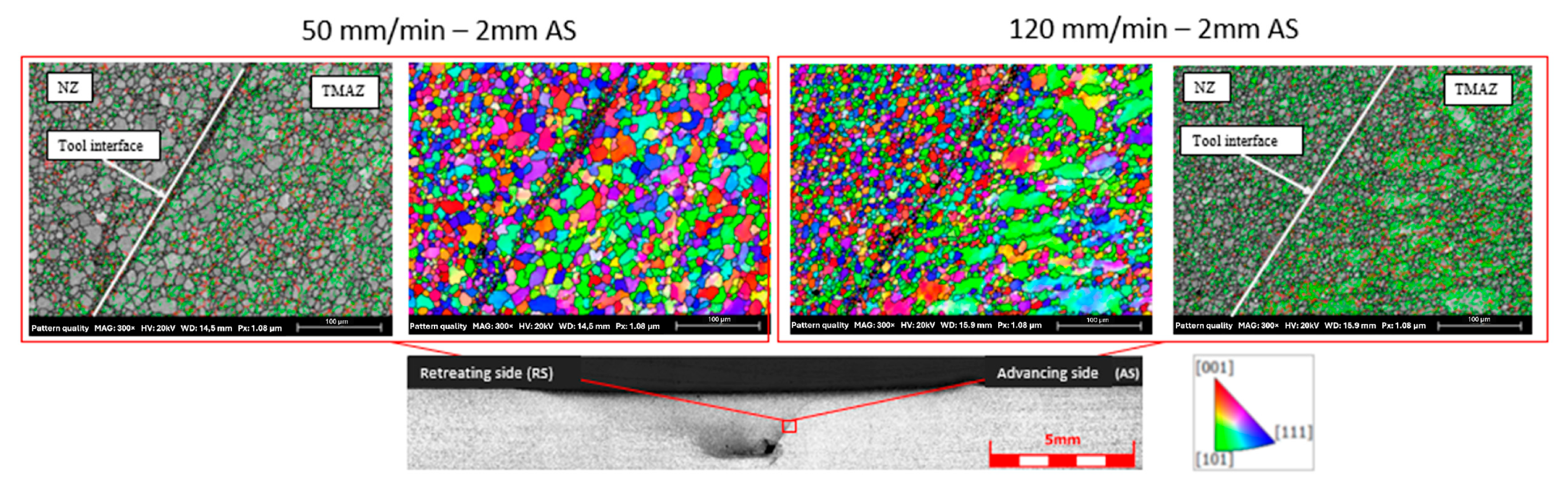
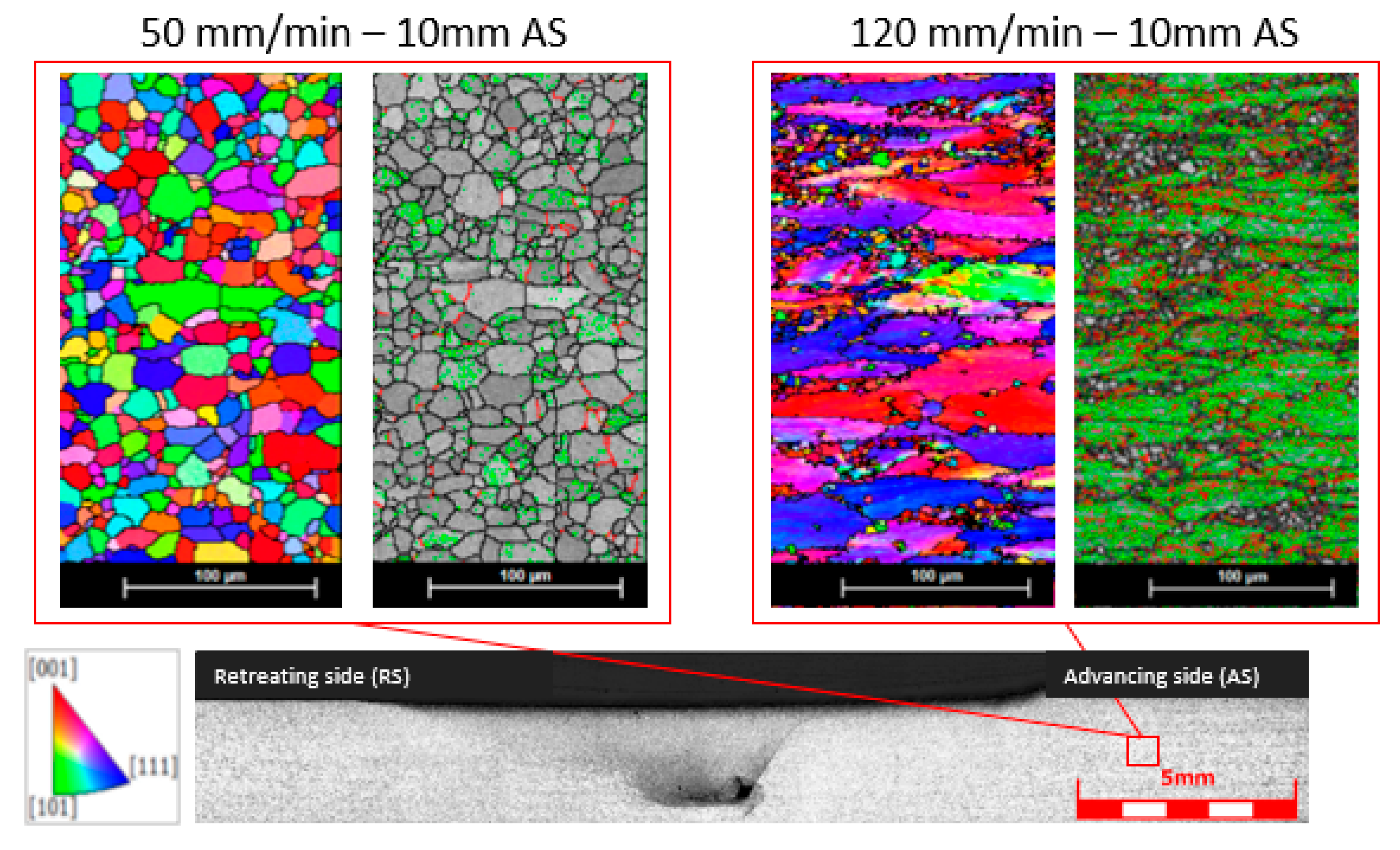
3.3.2. Influence of Travel Speed on the Microstructure

1.
Nugget zones
Figure 9 shows the EBSD maps obtained from the upper and the lower nugget zones. The microstructures of both zones exhibit recrystallized equiaxed grains, with some grains containing a significant presence of subgrains (the green and red lines in Figure 9b,d). According to Gourdet and Montheillet [35], this finding highlights the fact that these locations have undergone continuous dynamic recrystallization (CDRX). The effect of the travel speed on the distribution of grain size can be seen in Figure 10. The average grain size for the travel speed of 50 mm/min in the LNZ (5.9 µm) is slightly smaller than that in the UNZ (8.9 µm). Similar differences were observed for the travel speed of 120 mm/min, where the average grain size was 4.1 µm for the LNZ and 7.8 µm for the UNZ.
The difference in grain size between the LNZ and the UNZ can be explained by the fact that the UNZ experiences intense plastic deformation, as confirmed by the LAGB fraction being more significant in the UNZ in comparison with the LNZ; this more significant plastic deformation is due to direct tool interaction, causing dynamic recrystallization. However, the material in direct contact with the rotating tool shoulder in this zone undergoes a higher amount of frictional heat and consequently a longer exposure to high temperature, which allows the grains to grow.
Overall, the equiaxed grain size is smaller for the travel speed of 120 mm/min because there is less heat input in this case compared to 50 mm/min. It decreases from 8.9 µm at 50 mm/min to 7.8 µm at 120 mm/min in the UN zone, and from 5.9 µm to 4.1 µm in the LN zone, representing decreases of approximately 12% and 30%, respectively, in the UN and the LN zones. At high traverse speeds, the tool remains in contact with the material at each location for a shorter time, leading to a decreased heat input, which then results in limited grain growth. The opposite occurs at low traverse speeds.
A summary of all the above findings is presented in Table 2. The relationship between travel speed and heat input was previously studied and quantified by Song et al. [36] for an ultralight Mg–Li alloy. Their study showed that the temperature in the processing area increases with higher rotation speeds and decreases with increasing travel speeds, which is in agreement with our findings in the studied Al-Mg alloy.
2.
Thermo-mechanically affected zones (TMAZ)
  • Advancing side (AS)
Figure 11 shows the transition zone between the end of the nugget zone (NZ) and the beginning of the TMAZ. For the travel speed of 50 mm/min, recrystallized grains are observed on both sides of the tool interface, while elongated grains are observed for the travel speed of 120 mm/min. In both travel speeds, the TMAZ experiences moderate plastic deformation and lower temperature compared to NZ, leading to a limited breakdown of the existing grain structure and subgrain formation, hence the higher LAGB fraction values in this zone. At 120 mm/min travel speed, the grains in this region tend to be elongated. This tendency is not observable at 50 mm/min because of the higher generated heat in the latter case in comparison to 120 mm/min.
It is interesting to note that, for the high travel speed, the grains in IPF Z are mostly oriented in the [101] direction, while they are in the [111] direction for the base material in the same IPF, which could be attributable to the shear deformation due to tool movement, as the shear stress causes grains to bend and rotate, changing their original orientation. Similar findings have been reported with FSWed 5xxx and 6xxx aluminum alloys [37,38,39,40]. Nevertheless, in the present case, the transition between the NZ and the TMAZ is more abrupt, most likely due to the geometry of the FSP tool. In addition to the above findings, the fraction of LAGB shows a 22% increase from the travel speed of 50 mm/min to 120 mm/min, as reported in Table 3.
  • Retreating side (RS)
Figure 12 shows that, similar to the advancing side, the retreating side for the travel speed of 50 mm/min is also a recrystallized area, while for the travel speed of 120 mm/min, the former grains still exist with a fraction less than that of the AS, although they are mostly oriented in the [101] direction in IPF Z, as discussed in the case of the AS. However, in contrast to the advancing side, the tool interface is not visible, which can be due to the sluggish deformation conditions in the retreating side, as also reported in [41]. Table 4 and Table 5 shows that the grain sizes for both travel speeds are similar in the RS, and the difference between the two travel speeds for LAGB is around 14%.
  • Heat-affected zone
Figure 13 highlights the effect of the travel speed on the microstructure of the advancing side in the heat-affected zone. The equiaxed recrystallized grains are dominant at the travel speed of 50 mm/min, while only some grains have undergone recrystallization at the travel speed of 120 mm/min. Also, subgrain density is smaller for the lower travel speed compared to the higher travel one, where grains containing significant amounts of sub-boundaries are predominant. The extensive presence of subgrain boundaries at the higher generated temperatures led to significant recrystallization of the original grains. It appears that the generated heat at the travel speed of 50 mm/min is sufficient to produce static recrystallization even without any additional deformation. With the travel speed of 120 mm/min, the grains are still oriented in the [111] direction. The above finding has important practical implications for the industrial application of the FSP process to this alloy. It is also important to note that, as shown in Table 6, the LAGB remains twice as high when using the higher travel speed, and the grain size becomes approximately 55% smaller for the lower travel speed.
Kalinenko et al. [30,42] evaluated the influence of friction stir welding (FSW) under high heat-input conditions on microstructural evolution, and similar findings regarding the different zones were reported in two separate studies.

3.4. Mechanical Properties

Figure 14 highlights the location of the SPTests, which were conducted using a punch with a diameter of 1 mm. Figure 15 shows the results of the SPTests conducted for the investigated travel speeds. These curves were obtained using Equation (1) [43].
Τ = P 2 π r a v g t
where T is the shear stress (MPa), P is the load (N), ravg is the average radius between punch radius and die radius (mm), and t is the specimen thickness (mm).
At the center (0 mm), the results show similarity between both curves of the FSP, even though the ultimate shear stress at the travel speed of 120 mm/min shows a slight increase of 8 MPa. This increase is likely attributable to a finer grain structure in the nugget zone (NZ) at the higher travel speed. At 2 mm from the center of the FSP, the shear stress curves for both travel speeds are almost similar. However, in the case of the 50 mm/min travel speed, differences are observed between the AS and the RS, which are likely due to non-recrystallized original grains. At both 10 and 20 mm from the center of the FSP, the curve profiles begin to diverge more distinctly, with the 120 mm/min speed exhibiting higher stiffness and elevated stress levels compared to the 50 mm/min speed. This could be explained in terms of the LAGB percentage distribution. This observation is further supported by microhardness measurements and microstructural characterization, both of which reveal differences between the AS and RS at the same travel speed.
To better contextualize these mechanical responses, the data in Figure 15 should be interpreted alongside the LAGB distributions summarized in Table 2, Table 3, Table 4 and Table 5 and visualized in Figure 16. Figure 17 systematically correlates the evolution of the LAGB fraction with the SPT results, and a reasonably good correlation with an R2 of 0.85 is obtained. This integrated analysis offers a clearer understanding of how substructural changes influence mechanical performance. This finding could be interpreted in terms of the influence of the starting material state on the evolution of the subgrain boundaries. The original grains of the base material in a high LAGB zone are more elongated and oriented in the rolling direction. Thus, the fact that the FSP was performed on cold-worked plate material has an effect on the non-uniformity of the microstructure. In addition, in comparison to no-strain hardened materials, where the LAGB fraction rises within the friction zones [44], the present study highlights the fact that the LAGB fraction is lower in the friction zones in comparison to the base material, due to the higher dislocation density in the base material. Therefore, under these conditions, travel speed has a significant effect on the extent of recrystallization of the friction zones and will affect the mechanical properties of the FSPed regions.

4. Conclusions

The influence of friction stir processing on an aluminium-6% magnesium-H18 alloy was investigated by examining microstructure, microhardness, and in situ shear properties at room temperature for two different travel speeds. The following conclusions can be drawn from this study:
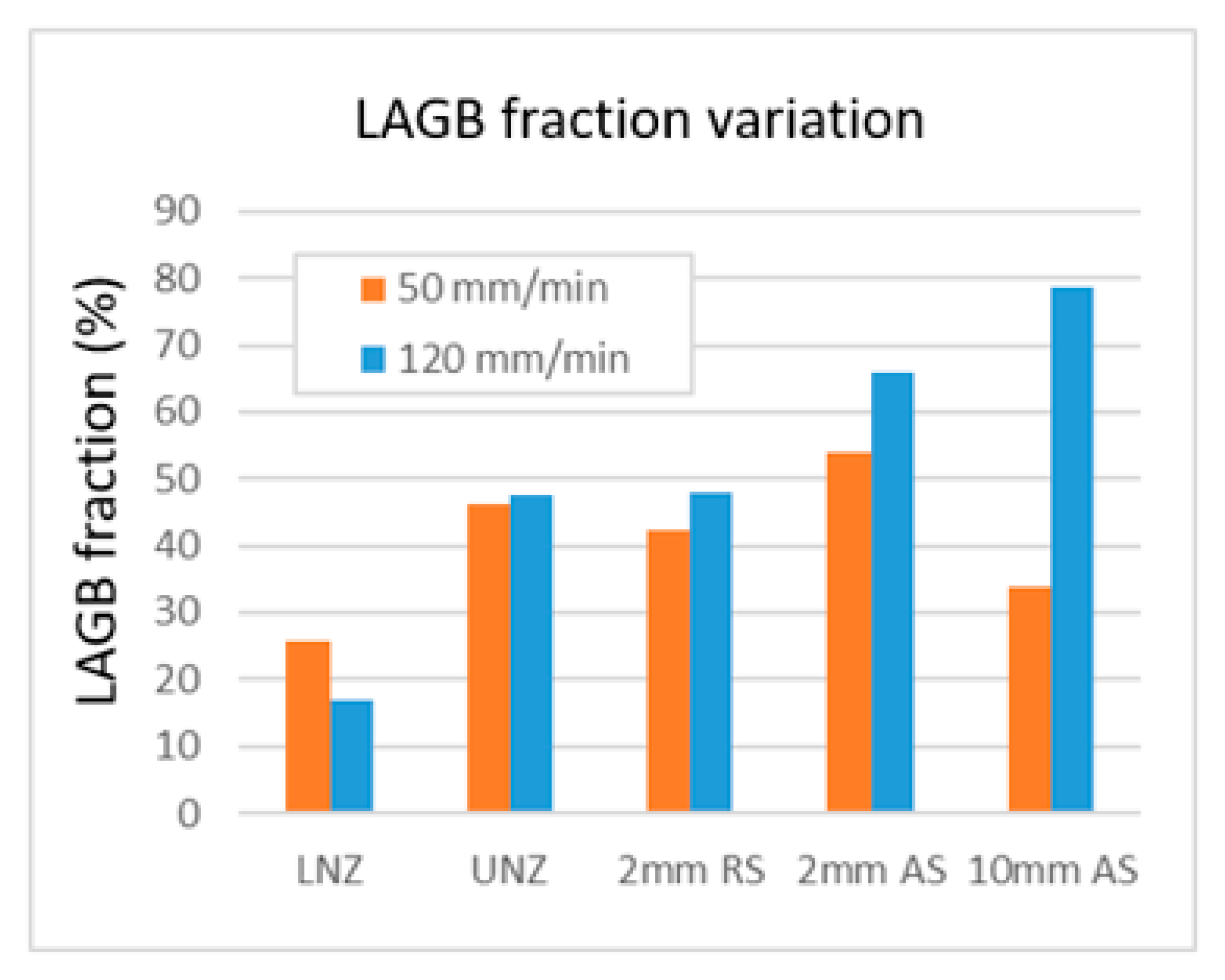
  • Travel speed significantly impacts the microstructure of different regions of FSPed material, including the nugget zone (NZ), thermo-mechanically affected zone (TMAZ), and heat-affected zone (HAZ). Travel speed influences heat input, material flow, and, consequently, grain size.
  • In the nugget zone (NZ), and as a consequence of the material stirring and the heat input, the FSP leads to grain refinement at both travel speeds. However, at the lower travel speed of 50 mm/min, the action of the higher heat input induces a slight increase in the grain size compared to 120 mm/min. EBSD analysis showed that continuous dynamic recrystallization occurs in both the upper (UNZ) and the lower nugget zones (LNZ). However, the grain size in the LNZ is slightly lower than that in the UNZ.
  • At the lower travel speed (50 mm/min), the combination of significant hardening and higher temperatures compared to the 120 mm/min travel speed results in recrystallization. In contrast, elongated grains were widely observed at the higher travel speed of 120 mm/min. SPT conducted in different locations revealed similarities in the center of the FSP for both travel speeds. However, at 2 mm from the nugget zone, differences were observed between the AS and the RS, which are related to the presence of non-recrystallized original grains.
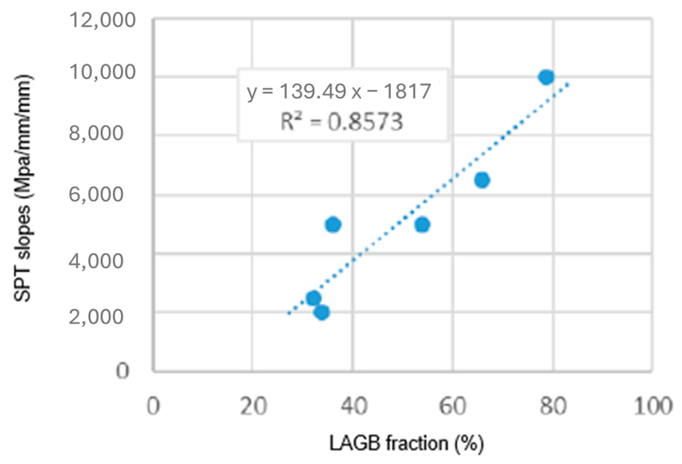
  • A linear correlation between the SPT slope and LAGB fraction can be assumed.

Author Contributions

Conceptualization, M.J. and P.G.; Methodology, M.J., P.G., S.M.C. and M.S.; Validation, S.M.C., M.S., N.A. and M.J.; Formal analysis, M.J., P.G., S.M.C., M.S. and N.A.; Investigation, P.G. and M.J.; Resources, M.J.; Data Curation, M.J., S.M.C., M.S. and N.A.; Writing—Original Draft Preparation, S.M.C.; Writing—Review and Editing, S.M.C., M.J., M.S. and N.A.; Supervision, M.J.; Project Administration, M.J. All authors have read and agreed to the published version of the manuscript.

Funding

This research received no external funding.

Data Availability Statement

The raw data supporting the conclusions of this article will be made available by the authors on request.

Conflicts of Interest

The authors declare no conflicts of interest.

References

  1. Cheng, W.; Liu, C.Y.; Huang, H.F.; Zhang, L.; Zhang, B.; Shi, L. High strength and ductility of Al–Si–Mg alloys fabricated by deformation and heat treatment. Mater. Charact. 2021, 178, 111278. [Google Scholar] [CrossRef]
  2. Wang, J.T.; Liu, A.X.; Zhang, Y.K.; Xie, L.; He, M.T.; Luo, K.Y. Influence of Process Parameters on Wear Resistance of Surfaces Modified by Friction Stirring Processing in 7075 Aluminum Alloy. Met. Mater. Int. 2025, 31, 625–635. [Google Scholar] [CrossRef]
  3. Rohim, M.N.M.; Abdullah, M.E.; Mohammed, M.M.; Kubit, A.; Aghajani Derazkola, H. Friction Stir Processed AA5754-Al2O3 Nanocomposite: A Study on Tribological Characteristics. J. Compos. Sci. 2024, 8, 216. [Google Scholar] [CrossRef]
  4. Prabhakar, D.A.P.; Arun Kumar Shettigar, A.; Mervin, A.; Herbert, M.A.; Manjunath Patel, G.C.; Pimenov, D.Y.; Giasin, K.; Prakash, C. A comprehensive review of friction stir techniques in structural materials and alloys: Challenges and trends. J. Mater. Res. Technol. 2022, 20, 3025–3060. [Google Scholar] [CrossRef]
  5. Gao, K.; Zhang, Z.; Wang, G.; Sun, X.; Zhang, Y. Enhancing metallurgical and mechanical properties of friction stir lap welding of aluminum alloys by microstructure reconstruction. Sci. Rep. 2024, 14, 31987. [Google Scholar] [CrossRef]
  6. Dhairiyasamy, R.; Gabiriel, D.; Kandasamy, M.; Rajendran, S. Investigation of Microstructural and Mechanical Characteristics of Friction Stir Welded Aluminum Alloy 7075-t6. Trans. Indian Inst. Met. 2024, 77, 3789–3797. [Google Scholar] [CrossRef]
  7. Kolagotla, R.K.; Krishna, B.V.; Bhargavi, P.; Janaki, D.V.; Babu, B.R.; Babu, M.V.; Satyanarayana, M.V.; Naresh, G. Toward Achieving Grain Refinement in Al2014 Alloy Through Multi-pass FSP: Microstructure and Mechanical Behavior. J. Inst. Eng. India Ser. D 2024, 1–10. [Google Scholar] [CrossRef]
  8. Heidarzadeh, A.; Javidani, M.; Mofarrehi, M.; Farzaneh, A.; Chen, X.-G. Submerged Dissimilar Friction Stir Welding of AA6061 and AA7075 Aluminum Alloys: Microstructure Characterization and Mechanical Property. Metals 2021, 11, 1592. [Google Scholar] [CrossRef]
  9. Chang, I.; Du, X.H.; Huang, J.C. Achieving ultrafine grain size in Mg–Al–Zn alloy by friction stir processing. Scr. Mater. 2007, 57, 209–212. [Google Scholar]
  10. Zheng, Z.; Li, Q.; Chen, X.; Gao, A.; Zhang, N. Application Status and Prospects of Friction Stir Processing in Wrought Magnesium Alloys: A Review. Trans. Indian Inst. Met. 2024, 77, 1891–1906. [Google Scholar] [CrossRef]
  11. Xu, N.; Qiu, Z.; Gu, B.; Liu, Z.; Zhu, S.; Song, Q.; Wang, D.; Shen, J. Enhanced mechanical properties of thermo-mechanically affected zone of friction-stir welded AZ61 magnesium alloy joint. Mater. Res. Technol. 2024, 30, 3594–3601. [Google Scholar] [CrossRef]
  12. Heidarzadeh, A.; Mohammadzadeh, R.; Jafarian, H.R.; Pruncu, C.I.; Simar, A. Role of geometrically necessary dislocations on mechanical properties of friction stir welded single-phase copper with medium stacking fault energy. J. Mater. Res. Technol. 2022, 16, 194–200. [Google Scholar] [CrossRef]
  13. Chen, M.; Chang, Z.; Li, H.; Tao, H.; Jiang, B.; Li, Z.; Zhang, H. The microstructure evolution and mechanical properties of multi-layer friction stir additive manufacturing for T2 copper. Mater. Today Commun. 2024, 42, 111213. [Google Scholar] [CrossRef]
  14. Kalashnikova, T.; Cheremnov, A.; Eliseev, A.; Gurianov, D.; Knyazhev, E.; Moskvichev, E.; Beloborodov, V.; Chumaevskii, A.; Zykova, A.; Kalashnikov, K. Structural Changes in Block-Shaped WEBAM’ed Ti6Al4V Samples after Friction Stir Processing. Lubricants 2022, 10, 349. [Google Scholar] [CrossRef]
  15. Regev, M.; Almoznino, B.; Spigarelli, S. A Study of the Metallurgical and Mechanical Properties of Friction-Stir-Welded Pure Titanium. Metals 2023, 13, 524. [Google Scholar] [CrossRef]
  16. Zykova, A.; Vorontsov, A.; Chumaevskii, A.; Gurianov, D.; Savchenko, N.; Gusarova, A.; Kolubaev, E.; Tarasov, S. In Situ Intermetallics-Reinforced Composite Prepared Using Multi-Pass Friction Stir Processing of Copper Powder on a Ti6Al4V Alloy. Materials 2022, 15, 2428. [Google Scholar] [CrossRef]
  17. Mironov, S.; Sato, Y.S.; Kokawa, H.; Hirano, S.; Pilchak, A.L.; Semiatin, S.L. Microstructural Characterization of Friction-Stir Processed Ti-6Al-4V. Metals 2020, 10, 976. [Google Scholar] [CrossRef]
  18. Kim, J.Y.; Jung, W.S.; Lee, W.S.; Byeon, J.W. Surface modification of cast Inconel 740 superalloy by heat-assisted friction stir processing. Met. Mater. Int. 2016, 22, 694–699. [Google Scholar] [CrossRef]
  19. Patel, V.; Li, W.; Vairis, A.; Badheka, V. Recent Development in Friction Stir Processing as a Solid-State Grain Refinement Technique: Microstructural Evolution and Property Enhancement. Crit. Rev. Solid State Mater. Sci. 2019, 44, 378–426. [Google Scholar] [CrossRef]
  20. Guduru, R.K.; Darling, K.A.; Kishore, R.; Scattergood, R.O.; Koch, C.C.; Murty, K.L. Evaluation of mechanical properties using shear–punch testing. Mater. Sci. Eng. A 2005, 395, 307–314. [Google Scholar] [CrossRef]
  21. Fall, A.; Monajatia, H.; Khodabandehb, A.; Fesharakib, M.H.; Champliaud, H.; Jahazi, M. Local mechanical properties, microstructure, and microtexture in friction stir welded Ti-6Al-4V alloy. Mater. Sci. Eng. A 2005, 749, 166–175. [Google Scholar] [CrossRef]
  22. Sajadifar, S.V.; Scharifi, E.; Weidig, U.; Steinhoff, K.; Niendorf, T. Effect of Tool Temperature on Mechanical Properties and Microstructure of Thermo-Mechanically Processed AA6082 and AA7075 Aluminum Alloys. HTM J. Heat Treatm. Mat. 2020, 75, 177–191. [Google Scholar] [CrossRef]
  23. Sahraoui, T.; Hadji, M.; Bacha, N.; Badji, R. Superplastic Deformation Behavior of 7075 Aluminum Alloy. J. Mater. Eng. Perform. 2003, 12, 398–401. [Google Scholar] [CrossRef]
  24. Kumar, N.; Jayaganthan, R.; Brokmeier, H.-G. Effect of deformation temperature on precipitation, microstructural evolution, mechanical and corrosion behavior of 6082 Al alloy. Trans. Non-Ferr. Met. Soc. China 2017, 27, 475–492. [Google Scholar] [CrossRef]
  25. Monajati, H.; Zoghlami, M.; Tongne, A.; Jahazi, M. Assessing Microstructure-Local Mechanical Properties in Friction Stir Welded 6082-T6 Aluminum Alloy. Metals 2020, 10, 1244. [Google Scholar] [CrossRef]
  26. ASTM E8/E8M-06a; Standard Test Methods for Tension Testing of Metallic Materials. ASTM International: West Conshohocken, PA, USA, 2006.
  27. Nakamura, T.; Obikawa, T.; Nishizaki, I.; Enomoto, M.; Zhenglong, F. Friction Stir Welding of Non-Heat-Treatable High-Strength Alloy 5083-O. Metals 2018, 8, 208. [Google Scholar] [CrossRef]
  28. Fujii, H.; Cui, L.; Maeda, M.; Nogi, K. Effect of tool shape on mechanical properties and microstructure of friction stir welded aluminum alloys. Mater. Sci. Eng. A 2006, 419, 25–31. [Google Scholar] [CrossRef]
  29. Wang, Y.; Jiang, H.; Wu, X.; Meng, Q. Microstructure and Mechanical Property Evolution of Robotic Friction Stir-Welded Al–Li Alloys. Crystals 2023, 13, 582. [Google Scholar] [CrossRef]
  30. Kalinenko, A.; Dolzhenko, P.; Malopheyev, S.; Yuzbekova, D.; Shishov, I.; Mishin, V.; Mironov, S.; Kaibyshev, R. Grain Structure Evolution in 6013 Aluminum Alloy during High Heat-Input Friction-Stir Welding. Materials 2023, 16, 5973. [Google Scholar] [CrossRef]
  31. Polmear, I.J.; Sargant, K.R. Enhanced age-hardening in aluminium-magnesium alloys. Nature 1963, 200, 669–670. [Google Scholar] [CrossRef]
  32. Guo, C.; Zhang, H.; Zou, J.; Li, B.; Cui, J. Effects of pre-treatment combining with aging on the microstructures and mechanical properties of Al-Mg-Ag alloys. Mater. Sci. Eng. A 2019, 740–741, 82–91. [Google Scholar] [CrossRef]
  33. Poznak, A.; Freiberg, D.; Sanders, P. Chapter 10—Automotive Wrought Aluminium Alloys. In Fundamentals of Aluminium Metallurgy; Dans, R.N.L., Ed.; Woodhead Publishing: Cambridge, UK, 2018; pp. 333–386. [Google Scholar] [CrossRef]
  34. Mackenzie, J.K. Second paper on statistics associated with the random disorientation of cubes. Biometrika 1958, 45, 229–240. [Google Scholar] [CrossRef]
  35. Gourdet, S.; Montheillet, F. An experimental study of the recrystallization mechanism during hot deformation of aluminium. Mater. Sci. Eng. A 2000, 283, 274–288. [Google Scholar] [CrossRef]
  36. Song, W.; Wu, Z.; He, S.; Liu, J.; Yang, G.; Liu, Y.; Jin, H.; He, Y.; Heng, Z. Effects of Friction Stir Processing on the Microstructure and Mechanical Properties of an Ultralight Mg-Li Alloy. Crystals 2024, 14, 64. [Google Scholar] [CrossRef]
  37. Fonda, R.W.; Bingert, J.F.; Colligan, K.J. Development of grain structure during friction stir welding. Scr. Mater. 2004, 51, 243–248. [Google Scholar] [CrossRef]
  38. Jones, M.J.; Heurtier, P.; Desrayaud, C.; Montheillet, F.; Allehaux, D.; Driver, J.H. Correlation between microstructure and microhardness in a friction stir welded 2024 aluminium alloy. Scr. Mater. 2005, 52, 693–697. [Google Scholar] [CrossRef]
  39. Nourani, M.; Milani, A.S.; Yannacopoulos, S. On experimental optimization of friction stir welding of aluminum 6061: Understanding processing-microstructure-property relations. Int. J. Adv. Manuf. Technol. 2015, 79, 1425–1441. [Google Scholar] [CrossRef]
  40. Bin, W.; Bo-Bo, L.; Jia-Xiang, Z.; Quan, F.; Liang, W.; Deng, W. EBSD study on microstructure and texture of friction stir welded AA5052-O and AA6061-T6 dissimilar joint. Mater. Des. 2015, 87, 593–599. [Google Scholar]
  41. Xiea, G.M.; Cuia, H.B.; Luoa, Z.A.; Misrab, R.D.K.; Wang, G.D. Asymmetric distribution of microstructure and impact toughness in stir zone during friction stir processed a high strength pipeline steel. Mater. Sci. Eng. A 2017, 704, 401–404. [Google Scholar] [CrossRef]
  42. Kalinenko, A.; Dolzhenko, P.; Malopheyev, S.; Shishov, I.; Mishin, V.; Mironov, S.; Kaibyshev, R. Microstructural Evolution and Material Flow during Friction Stir Welding of 6013 Aluminum Alloy Studied by the Stop-Action Technique. Metals 2023, 13, 1342. [Google Scholar] [CrossRef]
  43. Lucas, G.E. The development of small specimen mechanical test techniques. J. Nucl. Mater. 1983, 117, 327–339. [Google Scholar] [CrossRef]
  44. Li, Y.; Guan, Y.; Liu, Y.; Zhai, J.; Hu, K.; Lin, J. Effect of processing parameters on the microstructure and tensile properties of a dualphase MgeLi alloy during friction stir processing. J. Mater. Res. Technol. 2022, 17, 2714–2724. [Google Scholar] [CrossRef]
Figure 1. Sampling location for the performed tests.
Metals 15 00709 g001
Figure 2. Shear-punch setup and schematic of the punch fixture.
Metals 15 00709 g002
Figure 3. Global views of the FSPed regions in Aluminium-6% magnesium samples with travel speeds of (a) 120 and (b) 50 mm/min.
Metals 15 00709 g003
Figure 4. Vickers microhardness evolution as a function of travel speed (a) 50 mm/min and (b) 120 mm/min.
Metals 15 00709 g004
Figure 5. Vickers microhardness map (2D) for both travel speeds, (a) 50 mm/min and (b) 120 mm/min (HAZ: heat-affected zone, TMAZ: thermo-mechanically affected zone, UNZ: upper nugget zone, and LNZ: lower nugget zone).
Metals 15 00709 g005
Figure 6. EDS mapping of the base metal.
Metals 15 00709 g006
Figure 7. EBSD: (a) IPF map (RD is the rolling direction grain orientation map), (b) boundary map, and (c) the pole figure perpendicular to the rolling direction of the Al-6Mg base material.
Metals 15 00709 g007
Figure 8. Misorientation distribution in the Al-6Mg base material. Comparison to the random distribution (a), Distribution of percentages as a function of the misorientation angle (b).
Metals 15 00709 g008
Figure 9. EBSD maps of the upper nugget zone (UNZ) on the retreating side (a,b) and advancing side (c,d), and of the lower nugget zone (LNZ) on the retreating side (e,f) and advancing side (g,h).
Metals 15 00709 g009
Figure 10. Cumulative grain size distributions in the UNZ (a) and in the LNZ (b).
Metals 15 00709 g010
Figure 11. EBSD maps of the advancing side at 2 mm from the center of the FSPed region.
Metals 15 00709 g011
Figure 12. EBSD maps in the retreating side at 2 mm from the stir processing location center.
Metals 15 00709 g012
Figure 13. EBSD maps of the advancing side at 10 mm from the center of the FSP nugget zone.
Metals 15 00709 g013
Figure 14. Locations of the conducted SPT.
Metals 15 00709 g014
Figure 15. SPT curves at 0 mm (a), 2 mm (b), 10 mm (c), and 20 mm (d) from the FSP nugget.
Metals 15 00709 g015
Figure 16. Variation of the LAGB fraction in the FSPed material.
Metals 15 00709 g016
Figure 17. LAGB effect on SPT curve slopes.
Metals 15 00709 g017
Table 1. Chemical composition (wt. %) of the aluminium used in the experiment.
AlMgTiFeSiZnMnBCu
Bal.6.090.0750.0710.0580.0330.0270.00120.0006
Table 2. Mechanical properties of the base metal.
UTS (MPa)YS 0.2%A%
372.5 ± 0.22307.5 ± 3.538.55 ± 0.1
Table 3. Grain sizes and LAGB fractions for the two travel speeds.
Travel SpeedsZonesLAGB Fraction (%)Grain Size (μm)
50 mm/minUNZ46.38.9
LNZ25.75.9
120 mm/minUNZ47.67.8
LNZ16.84.1
Table 4. Grain sizes and LAGB fraction for both travel speeds in the TMAZ (AS).
Travel SpeedZoneLAGB Fraction (%)Grain Size (μm)
50 mm/minTMAZ5417.5
120 mm/minTMAZ65.919.9
Table 5. Grain sizes and LAGB fraction for both travel speeds in the TMAZ (RS).
Travel SpeedZoneLAGB Fraction (%)Grain Size (μm)
50 mm/minTMAZ42.211.8
120 mm/minTMAZ48.111.8
Table 6. Grain sizes and LAGB fractions for the two travel speeds in the HAZ.
Travel SpeedZoneLAGB Fraction (%)Grain Size (μm)
50 mm/minHAZ33.716.6
120 mm/minHAZ78.625.8
Disclaimer/Publisher’s Note: The statements, opinions and data contained in all publications are solely those of the individual author(s) and contributor(s) and not of MDPI and/or the editor(s). MDPI and/or the editor(s) disclaim responsibility for any injury to people or property resulting from any ideas, methods, instructions or products referred to in the content.

