Article

Effects of Post-Treatment on the Microstructure Evolution and High-Temperature Oxidation Properties of Nickel-Based Superalloys Fabricated by Selective Laser Melting

1
Sino-French Engineer School, Nanjing University of Science and Technology, Xiaolingwei 200, Nanjing 210094, China
2
School of Mechanical Engineering, Nanjing University of Science, Xiaolingwei 200, Nanjing 210094, China
*
Author to whom correspondence should be addressed.
Metals 2025, 15(7), 708; https://doi.org/10.3390/met15070708
Submission received: 28 May 2025 / Revised: 20 June 2025 / Accepted: 23 June 2025 / Published: 26 June 2025
(This article belongs to the Special Issue Research Progress of Crystal in Metallic Materials)

Abstract

This study mainly investigates the high-temperature oxidation properties of GH3230 alloys fabricated by selective laser melting after different heat treatments. The SLM-formed GH3230 samples were subjected to solid-solution treatments at 1100 °C, 1230 °C, and 1320 °C for 30 min, followed by water quenching to room temperature. High-temperature oxidation tests were conducted at 1100 °C for 100 h. The results show that the as-built sample is composed of many columnar grains with cellular dendrites. Many M23C6 carbides are distributed in the interdendritic of the as-built sample. After solid-solution treatment, the dendrite structures completely disappear and the M23C6 carbides are transformed into M6C carbides. The M6C carbides dissolve completely as the solid-solution temperature increases to 1320 °C. The average grain size of GH3230 samples increased gradually with the increase in the solid-solution treatment temperature. However, the degree of recrystallization increased with the heat treatment temperature, leading to the transformation of low-angle grain boundaries into high-angle grain boundaries. A relatively dense oxide film, mainly including Cr2O3 and CrMn2O4, are formed in the GH3230 alloy after high-temperature oxidation. Suitable solid-solution treatment improves the high-temperature oxidation resistance of the GH3230 alloy, and the enhanced oxidation-resistance mechanisms are discussed.

1. Introduction

GH3230 is a nickel-based high-temperature alloy, which achieves solid-solution strengthening through the addition of Cr, Mo, and W, and forms M6C/M23C6 carbides with C to impede dislocation motion [1,2,3]. Therefore, this alloy achieves a tensile strength above 250 MPa at 900 °C along with excellent oxidation resistance, making it widely used in high-temperature components, such as the combustion chambers of aircraft engines [4,5,6].
With the development of aero-engine design and manufacturing technology, the internal structure of an aero-engine combustor becomes more and more complex [7,8]. By using traditional methods, it is difficult to fabricate advanced aero-engine combustors with GH3230 alloy as the main high-temperature structural material [9,10]. In recent years, the selective laser melting (SLM) method was widely used to melt the alloy powder layer by layer according to the 3D slicing model of the part; it provides a new approach for the preparation of the GH3230 alloy with a complex structure. The use of the SLM process can effectively avoid the drawbacks of traditional methods, such as structural defects caused by the multi-step processing of precipitation-hardened materials, and reduced corrosion resistance due to grain boundary segregation in cast microstructures [11].
In recent years, preparing the refractory alloys by forming SLM, especially nickel-based superalloys, has increasingly attracted the attention of scholars [12,13,14,15]. Liu et al. [16] fabricated the Hastelloy 230 superalloy by the SLM process and investigated the effect of SLM process parameters on the microstructure evolution and mechanical properties. The crack formation mechanism and the main strengthening mechanism during the formation of the Hastelloy 230 high-temperature alloy by SLM were discussed, and solidification cracks tend to form when the VED exceeds 100 J/mm3. Tomus et al. [17] investigated the relationship between C content and the crack tendency of the SLM Hastelloy 230 alloy. They pointed out that a low C content could prevent crack formation in the SLM Hastelloy 230 alloy. During the SLM process, under the special solidification conditions of high temperature gradient and high cooling rate, it is easy to obtain fine columnar structures, which have obvious directional solidification characteristics [18], high solid solubility, and high dislocation density. However, the parts formed by SLM have high strength, low plasticity, anisotropic mechanical properties, and a complex distribution of thermal stress, which makes it easy to produce cracks [19]. GH3230 and Hastelloy 230 alloys have a similar elemental composition, so these defects also easily occur during preparation. As a result, most of the SLM-formed parts undergo subsequent heat treatment to eliminate thermal stress, structural homogeneity, and anisotropy of mechanical properties [20,21,22,23]. Solid-solution treatment plays an important role in regulating the properties of the GH3230 alloy. It not only increases the plasticity and improves the anisotropy of mechanical properties, but also controls the microstructure characteristics of the alloy. It can also eliminate thermal stress after heat treatment [15,23].
GH3230 is often used in the combustion chamber of aircraft engines. The inner wall temperature of the aero-engine combustor can reach 1100 °C, and the combustor may overheat for a short time under some extreme flight or test conditions. However, the oxidation behavior of nickel-based high-temperature alloys is mainly concentrated below 1000 °C [24,25,26,27,28]. Therefore, there is a lack of research on the cyclic oxidation behavior of the GH3230 alloy at an extreme service temperature. It is generally believed that the higher the temperature, the more serious the oxidation degree of the alloy. The oxidation kinetics and microstructure of the alloy are not enough to explain the oxidation behavior. The high-temperature oxidation behaviors of the GH3230 alloy processed by SLM are not fully understood at present, especially at high temperatures (>1100 °C) [29]. In this study, the SLM process was used to prepare GH3230 samples, and solid-solution treatment was carried out under various temperatures (1100~1320 °C). This research mainly studied the microstructure characteristics of SLM-processed GH3230 alloys and their high-temperature oxidation behavior under different heat treatment conditions.

2. Experimental Procedure
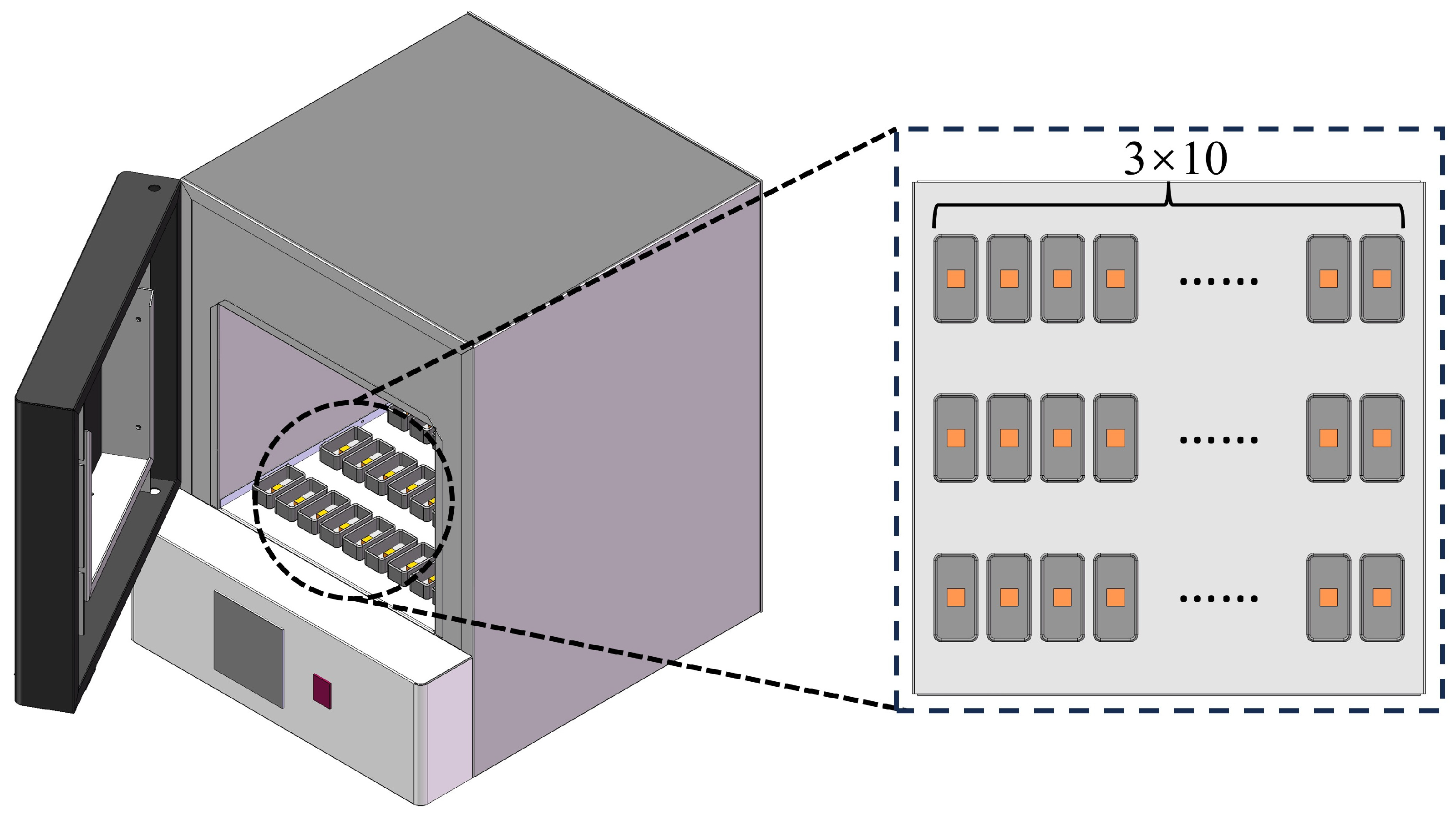
2.1. SLM Process

In this study, the material was commercially available gas-atomized GH3230 powders (purity 99%, particle size: 15~53 μm, Cr 21.76 wt.%, W 14.1 wt.%, Mo 2.01 wt.%, Al 0.26 wt.%, C 0.2 wt.%, Fe 0.54 wt.%, Ni Bal.). GH3230 samples were fabricated by the SLM 125 HL machine (SLM Solutions, Lubeck, Germany), which was equipped with a 400 W Yb: YAG fiber laser. The machine was airtight and fully filled with argon gas during the SLM process. A checkerboard-type laser scanning pattern was utilized. The fabrication was carried out under the conditions that the laser power, the laser scanning speed, the layer thickness, and the hatch distance were 135 W, 0.7 m/s, 50 μm, and 110 μm, respectively. The sample size was 10 mm × 10 mm × 5 mm. The samples built by SLM were labeled as as-built samples.

2.2. Heat Treatment

After being processed by SLM, all samples were immediately treated at different temperatures for solid-solution treatment to study the effect of different temperatures on the carbide precipitation behavior of GH3230 samples. The solid-solution treatment temperature was determined by the existing heat treatment process for cast GH3230 alloy [30]. The temperatures of solid-solution treatment were 1100 °C, 1230 °C, and 1320 °C, maintained for 30 min. After the treatment, all samples were cooled in water to room temperature, as shown in Table 1. The samples treated with a solid solution at 1100 °C, 1230 °C, and 1320 °C, and labeled as HT1, HT2, and HT3, respectively.

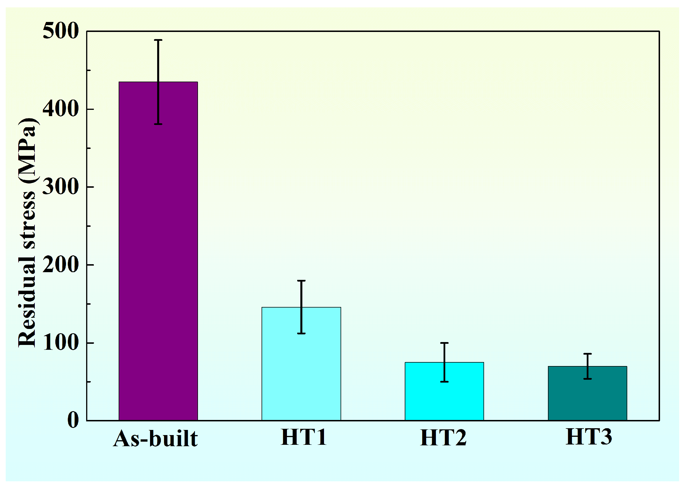
2.3. Residual Stress Test

The X-350A X-ray diffraction stress meter (Aster Stress Technology Co., Ltd., Handan, China) was selected as the testing equipment to systematically measure the residual stress on the samples before and after heat treatment. To ensure the stability of the results, each test point was measured 4 times and the average value was taken. The residual stress tests the oblique fixed Ψ method, with Ψ angles of 0°, 25°, 35°, and 45°, and the peak method cross-correlation method.

2.4. Microstructure Characterization

The microstructural samples were cut via electrical discharge machining in the direction parallel to the SLM building direction. The cut sample blocks were ground with 120 #, 320 #, 600 #, 800 #, 1000 #, 1200 #, 1500 #, and 2000 # sandpapers. Mechanical polishing using metal polishing compounds was carried out to meet the requirements of metallographic samples. Phase identification was conducted by an X-ray diffractometer (XRD) (Bruker D8 AXS Advance, Berlin, Germany) in which a Cu target X-ray tube was used. The parameters were set as follows: wavelength 1.5405 å, tube voltage 36 V, tube current 20 mA, θ angle range 30°~100°, 4°/min scanning speed, and step width 0.02°.
Scanning electron microscopy (SEM) (JSM-7800F, JEOL, Tokyo, Japan) was used to analyze the grain boundary morphology, carbide morphology, and carbide distribution of all samples, in which the working parameters were object distance (10 mm), voltage (15 kV), and electron beam current (8 nA). Nano Measurer1.2 software was used to measure the size and the distribution of the carbides in the corresponding SEM images.
The grain orientation and grain morphology of all samples were analyzed by electron backscatter diffraction (EBSD). The pre-treatment-process EBSD sample’s preparation was similar to that of the OM sample’s preparation, and the samples were electropolished in a solution (90% C2H5OH + 10% HClO4) at 25 V before characterization. The experiment was conducted on a FEI Nova Nano SEM430 instrument (Thermo Fisher Scientific, Waltham, MA, USA) equipped with a Nordlys 2S detector at a step size of 0.25 μm. After scanning, data analysis and post-processing were performed using HKL-Channel5 software (2019 v5.12).

2.5. High-Temperature Oxidation Test

The samples were placed in a muffle furnace and subjected to high-temperature oxidation at 1100 °C for 100 h. There was a total of thirty samples, and three specimens were taken out every 10 h for subsequent testing, as shown in Figure 1.
Before testing, the Al2O3 crucible was dried at 1100 °C and the samples were dried at 80 °C. The total mass of the Al2O3 crucible with samples was measured and labeled as m0. The surface area of each sample was calculated from the sample size and labeled as A. At the beginning of the high-temperature oxidation test, the furnace temperature was raised to the target temperature of 1100 °C, and then the ten crucibles with samples were put into the furnace. After each high-temperature oxidation cycle, remove a crucible with a sample, perform air cooling, and weigh at the end of the 10 cycles. The total mass (m1) of the crucible and sample was measured by electronic balance. The mass gain per unit area (Δm) was calculated using Equation (1). The morphologies of the surface and the cross-section of the oxidation film were observed by SEM.
Δ m = m 1 m 0 A

3. Results

3.1. Residual Stress Analysis

During the SLM process, the high-power laser partially melts a continuous layer of powder. The heat is then transferred to the surrounding material, creating a large temperature gradient [31,32]; this leads to heavy residual stress in the as-built sample. To study the effect of different heat treatments on the internal composition of GH3230 samples, the residual stress in the GH3230 samples before and after solid-solution treatment was measured and shown in Figure 2. The average residual stress of the as-built sample is about 435 MPa. After being treated at 1100 °C, the average residual stress of the HT1 sample decreases to 146 MPa. The residual stress is partly released [33]. In Figure 2, it can be clearly seen that the 1230 °C and 1320 °C solid-solution treatments release most of the residual stress, and the stability tends to a fixed value of 75 MPa. This may be since 1230 °C and 1320 °C reached or even exceeded the recrystallization temperature of the GH3230 alloy. At 1230 °C and 1320 °C, the original columnar grains can be recrystallized. As a consequence, the residual stresses at the grain boundaries are released during recrystallization [34].

3.2. Microstructural Analysis

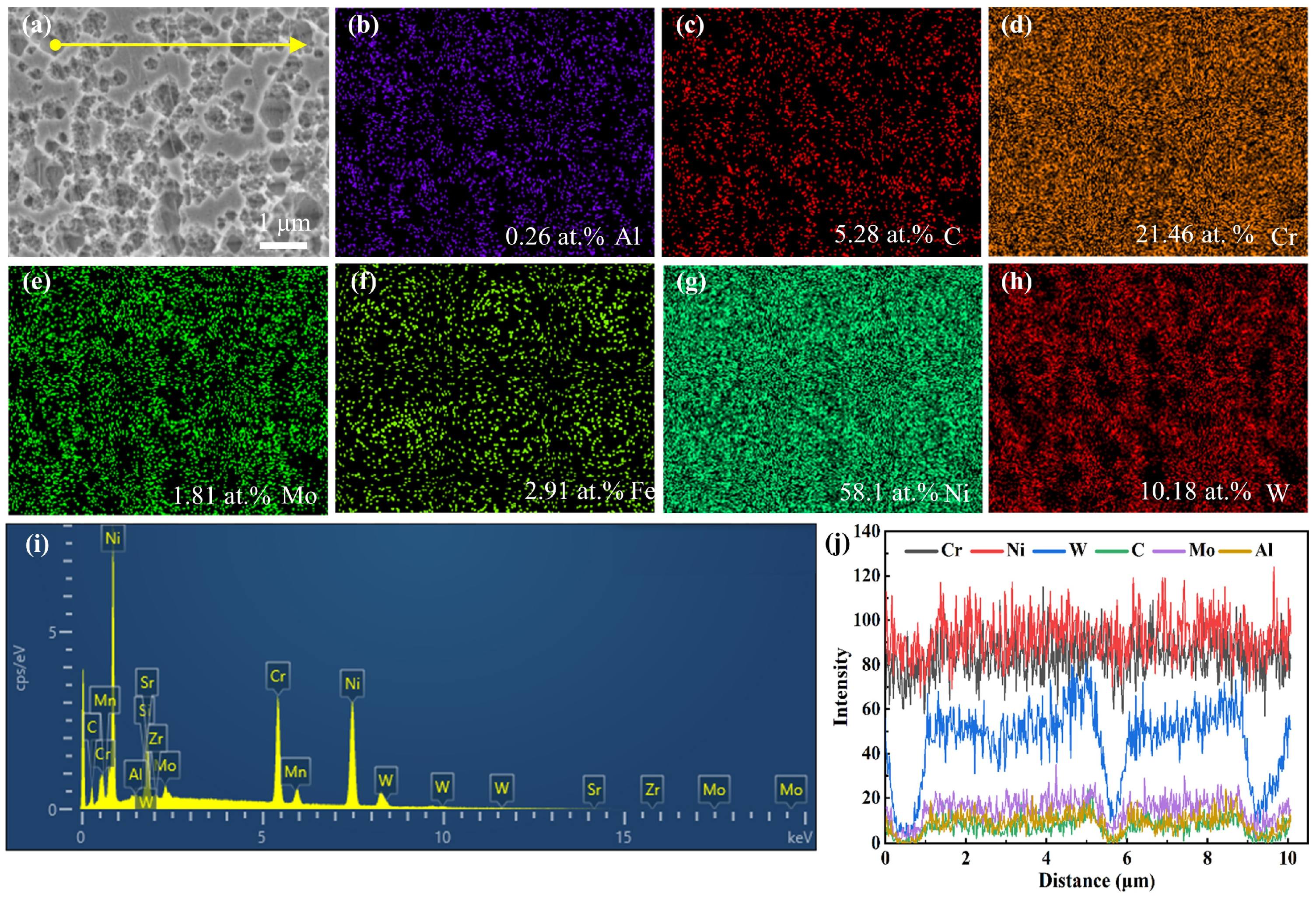
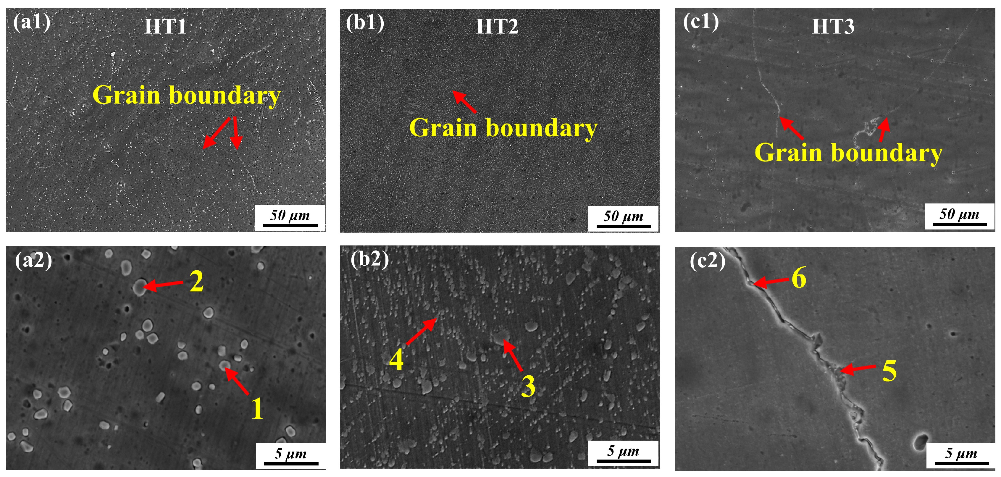
3.2.1. Carbide Precipitation

Figure 3 shows the SEM images of the as-built sample formed by SLM. It can be seen from Figure 3a that the molten pool has a stacked “fish-scale” morphology, which is a typical characteristic of SLM-formed samples. A single melt pool can penetrate two-to-three layers of powder, thereby achieving good metallurgical bonding between adjacent layers. The as-built sample has some defects, such as pores and microcracks. From Figure 3b,c, it can be seen that typical columnar dendrites and cellular dendrites have formed in the as-built sample.
Figure 4 shows the morphology of cellular dendrites under high magnification. From Figure 4b–i, it can be seen that the elements Co, Fe, Cr, and Ni have relatively uniform distributions, with no obvious segregation being observed. Further analysis of the elements reveals that Ni and Cr are present in higher quantities, at 58.1 at. % (Figure 4g) and 21.46 at. % (Figure 4d), respectively. Meanwhile, it can also be seen that Al, C, Mo, and W elements tend to segregate between dendrites, with the mass percentage of the C element being approximately 3.42% (Figure 4c) and that of the W element being approximately 10.18 at. % (Figure 4i).
To further confirm the segregated elements, EDS line scanning was performed on this area, and the results are shown in Figure 4j. The elements Ni and Cr are distributed relatively uniformly, with no obvious segregation. The elements that show segregation are mainly W, Cr, and Mo, according to the EDS scanning results. The segregation of W, Cr, and Mo elements is common in the Ni-base alloy deposited by SLM [35]. Therefore, W, Cr, and Mo will segregate at the cellular dendrite to form M23C6 precipitates during cooling and solidification.
The microstructure of GH3230 alloys under different heat treatment conditions indicates that the choice of heat treatment temperature has a significant effect on the microstructure (Figure 5). When the temperature reaches 1100 °C, it can be noticed in Figure 5(a1) that the molten pool morphology in the HT1 sample completely disappears, and a uniform microstructure with clear grain boundaries is clearly visible. As the temperature increases, the dendrite structures present in the as-built samples also completely dissolve. Some irregular granular precipitates appear at the grain boundaries (Figure 5(a2)). Furthermore, the results of the EDS analysis show that the carbide particles are mainly Mo-rich carbides (M6C) (Table 2), which is often observed in heat-treated Haynes alloys. The M6C carbide is rich in W and Mo. At 710~1030 °C, M6C carbides are formed. M23C6 carbides are formed during solid-solution treatment below 900 °C [36,37,38]. Muhammad et al. [39] found that, at 900 °C, M6C carbides became more discrete after stress relief, which occurred at the grain boundaries of the as-built GH3230 superalloy. M23C6-type carbides stabilize below 956 °C, and M23C6-type carbides convert to M6C-type carbides when heated to above 800 °C. Therefore, the main carbides in the HT1 sample are M6C-type carbides, with an area fraction of 3.71%. Due to the rapid cooling rate, a non-equilibrium structure is still maintained at a high temperature after solid-solution treatment.
The grain morphology and grain size undergo obvious changes (Figure 5(b1)) when the solid-solution temperature reaches 1230 °C. The number of carbides in the grain interiors and the grain boundary of the HT2 sample increase significantly, reaching 15.56% (Figure 5(b2)). When the solid-solution temperature reaches 1320 °C, the grain size of the HT3 sample grows clearly (Figure 5(c1)). As can be seen in Figure 5(c2), most of the carbides disappear and only some small carbides exist at the grain boundary, with an area fraction of only 0.58%. The carbides dissolve into the matrix at a high temperature, so they cannot exert a pinning effect on the grain boundary. The atom migration ability is enhanced at a high temperature, and the grain size of the HT3 sample grows.
Figure 6 presents the statistical results of the size of carbides in the solid-solution-treated samples at different temperatures. When the solid-solution temperature is 1100 °C, the size of the carbides in the HT1 sample is mainly concentrated at 1~1.2 μm, and the area fraction of carbides in this range accounts for 42% of all carbides (Figure 6a). However, as the heat treatment temperature rises to 1230 °C, the column of the histogram moves to the left, and the size of carbides in the HT2 sample decreases clearly (Figure 6b). As is shown in Figure 6b, the ratio of carbides reaches the highest in the range of 0.6~0.8 μm, which accounts for about 40%. To the opposite effect, the ratio of carbides in the range of 0.8~1 μm decreases. Moreover, the column of the histogram for the HT3 sample also continues to shift to the left (Figure 6c). The number of carbides in the HT3 sample accounts for 54%, which is mainly concentrated in the range of 0.2~0.4 μm. All in all, the average carbide sizes of GH3230 alloys at three different heat treatment temperatures (from low to high) are 1.06 μm, 0.65 μm, and 0.47 μm.
Interestingly, the number of carbides in the HT2 sample significantly increases compared with the as-built sample, and the distribution of carbides is more dispersed. However, more carbides dissolve into the matrix when the temperature is raised further from 1230 °C to 1320 °C, and the number of visible carbides is significantly reduced in this case. The M6C carbide is formed by the W and Mo elements in the GH3230 alloy nucleating with C elements. With the continuous diffusion of W and Mo elements, M6C is precipitated. The atomic diffusion capacity is enhanced with the increase in the heat treatment temperature. In this instance, W and Mo elements are enriched in carbon elements. Therefore, more M6C carbides are precipitated at 1230 °C [40]. During solid-solution treatment, the number of carbides is mainly related to the excess content of C element in the sample. As the temperature increases to 1320 °C, the number of carbide precipitates significantly decreases, which may be because the C element, which can form carbides in the GH3230 sample, decreases. At the same time, when the temperature reaches 1320 °C, most of the carbides re-dissolve into the matrix.

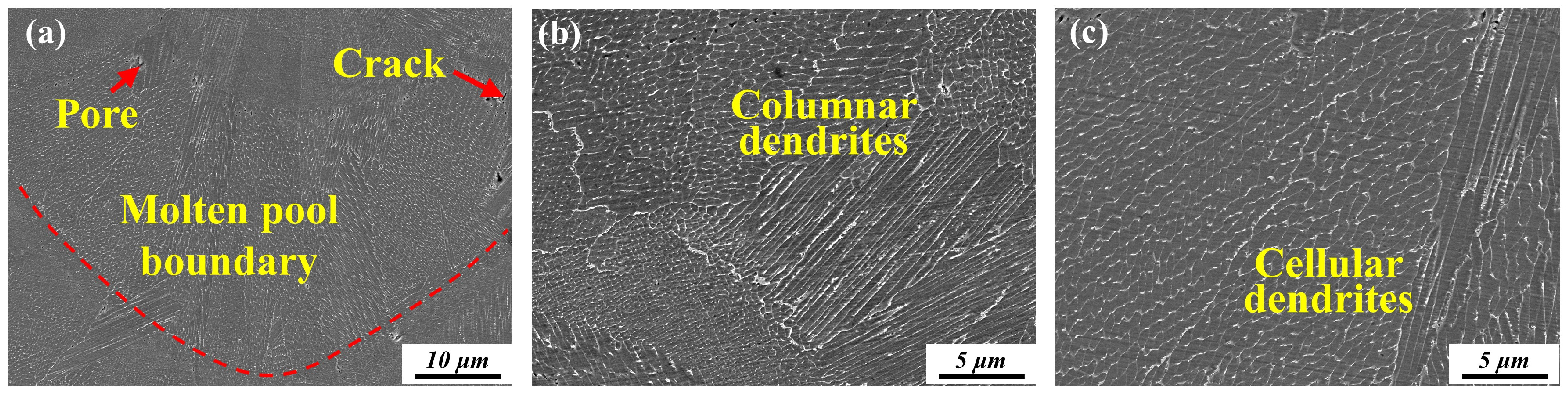
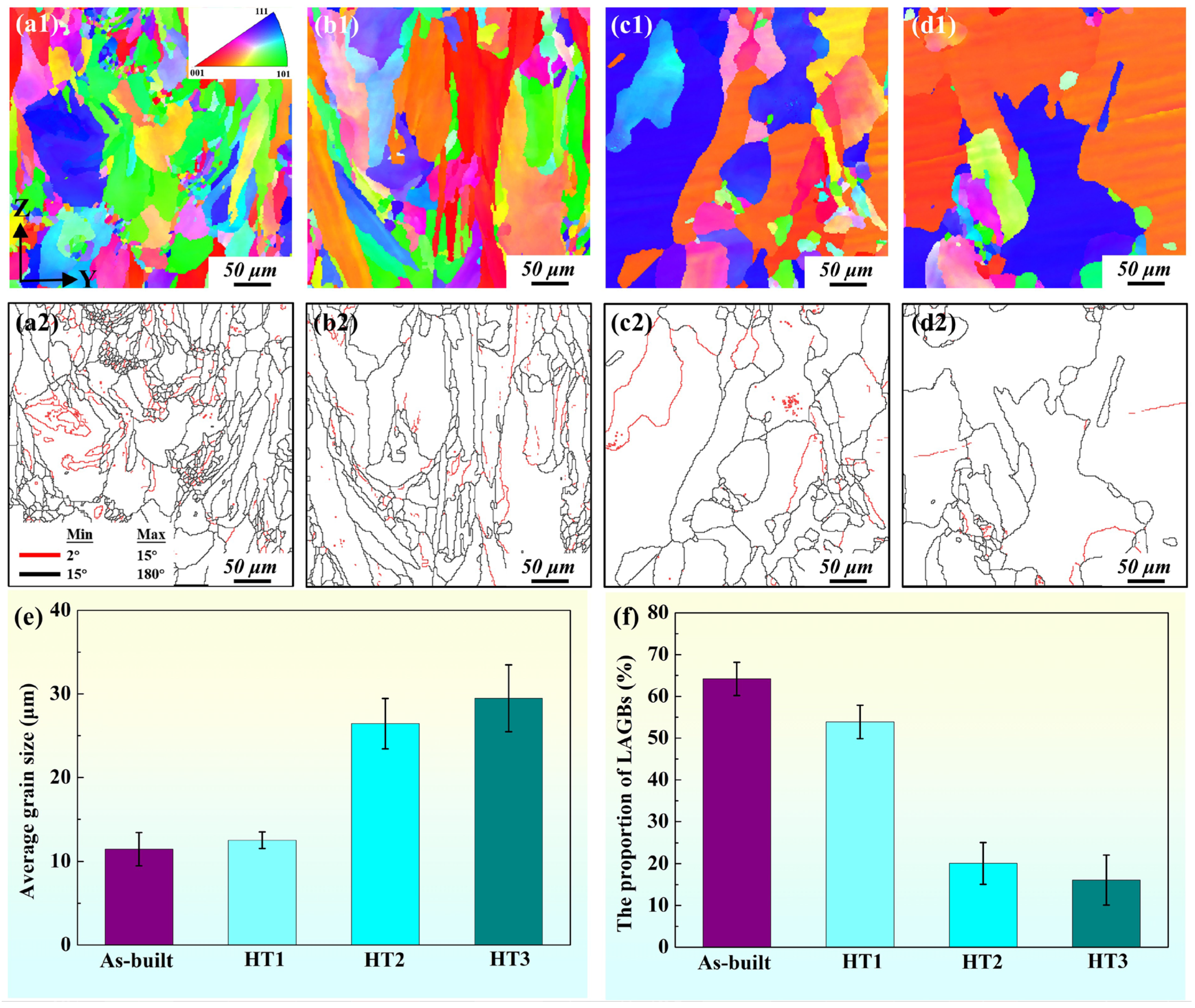
3.2.2. Microstructure

The grain orientations and grain morphologies of all the samples were obtained by EBSD. The inverse pole figure (IPF) EBSD maps of all samples along the building direction are shown in Figure 7. It is worth noting that the X-Y plane is the building platform plane and the Z-axis is parallel to the building direction. As the grains grow along the building direction, a fish-scale molten pool is observed in the Y-Z plane of the as-built sample (Figure 7(a1)). Obvious anisotropy columnar grains, which grow across multiple deposition layers, can be clearly observed in the as-built sample. According to the Euler triangle legend in Figure 7(a1), a relatively strong <101> crystallographic direction along the building direction is detected in the as-built sample shown by the dominant green color.
After solid-solution treatment at 1100 °C, the fish-scale molten pool disappears. However, the columnar grains are still visible in the HT1 sample (Figure 7(b1)). The grain morphology and grain orientation remain unchanged, which indicates that recrystallization does not occur in the HT1 sample. When the solid-solution temperature increases to 1230 °C and 1320 °C, many equiaxed grains can be observed, as shown in Figure 7(c1,d1). The grain morphologies of the HT2 and HT3 samples become regular and uniform compared with the grain morphology of the HT1 sample. In addition, some lamellar twins appear in the HT2 and HT3 samples, which are common structures of recrystallized and annealed, low-stacking fault-energy cubic metals [41]. However, it is worth noting that the grain orientation in the cross-sections of the HT2 and HT3 samples is random, which indicates that grain recrystallization occurs when the temperature reaches 1230 °C.
The average grain size of the as-built sample is 11.47 μm (Figure 7e). Due to rapid, directional, solidification and the high thermal gradient along the building direction, the primary grains are elongated columnar grains. After heat treatment at 1100 °C (HT1), the grain size increases only slightly to 12.54 μm (Figure 7e), and the grain morphology remains largely unchanged, indicating that recrystallization does not occur in this condition. The average grain sizes of the HT2 and HT3 samples are 26.45 μm and 29.48 μm, respectively (Figure 7e). This is attributed to the onset of static recrystallization, driven by the high thermal activation and the release of residual stresses and dislocation densities accumulated during the SLM process.
The grain boundary distributions of the four samples are presented in Figure 7(a2–d2). The number of low-angle grain boundaries (LAGBs, <15°) of the as-built sample accounts for 64.2% (Figure 7f). These LAGBs are formed by dislocation rearrangements [42,43]. The proportions of LAGBs in the HT1, HT2, and HT3 samples are 53.9%, 20.1%, and 16.1%, respectively (Figure 7f). It can be observed that, after solid-solution treatment at 1100 °C, no significant changes occur in the number of misorientation angles, and the number of LAGBs decreases slightly. After the HT2 and HT3 samples are treated, the number of high-angle grain boundaries (HAGBs, >15°) increases significantly. This indicates that grain recrystallization occurs in these two samples [44].

3.3. High-Temperature Oxidation Performance Analysis

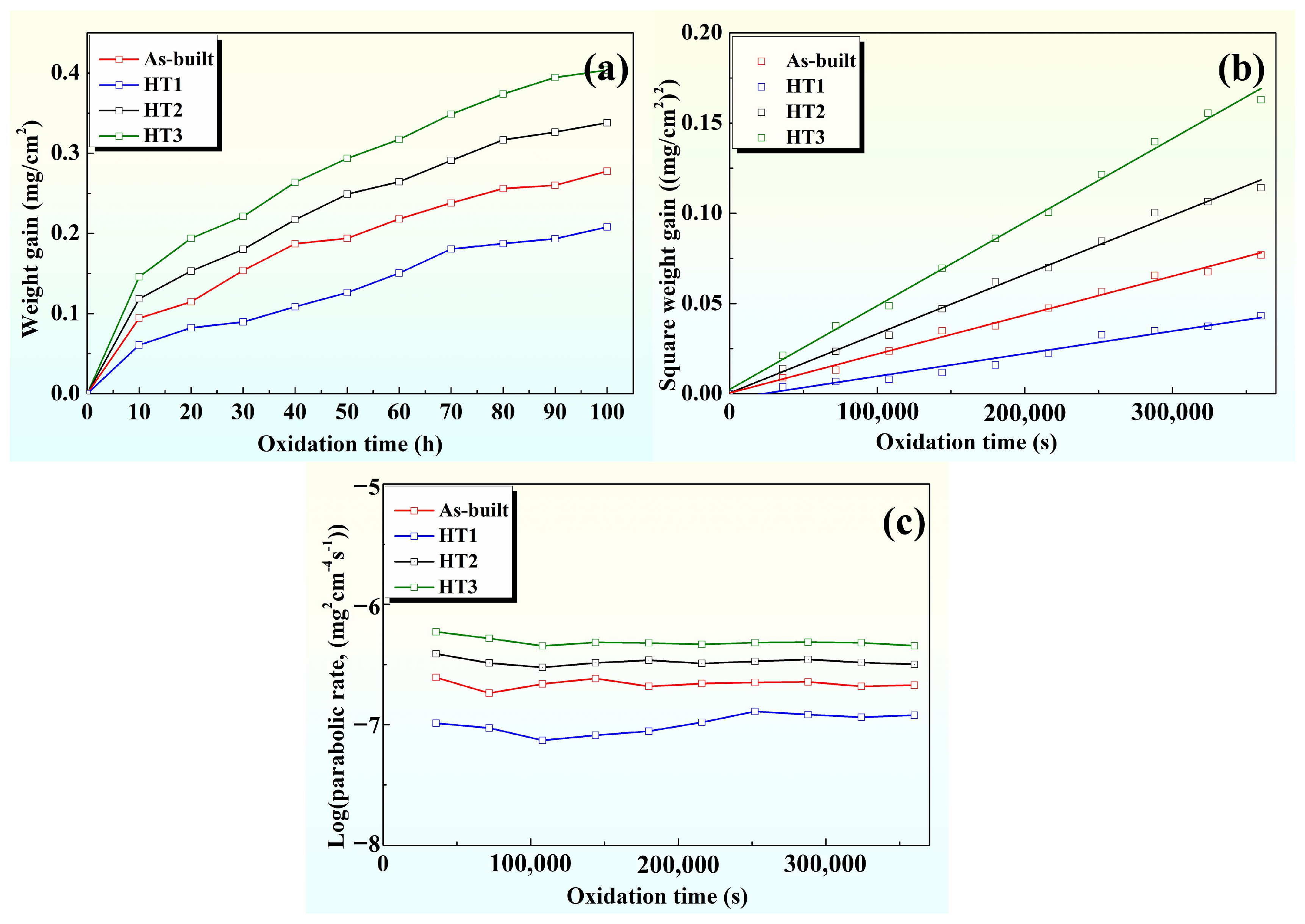
3.3.1. High-Temperature Oxidation Kinetics

Figure 8a shows the weight gain curves of the GH3230 alloy’s oxidation at 1100 °C. The weight gain values of four types of GH3230 alloy samples with different microstructures after high-temperature oxidation at 1100 °C are compared. After high-temperature oxidation for 100 h, the weight gain values of the as-built, HT1, HT2, and HT3 samples are 0.2774 mg/cm2, 0.2080 mg/cm2, 0.3379 mg/cm2, and 0.4038 mg/cm2, respectively. The weight gain of the HT1 samples is the lowest. For HT1 samples, the weight gain after high-temperature oxidation at 1100 °C for 100 h is about 25.6% lower than as-built samples (Figure 8a). After high-temperature oxidation, the weight gain of all samples exhibits a typical parabolic dependence on the oxidation time (Figure 8a). This indicates that the formation of the oxide layer on the GH3230 alloy’s surface is mainly controlled by diffusion at 1100 °C. The oxidation mass gain of all samples is expressed in Equation (2) [45].
( Δ m ) 2 = k p t
where Δm is the weight gain per unit area (mg/cm2), kp is the parabolic rate constant (mg2/cm4 s), and t is the oxidation time (s). Figure 8b shows the relationship between (△m)2 and t during the oxidation of the GH3230 alloy at 1100 °C for all samples. The kp values of the as-built, HT1, HT2, and HT3 samples oxidized at 1100 °C are 2.1599 × 10⁻⁷ mg2/cm4 s, 1.2524 × 10⁻⁷ mg2/cm4 s, 3.2804 × 10⁻⁷ mg2/cm4 s, and 4.6344 × 10⁻⁷ mg2/cm4 s, respectively. The kp value of the HT1 sample is the lowest, which is 42.0% lower than that of the as-built sample. At 1100 °C, the kp value of all samples is stable at the beginning and the end of the oxidation process (Figure 8c). It can be seen from Figure 8a that, during the initial oxidation event, the weight gain of all samples increases rapidly due to the rapid growth of transient oxides. Subsequently, the formation of a protective oxide layer gradually slows down the oxidation rate. The oxidation weight gain and kp value of the HT1 sample are the lowest, which indicates that the HT1 sample, after heat treatment, forms a thin oxidation protective layer and has the greatest anti-oxidation ability.

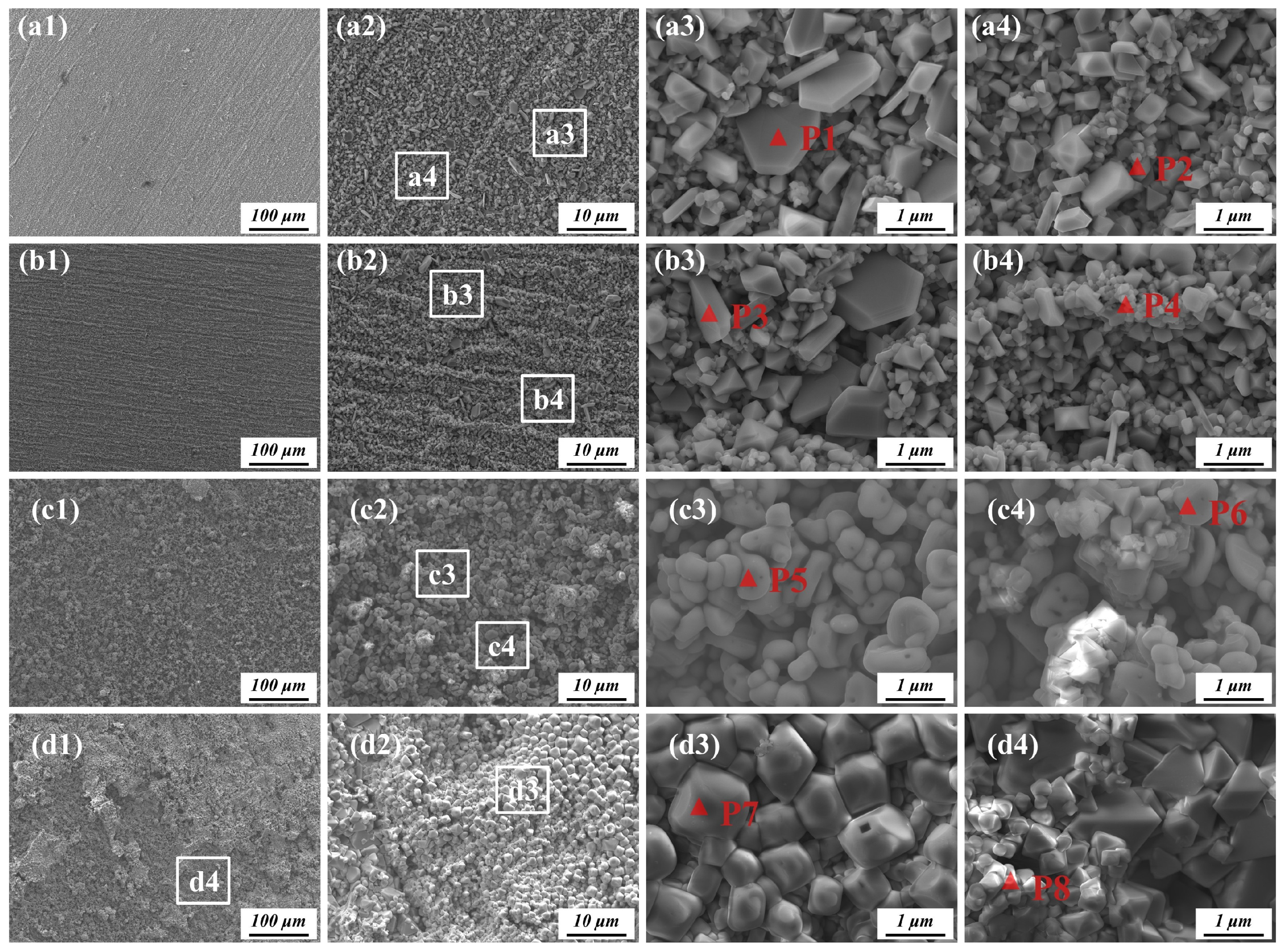
3.3.2. Surface Oxidation Products

Figure 9a–c show the XRD results from the surface of GH3230 samples oxidized at 1100 °C for different times. It can be seen that the surface diffraction peaks of all samples are mainly Cr2O3, Mn3O4, MnCr2O4, and the Ni matrix. In the early oxidation stage, obvious Ni matrix peaks can be seen in all samples (Figure 9a). With the oxidation time prolonged to 60 h, the Ni matrix peak weakens clearly, which shows that, with the prolonged oxidation time, the thickness of the oxide film increases and the densification improves. The intensity of the diffraction peak of MnCr2O4 gradually increases while that of Cr2O3 gradually decreases, showing that MnCr2O4 grows on the top of the Cr2O3 oxide (Figure 9b). When the oxidation time is extended to 100 h, the GH3230 alloy forms the same kind of oxide film. Cr2O3 and MnCr2O4 present the main diffraction peaks on the surface of the HT3 sample (Figure 9c).
Figure 10 shows the surface morphology of all samples after oxidation at 1100 °C for 100 h. As can be seen from Figure 10(a1), a relatively dense oxide film has formed on the surface of the as-built sample, and the oxide film is intact, without shedding. At a high magnification, large, granular oxides can be seen on the oxide film’s surface in the as-built sample (Figure 10(a2)). Figure 10(a3,a4) are local magnifications of the rectangular region (a3) and (a4) in Figure 10(a2). The EDS analysis of point P1 shows that the large oxides mainly contain O and Cr (Table 2). According to the proportion of elements, it is inferred that the oxides are mainly Cr2O3. The granular oxides (point P2) mainly contain Cr, O, and Mn, which indicates that the granular oxides are mainly CrMn2O4 (Table 3). This phenomenon can be attributed to the fine cellular dendritic structure and high dislocation density characteristic of SLM-formed GH3230 samples, which enables the rapid and uniform formation of a continuous and adherent oxide layer (CrMn2O4) in the early stage of oxidation. Additionally, the residual compressive stress in the as-built surface layer helps to suppress crack initiation and oxide film spallation during long-term exposure.
After oxidation at 1100 °C for 100 h, a very dense oxide film is formed on the surface of HT1 sample (Figure 10(b1,b2)). A large amount of Cr2O3 and CrMn2O4 is also formed on the surface of the HT1 sample (Figure 10(b3,b4)). Compared with the as-built sample, the number of granular oxides in the HT1 sample increases clearly (Figure 10(b4)). However, the oxide film on the surface of the HT2 sample is relatively loose after high-temperature oxidation at 1100 °C for 100 h (Figure 10(c1)). The oxide film is basically intact without shedding (Figure 10(c2)). At a high magnification, it can be seen that the oxides on the HT2 sample are mainly granular oxides (CrMn2O4 (P5 and P6)). The oxide film on the surface of the HT3 sample is porous and loose, and a large area presenting shedding appears (Figure 10(d1)). It can be seen that the granular oxide (P7) is CrMn2O4, and the size of the granular oxide is larger than that of the other samples (Figure 10(d3)). The shedding area is enlarged, and Cr2O3 oxides are found to be the largest oxides (Figure 10(d4)). The alloy was heat-treated at 1320 °C, causing grain coarsening and a lower dislocation density. This limits Cr and Mn diffusion, delaying the early formation of a protective oxide layer. During oxidation at 1100 °C for 100 h, Cr is preferentially oxidized, producing large amounts of Cr2O3, especially in areas where the oxide film has cracked or spalled. The growth stress from Cr2O3 formation, combined with the poor adhesion of the oxide layer, leads to delamination.

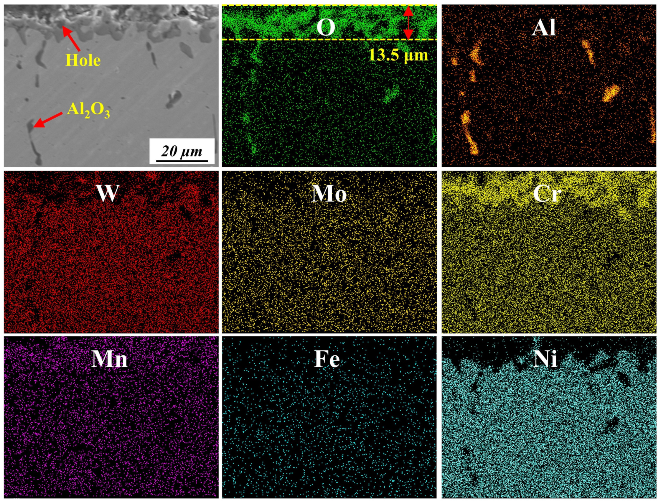
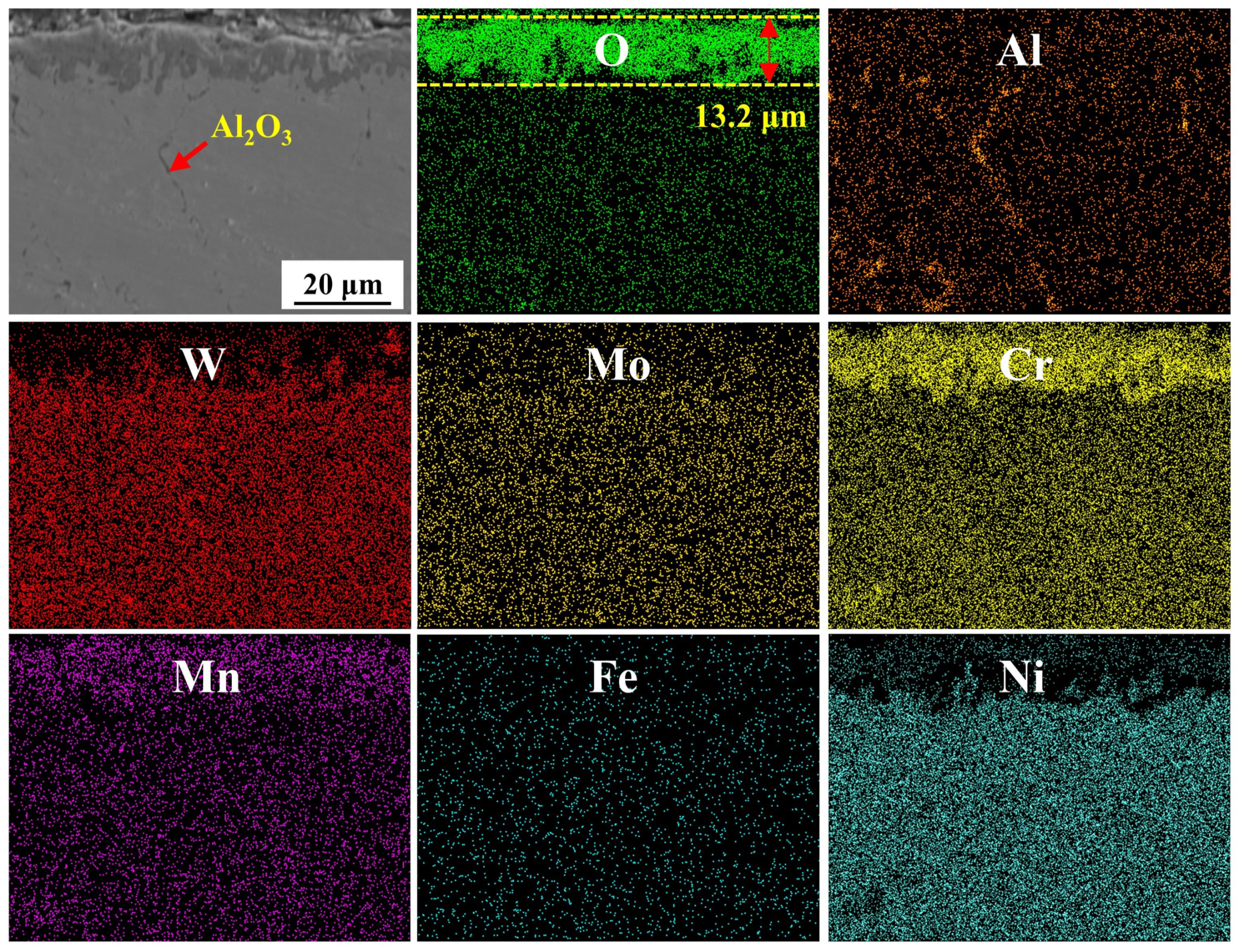
3.3.3. Cross-Sections of Oxidation Products

As can be clearly seen from Figure 11 that a layer of oxide film has formed on the surface of the as-built sample, but the oxide film is relatively loose with some holes. The thickness of the oxide film is 13.5 μm. EDS scanning shows that the oxide film mainly contains Cr, Mn, and O elements. At the same time, it can be seen that the inner part of the as-built sample has been partially oxidized to form Al2O3.
The SEM and EDS images of HT1 samples after high-temperature oxidation at 1100 °C for 100 h are shown in Figure 12. It can be seen that a relatively dense oxide film has formed on the surface of the HT1 sample. The thickness of the oxide film is about 13.2 μm, which is similar to that of the as-built sample. Cr, Mn, and O are still the main elements in the oxide film. In addition, it can be seen that a small amount of Al2O3 oxides appear along the grain boundary in the HT1 sample.
For HT2 samples, the thickness of the rich oxide layer of Cr, Mn, and O is 16.9 μm, which is slightly increased compared with that of the HT1 sample. However, it is worth noting that in the HT2 sample, intragranular oxidation is obvious, and it takes place along the grain boundary (Figure 13). The grain boundary is rich in many Al2O3 oxides. Compared with other samples, the quality of the oxide film of the HT3 sample is the worst. The thickness of the oxide film increases significantly to 29.2 μm (Figure 14). At the same time, there are a lot of holes in the oxide film, and the oxide film is severely broken. Oxidation along the grain boundaries can also be seen.

4. Discussion

4.1. The Influence of Residual Stress and Grain Features on High-Temperature Oxidation

The high-temperature oxidation resistance of the alloy is closely related to the residual stress and grain features of the samples [46,47]. Due to the preferential growth of the grains in the as-built sample, Mn, Cr, and other elements are more easily diffused to the GH3230 alloy’s surface along the preferential direction to react with O. However, the as-built samples have high residual thermal stress. The oxidation resistance of the GH3230 alloy depends on the formation of a dense coating of oxidation products to prevent the oxidation reaction from continuing [48,49]. The diffusion rate of metal cations and oxygen anions through oxidation products increases exponentially with increasing the temperature, and then the growth stress of the oxide film increases.
The higher residual stress and the growth stress of the oxide film in the as-built sample will lead to the cracking and peeling of the oxide film. Therefore, the oxide film of the as-built sample sheds. After heat treatment, the preferred grain growth of the HT1 sample is cancelled. Compared with the as-built sample, the grain size of the HT1 sample does not change a lot, but a high amount of residual thermal stress in the HT1 sample is released, which is beneficial to the formation of a relatively dense oxide film. In the HT2 and HT3 samples, the grain size increases significantly and the dislocations in the samples decrease. Thus, the rapid channel of Cr diffusion is reduced, and the formation of a dense Cr2O3 oxide film is disadvantageous. Therefore, the oxide film on the surface of the HT2 and HT3 samples, especially the HT3 sample, is relatively loose, and the oxide film on the cross-section exhibits the phenomenon of partial shedding.

4.2. The Influence of Carbide Precipitation on High-Temperature Oxidation

Figure 15 provides a schematic of the carbide precipitation behaviors from the solidification process of the SLM to the end of the solid-solution treatment. Due to the different solubility levels of solutes in liquid and solid phases, non-equilibrium solidification and micro-segregation will occur during the SLM process with an ultra-fast cooling rate [50]. During rapid solidification, a high-density dislocation network is formed to adapt to the thermal stress, which effectively traps C atoms and blocks the movement of other atoms. Cr and Mo atoms are heavily segregated on the dislocation network of the as-built sample to form M23C6 nucleation [51].
Solid-solution treatment is helpful to produce a uniform microstructure and control the carbide precipitation of the GH3230 alloy. When the solid-solution temperature is 1100 °C, M23C6 carbides are dissolved, and Cr and Mo are released into the matrix. The diffusion of W, Mo, Cr, and C atoms along their respective concentration gradients is facilitated by the abundance of dislocations present in the as-built sample. In addition, compared to other atoms, C atoms are less soluble in liquid. W and Mo-rich M6C carbides are generally thought to be more stable at a high temperature than Cr-rich M23C6 [52,53]. Consequently, Cr diffuses outward from M23C6 carbides into the matrix, whereas W and Mo in the matrix are segregated toward the precipitation phase, which makes M23C6 transfer to M6C carbides during solid-solution treatment at 1100 °C (Figure 5(a1,a2)).
The size and distribution of carbides are closely related to the solid-solution temperature. Larger carbides hinder the migration of grain boundaries [54]. With the increase in the solid-solution temperature, the driving force of grain boundary migration increases. The carbides dissolve, reducing the size of the carbides. When the solid-solution temperature reaches 1230 °C, part of the grain boundary breaks through the pinning action of carbides and gradually moves away from the carbides. With the increase in the solid-solution temperature, the factors that hinder grain boundary migration are reduced, and the likelihood of recrystallization is increased. The carbides are still nailed to the original grain boundaries, leading to the appearance of carbides within the grains, as shown in Figure 5(b1,b2). The large-diameter solute atoms such as W and Mo in M6C carbides are re-solidified into the matrix, and the carbides are severely decomposed (Figure 5(c1,c2)).
Some studies have shown that the Cr content should exceed 15% to form a continuous Cr2O3 oxide film on the surface of superalloys [55,56]. The Cr content in the GH3230 alloy is about 21.76 wt.%; therefore, at a high temperature, a Cr2O3 oxide film forms on the surface of the GH3230 alloy, which hinders the diffusion of O from diffusing into the matrix further and effectively inhibits the oxidation rate of the GH3230 alloy. Although the affinity of Al to O is higher than that of Cr in the GH3230 alloy, the content of Cr in the GH3230 alloy is much higher than that of Al. Thus, in the initial phase of oxidation, Cr on the GH3230 alloy surface meets O in the air to form Cr2O3, which is due to the outward diffusion velocity of Cr3+ being 2–3 orders-of-magnitude higher than the inward diffusion velocity of O2− [56,57]. A continuous and dense Cr2O3 oxide film is formed on the surface of GH3230 alloy, which is helpful to prevent the diffusion of O2− into the matrix and hinder the further oxidation of the alloy. A little Al2O3 is distributed along the grain boundary at the bottom of the oxide film due to the slight internal oxidation of the matrix.
At the same time, the content of Mn in the GH3230 alloy is about 0.31 wt.%, which is much lower than the content of Cr (21.76 wt.%). At the initial stage of oxidation, Cr reacts with O to form a dense Cr2O3 layer. It is well known that the diffusion of Mn ions in Cr2O3 oxides is orders-of-magnitude faster than that of Cr ions [58,59]. Mn ions diffuse to the surface of the Cr2O3 layer and react with O to form MnO. MnO reacts with Cr2O3 to form MnCr2O4. Jian et al. [60] found that even adding a low percentage of Mn to a binary Fe-Cr alloy could lead to the realization of the MnCr2O4 phase. In addition, it has been found in some studies that a Mn-depleted zone forms in the Haynes 230 alloy after a period of rapid growth of MnCr2O4 at 1000 °C. Due to the limitation of Mn content in the Haynes 230 alloy’s surface layer, the requirement for a continuous supply of Mn may not be met. This Mn depletion may interrupt the growth of MnCr2O4, and then Cr diffusion in the matrix controls the formation of Cr2O3 on MnCr2O4. As a result, two layers of oxides, both internal and external, have been observed in many studies [61,62]. However, in this study, even if the high-temperature oxidation reaches 100 h, there is still no double-layer oxide. It is also proven that the oxidation resistance of the GH3230 alloy is better.

5. Conclusions

In this study, the effects of different heat treatment temperatures on the microstructure and high-temperature oxidation performance of a GH3230 alloy were studied. The main conclusions can be summarized as follows:
(1) A microscopic study reveals columnar grains with cellular dendrites in the as-built sample. Many M23C6 carbides are distributed in the inter-dendritic region. After solid-solution treatment, the dendrite structures completely disappear. The M23C6 carbides dissolve completely.
(2) The average grain size of the GH3230 sample increases gradually with the increase in the solid-solution treatment. With the increase in the heat treatment temperature, the degree of recrystallization increases, leading to the transformation of LAGBs into HAGBs.
(3) The solid-solution treatment temperature has an obvious effect on the size and content of carbides. When the solid-solution temperature is 1230 °C, the content of M6C carbides reaches the maximum value. The average size of carbides decreases from 1.06 μm to 0.47 μm as the solid-solution temperature increases from 1100 °C to 1320 °C.
(4) For HT1 samples, the mass gain after high-temperature oxidation at 1100 °C for 100 h is about 25.6% lower than the as-built samples. The kp values of the HT1 sample are the lowest, which is 42.0% lower than that of the as-built sample.
(5) A relatively dense oxide film, mainly including Cr2O3 and CrMn2O4, forms in the HT1 sample after being treated at 1100 °C for 100 h. A porous and loose oxide film with a thickness of 29.2 μm forms on the surface of the HT3 sample. Grain orientation, grain size, and residual stress all affect the high-temperature oxidation properties of the GH3230 alloy.

Author Contributions

Conceptualization, R.R., Y.Y., D.H., J.F. and C.C.; methodology, R.R. and Y.Y.; software, R.R.; validation, R.R., Y.Y., D.H. and J.F.; formal analysis, R.R.; investigation, R.R.; resources, R.R., Y.Y. and C.C.; data curation, R.R.; writing—original draft preparation, R.R. and Y.Y.; writing—review and editing, R.R., D.H. and J.F.; visualization, R.R.; supervision, Y.Y. and C.C.; project administration, Y.Y. and C.C.; funding acquisition, Y.Y. and C.C. R.R. and Y.Y. contributed equally to this work. All authors have read and agreed to the published version of the manuscript.

Funding

This research was funded by the National Natural Science Foundation of China (grant number 51901101).

Data Availability Statement

The original contributions presented in this study are included in the article. Further inquiries can be directed to the corresponding author.

Conflicts of Interest

The authors declare no conflicts of interest.

References

  1. Zhao, N.; Parthasarathy, M.; Patil, S.; Coates, D.; Myers, K.; Zhu, H.; Li, W. Direct additive manufacturing of metal parts for automotive applications. J. Manuf. Syst. 2023, 68, 368–375. [Google Scholar] [CrossRef]
  2. Kirchhöfer, H.; Schubert, F.; Nickel, H. Precipitation behavior of Ni–Cr–22 Fe–18 Mo (Hastelloy-X) and Ni-Cr-22 Co-12 Mo (Inconel-617) after isothermal aging. Nucl. Technol. 1984, 66, 139–148. [Google Scholar] [CrossRef]
  3. McNeff, P.S.; Paul, B.K. Electroplasticity effects in Haynes 230. J. Alloy. Compd. 2020, 829, 154438. [Google Scholar] [CrossRef]
  4. Boehlert, C.J.; Longanbach, S.C. A comparison of the microstructure and creep behavior of cold rolled HAYNES® 230 alloy™ and HAYNES® 282 alloy™. Mater. Sci. Eng. A 2011, 528, 4888–4898. [Google Scholar] [CrossRef]
  5. Liu, Y.; Hu, R.; Li, J.; Kou, H.; Li, H.; Chang, H.; Fu, H. Characterization of hot deformation behavior of Haynes230 by using processing maps. J. Mater. Process. Technol. 2009, 209, 4020–4026. [Google Scholar] [CrossRef]
  6. Zhang, D.; Liu, D.; Zhu, X. Study of mechanical properties and fracture mechanism of a new high-temperature alloys. Appl. Mech. Mater. 2012, 271–272, 64–68. [Google Scholar] [CrossRef]
  7. Rothman, M.F.; Patriarca, C.R. New materials for fabricated gas turbine hot section components. Aircr. Eng. Aerosp. Tec. 1987, 62, 2–7. [Google Scholar] [CrossRef]
  8. Dutta, B.; Froes, F.H. The additive manufacturing (AM) of titanium alloys. Met. Powder Rep. 2017, 72, 96–106. [Google Scholar] [CrossRef]
  9. Chen, L.; Li, Y.; Yu, T.; Zhang, X.; Ren, X. Effects of ultrasonic shot peening process on the microstructure and mechanical properties of nickel-based superalloys formed by selective laser melting. J. Mater. Process. Technol. 2025, 335, 118667. [Google Scholar] [CrossRef]
  10. Chen, L.; Xie, J.; Li, Y.; Yu, G.; Zhang, X.; Ren, X. Effect of laser/ultrasonic shock peening on the microstructure and mechanical properties of nickel-based superalloys prepared by Powder Bed Fusion Laser Beam (PBF-LB). J. Mater. Res. Technol. 2024, 33, 7668–7680. [Google Scholar] [CrossRef]
  11. Chen, L.; Yu, G.; Zhang, X.; Zhu, L.; Li, Y.; Ren, X. Effect of heat treatment on the microstructural evolution and mechanical property of nickel-based superalloy K447A manufactured by Powder Bed Fusion Laser Beam (PBF-LB). Mat. Sci. Eng. A 2024, 910, 146874. [Google Scholar] [CrossRef]
  12. Idell, Y.; Levine, L.E.; Allen, A.J.; Zhang, F.; Campbell, C.E.; Olson, G.B.; Gong, J.; Snyder, D.R.; Deutchman, H.Z. Unexpected δ-phase formation in additive-manufactured Ni-Based superalloy. JOM 2016, 68, 950–959. [Google Scholar] [CrossRef]
  13. Jägle, E.A.; Sheng, Z.; Wu, L.; Lu, L.; Risse, J.; Weisheit, A.; Raabe, D. Precipitation reactions in age-hardenable alloys during laser additive manufacturing. JOM 2016, 68, 943–949. [Google Scholar] [CrossRef]
  14. Deng, D. Additively Manufactured Inconel 718: Microstructures and Mechanical Properties. Ph.D. Thesis, Linkopings Universitet, Linköping, Sweden, 2018. [Google Scholar]
  15. Zhong, M.; Sun, H.; Liu, W.; Zhu, X.; He, J. Boundary liquation and interface cracking characterization in laser deposition of Inconel 738 on directionally solidified Ni-based superalloy. Scr. Mater. 2005, 53, 159–164. [Google Scholar] [CrossRef]
  16. Liu, X.; Hu, R.; Luo, X.; Yang, C.; Gao, X. A high-strength Ni–Cr–W based superalloy prepared by laser powder bed fusion: Printability, microstructure and tensile properties. Mater. Sci. Eng. A 2022, 853, 143744. [Google Scholar] [CrossRef]
  17. Tomus, D.; Rometsch, P.A.; Heilmaier, M.; Wu, X. Effect of minor alloying elements on crack-formation characteristics of Hastelloy-X manufactured by selective laser melting. Addit. Manuf. 2017, 16, 65–72. [Google Scholar] [CrossRef]
  18. Chen, L.; Sun, Y.; Li, L.; Ren, X. Microstructure evolution; mechanical properties, and strengthening mechanism of TiC reinforced Inconel 625 nanocomposites fabricated by selective laser melting. Mater. Sci. Eng. A 2020, 792, 139655. [Google Scholar] [CrossRef]
  19. Chen, L.; Sun, Y.; Li, L.; Ren, X. Microstructural evolution and mechanical properties of selective laser melted a nickel-based superalloy after post treatment. Mater. Sci. Eng. A 2020, 792, 139649. [Google Scholar] [CrossRef]
  20. Amato, K.N.; Gaytan, S.M.; Murr, L.E.; Martinez, E.; Shindo, P.W.; Hernandez, J.; Collins, S.; Medina, F. Microstructures and mechanical behavior of Inconel 718 fabricated by selective laser melting. Acta Mater. 2012, 60, 2229–2239. [Google Scholar] [CrossRef]
  21. Smith, D.H.; Bicknell, J.; Jorgensen, L.; Patterson, B.M.; Cordes, N.L.; Tsukrov, I.; Knezevic, M. Microstructure and mechanical behavior of direct metal laser sintered Inconel alloy 718. Mater. Charact. 2016, 113, 1–9. [Google Scholar] [CrossRef]
  22. Shankar, V.; Rao, K.B.S.; Mannan, S.L. Microstructure and mechanical properties of Inconel 625 superalloy. J. Nucl. Mater. 2001, 288, 222–232. [Google Scholar] [CrossRef]
  23. Han, Q.; Gu, Y.; Setchi, R.; Lacan, F.; Johnston, R.; Evans, S.L.; Yang, S. Additive manufacturing of high-strength crack-free Ni-based Hastelloy X superalloy. Addit. Manuf. 2019, 30, 100919. [Google Scholar] [CrossRef]
  24. Cheng, X.; Wei, L.; Wang, R.; He, J.; Sha, J.; Ma, Z. Achieving well-balanced strength and ductility in laser powder bed fusion additively manufactured nickel-based superalloys by doping multiple oxides. Mater. Sci. Eng. A 2023, 887, 145773. [Google Scholar] [CrossRef]
  25. Wang, G.; Zhang, J.; Li, Y.; Zhao, D.; Yang, Y.; Li, Q.; Xie, K. The synergy effect of elements on the oxidation resistance of a high-purity directionally solidification nickel-based superalloy. J. Mater. Res. Technol. 2023, 26, 2796–2805. [Google Scholar] [CrossRef]
  26. Lee, C.M.; Han, Y.-S.; Jeong, J.S.; Jung, W.S.; Song, S.H.; Kim, J.-S. Effect of pre-strain on oxidation behaviour of nickel-based superalloys in air at 700 °C. Corros. Sci. 2022, 200, 110229. [Google Scholar]
  27. Jiang, W.; Li, P.; Yao, W.-X.; Rui, S.-S.; Shi, H.-J.; Huang, J. The effect of porosity size and oxidation on the HCF property of nickel-based single crystal superalloy at 980 °C. Theor. Appl. Fract. Mec. 2022, 120, 103423. [Google Scholar] [CrossRef]
  28. Yang, L.; Bo, C.; Junwei, W.; Zhiping, W.; Wensheng, L. Corrosion behavior of Cr, Fe and Ni based superalloy in molten NaCl. Rare Metal Mat. Eng. 2014, 43, 17–23. [Google Scholar] [CrossRef]
  29. Tung, H.M.; Chen, T.L.; Lan, K.C.; Liu, P.W.; Li, Y.C. The incipient oxidation behaviors of Haynes 282 at high temperatures. Mater. Chem. Phys. 2024, 316, 129109. [Google Scholar] [CrossRef]
  30. Qin, Y.; Liang, J.; Long, X.; Zhang, N.; Chen, M.; Tang, J.; Liu, W.; Chen, L.; Yan, D.; Li, Q.; et al. Effects of heat treatment on microstructure and high-temperature tensile performance of Ni-based GH3230 superalloy processed by laser powder bed fusion. J. Alloys Compd. 2025, 1021, 179619. [Google Scholar] [CrossRef]
  31. Zhang, B.; Dembinski, L.; Coddet, C. The study of the laser parameters and environment variables effect on mechanical properties of high compact parts elaborated by selective laser melting 316L powder. Mater. Sci. Eng. A 2013, 584, 21–31. [Google Scholar] [CrossRef]
  32. Thijs, L.; Sistiaga, M.L.M.; Wauthle, R.; Xie, Q.; Kruth, J.P.; Van Humbeeck, J. Strong morphological and crystallographic texture and resulting yield strength anisotropy in selective laser melted tantalum. Acta Mater. 2013, 61, 4657–4668. [Google Scholar] [CrossRef]
  33. Liu, F.; Lin, X.; Yu, X.; Huang, C.; Huang, W. Evolution of interface and crystal orientation of laser solid formed GH4169 superalloy during recrystallization. Acta Metall. Sin. Chin. Ed. 2014, 50, 463–470. [Google Scholar]
  34. Zhang, B.C.; Xiu, M.Z.; Tan, Y.T.; Wei, J.; Wang, P. Pitting corrosion of SLM Inconel 718 sample under surface and heat treatments. Appl. Surf. Sci. 2019, 490, 556–567. [Google Scholar] [CrossRef]
  35. Keshavarzkermani, A.; Esmaeilizadeh, R.; Enrique, P.D.; Asgari, H.; Zhou, N.Y.; Bonakdar, A.; Toyserkani, E. Static recrystallization impact on grain structure and mechanical properties of heat-treated Hastelloy X produced via laser powder-bed fusion. Mater. Charact. 2021, 173, 110969. [Google Scholar] [CrossRef]
  36. Jiang, L.; Ye, X.X.; Wang, Z.Q.; Yu, C.; Dong, J.S.; Xie, R.; Li, Z.J.; Yan, L.; Sham, T.K.; Zhou, X.T.; et al. The critical role of Si doping in enhancing the stability of M6C carbides. J. Alloy. Compd. 2017, 728, 917–926. [Google Scholar] [CrossRef]
  37. Xu, Z.; Jiang, L.; Dong, J.; Li, Z.; Zhou, X. The effect of silicon on precipitation and decomposition behaviors of M6C carbide in a Ni–Mo–Cr superalloy. J. Alloy. Compd. 2015, 620, 197–203. [Google Scholar] [CrossRef]
  38. Fedoseeva, A.; Nikitin, I.; Dudova, N.; Kaibyshev, R. Nucleation of W-rich carbides and Laves phase in a Re-containing 10% Cr steel during creep at 650 °C. Mater. Charact. 2020, 169, 110651. [Google Scholar] [CrossRef]
  39. Muhammad, R.G.M.; Gradl, P.R.; Shao, S.; Shamsaei, N. Additively manufactured Haynes 230 by laser powder directed energy deposition (LP-DED) effect of heat treatment on microstructure and tensile properties. In Proceedings of the Solid Freeform Fabrication Symposium, Virtual, 2–4 August 2021; pp. 935–947. [Google Scholar]
  40. Tomus, D.; Tian, Y.; Rometsch, P.A.; Heilmaier, M.; Wu, X. Influence of post heat treatments on anisotropy of mechanical behaviour and microstructure of Hastelloy-X parts produced by selective laser melting. Mater. Sci. Eng. A 2016, 667, 42–53. [Google Scholar] [CrossRef]
  41. Mahajan, S. Critique of mechanisms of formation of deformation, annealing and growth twins: Face-centered cubic metals and alloys. Scr. Mater. 2013, 68, 95–99. [Google Scholar] [CrossRef]
  42. Kreitcberg, A.; Brailovski, V.; Turenne, S. Effect of heat treatment and hot isostatic pressing on the microstructure and mechanical properties of Inconel 625 alloy processed by laser powder bed fusion. Mater. Sci. Eng. A 2017, 689, 1–10. [Google Scholar] [CrossRef]
  43. Zhao, Y.A.; Guo, Q.Y.; Du, Z.F.; Chen, S.H.; Tan, J.; Yang, Z.W.; Ma, Z.Q. Critical role of subgrain orientation on the stability of mechanical properties of selective laser melting manufactured alloys. Mater. Sci. Eng. A 2022, 832, 142505. [Google Scholar] [CrossRef]
  44. Cheng, X.P.; Du, Z.F.; Chu, S.X.; Wu, J.; Dong, J.; Wang, H.; Ma, Z.Q. The effect of subsequent heating treatment on the microstructure and mechanical properties of additive manufactured Hastelloy X alloy. Mater. Charact. 2022, 186, 111799. [Google Scholar] [CrossRef]
  45. Chen, L.; Sun, Y.; Li, L.; Ren, X. Improvement of high temperature oxidation resistance of additively manufactured TiC/Inconel 625 nanocomposites by laser shock peening treatment. Addit. Manuf. 2020, 34, 101276. [Google Scholar] [CrossRef]
  46. Cao, J.; Jiang, B.; Cao, X.; Yuan, Z.; Yao, D.; Huang, J. High temperature oxidation resistance of an amorphous layer induced by ion implantation on the surface of Ni-based superalloy GH202, Appl. Surf. Sci. 2022, 586, 152825. [Google Scholar] [CrossRef]
  47. Min, S.; Zhang, H.; Liu, H.; Zhang, K.; Huang, A.; Hou, J. Influence of defects on high-temperature oxidation performance of GH3536 superalloys fabricated by laser powder bed fusion. Addit. Manuf. Lett. 2022, 3, 100064. [Google Scholar] [CrossRef]
  48. Sharifitabar, M.; Khorshahian, S.; Afarani, M.S.; Kumar, P.; Jain, N.K. High-temperature oxidation performance of Inconel 625 superalloy fabricated by wire arc additive manufacturing. Corros. Sci. 2022, 197, 110087. [Google Scholar] [CrossRef]
  49. Wang, K.; Du, D.; Liu, G.; Pu, Z.; Chang, B.; Ju, J. High-temperature oxidation behaviour of high chromium superalloys additively manufactured by conventional or extreme high-speed laser metal deposition. Corros. Sci. 2020, 176, 108922. [Google Scholar] [CrossRef]
  50. Prashanth, K.G.; Eckert, J. Formation of metastable cellular microstructures in selective laser melted alloys. J. Alloy. Compd. 2017, 707, 27–34. [Google Scholar] [CrossRef]
  51. Beckitt, F.R.; Clark, B.R. The shape and mechanism of formation of M23C6 carbide in austenite. Acta Metall. 1967, 15, 113–129. [Google Scholar] [CrossRef]
  52. Xi, X.; Lin, D.; Song, X.; Luo, X.; Ma, R.; Shi, Z.; Bian, H.; Fu, W.; Dong, Z.; Tan, C. Strength-plasticity transition mechanism after the solution treatment of GH3230 superalloy fabricated via laser powder bed fusion. Mater. Sci. Eng. A 2023, 876, 145124. [Google Scholar] [CrossRef]
  53. Jo, T.S.; Lim, J.H.; Kim, Y.D. Dissociation of Cr-rich M23C6 carbide in Alloy 617 by severe plastic deformation. J. Nucl. Mater. 2010, 406, 360–364. [Google Scholar] [CrossRef]
  54. Tan, Q.; Zhu, G.; Zhou, W.; Tian, Y.; Zhang, L.; Dong, A.; Shu, D.; Sun, B. Precipitation; transformation, and coarsening of carbides in a high-carbon Ni-based superalloy during selective laser melting and hot isostatic pressing processes. J. Alloys Compd. 2022, 913, 165196. [Google Scholar] [CrossRef]
  55. He, X.; Wang, L.; Kong, D.; Li, R.; Zhang, W.; Dai, K.; Ni, X.; He, K.; Dong, C. Recrystallization effect on surface passivation of Hastelloy X alloy fabricated by laser powder bed fusion. J. Mater. Sci. Technol. 2023, 163, 245–258. [Google Scholar] [CrossRef]
  56. Emam, I.S.; Saber, D.; Waheed, A. High-Temperature Cyclic Oxidation of 800H Superalloy at 750–950 °C in Air. J. Test. Eval. 2020, 48, 1277–1287. [Google Scholar] [CrossRef]
  57. Bi, Z.; Dong, J.; Zheng, L.; Xie, X. Phenomenon and mechanism of high temperature low plasticity in high-Cr nickel-based superalloy. J. Mater. Sci. Technol. 2013, 29, 187–192. [Google Scholar] [CrossRef]
  58. Guo, C.; Li, Y.; Li, Y.; Li, G.; Lu, X.; Li, Z.; Chen, X.; Li, X.; Zhou, L.; Zhu, Q.; et al. High-temperature oxidation behaviour of a Co-based superalloy fabricated through laser powder bed fusion. Corros. Sci. 2024, 227, 111703. [Google Scholar] [CrossRef]
  59. Wang, M.; Cheng, X.; Jiang, W.; Cao, T.; Liu, X.; Lu, J.; Zhang, Y.; Zhang, Z. The effect of amorphous coating on high temperature oxidation resistance of Ni-based single crystal superalloy. Corros. Sci. 2023, 213, 111000. [Google Scholar] [CrossRef]
  60. Jian, L.; Jian, P.; Bing, H.; Xie, G. Oxidation kinetics of Haynes 230 alloy in air at temperatures between 650 and 850 °C. J. Power Sources 2006, 159, 641–645. [Google Scholar] [CrossRef]
  61. Jian, P.; Jian, L.; Bing, H.; Xie, G. Oxidation kinetics and phase evolution of a Fe–16Cr alloy in simulated SOFC cathode atmosphere. J. Power Sources 2006, 158, 354–360. [Google Scholar] [CrossRef]
  62. Yiliti, Y.; Dong, G.; Liu, X.; You, X.; Han, W.; Dong, L.; Zhao, Y.; Yi, L.; Wang, Y. The high temperature oxidation behavior of a superalloy prepared by vacuum induction melting and electron beam smelting: A comparative study. J. Mater. Res. Technol. 2023, 25, 6977–6991. [Google Scholar] [CrossRef]
Figure 1. Schematic diagram of high-temperature-oxidation sample placement.
Metals 15 00708 g001
Figure 2. The residual stress values of GH3230 samples under four conditions: as-built, and after heat treatments at 1100 °C (HT1), 1230 °C (HT2), and 1320 °C (HT3) for 30 min.
Metals 15 00708 g002
Figure 3. (a) The molten pool of the as-built sample, (b) columnar dendrites, and (c) cellular dendrites.
Metals 15 00708 g003
Figure 4. EDS analysis of the surface morphology of the SLM-formed GH3230 sample: (a) cellular dendrites, (bh) element surface map, (i) EDS analysis chart, and (j) line scan results.
Metals 15 00708 g004
Figure 5. SEM images of GH3230 solid-solution-treated samples at different temperatures: (a1,a2) HT1 sample, (b1,b2) HT2 sample, and (c1,c2) HT3 sample.
Metals 15 00708 g005
Figure 6. The carbide size distribution of the solid-solution-treated samples: (a) HT1 sample, (b) HT2 sample, (c) HT3 sample, and (d) the average size of carbides of all samples.
Metals 15 00708 g006
Figure 7. EBSD IPF maps and the related grain boundaries of all the samples along the building direction: (a1,a2) as-built sample, (b1,b2) HT1 sample, (c1,c2) HT2 sample, (d1,d2) HT3 sample, (e) the average grain size, and (f) the proportion of LAGBs of all samples.
Metals 15 00708 g007
Figure 8. (a) Variation in GH3230 weight gain with oxidation time, (b) weight gain per unit area versus oxidation time for GH3230, and (c) square of weight grain per unit area versus oxidation time at 1100 °C.
Metals 15 00708 g008
Figure 9. X-ray diffraction patterns for the GH3230 alloy oxidized in air at 1100 °C for different times: (a) 20 h, (b) 60 h, and (c) 100 h.
Metals 15 00708 g009
Figure 10. The surface morphology of all samples after oxidation at 1100 °C for 100 h: (a1a4) as-built sample, (b1b4) HT1 sample, (c1c4) HT2 sample, and (d1d4) HT3 sample.
Metals 15 00708 g010
Figure 11. The cross-section morphology of the as-built sample after high-temperature oxidation at 1100 °C for 100 h.
Metals 15 00708 g011
Figure 12. The cross-section morphology of the HT1 sample after high-temperature oxidation at 1100 °C for 100 h.
Metals 15 00708 g012
Figure 13. The cross-section morphology of the HT2 sample after high-temperature oxidation at 1100 °C for 100 h.
Metals 15 00708 g013
Figure 14. The cross-section morphology of the HT3 sample after high-temperature oxidation at 1100 °C for 100 h.
Metals 15 00708 g014
Figure 15. Schematic diagram of microstructure changes in the as-built, HT1, HT2, and HT3 samples.
Metals 15 00708 g015
Table 1. Solution treatment parameters of as-built samples.
Temperature (°C)Time (Min)Cooling Method
HT1110030Water Cooling
HT2123030Water Cooling
HT3132030Water Cooling
Table 2. EDS results of points marked in Figure 5.
PointElements Composition (at. %)
NiWCrMoCFe
125.2328.3213.0311.1215.526.78
226.1226.1218.5614.4812.452.27
328.4531.4311.939.7714.863.56
433.2529.1410.2310.2615.691.43
525.8532.7312.679.6716.672.41
629.6530.1213.239.4515.641.91
Table 3. EDS results of points marked in Figure 10.
PointElements Composition (at.%)
OAlWMoCr MnFeNi
P133.100.000.040.1365.150.070.101.40
P234.920.542.900.4442.8210.200.028.16
P330.000.600.850.1866.490.320.031.53
P430.250.000.160.0247.5319.680.012.35
P514.970.000.000.0071.253.900.179.70
P634.390.261.470.1346.296.960.1710.33
P730.040.260.490.1047.883.900.1117.22
P832.140.280.430.1047.712.730.0516.56
Disclaimer/Publisher’s Note: The statements, opinions and data contained in all publications are solely those of the individual author(s) and contributor(s) and not of MDPI and/or the editor(s). MDPI and/or the editor(s) disclaim responsibility for any injury to people or property resulting from any ideas, methods, instructions or products referred to in the content.

