


Friction Stress Analysis of Slag Film in Mold of Medium-Carbon Special Steel Square Billet

Abstract
1. Introduction
2. Analysis of Quality Defects of Casting Billet
2.1. Process Parameter
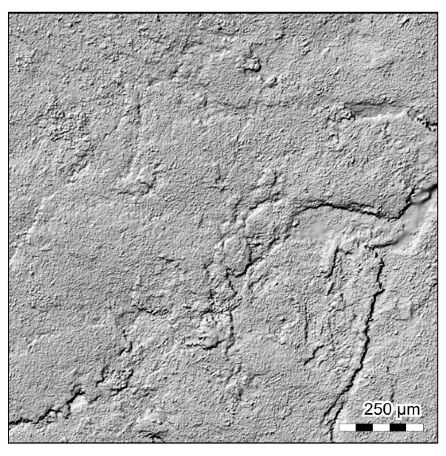
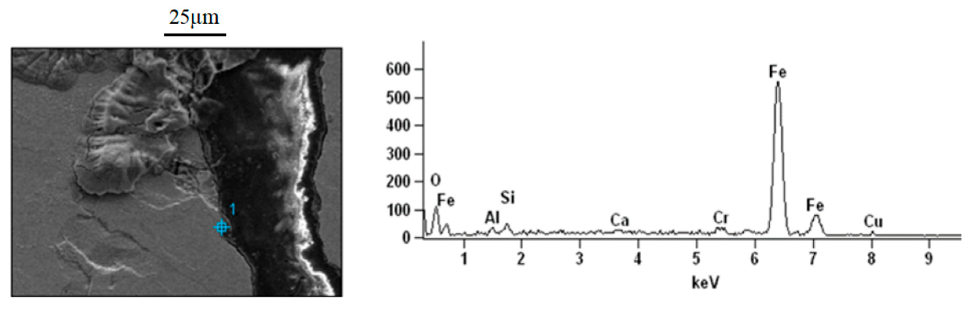
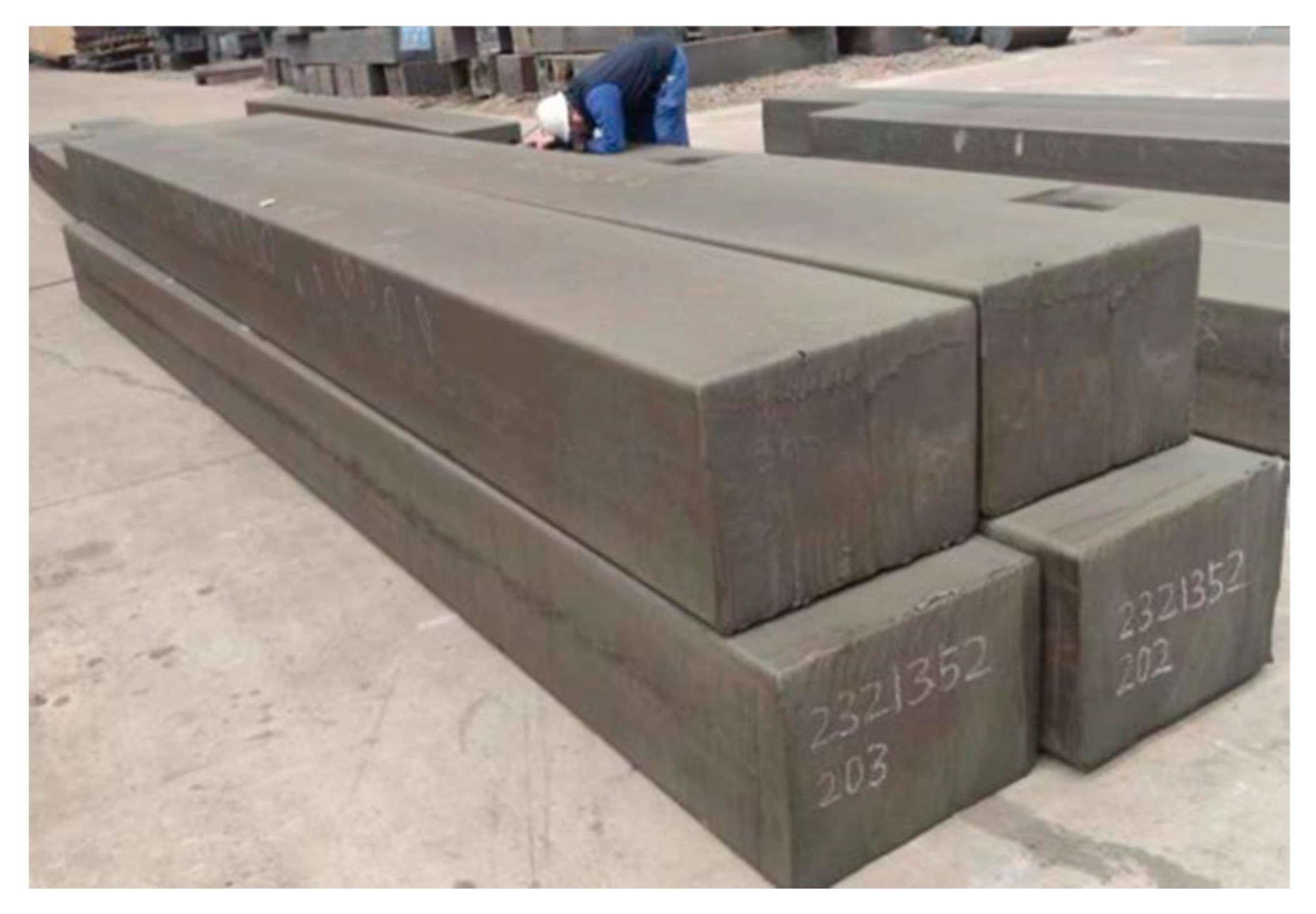
2.2. Defects of Casting Billet
3. Simulation of Solidification Shrinkage Process of Medium-Carbon Special Steel
- (1)
- Since the longitudinal heat transfer of the casting billet is far less than its transverse heat transfer, the longitudinal heat transfer was ignored, and a two-dimensional steady-state model was established to simulate the solidification shrinkage process of the billet in the mold;
- (2)
- The influence of mold oscillation on the heat transfer and solidification of the casting billet was ignored;
- (3)
- Ignoring the longitudinal deformation of the billet, the lateral deformation of the billet was assumed to be a generalized plane;
- (4)
- The convective heat transfer process in the liquid and two-phase regions was replaced with equivalent heat conduction;
- (5)
- An elastoplastic model was used to characterize the mechanical characteristics of the billet at a high temperature;
- (6)
- The initial temperature of the liquid steel remained the same in the calculation area;
- (7)
- The material obeyed the Von Mises yield criterion;
- (8)
- Because the cross section of the casting blank is axisymmetric, a quarter of its cross section was used as the analysis model to simplify the calculation work.
3.1. The Establishment of Mathematical Model
- (1)
- Initial conditions
- (2)
- Boundary conditions
- (3)
- Basic equations of the model
- (4)
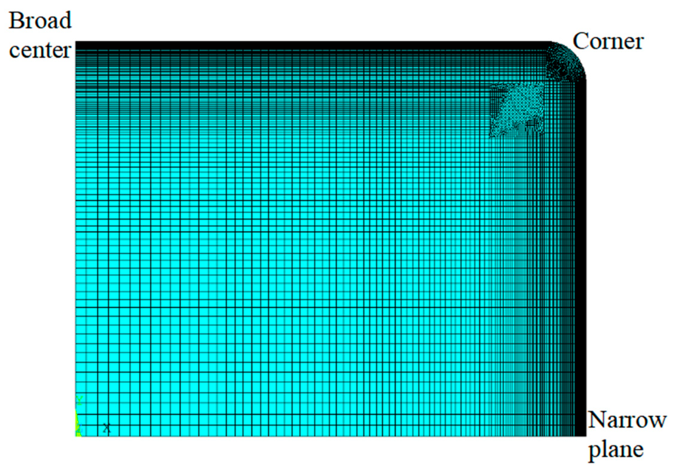
- Finite element model
- (5)
- Verification of model accuracy
3.2. Analysis of Results
- (1)
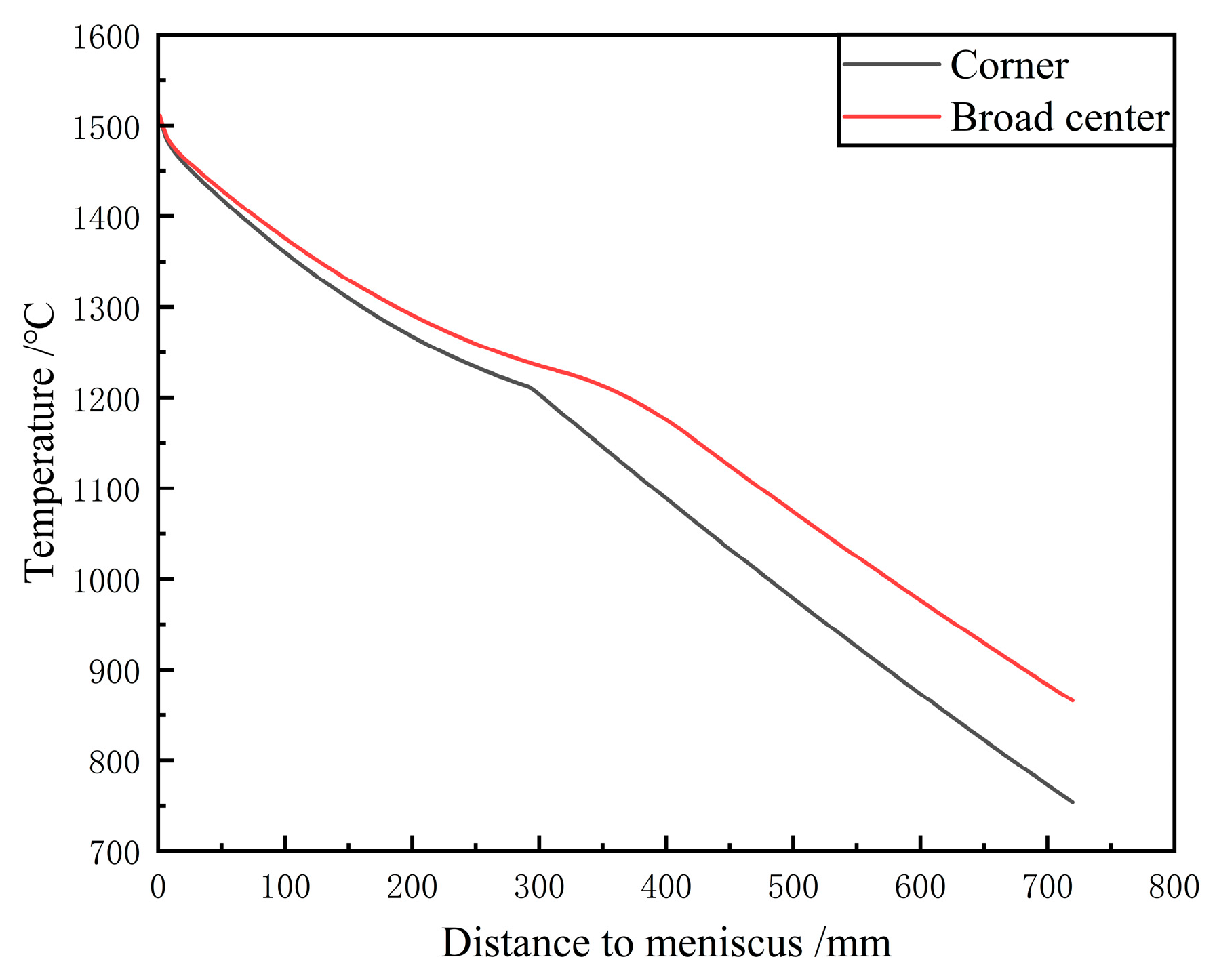
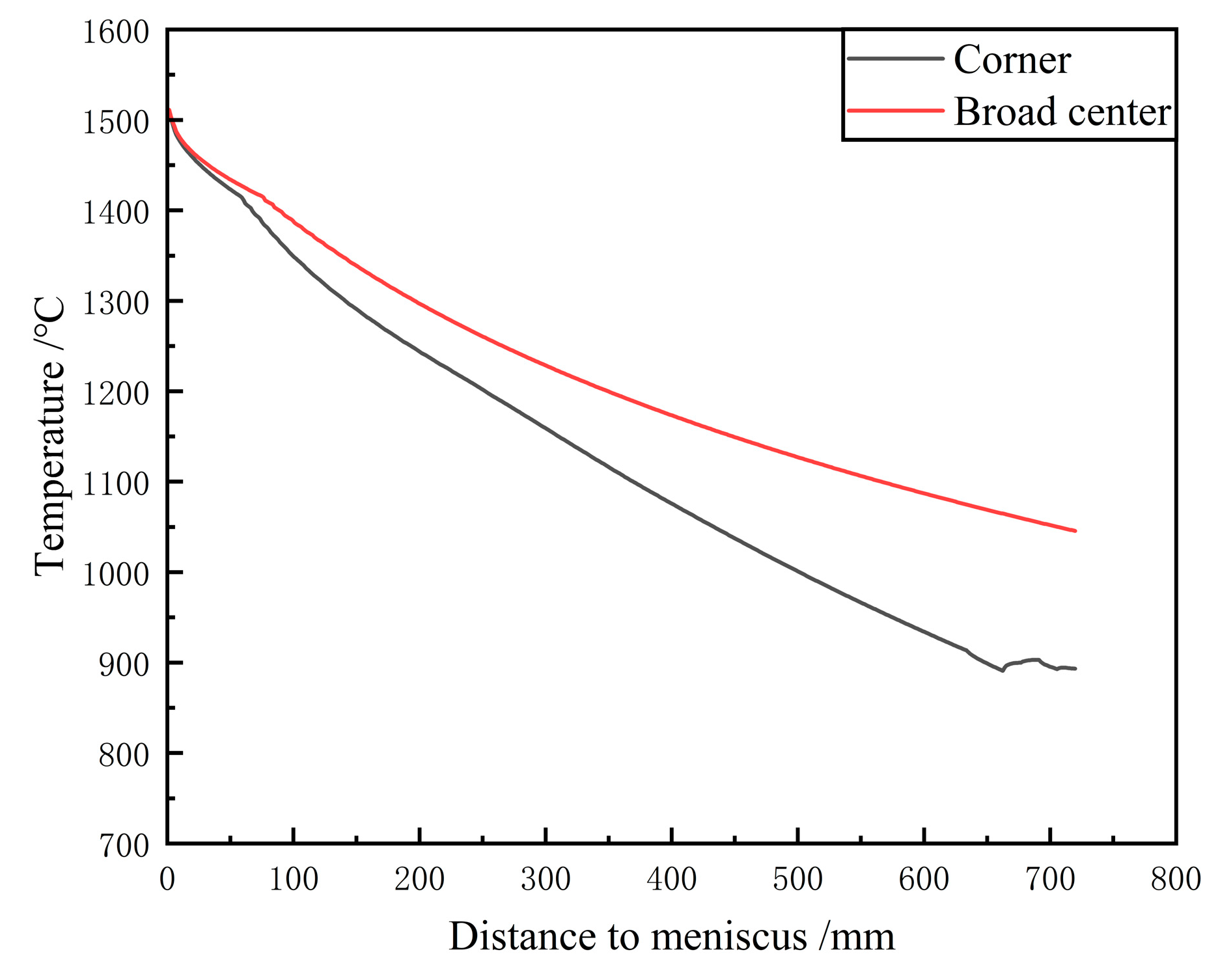
- Analysis of temperature field of casting billet
- (2)
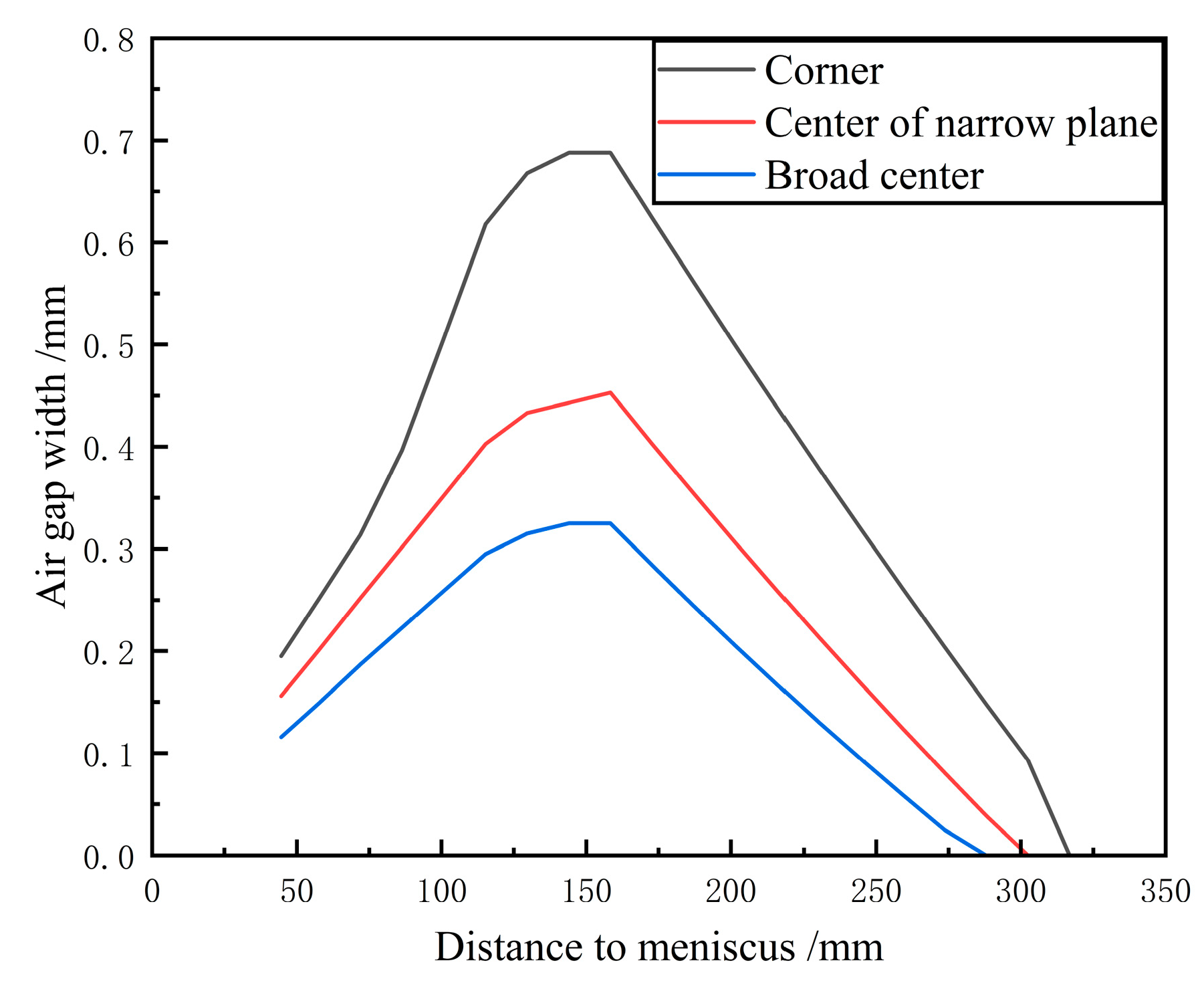
- Air gap analysis between casting billet and mold
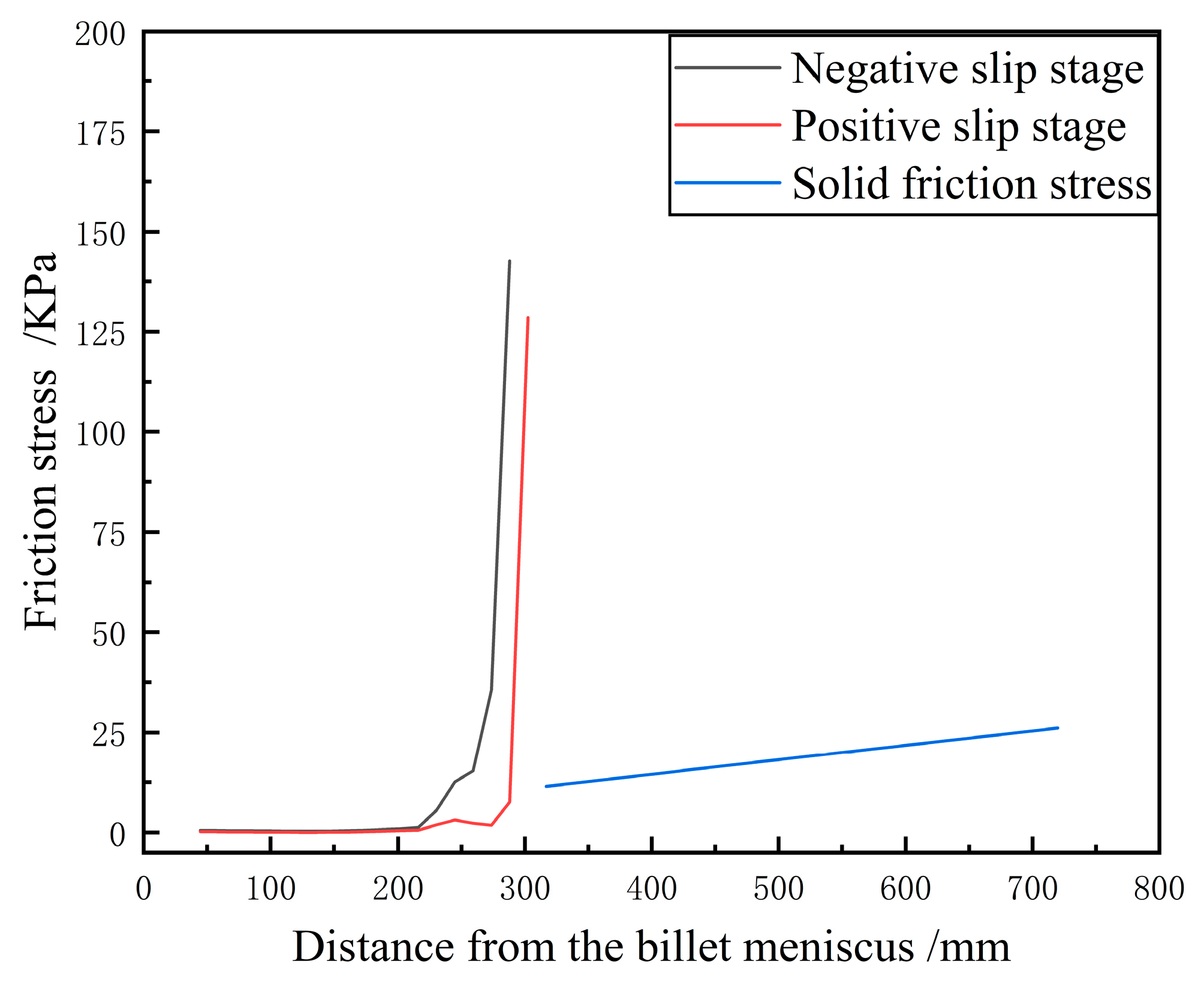
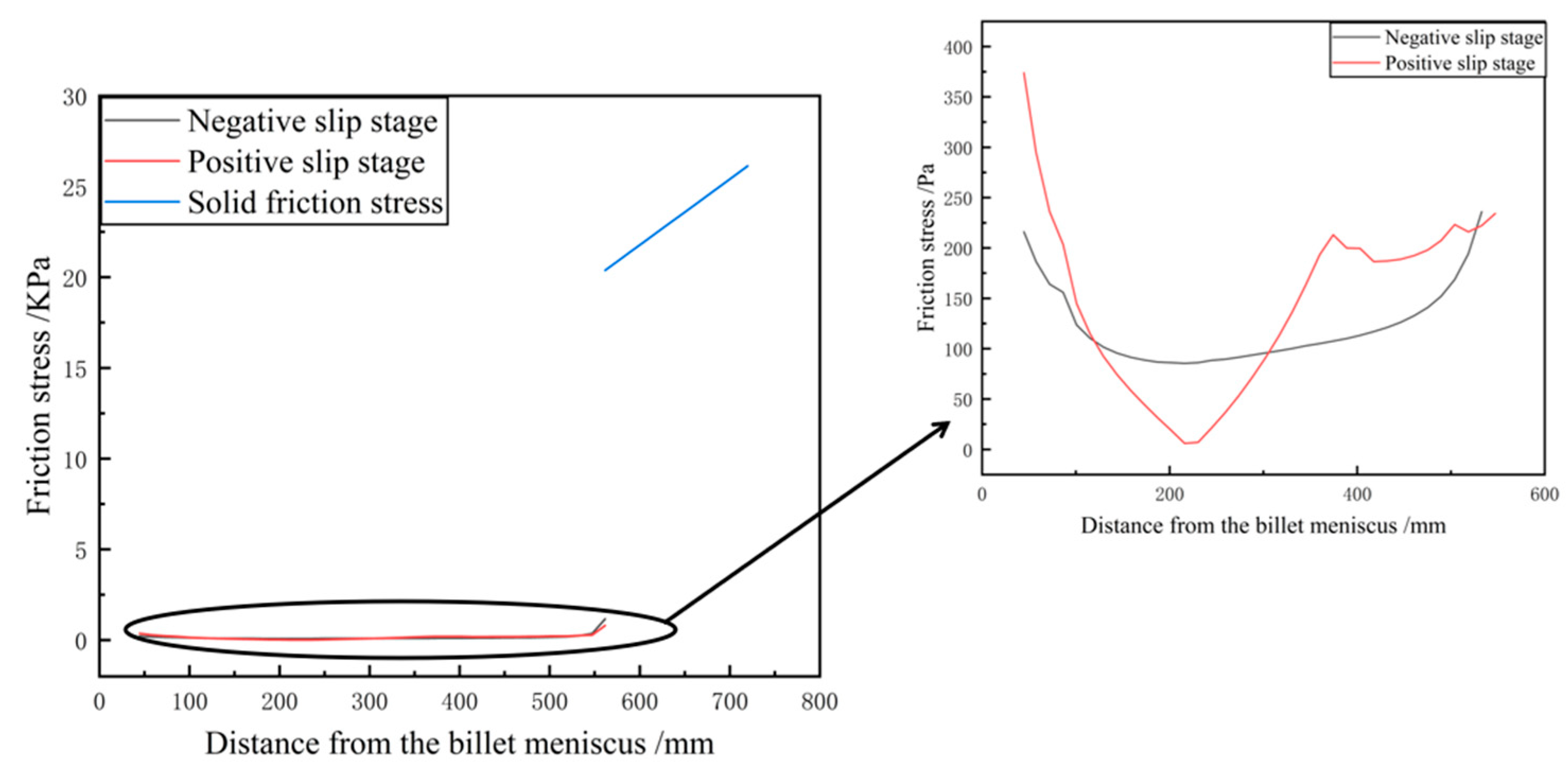
4. Calculation of Friction Stress in Mold
5. Research on the Control of Friction Stress in Molds
5.1. Influence of Taper on Friction in Molds
- (1)
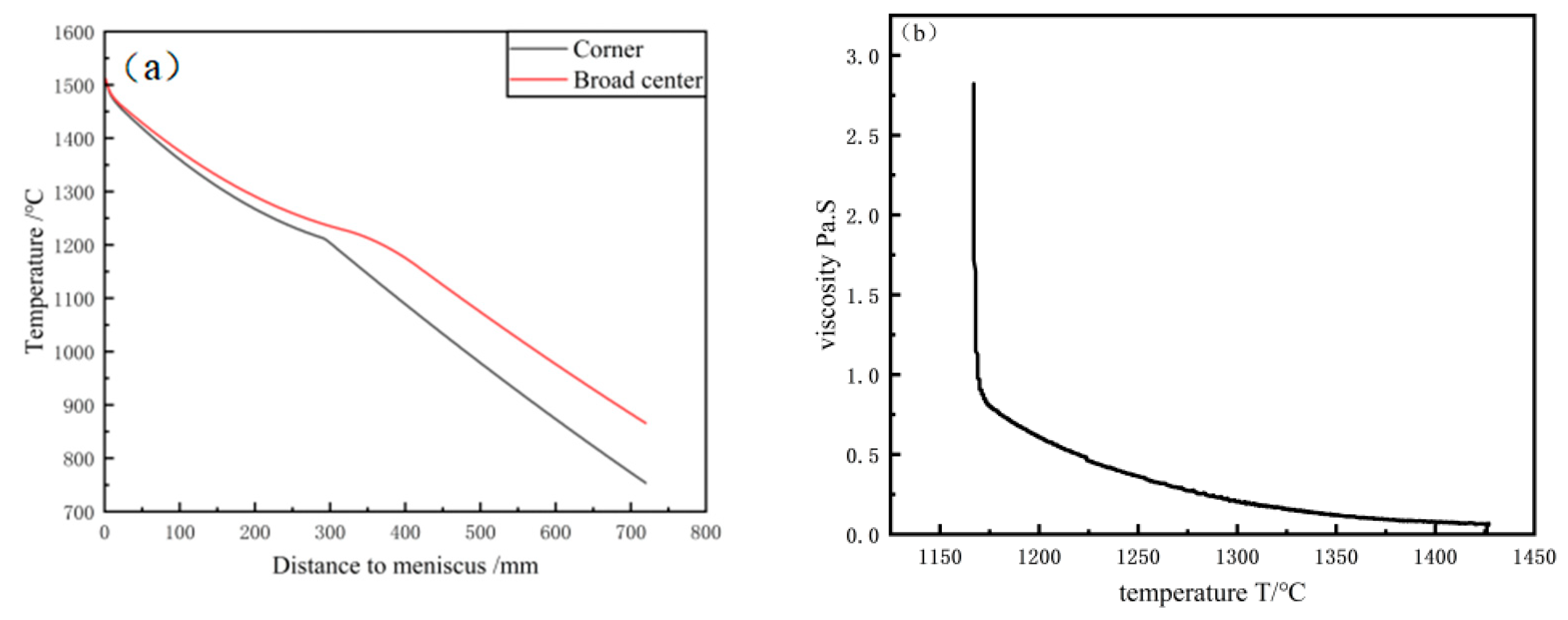
- Analysis of temperature field of casting billet after taper optimization
- (2)
- Air gap analysis between casting billet and mold after taper optimization
5.2. Effect of Physical and Chemical Properties of Casting Powder on Internal Friction Stress of Molds
5.3. Friction Stress Analysis Between Mold and Billet After Optimization
5.4. Relationship Between the Composition of Casting Powder and Friction
5.5. The Application of This Method in Other Cases
6. Conclusions
Author Contributions
Funding
Data Availability Statement
Acknowledgments
Conflicts of Interest
References
- Mondragón, J.J.R.; Trejo, M.H.; de Jesús Castro Román, M.; Solís, T.H. Description of the hypo-peritectic steel solidification under continuous cooling and crack susceptibility. ISIJ Int. 2008, 48, 454–460. [Google Scholar] [CrossRef]
- Wang, X.J.; Tian, K.; Zhu, L.G.; Wang, H.N.; Fan, Y.P. Application of Continuous Casting Mold Fluxes in Crack Sensitive Steel. Iron Steel Vanadium Titan. 2018, 39, 121–126. (In Chinese) [Google Scholar] [CrossRef]
- Gan, Y.; Chen, D.L.; Yang, W.G. The experimental Study on the mould dynamic Friction force in Continuous Casting of steel. Iron Steel 1999, 4, 16–19. [Google Scholar]
- Cai, E.; Xie, B.; Wang, Y. Influence of mold flux properties on the friction between strand and mold. Contin. Cast. 2007, 35–38. [Google Scholar] [CrossRef]
- Meng, X.N.; Zhu, M.Y. Analysis of liquid friction mechanism for slab continuous casting mold with high casting speed. Acta Metall. Sin. 2008, 10, 1193–1197. [Google Scholar] [CrossRef]
- Mizukami, H.; Kawakami, K.; Kitagawa, T.; Suzuki, M.; Uchida, S.; Komatsu, Y. Lubrication phenomena in a mold and optimum mold oscillation mode in high-speed casting. Tetsu Hagane 1986, 72, 1862–1869. [Google Scholar] [CrossRef]
- Valentin, P.; Bruch, C.; Horn, A.C. Friction forces between mould and strand shell during billet casting. Steel Res. Int. 2004, 75, 666–671. [Google Scholar] [CrossRef]
- Däcker, C.A.; Sohlgren, T. The Influence of Mould Powder Properties on Shell Formation in Continuous Casting of Steels. Steel Res. Int. 2010, 81, 899–907. [Google Scholar] [CrossRef]
- Wang, X.D.; Yao, M.; Zhang, L.; Zhang, X.B.; Chen, S.H. Optimization of Oscillation Model for Slab Continuous Casting Mould Based on Mould Friction Measurements in Plant Trial. J. Iron Steel Res. Int. 2013, 20, 13–20. [Google Scholar] [CrossRef]
- Odagaki, T.; Aramaki, N.; Miki, Y.J. Estimation of Lubrication and Heat Transfer by Measurement of Friction Force in Mold. ISIJ Int. 2018, 58, 521–526. [Google Scholar] [CrossRef]
- Niu, Z.Y.; Cai, Z.Z.; Zhu, M.Y. Formation Mechanism of a Wide-Face Longitudinal Off-Corner Depression During Thick Slab Continuous Casting. Metall. Mater. Trans. B 2025, 52, 2737–2752. [Google Scholar] [CrossRef]
- Wang, W.L.; Zhang, H.; Zhang, T.G.; Cai, Z.Z.; Yue, Y.Y.; Zhu, M.Y. Investigation of Multi-interface Heat Transfer Behavior Between Solidified Shell and Copper Mold Tube in Continuous Casting of Bloom. Metall. Mater. Trans. B 2025, 56, 2097–2119. [Google Scholar] [CrossRef]
- Ben, D.Y.; Cai, Z.Z.; Zhu, M.Y.; Xu, D.; Zhao, H.M. Heat transfer behavior of slab solidification in convex lens-shaped mold. China Metall. 2024, 34, 32–43+116. [Google Scholar] [CrossRef]
- Li, Y.; Sun, Y.H.; Song, S.C.; Wang, C. Effect of submerged entry nozzle on molten steel flow in thin slab mold. J. Iron Steel Res. 2024, 36, 66–75. [Google Scholar] [CrossRef]
- Hu, P.H.; Wang, X.D.; Wei, J.J.; Yao, M.; Guo, Q.T. Investigation of Liquid/Solid Slag and Air Gap Behavior inside the Mold during Continuous Slab Casting. ISIJ Int. 2018, 58, 892–898. [Google Scholar] [CrossRef]
- Liu, S.H.; Han, Y.H.; Zhu, L.G. Mathematical model of magnetic field distribution of molten steel in soft-contact electromagnetic continuous casting mold of billet. J. Iron Steel Res. 2021, 33, 1260–1269. [Google Scholar] [CrossRef]
- Wang, Z.P.; Wang, E.G.; Fautrelle, Y.; Zhai, Z.X. Numerical Simulation of Melt Flow, Heat Transfer and Solidification in Final Solidification Zone of Bloom Continuous Casting with Vertical Linear Electromagnetic Stirring. Metall. Mater. Trans. B 2024, 55, 1482–1496. [Google Scholar] [CrossRef]
- Chen, X.Q.; Lei, L.L.; Song, Y.; Xiao, H.; Wang, P.; Feng, W.W.; Zhang, J.Q. Physical and numerical simulation of flow control for submerged entry nozzle in slab continuous casting. China Metall. 2023, 33, 42–55. [Google Scholar] [CrossRef]
- Trejo, M.H.; Lopez, E.A.; Ruiz Mondragon, J.J.; Castro Roman, M.D.; Tovar, H.S. Effect of solidification path and contraction on the cracking susceptibility of carbon peritectic steels. Met. Mater. Int. 2010, 16, 731–737. [Google Scholar] [CrossRef]
- Yin, H.B.; Yao, M.; Zhan, H.Y.; Fang, D.C. 3D stress model with friction in and of mould for round billet continuous casting. ISIJ Int. 2006, 46, 546–552. [Google Scholar] [CrossRef]
- Seppo, L.; Erkki, L.; Risto, N. Real-time simulation of heat transfer in continuous casting. Metall. Mater. Trans. B 1993, 24, 685–693. [Google Scholar] [CrossRef]
- Wang, X.D.; Wang, Z.F.; Yao, M. Online Measurement for Transient Mold Friction Based on the Hydraulic Oscillators of Continuous-Casting Mold. Metall. Mater. Trans. B 2013, 44, 1499–1508. [Google Scholar] [CrossRef]
- Tong, W.J.; Luo, S.; Wang, W.L.; Zhu, M.Y. Modelling of Meniscus Behavior and Slag Consumption During Initial Casting Stage of Continuous Casting Process. Met. Mater. Int. 2024, 30, 2183–2204. [Google Scholar] [CrossRef]
- Meng, Y.; Thomas, B.G. Modeling transient slag-layer phenomena in the shell/mold gap in continuous casting of steel. Metall. Mater. Trans. B 2003, 34, 707–725. [Google Scholar] [CrossRef]
- Yu, S.; Long, M.J.; Liu, P.; Chen, D.F.; Duan, H.M.; Yang, J. Experimental simulation on the high-temperature friction property of slag in slab continuous casting mold. J. Mater. Res. Technol. 2020, 9, 6453–6463. [Google Scholar] [CrossRef]
- Wang, Z.C.; Zeng, J.; Dou, K.; Wang, W.L.; Lin, H.L.; Liu, X.K. Analysis of comprehensive physical and chemical properties of medium and high carbon steel mold flux in thin slab. Contin. Cast. 2023, 27–32. [Google Scholar] [CrossRef]
- Shi, W.N.; Ye, M.Z.; Xu, J.Y.; Wang, J.; Wang, L.; Yuan, Y. Formation mechanism and practical control of surface crack for 09CrCuSb steel billet. Contin. Cast. 2023, 41–47. [Google Scholar] [CrossRef]
- He, H.; Wang, Z.C.; Zeng, J.; Wang, F.K.; Wang, W.L. Research status of the formation and control of surface longitudinal cracks during continuous casting. Contin. Cast. 2024, 1–7. [Google Scholar] [CrossRef]
- Ma, X.G.; Liu, S.G.; Qu, S.; Wang, X.J.; Guo, Y.X. Effect of MgO on Transition Temperature of Continuous Casting Powder for 1Cr13 Stainless Steel. J. North China Univ. Sci. Technol. (Nat. Sci. Ed.) 2022, 44, 24–33. [Google Scholar] [CrossRef]
- Zhu, L.G.; Liu, Y.; Wang, X.J.; Yuan, Z.P.; Piao, Z.L. Effect of carbon blending mode on sintering characteristics of ultra-low carbon continuous casting mold flux. China Metall. 2024, 34, 113–121. [Google Scholar] [CrossRef]
- Li, G.; Pan, W.J.; Li, M.; Zhu, L.L.; He, S.P. Effect of Al2O3 on the physical and chemical properties of ultrahigh-basicity continuous casting mold flux. Chin. J. Eng. 2023, 45, 234–242. [Google Scholar] [CrossRef]


| Ingredient | C | Si | Mn | P | S | Cr | V | Al | Cu |
|---|---|---|---|---|---|---|---|---|---|
| content/% | 0.3~0.4 | 0.5~0.6 | 1~2 | 0.014 | 0.05 | 0.17 | 0.127 | 0.012 | 0.071 |
| Element | O | Al | Si | Ca | Cr | Fe | Cu |
|---|---|---|---|---|---|---|---|
| Weight | 6.24 | 0.14 | 0.28 | 0.18 | 1.01 | 39.24 | 1.23 |
| Atom | 7.15 | 0.10 | 0.18 | 0.08 | 0.36 | 12.88 | 0.35 |
| Compound | 6.24 | 0.14 | 0.28 | 0.18 | 1.01 | 39.24 | 1.23 |
| Item | Value | Unit |
|---|---|---|
| Casting section | 530 × 410 | mm |
| Casting temperature | 1520 | °C |
| Cooling water inlet temperature | 30 | °C |
| Cooling water outlet temperature | 35 | °C |
| Cooling water velocity | 8 | m/s |
| Water tank depth | 7 | mm |
| Mould effective length | 720 | mm |
| Copper wall thickness | 21 | mm |
| Cooling water volume | 210 | W/(m3·h−1) |
| Taper | 1.45 | %·m−1 |
| Solidus Temperatures | 1417 | °C |
| Liquidus Temperatures | 1492 | °C |
| The Casting Billet Exits the Mold | Center Temperature of the Wide Face/°C |
|---|---|
| Measured temperature | 1050 |
| Simulated temperature | 1045.57 |
| Deviation | 0.42% |
| Item | Unit | Parameter |
|---|---|---|
| Mold copper tube length | mm | 800 |
| Cast section | mm | 410 × 530 |
| Mold amplitude | mm | 2 |
| Mold oscillation frequency | frequency/min | 110 |
| Mold taper Angle | %·m−1 | 1.6 |
| Pouring temperature | °C | 1520 |
| Item | Unit | Parameter |
|---|---|---|
| Casting speed | m/min | 0.45 |
| Melting temperature of casting powder | °C | 1211 |
| Transition temperature of casting powder | °C | 1150 |
| Viscosity of mold slag | Pa·s | 0.204 |
| Temperature of hot surface of mold copper plate | °C | 300 |
| Friction coefficient between mold copper wall and solid slag film | 0.5 |
| Ingredient | SiO2 | MgO | CaO | Fe2O3 | Al2O3 | R2O | F− | C |
|---|---|---|---|---|---|---|---|---|
| Content | 29.3 ± 5.0 | ≤5.0 | 36.5 ± 5.0 | ≤3.0 | 5.0 ± 3.0 | 2.0 ± 1.5 | 3.8 ± 2.0 | 10.2 ± 4.0 |
| Melting Temperature | Melting Speed | Crystallization Temperature | Incubation Time | Inflow Temperature | Viscosity | Transition Temperature |
|---|---|---|---|---|---|---|
| 1211 °C | 69 s | 1262 °C | 61 s | 1300 °C | 0.204 Pa·s | 1170 °C |
| Viscosity | Transition Temperature | Melting Temperature | Melting Speed | Crystallization Temperature |
|---|---|---|---|---|
| 0.5~0.6 Pa·s | 1100 °C | 1100 °C | 40~50 s | 1150 °C |
| Type of Casting Powder | Main Components (Base Materials) | Correlation Between Components and Properties | Relationship Between Components and Friction |
|---|---|---|---|
| Casting powder for high-aluminum steel | CaO, SiO2, Al2O3 | Control the content of SiO2 to reduce slag–metal reactions; Li2O lowers the melting temperature, and BaO improves the degree of vitrification, allowing the slag film to uniformly cover the strand shell and reduce cracks caused by local overheating. | Viscosity dominates friction; BaO inhibits crystallization, avoiding friction fluctuations caused by changes in the slag film structure. |
| Casting powder for high-manganese steel | CaO, SiO2, MnO | MnO inhibits the reaction between Mn and SiO2; Al2O3 stabilizes the melt network structure to avoid abrupt changes in viscosity. | Li2O and F− reduce viscosity to minimize friction; BaO improves spreadability to reduce localized friction concentration. |
| Casting powder for high-titanium steel | CaO, Al2O3 | B2O3 forms a composite network with TiO2 to reduce the precipitation of perovskite and avoid sudden increases in viscosity; CaF2 and B2O3 synergistically reduce the melting point and viscosity, making the thermal resistance of the slag film uniform. | The combination of CaF2 and B2O3 improves fluidity and reduces friction peaks caused by local stagnation. |
| Casting powder for high-carbon steel | CaO, SiO2 | CaO slows down the melting of the casting powder; Al2O3 inhibits the precipitation of cuspidine, avoiding uneven heat transfer caused by the crystalline slag film. | If the carbon content (C) is less than 5%, insufficient slag consumption increases friction; if C exceeds 10%, the casting powder melts slowly, resulting in a thin liquid slag layer and an increase in the friction coefficient. |
| Steel Grade | Billet Defect | Frictional Stress Before Improvement | Improvement Measure | Frictional Stress After Improvement |
|---|---|---|---|---|
| Q235 | Surface depression | 200 KPa | Optimize the viscosity of the casting powder; adjust the secondary cooling water volume. | 15~450 Pa |
| 304 stainless steel | Corner crack | 120 KPa | Optimize the composition of the casting powder; adjust process parameters. | 25~500 Pa |
| Low-carbon steel | Crack generation in the upper part of the billet shell | 9.63~10.75 MPa | Increase the mold vibration amplitude; optimize the casting powder. | 10~253 Pa |
| IF steel | Surface crack | 395~620 KPa | Adjust mold parameters; optimize the performance of the casting powder. | 50~289 Pa |
Disclaimer/Publisher’s Note: The statements, opinions and data contained in all publications are solely those of the individual author(s) and contributor(s) and not of MDPI and/or the editor(s). MDPI and/or the editor(s) disclaim responsibility for any injury to people or property resulting from any ideas, methods, instructions or products referred to in the content. |
© 2025 by the authors. Licensee MDPI, Basel, Switzerland. This article is an open access article distributed under the terms and conditions of the Creative Commons Attribution (CC BY) license (https://creativecommons.org/licenses/by/4.0/).
Share and Cite
Wang, X.; Si, X.; Zhu, L.; Wei, T.; Zheng, X. Friction Stress Analysis of Slag Film in Mold of Medium-Carbon Special Steel Square Billet. Metals 2025, 15, 702. https://doi.org/10.3390/met15070702
Wang X, Si X, Zhu L, Wei T, Zheng X. Friction Stress Analysis of Slag Film in Mold of Medium-Carbon Special Steel Square Billet. Metals. 2025; 15(7):702. https://doi.org/10.3390/met15070702
Chicago/Turabian StyleWang, Xingjuan, Xulin Si, Liguang Zhu, Tianshuo Wei, and Xuelong Zheng. 2025. "Friction Stress Analysis of Slag Film in Mold of Medium-Carbon Special Steel Square Billet" Metals 15, no. 7: 702. https://doi.org/10.3390/met15070702
APA StyleWang, X., Si, X., Zhu, L., Wei, T., & Zheng, X. (2025). Friction Stress Analysis of Slag Film in Mold of Medium-Carbon Special Steel Square Billet. Metals, 15(7), 702. https://doi.org/10.3390/met15070702