Article

Effects of In Situ Electrical Pulse Treatment on the Microstructure and Mechanical Properties of Al-Zn-Mg-Cu Alloy Resistance Spot Welds

1
College of Materials Science and Engineering, Beijing University of Technology, Beijing 100124, China
2
Capital Aerospace Machinery Corporation Limited, Beijing 100071, China
*
Author to whom correspondence should be addressed.
Metals 2025, 15(7), 703; https://doi.org/10.3390/met15070703
Submission received: 28 May 2025 / Revised: 17 June 2025 / Accepted: 23 June 2025 / Published: 24 June 2025
(This article belongs to the Special Issue Welding and Fatigue of Metallic Materials)

Abstract

This study introduces a novel in situ pulsed current-assisted resistance spot welding method, which differs fundamentally from conventional post-weld heat treatments and is designed to enhance the mechanical performance of 7075-T651 aluminum alloy joints. Immediately after welding, a short-duration pulsed current is applied while the weld remains in a high excess-vacancy state, effectively accelerating precipitation reactions within the weld region. Transmission electron microscopy (TEM) observations reveal that pulsed current treatment promotes the formation of band-like solute clusters, indicating a significant acceleration of the early-stage precipitation process. Interestingly, the formation of quasicrystalline phases—rare in Al-Zn-Mg-Cu alloy systems—is incidentally observed at grain boundaries, exhibiting characteristic fivefold symmetry. Selected area electron diffraction (SAED) patterns further show that these quasicrystals undergo partial dissolution under the influence of the pulsed current, transforming into short-range ordered cluster-like structures. Lap shear tests demonstrate that joints treated with pulsed current exhibit significantly higher peak load and energy absorption compared to untreated specimens. Statistical analysis of weld size confirms that both groups possess comparable weld diameters under identical welding currents, suggesting that the observed mechanical improvements are primarily attributed to microstructural evolution rather than geometric factors.

1. Introduction

Al-Zn-Mg-Cu-based aluminum alloys have attracted extensive application in aerospace, automotive, and rail transit sectors owing to their high specific strength, excellent corrosion resistance, and reliable fatigue performance [1,2,3]. Within this alloy series, 7075 aluminum alloy is particularly valued for its exceptional strength-to-weight ratio and favorable machinability, making it one of the most widely used grades in advanced structural design. Nevertheless, for heat-treatable aluminum alloys such as 7075, significant strength degradation in the welded joint remains a persistent challenge in resistance spot welding, limiting the reliability of welded assemblies. To address this issue, previous studies have mainly focused on improving the mechanical performance of aluminum alloy joints through conventional post-weld heat treatments. Park et al. [4] investigated paint baking treatment on resistance spot welded joints of A5022-O and age-hardenable A6014-T4 alloys. Their results showed that post-weld heat treatment significantly affected the fracture mode and fatigue behavior of the A6014-T4 joints. Zhang et al. [5] systematically studied bake strengthening behavior in 6061 alloy RSW joints, revealing that microsegregation introduced during welding weakened the precipitation response. They demonstrated that a combined post-weld solution treatment followed by baking could recover strength close to that of the base metal. Additionally, Gáspár et al. [6] proposed a process integrating surface pretreatment and artificial aging to mitigate joint softening in RSW joints of 7075 alloy, which effectively improved both strength and hardness. Although such thermal treatments have proven effective, they are often time-consuming, energy-intensive, and offer limited control over microstructural evolution. Despite these efforts, research remains limited on strategies that leverage the metastable nature of aluminum alloys to achieve rapid precipitation-based strengthening.
In recent years, electrical pulse treatment has emerged as an effective approach for tailoring the microstructure of aluminum alloys, particularly in accelerating precipitation-hardening responses. Shang et al. [7] demonstrated that applying an external electric field to Al-Cu alloys can delay vacancy annihilation after quenching, thereby promoting the early formation of solute clusters (GP zones) and significantly enhancing the hardening kinetics. In 6061 aluminum alloy, Wang et al. [8] found that electrical pulse treatment dissolves pre-existing Mg-Si co-clusters and facilitates the rapid precipitation of needle-like phases during re-aging, enabling efficient strength recovery. In the context of high-strength Al-Zn-Mg-Cu alloys, Xiao et al. [9] showed that electrical pulse treatment, when coupled with thermal input, accelerates GP zone formation, reduces dislocation density, and improves both strength and ductility. Dong et al. [10] further reported that low-temperature pulsing in AA7075-T6 alloys leads to anomalous flow stress behavior, indicating that electrical pulses can influence precipitation pathways and defect evolution by altering the local crystallographic structure.
Although external electric fields have shown great promise in promoting precipitation strengthening in aluminum alloys, their application in welding processes remains largely unexplored. During the resistance spot welding of aluminum alloys, the weld experiences extremely rapid cooling, resulting in a highly non-equilibrium solidification process. This process generates a transient state with a high concentration of excess quenched-in vacancies, which provides fast diffusion pathways for subsequent precipitation reactions. Designing an appropriate post-weld pulsed current strategy could therefore offer a more efficient pathway for strengthening aluminum alloy joints beyond traditional thermal treatments.
In this study, an in situ electrical pulse strengthening method is proposed and experimentally validated for the first time. By applying a short-duration electrical pulse immediately after the welding cycle, the precipitation of band-like cluster structures within the weld is rapidly triggered, resulting in a direct enhancement of joint strength.

2. Materials and Methods

2.1. Materials

In this study, 7075-T651 aluminum alloy plates with dimensions of 2 × 25 × 100 mm were used as the base material for resistance spot welding. As a heat-treatable alloy within the Al-Zn-Mg-Cu system, 7075 is highly sensitive to thermal cycles and external energy fields, under which precipitation phases tend to undergo dissolution, re-precipitation, and other phase evolution behaviors. The T651 temper was selected due to its relatively stable initial microstructure, making it suitable for investigating precipitation responses in the weld region under electrical pulse treatment and their effects on joint performance.

2.2. Experimental Parameters

The welding experiments were performed using an SMD-60 medium-frequency direct current resistance spot welding machine (Haojing Electromechanical, Shanghai, China) equipped with 50 mm diameter RWMA Class II chromium C18200 spherical electrodes. This setup allows for stable electrode pressure and precise current control. An improved welding schedule was adopted in this study, as illustrated in Figure 1. After applying the main welding current for 120 ms to form the weld, the electrodes were held under constant pressure for an additional 100 ms, followed by a short electrical pulse of 10 ms duration and 8 kA in amplitude. Based on whether the post-weld electrical pulse was applied, all the specimens were categorized into two groups: those receiving the electrical pulse treatment (Electrical Pulse-Treated, EPT) and those without it (Non-Electrical Pulse-Treated, NEPT). The detailed welding parameters are listed in Table 1.
To investigate microstructural changes under different processing conditions, specimens welded at 28 kA were selected for detailed characterization. Cross-sections were taken from the weld center and examined using optical microscopy (Leica-MD6M, Fremont, CA, USA) and transmission electron microscopy (JEM-2100, Tokyo, Japan). For optical analysis, the specimens were mechanically polished and etched with Keller’s reagent (47.5 mL distilled water, 1.25 mL nitric acid, 0.75 mL hydrochloric acid, and 0.5 mL hydrofluoric acid) to reveal the macrostructure. TEM was used to observe the morphology, crystal structure, and thermal evolution of precipitates in the weld. All the joints were prepared using a standard lap configuration for mechanical testing. The specimen geometry is shown in Figure 2. Lap shear tests were conducted on a WDW-50 universal testing machine (Shanghai, China) at a constant loading rate of 1 mm/min. During testing, both the peak load and displacement were recorded. The energy absorption of the joint was calculated by integrating the area under the load–displacement curve. These two indicators—peak load and energy absorption—were used to evaluate the mechanical performance of the joint. To reduce random variability, three replicate tests were performed for each welding condition, and the reported values represent their average results. The energy absorption was determined as follows:
E = 0 ε 0 P d ε
where E is the energy absorption, ε0 is the maximum displacement, and P is the instantaneous load.

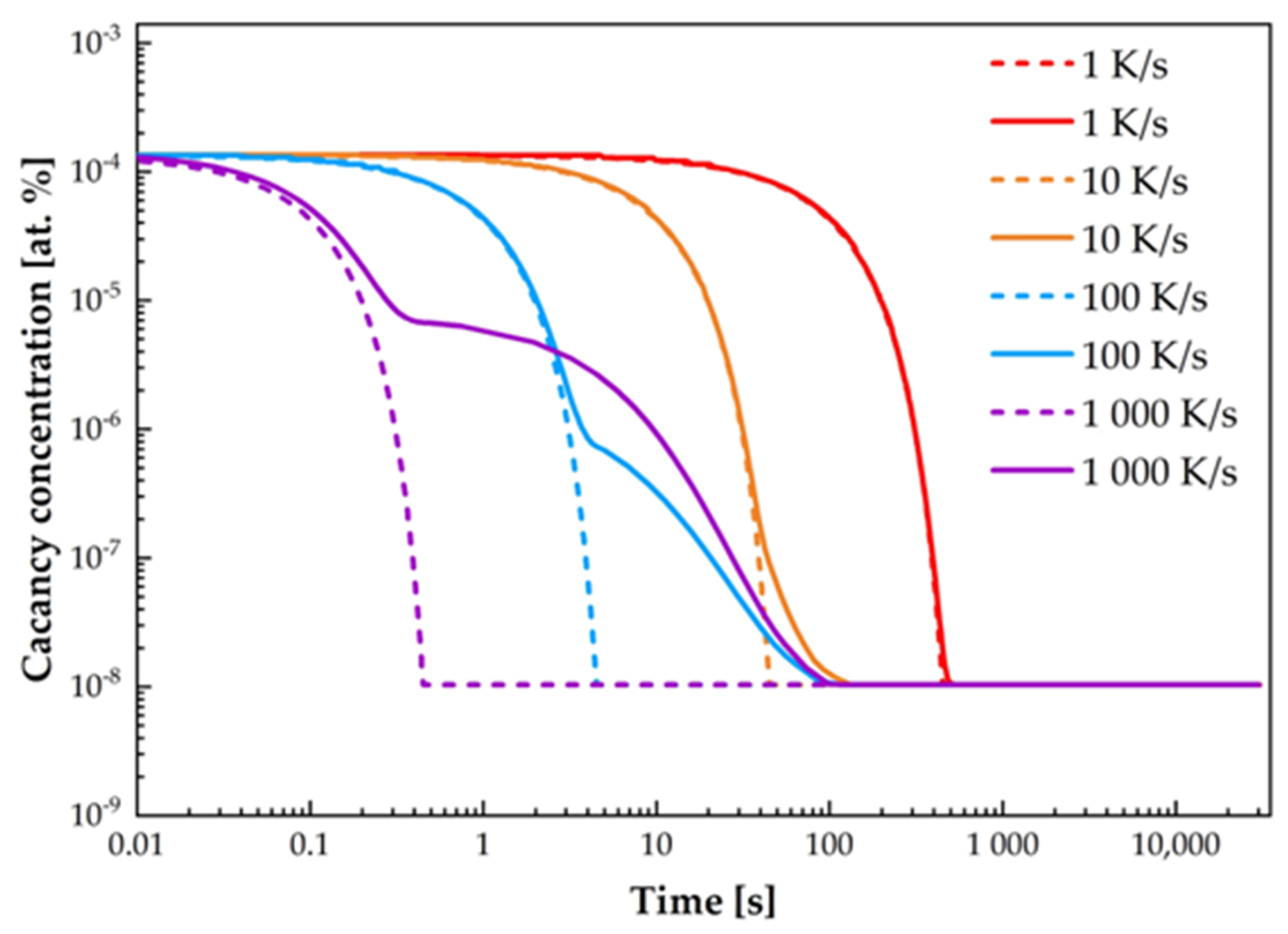
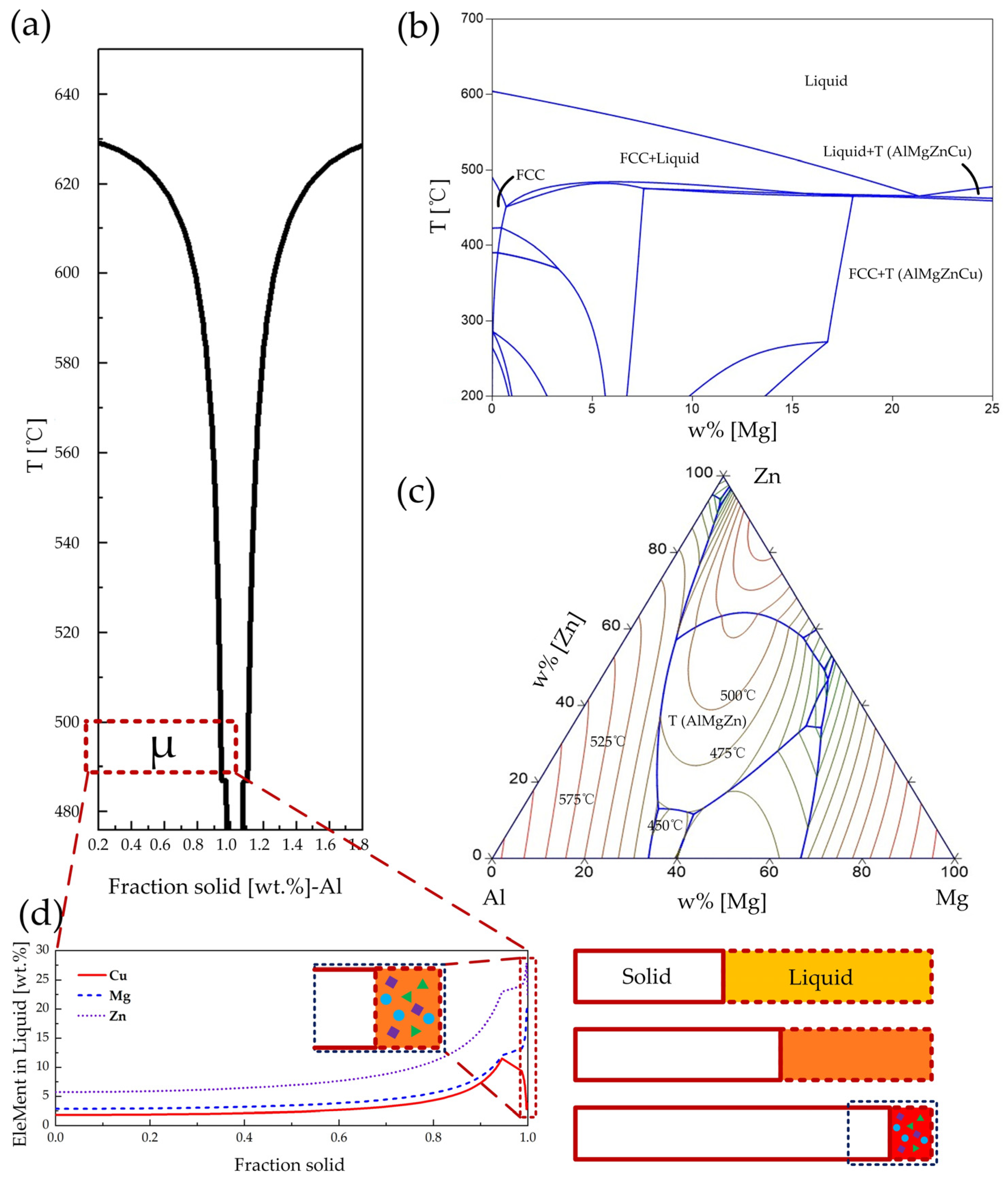
2.3. Vacancy Modeling and Phase Diagram Calculations

To investigate vacancy evolution during the welding thermal cycle and subsequent electrical pulse treatment, numerical simulations were carried out using the MatCalc software package version 6. The chemical composition of the Al-Zn-Mg-Cu alloy was defined as 89.6Al-1.82Cu-2.85Mg-5.73Zn (wt.%). Vacancy kinetics were calculated based on the FSAK (Fischer–Svoboda–Appel–Kozeschnik) model [11], which predicts the time–temperature evolution of free vacancy concentration under specific thermal histories. Detailed simulation parameters are listed in Table 2.
In addition, solidification path calculations were performed using the Scheil–Gulliver model implemented in Pandat. A pseudo-binary phase diagram was constructed to analyze non-equilibrium phase evolution under constrained compositional relationships. This approach offers insight into how variations in elemental ratios influence phase stability and precipitation behavior, providing theoretical support for interpreting microstructural development under pulsed thermal conditions.

3. Results and Discussion

3.1. Microstructural Characteristics

Figure 3 presents the typical microstructural features of 7075 aluminum alloy resistance spot welds produced at a welding current of 28 kA. Figure 3a shows the cross-sectional view of the NEPT specimen, while Figure 3b shows that of the EPT specimen. In both cases, the welds display an elliptical nugget shape with clearly defined heat-affected zone boundaries, which are representative of the solidification characteristics in aluminum alloy resistance spot welding.
The magnified micrographs in Figure 3c–f reveal that the weld microstructure consists of a mixture of columnar and equiaxed grains, with a distinct dendritic growth pattern. In the outer region of the weld, elongated columnar grains grow along the direction of heat flow, whereas the central area contains fine equiaxed grains. This variation in grain morphology results from differences in the temperature gradient and cooling rate during welding. The high thermal conductivity of the copper electrodes creates a steeper temperature gradient near the nugget edge, promoting the directional growth of columnar grains. Toward the center of the weld, the reduced temperature gradient favors simultaneous nucleation in multiple directions, leading to the formation of equiaxed grains. This outward-to-inward grain transition reflects the typical columnar-to-equiaxed transformation commonly observed in aluminum alloy resistance spot welds.
Quantitative analysis of grain size shows that the average columnar grain size is 13.05 μm and the equiaxed grain size is 12.03 μm in the NEPT specimen, while in the EPT specimen, the corresponding values are 13.12 μm and 12.10 μm, respectively. These results indicate that pulsed current treatment does not significantly affect grain coarsening or refinement.
Figure 4 shows a representative bright-field TEM image of the NEPT specimen taken from the weld region. No obvious particulate features, band-like precipitates, contrast discontinuities, or lattice distortions are observed in the field of view. This suggests that under welding conditions without pulsed current, no significant second-phase precipitation has occurred within the weld microstructure.
At the microscopic level, this observation confirms that the high temperatures generated during welding, followed by rapid cooling, result in a supersaturated solid solution. In this state, solute atoms such as Mg, Zn, and Cu are retained in the matrix without sufficient time to diffuse or form clusters and precipitates, leading to the uniformly distributed contrast observed in the TEM image. This metastable condition provides both a strong thermodynamic driving force for subsequent precipitation and a structurally clean matrix for pulse-induced phase evolution.
Figure 5 presents a bright-field TEM image of the weld region in the EPT specimen. In contrast to the NEPT specimen shown in Figure 4, this region exhibits a high density of band-like cluster structures that are finely dispersed throughout the matrix. These features appear as elongated, contrast-rich zones and show a tendency to aggregate within the field of view. The presence of these clusters indicates that the electrical pulse treatment has significantly promoted early-stage solute redistribution and clustering within the weld. In Al-Zn-Mg-Cu alloys, the typical precipitation sequence during aging follows:
S S S S a t o m i c   c l u s t e r s G u i n i e r P r e s t o n   G P   z o n e s η η M g Z n 2
Previous studies have shown that in the early stages of aging in Al-Zn-Mg-Cu alloys, atomic clusters form prior to the appearance of Guinier–Preston (GP) zones and serve as their precursors [19]. The band-like clusters observed in the present study are consistent with this classical precipitation sequence, indicating that the application of electrical pulses effectively accelerates early-stage precipitation processes within the weld.
Resistance spot welding typically subjects the joint to extremely high cooling rates, often exceeding 1000 K/s [20], which results in the generation of a large number of excess vacancies within the nugget. Figure 6 illustrates the time-dependent evolution of vacancy concentration in 7075 aluminum alloy under various cooling rate conditions. The simulation results show that under rapid quenching, the alloy can momentarily reach a high excess vacancy concentration (EVC). However, this elevated EVC state is thermodynamically unstable and rapidly diminishes over time, eventually approaching the equilibrium vacancy level.
In this study, an in situ electrical pulse strengthening strategy was employed to harness the precipitation-promoting effect of excess vacancies before their annihilation. A short-duration pulsed current was applied immediately after the welding cycle, while the electrodes remained in position. This post-weld pulse introduced brief secondary heating to the weld, precisely during the period when the vacancy concentration was still elevated. The thermal and field effects of the pulsed current rapidly activated early-stage precipitation in the alloy, accelerating cluster formation and the initial evolution of metastable phases. These features provided favorable nucleation sites for subsequent strengthening precipitates.
Beyond its thermal effect, pulsed current also exhibits well-documented athermal effects that enhance solute atom mobility within metals [7,9]. These athermal effects become particularly pronounced under non-equilibrium conditions with elevated vacancy concentrations, such as those immediately following welding. During this stage, the interaction between excess vacancies and solute atoms facilitates accelerated diffusion, effectively reducing the time required for precipitation. Moreover, the presence of an electric field can delay the natural decay of excess vacancies, thereby extending the time window during which fast diffusion pathways are available for phase transformation [21,22]. Taken together, these mechanisms allow the pulsed current to accelerate precipitation kinetics under high EVC conditions in the weld, shorten the nucleation and growth timeline, and ultimately improve joint strength.

3.2. Formation and Dissolution of Quasicrystalline Phases

During the TEM observation, a second-phase structure exhibiting distinctive diffraction features was unexpectedly found at the grain boundaries within the weld region. Figure 7 presents bright-field TEM images and corresponding selected area electron diffraction (SAED) patterns from both the NEPT and EPT specimens, taken near the interdendritic grain boundaries. In both cases, clear fivefold symmetric diffraction spots are observed, which are widely regarded as definitive evidence of the presence of icosahedral quasicrystals [23,24]. These results indicate that under the resistance spot welding conditions employed in this study, quasicrystalline phases can form within the interdendritic regions of the weld, regardless of whether pulsed current treatment is applied.
However, further comparison of the SAED patterns reveals a distinct difference in the EPT specimen shown in Figure 7b. In addition to the clear fivefold symmetric diffraction spots, a series of continuous diffraction rings is also observed. This change indicates that the quasicrystalline structure in this region has undergone significant structural evolution under the influence of pulsed current. According to the study by Han et al. [25], the formation of quasicrystals in Al-Cu-Mg-Zn alloys during resistance spot welding originates from deep undercooling and strong solute enrichment in the residual interdendritic liquid. This solute-rich environment facilitates the formation of short-range ordered atomic clusters, which may rearrange cooperatively into a quasicrystalline phase if sufficient atomic mobility is available.
The appearance of diffuse diffraction rings is not associated with a conventional periodic crystal lattice. Instead, it is attributed to the presence of short-range ordered clusters, reflecting a local atomic arrangement with broad orientation distribution and limited long-range order. These findings suggest that the quasicrystalline phases initially stabilized at the grain boundaries underwent partial melting under the combined thermal and electrical effects of the pulsed current, reverting into their precursor state—namely, short-range ordered clusters. Due to the rapid cooling that followed, these clusters were unable to reorder into a quasicrystalline structure and were ultimately “frozen” within the matrix in a disordered state. To gain a preliminary understanding of the spatial distribution of these quasicrystalline phases, it is instructive to estimate their average spacing based on the measured grain size, given their preferential formation along grain boundaries. In the present study, the equiaxed grains near the nugget center exhibit an average size of approximately 12 μm. Assuming that not all grain boundaries host quasicrystals, the average inter-quasicrystal spacing is roughly estimated to fall within the range of 15–30 μm.
Recent studies have demonstrated that quasicrystalline phases, particularly those forming under non-equilibrium solidification conditions, can play a strengthening role by hindering interfacial deformation mechanisms. For instance, in Al-Cu-Fe and Al-Zn-Mg-Cu alloy systems, icosahedral quasicrystals have been shown to exhibit high thermal stability and contribute to localized strengthening by impeding dislocation motion near grain boundaries [26,27]. These quasicrystals, often stabilized by solute enrichment and undercooling, form complex atomic arrangements that disrupt regular slip transmission paths. Furthermore, recent molecular dynamics simulations suggest that disordered intergranular phases, including amorphous films or quasi-periodic structures, introduce excess free volume and strong pinning sites at grain boundaries, thereby increasing the critical stress required for dislocation propagation [28]. Collectively, these findings support the notion that quasicrystalline phases, although metastable, may improve the strength and toughness of welded joints by obstructing dislocation mobility and suppressing grain boundary sliding.
Figure 8 illustrates the proposed formation mechanism of quasicrystals in the weld region of 7075 aluminum alloy resistance spot welds. By combining solidification path analysis, solute enrichment behavior, and phase diagram calculations, a comprehensive explanation can be provided for the preferential formation of quasicrystals at grain boundaries. Figure 8a shows the relationship between temperature and the square root of solid fraction (T- f S ) during weld solidification. According to the solidification theory, f S is positively correlated with the progression of the dendrite front; thus, the shape of this curve reflects the macroscopic solidification profile of dendritic growth within the weld. The red dashed box highlights a representative volume element μ within the dendritic structure, used here to conceptually isolate the local solid/liquid transition during solidification.
To further examine solute behavior within this region, Figure 8d presents the concentration-square root of the solid fraction relationship (C- f S ) for Cu, Mg, and Zn in the representative volume element, derived from the Scheil–Gulliver model. This model assumes negligible diffusion in the solid and complete mixing in the liquid, making it well-suited to simulate solute redistribution under non-equilibrium solidification conditions. When the partition coefficient k is less than 1, solute atoms are continuously rejected into the remaining liquid as solidification proceeds, leading to a rapid increase in solute concentration. In the final stage of solidification (as f S approaches 1), the residual liquid becomes highly enriched and compressed, forming a solute-rich film with low diffusivity. This localized enrichment zone provides a critical chemical environment for the formation of quasicrystalline phases. To assess whether this region meets the thermodynamic requirements for quasicrystal nucleation, Figure 8b,c provide reference phase diagrams. The pseudo-binary Al-Mg diagram in Figure 8b shows that at sufficiently high Mg concentrations, the alloy undergoes eutectic solidification into the T phase (AlMgZnCu) directly from the melt. Meanwhile, the ternary Al-Mg-Zn isothermal section in Figure 8c reveals that the stability region of the T phase expands significantly into Zn- and Cu-rich domains. The existence of such compositionally favorable zones suggests that once the solute concentration in the residual liquid reaches a critical threshold, the driving force becomes sufficient to favor the formation of the T phase or its metastable variant—the quasicrystalline phase.
It is worth noting that previous studies have shown that quasicrystalline phases in Al-Zn-Mg-Cu alloy systems do not typically originate from the transformation of equilibrium solid phases. Instead, they form as metastable products from solute-rich clusters that nucleate within the residual liquid. These clusters serve as fundamental structural units for quasicrystal formation, especially under rapid solidification conditions. During welding, the high cooling rate induced by the electrodes leads to extremely fast solidification of the liquid phase in the weld, severely limiting solute diffusion and inhibiting the atomic rearrangement required for the formation of equilibrium phases such as the T phase. As a result, the solute clusters are unable to fully transition into more stable phases and are instead “frozen” in their quasiperiodic form within the residual interdendritic liquid near the grain boundaries.

3.3. Mechanical Performance of the Joints

Figure 9 presents the microhardness distribution across the cross-section of the resistance spot welds for both the NEPT and EPT samples welded at a current of 30 kA. The nugget, heat-affected zone (HAZ), and base metal (BM) regions are clearly delineated. As shown in the figure, both samples exhibit comparable nugget widths and HAZ boundaries, indicating that the short-duration electrical pulse applied after welding did not significantly alter the overall thermal field or affect the geometric dimensions of the weld.
However, a noticeable difference in hardness is observed within the nugget region. The EPT sample consistently shows higher hardness values compared to the NEPT counterpart, suggesting that the application of pulsed current effectively enhances local strengthening. This improvement is attributed to the pulse-induced acceleration of precipitation reactions during the high vacancy concentration period following welding. While the thermal input from the pulse is insufficient to change the weld size, it evidently promotes microstructural modification within the nugget, thereby improving local mechanical performance.
Figure 10 compares the mechanical performance of the NEPT and EPT specimens across a range of welding currents, focusing on peak load and energy absorption from lap shear tests. Figure 10a shows the peak load results for both specimen types under welding currents from 24 to 32 kA. In general, the peak load increases steadily with higher welding current for both groups, reflecting the typical trend in which increased heat input promotes larger nugget formation and thereby enhances the load-bearing capacity. Notably, the EPT specimens consistently exhibit higher peak loads than their NEPT counterparts across all the current levels, with a maximum improvement of 9.70%. Figure 10b presents the corresponding energy absorption data. Each data point in Figure 10 represents the average value from three independent tests to ensure statistical reliability. It is evident that the EPT specimens also achieve significantly greater energy absorption at every current level tested, with the maximum enhancement reaching 68.98%. These results clearly demonstrate the mechanical strengthening effect of electrical pulse treatment in resistance spot welded joints.
It is worth noting that nugget size is commonly regarded as one of the key factors determining the peak load of resistance spot welded joints. To evaluate whether size effects account for the performance differences, Table 3 summarizes the measured nugget diameters of NEPT and EPT specimens under corresponding welding currents. The results show that the nugget sizes of both groups are nearly identical at each current level, with variations falling within the standard deviation range. This indicates that size is not the dominant factor responsible for the observed differences in peak load.
Therefore, it can be inferred that the application of pulsed current does not significantly alter nugget size. Instead, the observed improvements in peak load and energy absorption are primarily attributed to microstructural differences within the weld. These findings suggest that electrical pulse treatment not only enhances the strength of the joint but also improves its plasticity, resulting in a substantial increase in overall toughness. Taken together, the results confirm that post-weld pulsing effectively accelerates precipitation reactions within the weld, thereby improving the mechanical performance of resistance spot welded joints. From a practical standpoint, given the intrinsic electrical conduction characteristics of resistance spot welding, the proposed pulsed current strengthening strategy is inherently compatible with multi-spot configurations and adaptable to thick-walled components through appropriate tuning of welding parameters.

4. Conclusions

(1)
A resistance spot welding strategy incorporating in situ electrical pulsing under a high excess vacancy concentration (EVC) condition was proposed in this study. This method effectively triggered early-stage precipitation within the weld, promoting the rapid formation of band-like clusters. The observed cluster formation aligns with the classical precipitation sequence of Al-Zn-Mg-Cu alloys, providing a favorable structural basis for the subsequent development of strengthening phases.
(2)
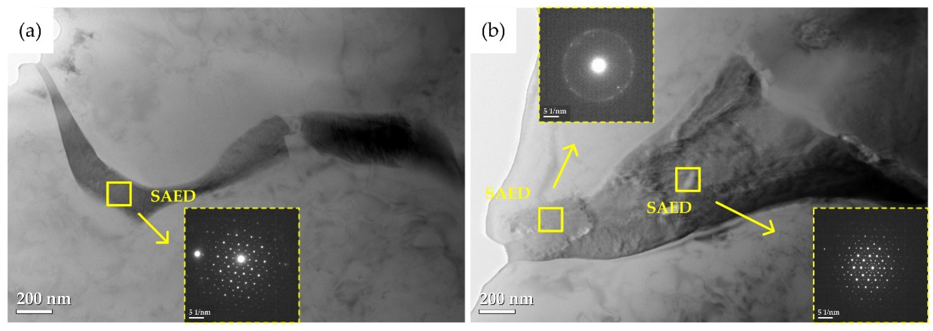
Further TEM analysis revealed fivefold symmetric diffraction patterns in the interdendritic regions of both the NEPT and EPT specimens, confirming the formation of quasicrystals. In the EPT specimens, additional diffuse diffraction rings were observed, indicating the partial dissolution of quasicrystalline phases caused by local heating from the electrical pulses. These structures subsequently transformed into disordered cluster states and were retained in the matrix under rapid cooling conditions.
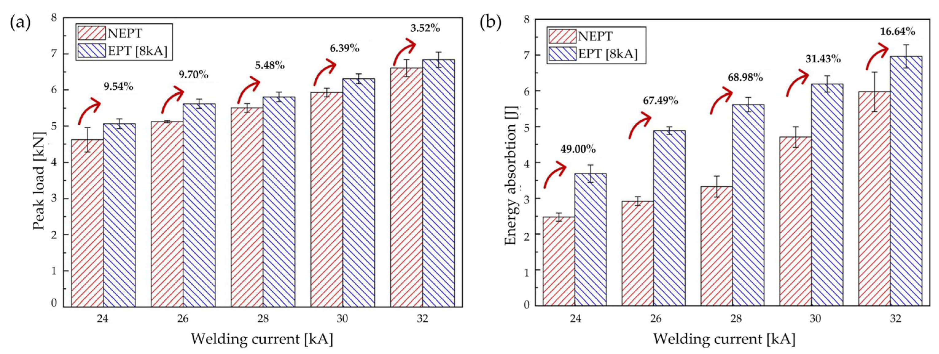
(3)
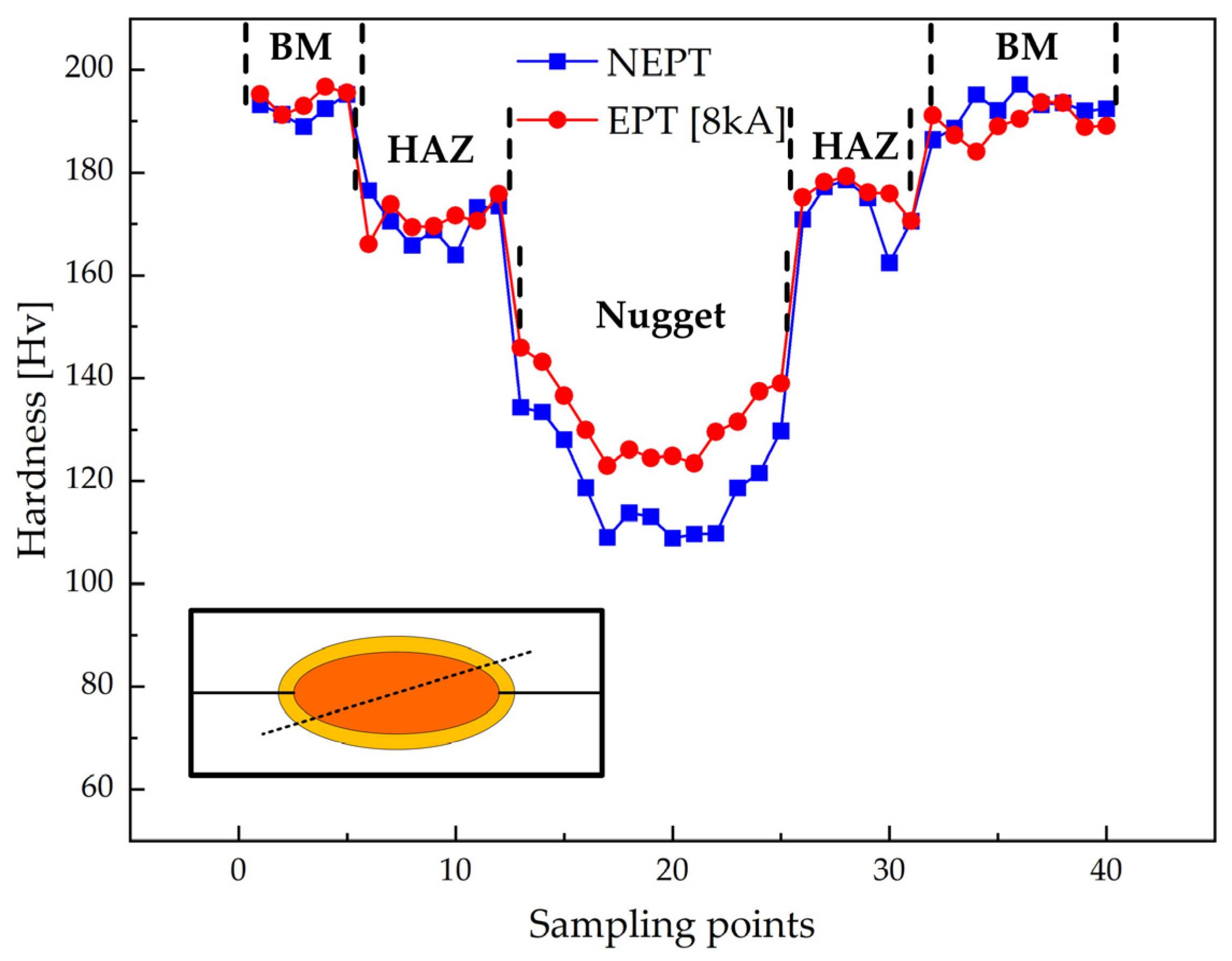
Mechanical testing showed that the EPT specimens exhibited significantly higher peak loads and energy absorption than the NEPT specimens across all the welding currents, with maximum improvements of 9.70% and 68.98%, respectively. Nugget size measurements demonstrated no significant difference between the two groups under the same current, ruling out size effects as the dominant factor. Therefore, the performance enhancement is primarily attributed to microstructural evolution induced by electrical pulse treatment within the weld.

Author Contributions

Conceptualization, S.W. and Y.Z.; methodology, X.M. and Y.Z.; software, X.M. and J.X.; validation, J.X., Y.X. and S.W.; formal analysis, Y.Z.; investigation, X.M.; resources, Y.Z.; data curation, Y.X.; writing—original draft preparation, S.W.; writing—review and editing, Y.Z.; visualization, X.M., J.X. and Y.X.; supervision, Y.Z.; project administration, X.M.; funding acquisition, Y.Z. All authors have read and agreed to the published version of the manuscript.

Funding

This research was supported by the National Natural Science Foundation of China (Grant No. 52275300).

Data Availability Statement

The raw data supporting the conclusions of this article will be made available by the authors upon request.

Acknowledgments

The authors wish to acknowledge the Beijing International Science and Technology Cooperation Base of Carbon-Based Nanomaterials.

Conflicts of Interest

Author Xiaoyu Ma was employed by the Capital Aerospace Machinery Corporation Limited. The remaining authors declare that the research was conducted in the absence of any commercial or financial relationships that could be construed as a potential conflict of interest.

Nomenclature

AbbreviationDescription
RSWResistance Spot Welding
EPTElectrical Pulse-Treated
NEPTNon-Electrical Pulse-Treated
EVCExcess Vacancy Concentration
BMBase Metal
HAZHeat-Affected Zone
TEMTransmission Electron Microscopy
SAEDSelected Area Electron Diffraction

References

  1. Won, S.J.; So, H.; Kang, L.; Oh, S.J.; Kim, K.H. Development of a high-strength Al-Zn-Mg-Cu-based alloy via multi-strengthening mechanisms. Scr. Mater. 2021, 205, 114216. [Google Scholar] [CrossRef]
  2. Wei, S.; Zhang, R.; Liu, X.; Zhang, Y. Comparative Study on the Effect of External Magnetic Field on Aluminum Alloy 6061 and 7075 Resistance Spot-Welding Joints. Metals 2024, 14, 1196. [Google Scholar] [CrossRef]
  3. Guo, X.; Li, H.; Pan, Z.; Zhou, S. Microstructure and mechanical properties of ultra-high strength Al-Zn-Mg-Cu-Sc aluminum alloy fabricated by wire+ arc additive manufacturing. J. Manuf. Process. 2022, 79, 576–586. [Google Scholar] [CrossRef]
  4. Park, H.-G.; Han, S.-C.; Park, C.; Jung, Y.; Jun, T.-S.; Lee, T. Effects of Paint Baking Heat Treatments on Mechanical Properties and Microstructure of Resistance Spot-Welded A5022-O and A6014-T4 Alloys. Metals 2023, 13, 1697. [Google Scholar] [CrossRef]
  5. Zhang, Y.; Li, Y.; Zhu, Z.; Luo, Z.; Manladan, S.M. Bake-strengthening of resistance spot welded aluminum alloy 6061. Weld. J. 2019, 98, 337S–350S. [Google Scholar]
  6. Gáspár, M.; Dobosy, Á.; Tisza, M.; Török, I.; Dong, Y.; Zheng, K. Improving the properties of AA7075 resistance spot-welded joints by chemical oxide removal and post weld heat treating. Weld. World 2020, 64, 2119–2128. [Google Scholar] [CrossRef]
  7. Fu, S.; Zhang, Y.; Liu, H.; Yi, D.; Wang, B.; Jiang, Y.; Chen, Z.; Qi, N. Influence of electric field on the quenched-in vacancy and solute clustering during early stage ageing of Al-Cu alloy. J. Mater. Sci. Technol. 2018, 34, 335–343. [Google Scholar] [CrossRef]
  8. Wang, Y.; Zhang, K.; Wu, W.; Wang, W.; Wang, J. Effect of electrical pulse treatment on the retrogression and re-aging behavior of 6061 aluminum alloy. Mater. Sci. Eng. A 2017, 703, 559–566. [Google Scholar] [CrossRef]
  9. Xiao, A.; Huang, C.; Wang, S.; Yang, J.; Cui, X. Effects of induced electro-pulsing and aging process on properties and microstructure of 7075 aluminum alloy. Mater. Charact. 2022, 192, 112222. [Google Scholar] [CrossRef]
  10. Dong, H.; Li, X.; Li, Y.; Zhao, S.; Wang, H.; Liu, X.; Meng, B.; Du, K. The anomalous negative electric current sensitivity of a precipitation hardened Al alloy during electrically-assisted forming. J. Mater. Res. Technol. 2023, 24, 9356–9368. [Google Scholar] [CrossRef]
  11. Sahoo, J.R.; Bharti, P.; Tripathi, A.; Mishra, S. An experimental and theoretical framework for comprehending the correlation between free vacancy concentration and natural aging susceptibility in Al-Mg-Si alloys. J. Alloys Compd. 2025, 1010, 177939. [Google Scholar] [CrossRef]
  12. Siegel, R.W. Vacancy concentrations in metals. J. Nucl. Mater. 1978, 69, 117–146. [Google Scholar] [CrossRef]
  13. Wolverton, C. Solute-vacancy binding in aluminum. Acta Mater. 2007, 55, 5867–5872. [Google Scholar] [CrossRef]
  14. Fischer, F.; Svoboda, J.; Appel, F.; Kozeschnik, E. Modeling of excess vacancy annihilation at different types of sinks. Acta Mater. 2011, 59, 3463–3472. [Google Scholar] [CrossRef]
  15. Du, Q.; Tang, K.; Marioara, C.D.; Andersen, S.J.; Holmedal, B.; Holmestad, R. Modeling over-ageing in Al-Mg-Si alloys by a multi-phase CALPHAD-coupled Kampmann-Wagner Numerical model. Acta Mater. 2017, 122, 178–186. [Google Scholar] [CrossRef]
  16. Miesenberger, B.; Kozeschnik, E.; Milkereit, B.; Warczok, P.; Povoden-Karadeniz, E. Computational analysis of heterogeneous nucleation and precipitation in AA6005 Al-alloy during continuous cooling DSC experiments. Materialia 2022, 25, 101538. [Google Scholar] [CrossRef]
  17. Li, S.S.; Qiu, F.; Yang, H.Y.; Liu, S.; Liu, T.S.; Chen, L.Y.; Jiang, Q.C. Strengthening of dislocation and precipitation for high strength and toughness casting Al-Zn-Mg-Cu alloy via trace TiB2+ TiC particles. Mater. Sci. Eng. A 2022, 857, 144107. [Google Scholar] [CrossRef]
  18. Du, Y.; Chang, Y.A.; Huang, B.; Gong, W.; Jin, Z.; Xu, H.; Yuan, Z.; Liu, Y.; He, Y.; Xie, F.Y. Diffusion coefficients of some solutes in fcc and liquid Al: Critical evaluation and correlation. Mater. Sci. Eng. A 2003, 363, 140–151. [Google Scholar] [CrossRef]
  19. Geng, Y.; Zhang, D.; Zhang, J.; Zhuang, L. Early-stage clustering and precipitation behavior in the age-hardened Al-Mg-Zn(-Cu) alloys. Mater. Sci. Eng. A 2022, 856, 144015. [Google Scholar] [CrossRef]
  20. Yang, Y.; Bi, Y.; Su, J.; Luo, Z. Precipitate characteristic and nanoindentation analysis of resistance element welded DP780 steel and 6061 aluminum alloy joint. Mater. Lett. 2023, 347, 134571. [Google Scholar] [CrossRef]
  21. Shou, W.; Yi, D.; Yi, R.; Liu, H.; Bao, Z.; Wang, B. Influence of electric field on microstructure and mechanical properties of an Al-Cu-Li alloy during ageing. Mater. Des. 2016, 98, 79–87. [Google Scholar] [CrossRef]
  22. Sun, Q.; Yu, Y.; Wang, F. A novel electromagnetic shock treatment to selectively modify grain boundary and improve the corrosion resistance of aluminium alloy. Mater. Lett. 2023, 334, 133703. [Google Scholar] [CrossRef]
  23. Shechtman, D.; Blech, I.; Gratias, D.; Cahn, J.W. Metallic phase with long-range orientational order and no translational symmetry. Phys. Rev. Lett. 1984, 53, 1951. [Google Scholar] [CrossRef]
  24. AP, T.; Inoue, A.; Yokoyama, Y.; Masumoto, T. Stable icosahedral Al-Pd-Mn and Al-Pd-Re alloys. Mater. Trans. JIM 1990, 31, 98–103. [Google Scholar]
  25. Han, F.; Han, H.; Zhang, Y.; Yuan, T.; Wang, C. Formation mechanism of the quasicrystal in Al-Cu-Mg-Zn aluminum alloy resistance spot weld. Mater. Lett. 2023, 350, 134949. [Google Scholar] [CrossRef]
  26. Grushko, B.; Velikanova, T.Y. Stable and metastable quasicrystals in Al-based alloy systems with transition metals. J. Alloys Compd. 2004, 367, 58–63. [Google Scholar] [CrossRef]
  27. Singh, A.; Hiroto, T.; Ode, M.; Takakura, H.; Tesař, K.; Somekawa, H.; Hara, T. Precipitation of stable icosahedral quasicrystal phase in a Mg-Zn-Al alloy. Acta Mater. 2022, 225, 117563. [Google Scholar] [CrossRef]
  28. Turlo, V.; Rupert, T.J. Grain boundary complexions and the strength of nanocrystalline metals: Dislocation emission and propagation. Acta Mater. 2018, 151, 100–111. [Google Scholar] [CrossRef]
Figure 1. Schematic diagram and process curve of RSW.
Metals 15 00703 g001
Figure 2. Dimensions of the lap shear test specimen.
Metals 15 00703 g002
Figure 3. Cross-sectional metallographs of the Al-Zn-Mg-Cu alloy RSW joints: (a) macroscopic morphology of the nugget in the NEPT specimen; (b) macroscopic morphology of the nugget in the EPT specimen; (cf) enlarged local microstructures corresponding to the regions in (a,b).
Metals 15 00703 g003
Figure 4. Bright-field TEM image of the NEPT specimen.
Metals 15 00703 g004
Figure 5. Bright-field TEM image of the EPT specimen.
Metals 15 00703 g005
Figure 6. Time-dependent evolution of vacancy concentration in the Al-Zn-Mg-Cu alloy under various cooling rates.
Metals 15 00703 g006
Figure 7. Quasicrystal phase and its precursor structure in the weld spot: (a) NEPT specimen; (b) EPT specimen.
Metals 15 00703 g007
Figure 8. Thermodynamic and compositional evolution pathways for quasicrystal formation in the weld spot: (a) T- f S curve during alloy solidification; (b) pseudo-binary phase diagram of the Al-Mg system; (c) isothermal section of the Al-Mg-Zn ternary system; (d) C- f S curves of Cu, Mg, and Zn in volume element μ, along with a schematic illustration of solid/liquid partitioning during solidification.
Metals 15 00703 g008
Figure 9. Cross-sectional microhardness distribution across the weld of the NEPT and EPT specimens.
Metals 15 00703 g009
Figure 10. Lap shear test results of NEPT and EPT specimens: (a) peak load; (b) absorption energy.
Metals 15 00703 g010
Table 1. Welding parameters.
Welding
Current (kA)
Welding
Time (ms)
Electrode
Pressure (kN)
Electrical Pulse
8 kA
241204With/Without
261204With/Without
281204With/Without
301204With/Without
321204With/Without
Table 2. Parameters used as input for executing the FSAK model in MatCalc.
No.NotationVariablesValueReference
1 Δ G f Vacancy formation energy [eV/atom]0.66[12]
2 Δ G b i Binding energy of vacancy and trap: i [eV/atom] Δ G b M g = 0.02 ;
Δ G b C u = 0.02
[13]
3 z Coordination number12[14]
4 f Geometric correlation factor for FCC0.7815[14]
5 V m Molar volume of Al matrix [m3/mol]1 × 10−5[15]
6 γ b Grain boundary energy [eV/m2]3.12 × 1018[16]
7 R Gas constant [eV/atom-K]8.63 × 10−5
8 r Average grain radius [um]13.05
9 ρ Dislocation density [m−2]7.4 × 10¹⁴[17]
10 n p Jog spacing number50[15]
11 Activation energy for diffusion of Mg, Cu [eV]Mg—1.19;
Cu—1.37
[18]
12 Diffusion prefactor [in m/s]1.39 × 10−5[18]
Table 3. Statistical comparison of nugget diameters and standard deviations of EPT and NEPT specimens under different welding currents.
EPT SpecimensNEPT Specimens
Welding
Current (kA)
Nugget
Diameter (mm)
Standard
Deviation
Nugget
Diameter (mm)
Standard
Deviation
247.3507.440.09
267.860.217.850.09
288.280.058.230.06
308.440.108.630.12
329.010.119.020.09
Disclaimer/Publisher’s Note: The statements, opinions and data contained in all publications are solely those of the individual author(s) and contributor(s) and not of MDPI and/or the editor(s). MDPI and/or the editor(s) disclaim responsibility for any injury to people or property resulting from any ideas, methods, instructions or products referred to in the content.

