Abstract
This work investigates the role of friction in the numerical prediction of formability for ultra-thin aluminum sheets made of the EN AW 8006-O alloy. Nakazima-type hemispherical punch stretching tests were conducted under lubricated conditions to assess the influence of interface tribology on thickness distribution and failure behavior. The experimental activity included tensile testing for material parameter identification and coefficient of friction (COF) measurements according to ASTM D1894 to characterize interface friction. These parameters were then implemented into a finite element model developed in PAM-STAMP. The simulation results were compared with experimental thickness profiles, and showed good agreement when calibrated friction coefficients were used. The analysis highlights the sensitivity of sheet deformation to frictional conditions, and demonstrates that accurate tribological input significantly improves predictive accuracy. The proposed workflow offers a reliable and efficient methodology for simulating forming processes involving ultra-thin aluminum foils, with potential applications in the food packaging industry.
1. Introduction
Aluminum alloys are extensively used across several industrial sectors—such as packaging, electronics, and aerospace—due to their low density, corrosion resistance, weldability, and recyclability [1,2,3,4]. Within the packaging industry, EN AW 8006 in the annealed temper (O) is among the most adopted alloys for the production of food trays and containers, thanks to its excellent formability [5,6,7,8,9]. In these applications, sheets with thicknesses as low as 0.1 mm are commonly processed through cold forming techniques, which are both efficient and economically viable [10,11]. However, as sheet thickness decreases, the forming behavior becomes increasingly influenced by factors such as friction, strain localization, and anisotropy, which complicate the prediction and control of formability limits [12,13].
The mechanical characterization of ultra-thin aluminum sheets is typically performed through uniaxial tensile tests [14]. However, these tests fail to reproduce the complex multiaxial stress states that occur in actual forming processes, such as deep drawing or stretching with hemispherical punches. Furthermore, in the case of foils and very thin sheets, tensile tests are highly sensitive to edge defects and specimen preparation methods, which may lead to significant variability in the measured mechanical properties [15,16,17]. As an alternative, forming-based tests (such as free-forming and Nakazima-type hemispherical punch stretching) have been proposed to more accurately replicate the biaxial stress states experienced during industrial sheet metal forming.
Among these, cold free-forming has shown promising results as a cost-effective and experimentally accessible technique. In this context, Parodo et al. [18] investigated the mechanical behavior of the AA8006 aluminum alloy using a room-temperature free-forming process, demonstrating the ability to extract reliable constitutive parameters that are more representative of biaxial loading conditions compared to conventional tensile data. Their study also highlighted the potential of this approach in simplifying the experimental setup while maintaining high accuracy in model calibration.
Friction, which is often oversimplified in numerical simulations, plays a fundamental role in determining the material flow and strain distribution during forming operations. In particular, processes involving hemispherical punch stretching—such as the Nakazima test—are highly sensitive to frictional conditions, which can shift the location of fracture, alter local thinning, and reduce overall formability [19,20]. Despite its significance, friction is frequently modeled using constant Coulomb coefficients, disregarding the actual contact behavior at the blank–tool interface.
Several studies have addressed this issue. Slota and Šiser [21] experimentally demonstrated that variations in frictional conditions significantly affect the fracture location in Nakazima tests on AA5754 aluminum sheets, emphasizing the necessity for accurate tribological characterization. Similarly, Zhang et al. [22] conducted a combined experimental and theoretical analysis on the effect of friction in forming limit curve prediction, showing that simplistic friction models may lead to substantial deviations in the predicted strain paths and forming limits.
In addition to the challenges posed by friction, the characterization of ultra-thin foils requires adapted test configurations. Ayachi et al. [23] proposed a modified Nakazima setup designed to operate at elevated temperatures, which provided valuable insights into the synergistic effects of thermal and tribological factors on material formability. On the numerical side, Bahanan et al. [24] performed finite element simulations of cold deep drawing processes involving aluminum alloys, revealing that both the frictional regime and tool edge geometry substantially affect thickness evolution and strain localization during forming.
Building on these considerations, the present study aims to investigate the role of friction in the formability of ultra-thin EN AW 8006-O aluminum sheets, specifically targeting realistic scenarios in food packaging applications through a combined experimental–numerical approach. Nakazima-type punch stretching tests were carried out under different lubrication conditions, and the resulting data were used to calibrate finite element models that incorporate realistic frictional behaviors. By comparing simulated and experimental dome profiles and thickness distributions, this work highlights the critical influence of tribology in the accurate prediction of material behavior during the cold forming of ultra-thin aluminum sheets.
2. Materials and Methods
The material investigated in this work was a commercially available EN AW 8006 aluminum alloy in the O-temper condition, provided in the form of thin sheets with a nominal thickness of 0.10 mm. The chemical composition of the alloy, consistent with our previous characterization via cold blow forming tests reported in [25], includes Fe (1.2–2.0 wt%), Si (0.4 wt%), Cu (0.3 wt%), Mn (0.3–1.0 wt%), Mg (0.1 wt%), Zn (0.1 wt%), and Al as balances.
2.1. Experimental Activity
The forming apparatus, designed and assembled by the authors, features a rigid hemispherical punch with a radius of 17.5 mm, a die with a circular opening, and a blank holder (Figure 1). Circular blanks with a diameter of 80 mm were clamped using four M10 bolts tightened with a torque of 40 Nm to ensure no relative movement between the sheet and the holder. This configuration is consistent with setups used in literature for ultra-thin forming [23], but all hardware and testing conditions are specific to the present study. Moreover, this clamping configuration ensures rigid fixation of the blank edges, with no relative sliding during deformation, effectively reproducing fixed-edge boundary conditions in both the experiments and simulations.
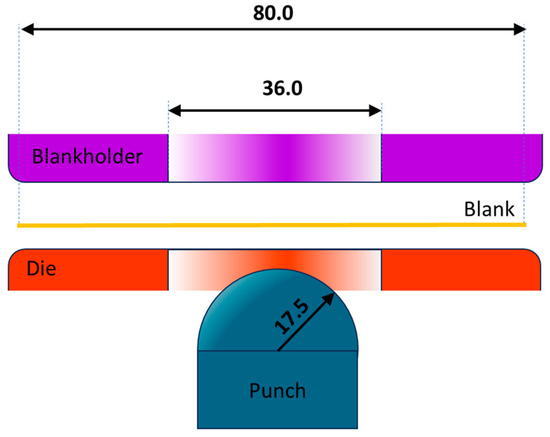
Figure 1.
Sketch of the forming apparatus used in this work (dimensions in mm).
Forming tests were carried out at room temperature by imposing a constant punch speed of 0.25 mm/s until specimen fracture. For lubrication, Softenol 3829 oil was used. The lubricant was applied in controlled amounts, and its main properties are summarized in Table 1.

Table 1.
Physical and chemical properties of Softenol 3829.
The frictional behavior between the sheet and the forming tools was characterized through dedicated tests performed with the IMADA COF Test–MH2 device (IMADA Co., Ltd., Toyohashi, Aichi, Japan), following the ASTM D1894 [26] standard (Figure 2). These tests allowed for the quantification of the static and dynamic coefficients of friction under dry and lubricated conditions.
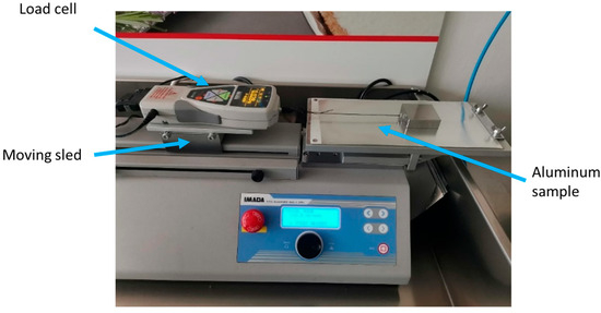
Figure 2.
The COF test in progress using the ASTM D1894 setup. The image shows the contact between the moving sled and aluminum sheet sample under controlled conditions for friction coefficient measurement.
Uniaxial tensile tests were performed in accordance with the European standard EN 546-2 [27], which specifies mechanical requirements and testing procedures for wrought aluminum foil intended for general applications. Rectangular specimens were extracted from the as-received EN AW 8006-O sheets along the rolling direction. The tests were conducted at room temperature using a universal testing machine equipped with a 5 kN load cell and pneumatic grips. The crosshead speed was set to 20 mm/min, while five specimens were tested to ensure statistical significance.
It is worth noting that, due to the specific clamping conditions of the experimental setup, the blank was rigidly fixed between the blank holder and the die, eliminating any relative sliding at this interface. As a result, variations in blank holder force were not meaningful in this study. Instead, the friction conditions at the punch-sheet interface, strongly influenced by the applied lubricant (Softenol 3829), play a dominant role in local thinning and strain localization. Consequently, the coefficient of friction (COF) was chosen as the primary variable investigated both experimentally and numerically.
2.2. Numerical Activity
Numerical simulations were performed using the commercial finite element software PAM-STAMP (2022.0) to investigate the influence of friction on the formability of thin EN AW 8006-O aluminum alloy sheets under hemispherical punch loading. A 2.5D finite element model was adopted to simulate the hemispherical punch stretching test, allowing an efficient balance between computational cost and predictive accuracy, without exploiting geometric symmetry (Figure 3 and Figure 4). The initial mesh consisted of shell elements with an approximate size of 3 mm. However, adaptive remeshing was activated, with the ability to split each element into 4 sub-elements up to 7 times, resulting in a minimum local element size of about 0.023 mm in highly deformed zones. This dynamic refinement allowed the model to accurately capture localized strain and thinning, without requiring a traditional mesh convergence study.
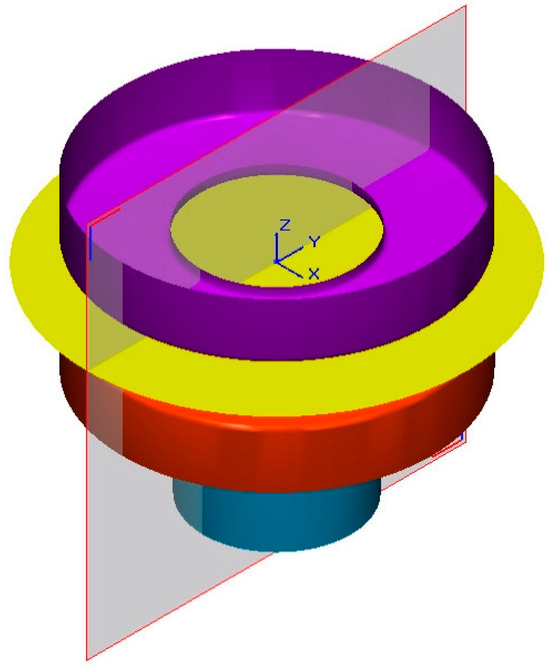
Figure 3.
The CAD model of the tooling used in the Nakazima test, showing the hemispherical punch (blue), die (red), blank holder (purple) and blank (yellow). Moreover, the reference frame and the section plane are also reported.
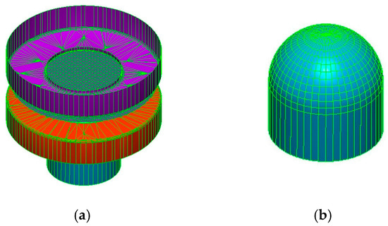
Figure 4.
Mesh used for simulating the Nakazima test: (a) assembly and (b) particular of the hemispherical punch.
The blank was modeled using Belitschko–Tsay shell elements, which are specifically formulated for thin structures and capable of representing both membrane and bending effects. The mesh was refined in the central region of the blank to ensure the accurate prediction of strain localization and thinning. The punch and die were modeled as analytical rigid surfaces. Contact interactions between the sheet and the tools were defined using a standard Coulomb friction law.
The material behavior was described by an elasto-plastic constitutive model with isotropic hardening. The flow curve used in the simulations was obtained from uniaxial tensile tests carried out in accordance with EN 546-2, and converted to true stress–strain form. Specifically, the hardening behavior was implemented using the Hollomon equation:
where k is the strength coefficient and n is the strain hardening exponent.
A parametric sensitivity analysis was conducted to evaluate the effect of friction on the forming process. To this purpose, three different friction coefficients were considered: μ = 0.10, 0.20, and 0.30. These values were not directly derived from experimental measurements but rather selected to explore a representative range of contact conditions.
Contact interactions between the tools and the sheet were modeled using the Coulomb friction law:
where ft il the frictional shear stress, µ is coefficient of friction (COF), and fn is the contact pressure.
A schematic overview of the validation procedure is shown in Figure 5. The numerical model was calibrated using experimental inputs for the mechanical response (from EN 546-2 tensile tests) and for the friction coefficient (from ASTM D1894 measurements), and was validated against experimental Nakazima tests in terms of thickness evolution. Specifically, specimens were deformed using a hemispherical punch until reaching punch displacements of 5 mm and 10 mm, respectively. The tests were interrupted before the onset of necking or fracture, allowing for the evaluation of thickness distribution at controlled levels of deformation. All interruption tests were carried out under lubricated conditions. This ensured consistency in frictional behavior and allowed a direct comparison with the numerically predicted thickness profiles. The experimental data collected at intermediate strokes served as a fundamental benchmark for validating the finite element model and evaluating its capability to accurately reproduce the material response throughout the forming process. Thickness evolution was experimentally measured using a MagnaMike 8600 (Olympus Scientific Solutions Americas, Waltham, MA, USA) Hall-effect gauge, an instrument with micrometric resolution. This preliminary comparison enabled the assessment of the model’s reliability. Once validated, the model was used to perform a parametric sensitivity analysis, in which the friction coefficient was varied beyond the experimental values to explore its influence on forming behavior.
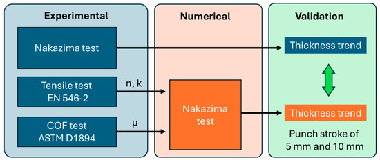
Figure 5.
Experimental–numerical workflow. Tensile and friction tests provide input parameters (n, k, μ) for the numerical Nakazima simulation. Experimental and simulated thickness trends are then compared for validation.
3. Results and Discussion
3.1. Experimental Results
Table 2 and Figure 6 show the results from tensile tests. It is worth noting that the experimental scatter among replicates was relatively low, with a standard deviation below 2% for stress and below 5% for strain, confirming the good repeatability of the tensile tests.
Table 2.
Tensile test results.
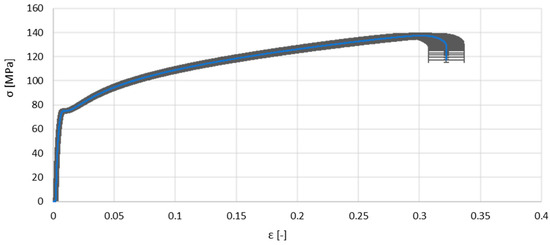
Figure 6.
Mean engineering stress–strain curve with a standard deviation band based on five tensile tests.
Figure 7 reports the experimental results obtained from the ASTM D1894 friction tests for both the dry (degreased) and lubricated (oiled) conditions. Figure 7a shows the force–displacement curves recorded during the sliding tests, while Figure 7b summarizes the average values and standard deviations of the static and dynamic coefficients of friction (COF). As expected, the application of the Softenol lubricant led to a significant reduction in both static and dynamic friction. The static COF decreased from approximately 0.33 in the degreased condition to 0.16 in the lubricated case, while the dynamic COF was reduced from around 0.21 to 0.10. The lower friction levels under lubrication are also reflected in the force–displacement response, where the oiled condition exhibits lower average forces and reduced fluctuations throughout the sliding path.
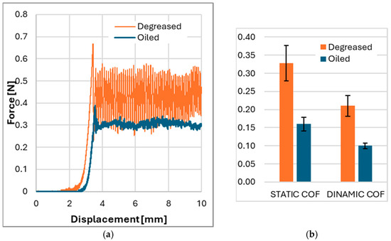
Figure 7.
Results of the ASTM D1894 friction tests under dry and lubricated conditions: (a) force–displacement curves acquired during sliding and (b) the average static and dynamic coefficients of friction with corresponding standard deviations.
The dry condition is characterized by a force signal with larger amplitude oscillations, which are commonly associated with stick-slip behavior, due to intermittent local adhesion and micro-jumps at the contact interface. In contrast, the lubricated curve presents a smoother profile, indicative of stable sliding and better lubrication performance.
These results confirm the effectiveness of Softenol in reducing contact friction under the specific test configuration and justify considering it in the simulation model as a condition with significantly lower interface resistance.
3.2. Numerical Results
Figure 8 shows the comparison between numerical predictions and experimental measurements of thickness distribution along the reference section plane for punch displacements of 5 mm and 10 mm under lubricated conditions (COF = 0.1). The numerical results capture the overall shape of the thickness profiles, including the location and magnitude of thinning, with reasonable agreement across both stroke levels.
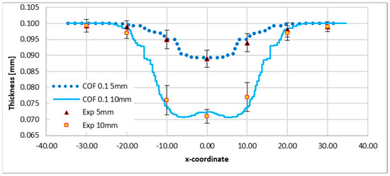
Figure 8.
Numerical and experimental comparison of thickness trends along the reference section plane for COF = 0.1 with punch displacements of 5 mm and 10 mm.
At 5 mm of punch displacement, the predicted thinning is slightly overestimated in the central region (x ≈ 0 mm), while at 10 mm of displacement, the numerical model shows excellent agreement with experimental data, particularly in terms of the minimum thickness and the steepness of the gradient near the transition zones (x-coordinate between 15 and 20 mm). The trend indicates a progressive intensification of thinning as the punch stroke increases, which is physically consistent with the expected material flow behavior during hemispherical stretching. The error bars associated with the experimental points highlight the variability in measurements, especially at higher deformation levels. Nevertheless, the model calibrated with a COF of 0.1 demonstrates good capability in predicting the evolution of local thickness under different forming conditions. These results confirm the suitability of the adopted friction coefficient, and validate the reliability of the numerical approach in capturing intermediate deformation states.
Figure 9 and Figure 10 present the numerical predictions of thickness distribution along the reference section plane for COF = 0.2 and COF = 0.3, respectively, considering punch displacements of 5 mm and 10 mm. The results demonstrate the progressive thinning behavior as both the punch stroke and the friction coefficient increase.
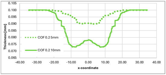
Figure 9.
Numerical thickness trends along the reference section plane for COF = 0.2 with punch displacements equal to 5 mm and 10 mm.
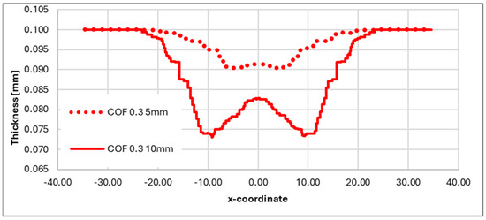
Figure 10.
Numerical thickness trends along the reference section plane for COF = 0.3 with punch displacements equal to 5 mm and 10 mm.
In Figure 9, for COF = 0.2, the profiles show moderate thinning at the dome apex, with a minimum thickness of approximately 0.073 mm for the 10 mm stroke. The transition between the central and peripheral regions remains smooth, indicating reasonably homogeneous material flow.
In Figure 10, with COF = 0.3, the influence of friction becomes more pronounced. The higher interfacial resistance limits radial material flow, resulting in sharper gradients and a deeper thinning zone. At a 10 mm stroke, the minimum thickness falls below 0.070 mm, suggesting a near-critical forming condition. The steepness of the curves near the transition zone are markedly increased compared to the lower COF cases, pointing to a more localized deformation pattern. Overall, the comparison across Figure 9 and Figure 10 confirms that increasing the friction coefficient leads to reduced formability and a higher risk of localized failure. These findings emphasize the importance of accurate tribological characterization for predictive numerical modeling of thin sheet forming operations, especially for thin sheets.
Figure 11 illustrates the simulated thickness distributions for different combinations of punch stroke (5 mm and 10 mm) and friction coefficient (COF = 0.1, 0.2, 0.3). As expected, increasing the punch stroke results in a more pronounced thinning at the dome apex due to greater plastic deformation induced by the deeper penetration of the punch.
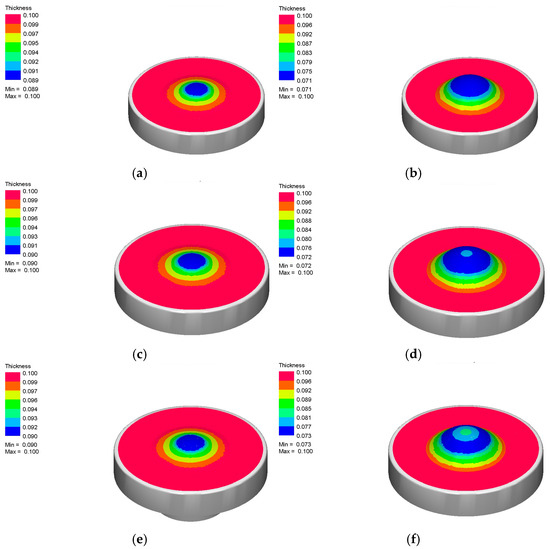
Figure 11.
Thickness distribution (dimensions in mm) for: (a) COF = 0.1 and a punch stroke equal to 5 mm; (b) COF = 0.1 and a punch stroke equal to 10 mm; (c) COF = 0.2 and a punch stroke equal to 5 mm; (d) COF = 0.2 and a punch stroke equal to 10 mm; (e) COF = 0.3 and a punch stroke equal to 5 mm; and (f) COF = 0.3 and a punch stroke equal to 10 mm.
For each stroke level, the effect of friction is clearly visible. At a lower friction (COF = 0.1), material flow is more uniform, leading to a smoother thickness gradient and less severe thinning (Figure 11a,b). As the friction coefficient increases to 0.2 and 0.3, the contact resistance at the blank–tool interface becomes more significant, restricting radial flow and causing a sharper localization of thinning at the pole (Figure 11d–f).
Comparing the same COF across the two strokes (e.g., Figure 11a vs. Figure 11b, Figure 11c vs. Figure 11d), it is evident that the interaction between friction and stroke amplifies the thinning effect, particularly at a high COF. In Figure 11f (COF = 0.3, stroke = 10 mm), the most critical condition is reached, where the minimum sheet thickness drops below 0.07 mm, suggesting a high risk of failure due to excessive local thinning.
The obtained results highlight the importance of accurate tribological characterization when simulating the behavior of EN AW 8006-O aluminum alloy during hemispherical punch forming. The discrepancies observed between simulations using assumed constant friction values and those calibrated with experimental data confirm what has already been reported in the literature: the friction coefficient significantly affects material flow, thickness evolution, and the onset of plastic localization [22]. The adoption of an integrated experimental–numerical approach allowed us to overcome the limitations associated with simplified friction models, which are often used either to reduce computational time or due to a lack of reliable input data. In this work, the use of friction coefficients obtained in accordance with ASTM D1894 led to a significant reduction in error when predicting minimum thickness and dome height, aligning well with the observations of Bahanan et al. [24]. Particularly noteworthy is the system’s sensitivity to friction under dry conditions, where the prediction of radial flow—and consequently the thickness distribution—worsens. This is attributable to the increased sliding resistance, which hinders the material from conforming to the punch profile and favors the early onset of instability.
The increase in friction coefficient was found to significantly affect the thickness distribution, leading to localized thinning. This observation is in agreement with the findings of Slota and Šiser [21], who demonstrated that higher friction levels shift the fracture location in Nakazima tests on AA5754 alloys. Similarly, the steeper gradients observed at COF = 0.3 in our simulations confirm the trends described by Zhang et al. [22] regarding friction-sensitive strain localization
Finally, it is worth emphasizing that, beyond model validation, the adopted methodology provides useful design insights for optimizing process parameters in real-world applications. The ability to predict thinning magnitude and localization paves the way for strategies such as adjusting blank holder force, selecting more effective lubricants, or even tailoring the initial blank geometry according to a design-for-forming philosophy.
It should be noted that the friction model adopted in this study assumes a constant coefficient of friction. While this simplification is acceptable under controlled forming conditions, more advanced friction laws (accounting for pressure, velocity, and lubrication regimes) could further enhance the predictive capability of numerical simulations, especially under variable forming conditions.
4. Conclusions
This study investigated the influence of friction on the formability of ultra-thin EN AW 8006-O aluminum sheets through a combined experimental–numerical approach. Friction coefficients were measured experimentally under dry and lubricated conditions following ASTM D1894, and incorporated into finite element simulations of Nakazima-type hemispherical punch tests using PAM-STAMP. The results demonstrate the following:
- The use of experimentally derived friction coefficients significantly improves the predictive accuracy of numerical simulations, particularly in terms of minimum thickness and dome height.
- Higher friction levels hinder radial material flow, leading to more localized thinning and reduced formability. This effect becomes more pronounced at higher punch strokes.
- The comparison between experimental and numerical thickness profiles validates the reliability of the modeling approach and confirms the critical role of accurate tribological input in forming simulations.
- The adopted methodology provides a robust and efficient tool for evaluating and optimizing forming conditions in industrial applications involving thin aluminum foils, such as food packaging.
Overall, the integrated experimental–numerical workflow presented in this work offers a reliable framework for simulating sheet metal forming operations, supporting the design of more effective and robust forming processes for ultra-thin materials.
Author Contributions
Conceptualization, G.P., L.S. and G.M.; methodology, G.P., L.S., S.T. and G.M.; validation, G.P., L.S., S.T. and G.M.; formal analysis, G.P., L.S., S.T. and G.M.; investigation, G.P. and G.M.; data curation, G.P. and G.M.; writing—original draft preparation, G.P. and G.M.; writing—review and editing, L.S. and S.T.; visualization, G.P., L.S., S.T. and G.M.; supervision, L.S. and S.T. All authors have read and agreed to the published version of the manuscript.
Funding
This research was funded by Lazioinnova–Regione Lazio under the public notice “Riposizionamento Competitivo RSI”–Regional Program FESR Lazio 2021–2027, SPEA project, grant number A0613-2023-079106.
Data Availability Statement
All data are contained within the article.
Acknowledgments
The authors gratefully acknowledge CUKI Cofresco S.r.l. for its support in their research activities. In particular, a special thanks is due to Eng. Domenico De Iuliis, Fabio Di Scanno, and the entire R&D department for their generous availability, technical insights, and continuous support throughout the experimental campaign.
Conflicts of Interest
The authors declare no conflicts of interest.
References
- Kalpakjian, S.; Schmid, S.R. Manufacturing Processes for Engineering Materials; Pearson: London, UK, 2014; ISBN 9788131705667. [Google Scholar]
- Ahmed, M.M.Z.; Ataya, S.; El-Sayed Seleman, M.M.; Mahdy, A.M.A.; Alsaleh, N.A.; Ahmed, E. Heat Input and Mechanical Properties Investigation of Friction Stir Welded AA5083/AA5754 and AA5083/AA7020. Metals 2020, 11, 68. [Google Scholar] [CrossRef]
- Fávaro, S.L.; Freitas, A.R.; Ganzerli, T.A.; Pereira, A.G.B.; Cardozo, A.L.; Baron, O.; Muniz, E.C.; Girotto, E.M.; Radovanovic, E. PET and Aluminum Recycling from Multilayer Food Packaging Using Supercritical Ethanol. J. Supercrit. Fluids 2013, 75, 138–143. [Google Scholar] [CrossRef]
- Krallics, G.; Bézi, Z.; Bereczki, P. Hot Deformation Properties of 8006 Aluminium Alloy. Procedia Manuf. 2019, 37, 174–181. [Google Scholar] [CrossRef]
- Vončina, M.; Kresnik, K.; Volšak, D.; Medved, J. Effects of Homogenization Conditions on the Microstructure Evolution of Aluminium Alloy EN AW 8006. Metals 2020, 10, 419. [Google Scholar] [CrossRef]
- Eken, T.Y.; Sarioglu, C.; Kucuk, I. Corrosion Behaviour of Twin-Roll Cast 8006 Aluminium Alloy Foil with Different Thicknesses for the Food Packaging Industry. J. Eng. Des. Technol. 2021, 19, 1421–1432. [Google Scholar] [CrossRef]
- Mahmoodi, P.; Elrefaey, A.; Hassan, O.I.; Morgan, H.D.; Sienz, J.; Belblidia, F. Towards a Wickless Smooth–Wall Aluminium Food Packaging Tray Mould Tool Digital Twin—Advanced Computational Modelling Supported by Experimental Validation. Appl. Math. Model. 2022, 105, 375–386. [Google Scholar] [CrossRef]
- Pázmán, J.; Fehér, J.; Gonda, V.; Verő, B. The Effect of Chemical Composition and Production Technology on the Mechanical Properties of EN AW-8006 Alloy. Acta Mater. Transylvanica 2021, 4, 45–50. [Google Scholar] [CrossRef]
- Kurt, K.; Diplas, S.; Walmsley, J.C.; Nisancioglu, K. Effect of Trace Elements Lead and Tin on Anodic Activation of AA8006 Aluminum Sheet. J. Electrochem. Soc. 2013, 160, C542–C552. [Google Scholar] [CrossRef]
- Jeswiet, J.; Geiger, M.; Engel, U.; Kleiner, M.; Schikorra, M.; Duflou, J.; Neugebauer, R.; Bariani, P.; Bruschi, S. Metal Forming Progress since 2000. CIRP J. Manuf. Sci. Technol. 2008, 1, 2–17. [Google Scholar] [CrossRef]
- Sorrentino, L.; Parodo, G.; Giuliano, G. Lightweight Structures: An Innovative Method to Uniform the Thickness of Metal Sheets by Patchwork Blanks. Int. J. Light. Mater. Manuf. 2022, 5, 20–28. [Google Scholar] [CrossRef]
- Chang, T.A.; Razali, A.R.; Zainudin, N.A.I.; Yap, W.L. Size Effects in Thin Sheet Metal Forming. IOP Conf. Ser. Mater. Sci. Eng. 2015, 100, 012051. [Google Scholar] [CrossRef]
- Pan, D.; Zhang, G.; Wu, H.; Jia, F.; Li, L.; Zhang, T.; Yang, M.; Jiang, Z. Tribological Behaviour of Ultra-Thin Stainless Steel in Micro Deep Drawing with Graphene Nanosheets. Wear 2023, 524–525, 204878. [Google Scholar] [CrossRef]
- Sudarsan, C.; Sajun Prasad, K.; Hazra, S.; Panda, S.K. Forming of Serpentine Micro-Channels on SS304 and AA1050 Ultra-Thin Metallic Sheets Using Stamping Technology. J. Manuf. Process. 2020, 56, 1099–1113. [Google Scholar] [CrossRef]
- Wetzig, A.; Herwig, P.; Hauptmann, J.; Baumann, R.; Rauscher, P.; Schlosser, M.; Pinder, T.; Leyens, C. Fast Laser Cutting of Thin Metal. Procedia Manuf. 2019, 29, 369–374. [Google Scholar] [CrossRef]
- Trost, C.O.W.; Wurster, S.; Freitag, C.; Steinberger, A.; Cordill, M.J. A New Approach to Evaluate the Elastic Modulus of Metallic Foils. Mater. Des. 2020, 196, 109149. [Google Scholar] [CrossRef]
- Zgripcea, L.; Putan, V.; Ardelean, M.; Birtok Baneasa, C. Technology of Thin Metal Sheet Cutting with Fiber Laser. J. Phys. Conf. Ser. 2021, 1781, 012059. [Google Scholar] [CrossRef]
- Parodo, G.; Giuliano, G.; Sorrentino, L.; Polini, W. Mechanical Characterization of AA8006 Aluminum Alloy through Cold Free Forming Test. Metals 2023, 13, 1081. [Google Scholar] [CrossRef]
- Kumar, S.; Ahmed, M.; Panthi, S.K. Investigation on the Crack and Thinning Behavior of Aluminum Alloy 5052 Sheet in Stretch Flanging Process. J. Fail. Anal. Prev. 2020, 20, 1212–1228. [Google Scholar] [CrossRef]
- Wankhede, P.; Suresh, K. A Review on the Evaluation of Formability in Sheet Metal Forming. Adv. Mater. Process. Technol. 2020, 6, 402–429. [Google Scholar] [CrossRef]
- Slota, J.; Šiser, M. Influence of Friction Condition on Failure Location of AA5754 Aluminium Sheet in Nakajima Test. Sci. Lett. Rzesz. Univ. Technol.-Mech. 2018, 35, 57–66. [Google Scholar] [CrossRef]
- Zhang, L.; Min, J.; Carsley, J.E.; Stoughton, T.B.; Lin, J. Experimental and Theoretical Investigation on the Role of Friction in Nakazima Testing. Int. J. Mech. Sci. 2017, 133, 217–226. [Google Scholar] [CrossRef]
- Ayachi, N.; Guermazi, N.; Pham, C.H.; Manach, P.-Y. Development of a Nakazima Test Suitable for Determining the Formability of Ultra-Thin Copper Sheets. Metals 2020, 10, 1163. [Google Scholar] [CrossRef]
- Bahanan, W.; Fatimah, S.; Go, J.H.; Oh, J.M.; Kim, M.J.; Kim, M.J.; Kang, J.-H.; Kim, D.-J.; Widiantara, I.P.; Ko, Y.G. A Finite Element Analysis of Cold Deep Drawing of Al Alloy Considering Friction Condition and Corner Design of Plunger. Lubricants 2023, 11, 388. [Google Scholar] [CrossRef]
- Giuliano, G.; Parodo, G.; Polini, W.; Sorrentino, L. Cold Blow Forming of a Thin Sheet in AA8006 Aluminum Alloy. Manuf. Technol. 2023, 23, 284–289. [Google Scholar] [CrossRef]
- ASTM D1894-01; Standart Test Method Fro Static and Kinetic Coefficients of Friction of Plastic Film and Sheets. ASTM International: West Conshohocken, PA, USA, 2001; pp. 1–7.
- EN 546-2; Aluminium and Aluminium Alloys—Foil—Part 2: Mechanical Properties. CEN (European Committee for Standardization): Brussels, Belgium, 2006.
Disclaimer/Publisher’s Note: The statements, opinions and data contained in all publications are solely those of the individual author(s) and contributor(s) and not of MDPI and/or the editor(s). MDPI and/or the editor(s) disclaim responsibility for any injury to people or property resulting from any ideas, methods, instructions or products referred to in the content. |
© 2025 by the authors. Licensee MDPI, Basel, Switzerland. This article is an open access article distributed under the terms and conditions of the Creative Commons Attribution (CC BY) license (https://creativecommons.org/licenses/by/4.0/).