
The Effect of the Burnishing Process on the Strain Rate and State Stress in Hollow Steel Tubes


Abstract
1. Introduction
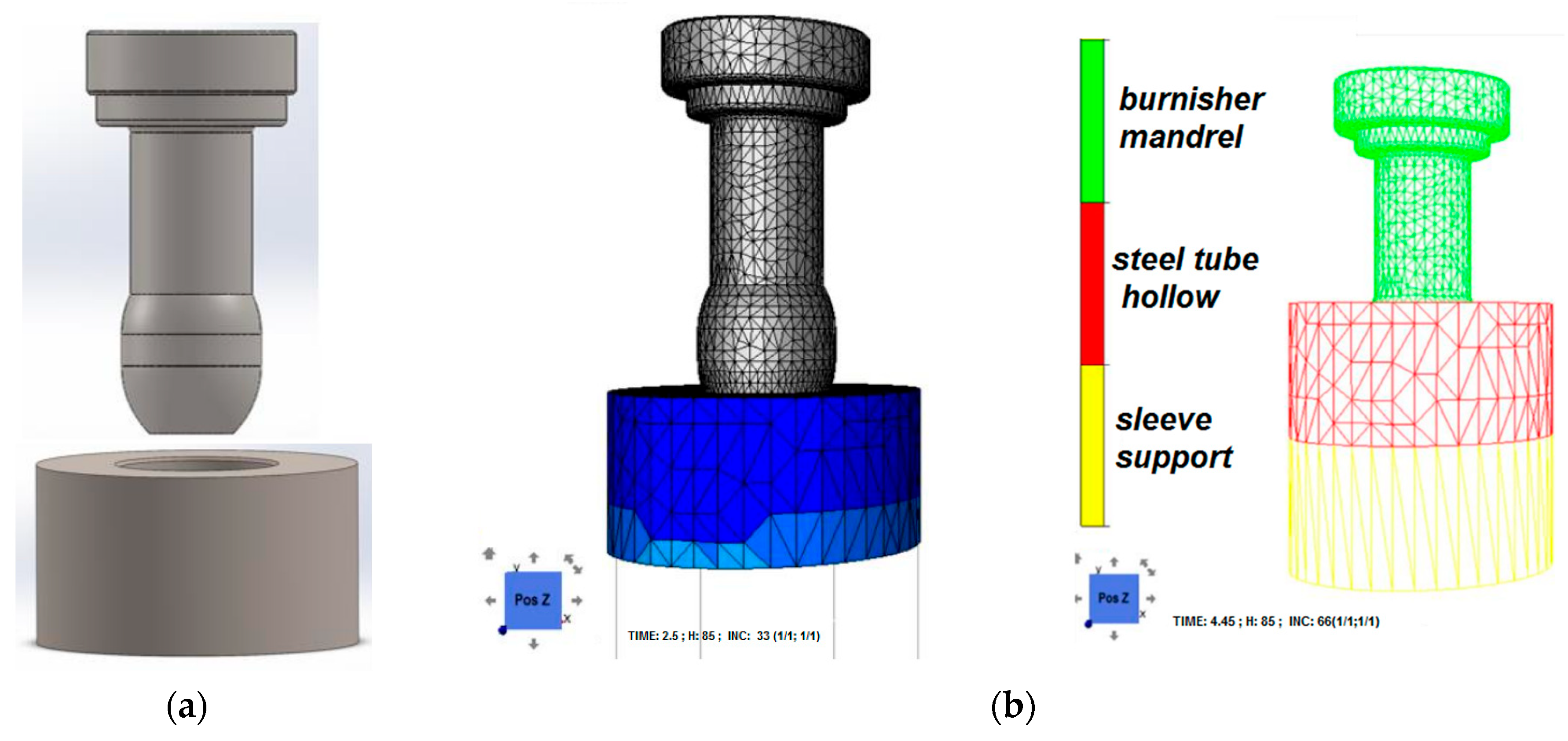
2. Numerical Analysis of Slide Burnishing Process

| Material | K0 | m1 | m2 | m3 | m4 |
|---|---|---|---|---|---|
| C45 | 1523.4 | −0.00269 | −0.12651 | 0.14542 | −0.05957 |
| 20CrMo4 | 1233.1 | −0.00254 | −0.05621 | 0.14550 | −0.03240 |
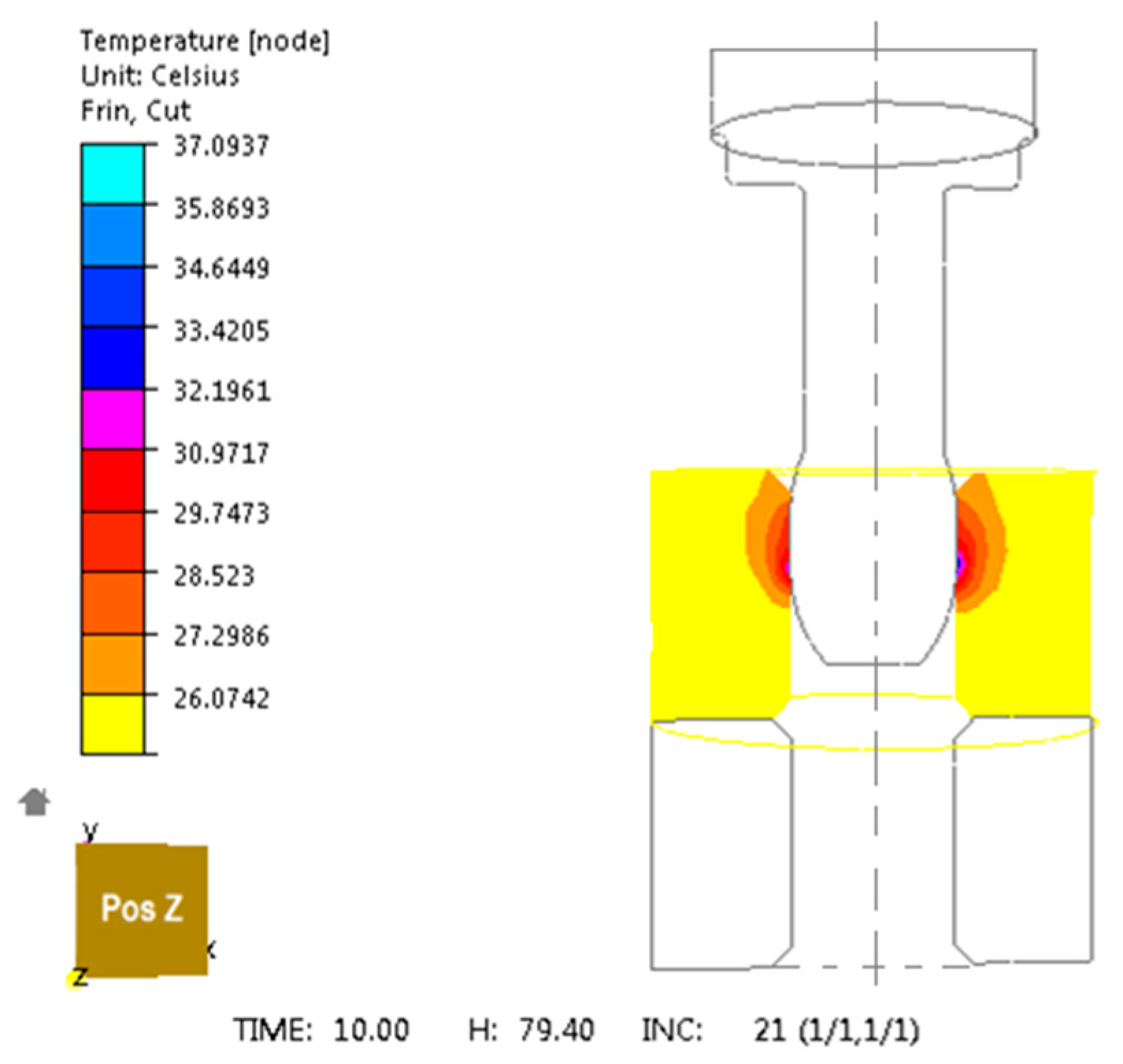
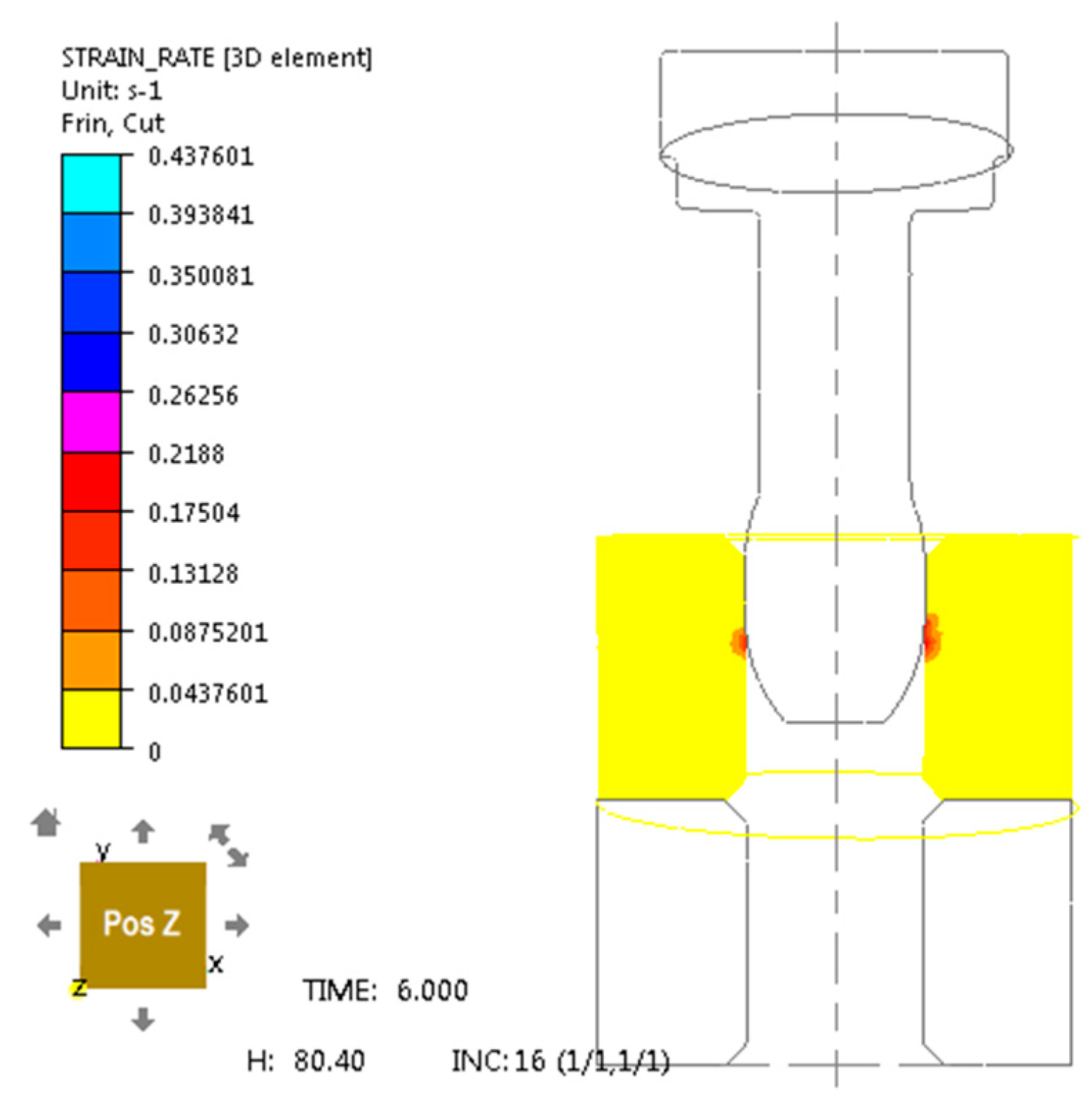
3. Research Results
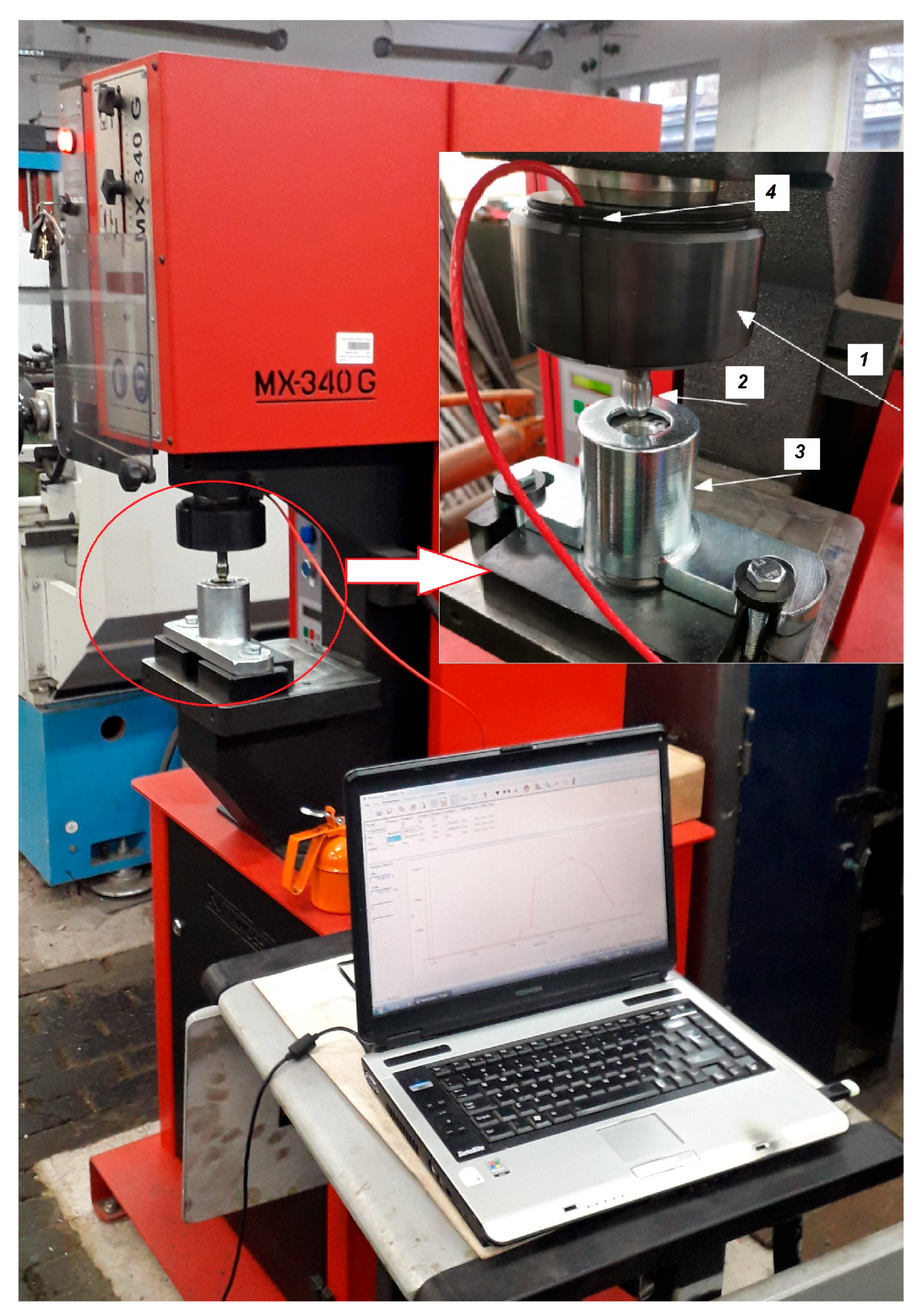
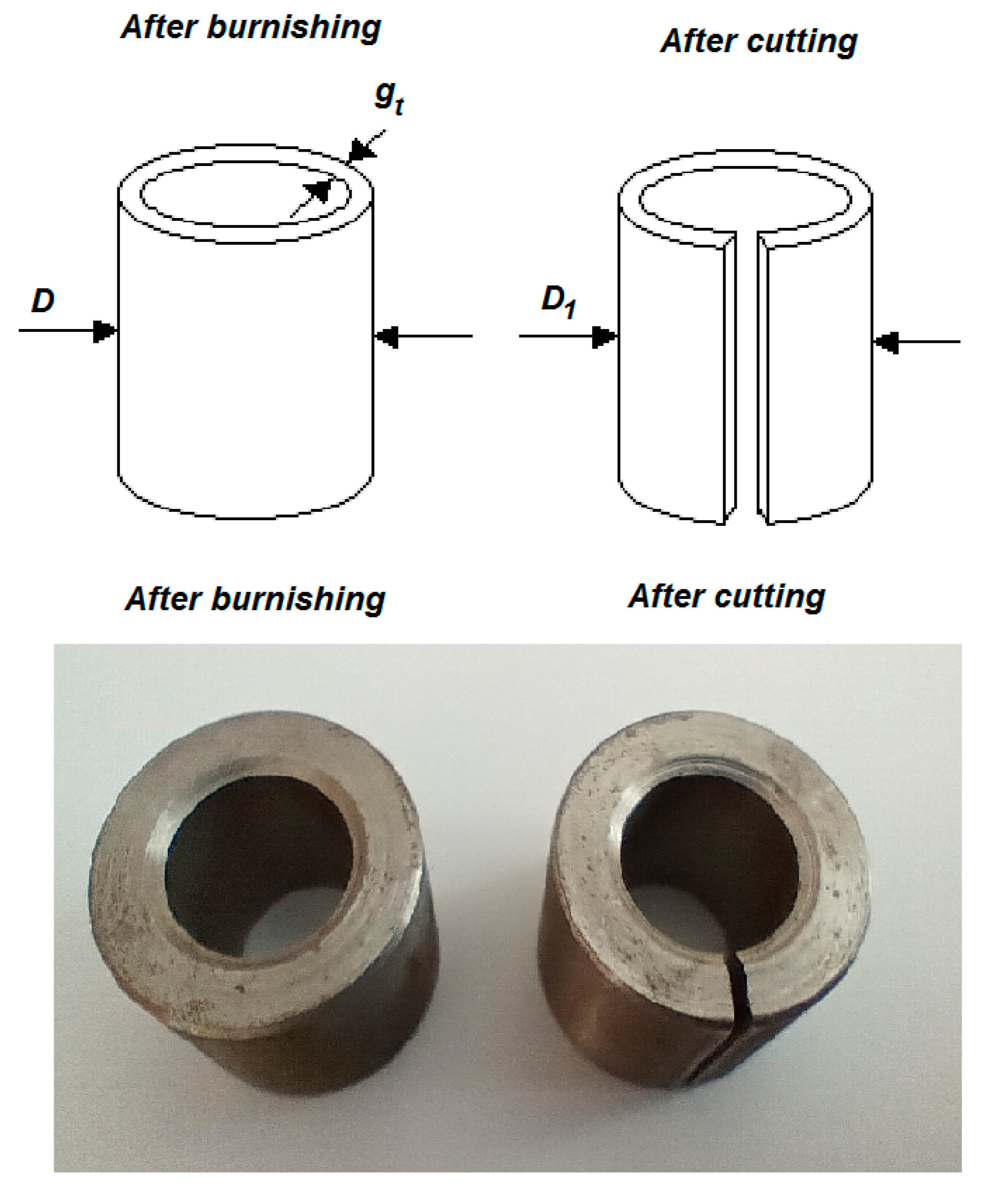
4. Experimental Verification of the Theoretical Model
- E—modulus elasticity (E = 210 GPa, for steel);
- gt—thickness of the wall [mm];
- D—outer diameter tube before slitting after burnishing [mm];
- D1—outer diameter burnishing tube and after cutting [mm].
5. Discussion
6. Summary and Conclusions
- (1)
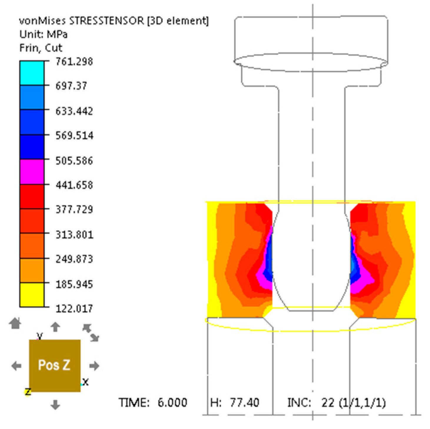
- After slide burnishing, compressive stresses are constituted in the surface layer, resulting from the increased specific volume of the material in the plastic state.
- (2)
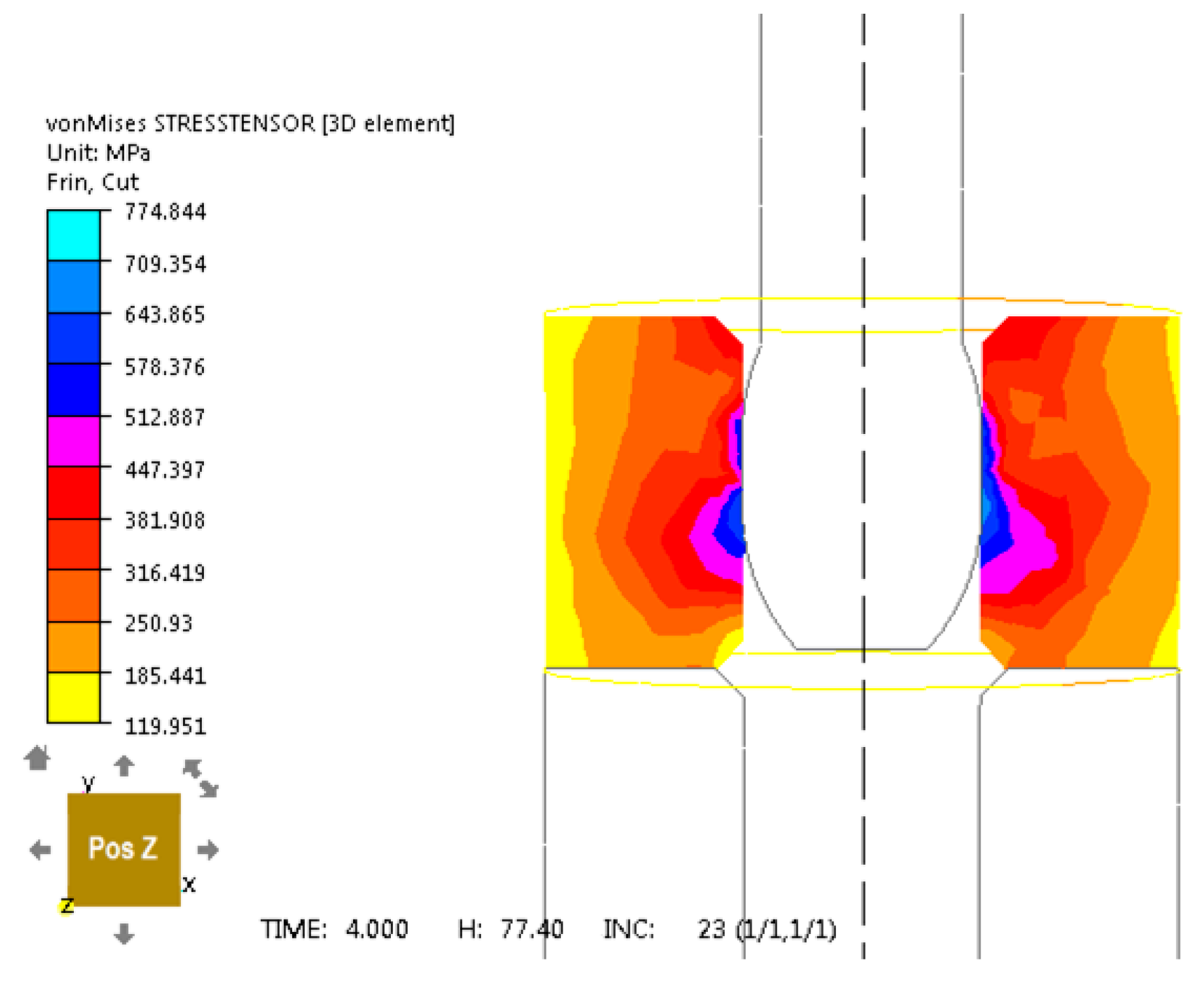
- The maximum stresses in terms of absolute value occur near the surface subjected to burnishing treatment.
- (3)
- The presence of compressive stresses in the surface layer is beneficial due to the improvement of functional properties, especially the increase in fatigue strength of machine elements, but also in tribological wear.
- (4)
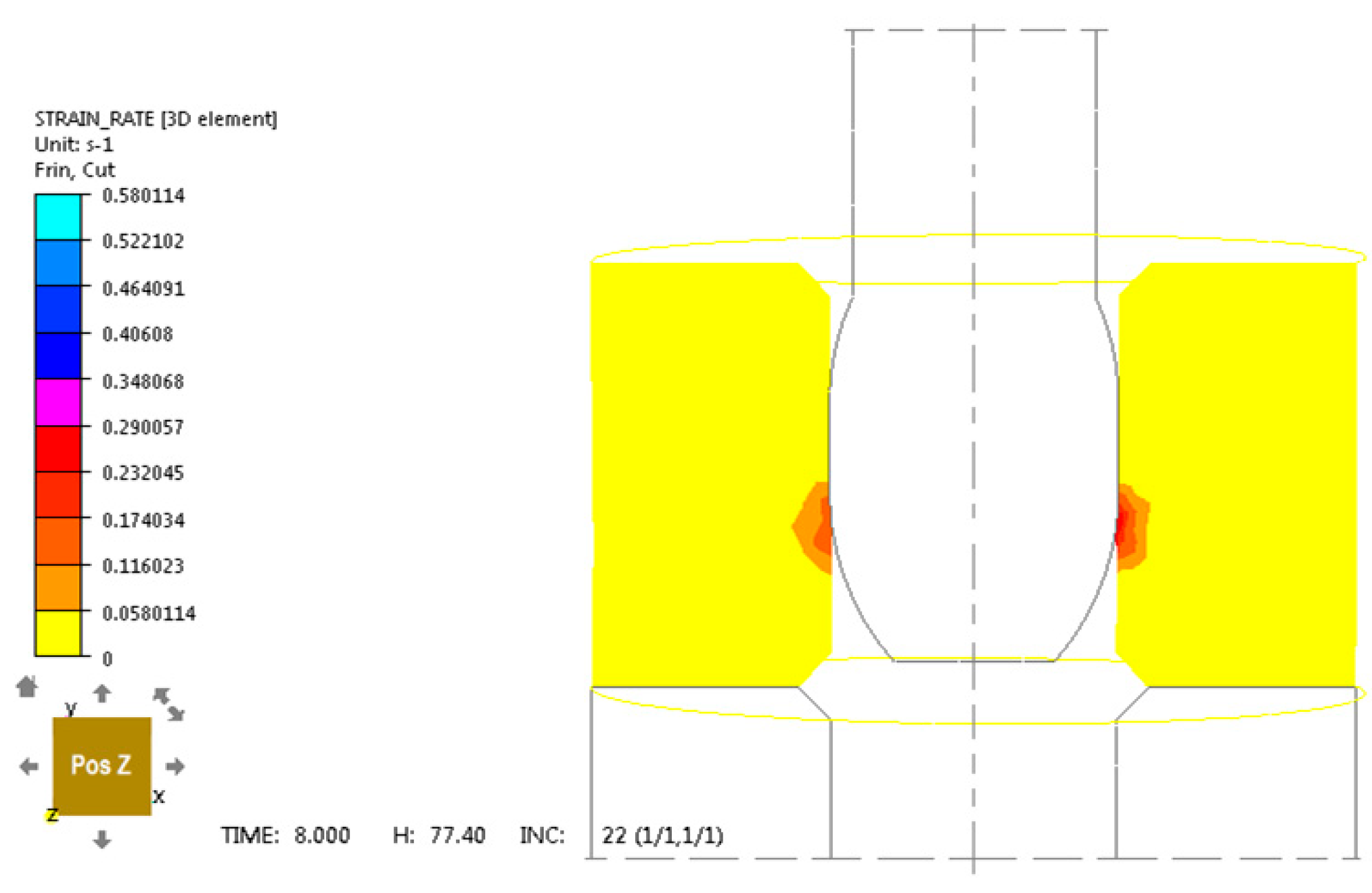
- After sliding burnishing, plastic deformations and internal stresses are constituted in the surface layer from the inside of the steel tube at a specific depth depending on the burnishing press-in.
- (5)
- It was found in numerical analysis and after experimental tests that plastic deformation occurs at a depth of approximately 20 μm to 30 μm.
- (6)
- The tubes after the experimental burnishing process were cut along the sample and the outer diameter was measured and the residual stresses were calculated. The values of residual stresses remaining in the tubes after the slide burnishing were lower than the limit value of the allowable residual stress for the mean deviation method from 35 MPa.
Author Contributions
Funding
Data Availability Statement
Conflicts of Interest
References
- Antosz, K.; Kluz, R.; Trzepieciński, T.; Bucior, M. Modeling of the influence of burnishing parameters on the surface roughness of rollers made of 42CrMo4 steel. Adv. Mech. Mater. Eng. 2022, 38, 19–29. [Google Scholar] [CrossRef]
- Becerra-Becerraa, E.; Aguilera Ojedaa, C.O.; Saldaña-Roblesb, A.; Reveles-Arredondoa, J.F.; Barco-Burgosc, J.; Vidal-Lessoa, A. A review of numerical simulation of ball burnishing process. Finite Elem. Anal. Des. 2023, 218, 103926. [Google Scholar] [CrossRef]
- Bednarski, T. Mechanika Plastycznego Płynięcia Metali; Oficyna Wydawnicza Politechniki Warszawskiej: Warszawa, Poland, 1993. [Google Scholar]
- Burakowski, T.; Wierzchoń, T. Surface Engineering of Metals: Principles, Equipment, Technologies; CRC Press LLC.: London, UK; New York, NY, USA; Washington, DC, USA, 1999. [Google Scholar]
- Doroszko, M.; Seweryn, A. A new numerical modelling method for deformation behaviour of metallic porous materials using X-ray computed microtomography. Mater. Sci. Eng. A 2017, 689, 142–156. [Google Scholar] [CrossRef]
- Dyja, H.; Banaszek, G.; Grynkevych, V.A.; Danchenko, V.N. Modelowanie Procesów Kucia Swobodnego; Monografie Politechnika Częstochowska: Częstochowa, Poland, 2004. [Google Scholar]
- Dyja, H.; Mróz, S.; Rydz, D. Technologia i Modelowanie Procesów Walcowania Wyrobów Bimetalowych; Monografie Politechnika Częstochowska: Częstochowa, Poland, 2003. [Google Scholar]
- Dyl, T. Numeryczna i Eksperymentalna Analiza Procesu Nagniatania z Wykorzystaniem Teorii Sprężystości i Plastyczności; Prace Naukowe Akademii Morskiej w Gdyni: Gdynia, Poland, 2014. [Google Scholar]
- Dyl, T.; Starosta, R.; Rydz, D.; Koczurkiewicz, B.; Kuśmierska-Matyszczak, W. The experimental and numerical research for plastic working of nickel matrix composite coatings. Materials 2020, 13, 3177. [Google Scholar] [CrossRef] [PubMed]
- Dyl, T.; Rydz, D.; Szarek, A.; Stradomski, G.; Fik, J.; Opydo, M. The Influence of Slide Burnishing on the Technological Quality of X2CrNiMo17-12-2 Steel. Materials 2024, 17, 3403. [Google Scholar] [CrossRef]
- Dzyura, V.; Maruschak, P.; Slavov, S.; Dimitrov, D.; Semehen, V.; Markov, O. Evaluating Some Functional Properties of Surfaces with Partially Regular Microreliefs Formed by Ball-Burnishing. Machines 2023, 11, 633. [Google Scholar] [CrossRef]
- Fattouh, M. Some Investigation on the Ballizing Process. Wear 1989, 134, 209–219. [Google Scholar] [CrossRef]
- Garstka, T.; Dyl, T. Circumferential residual stresses in tubes estimated by means of deflection method. Arch. Metall. Mater. 2006, 2, 199–203. Available online: https://www.imim.pl/files/archiwum/Vol2_2006/art04.pdf (accessed on 19 May 2025).
- Grochała, D.; Grzejda, R.; Józwik, J.; Siemiątkowski, Z. Improving the degree of surface isotropy of parts manufactured using hybrid machining processes. Coatings 2025, 15, 461. [Google Scholar] [CrossRef]
- Grudzień, J.; Grochała, D.; Grzejda, R.; Kochmański, P. Testing the effectiveness of hybrid milling and surface burnishing in improving the wear resistance of machine parts made of structural steel. Lubricants 2024, 12, 458. [Google Scholar] [CrossRef]
- Jerez-Mesa, R.; Fargas, G.; Roa, J.J.; Llumà, J.; Travieso-Rodriguez, J.A. Superficial Effects of Ball Burnishing on TRIP Steel AISI 301LN Sheets. Metals 2021, 11, 82. [Google Scholar] [CrossRef]
- Korzyński, M. Nagniatanie Ślizgowe; Wydawnictwo Naukowo—Techniczne: Warszawa, Poland, 2007. [Google Scholar]
- Kucharska, B. Identification of surface stress in the exhaust system pipe made by hydroforming technology based on diffractometric measurements. Eksploat. I Niezawodn.—Maint. Reliability 2019, 21, 562–566. [Google Scholar] [CrossRef]
- Kukiełka, L. Teoretyczne i Doświadczalne Podstawy Powierzchniowego Nagniatania Tocznego z Elektrokontaktowym Nagrzewaniem; Wydawnictwo Uczelniane Wyższej Szkoły Inżynierskiej: Koszalin, Poland, 1994. [Google Scholar]
- Kułakowska, A.; Bohdal, Ł. Surface Characterization of Carbon Steel after Rolling Burnishing Treatment. Metals 2024, 14, 31. [Google Scholar] [CrossRef]
- Maximov, J.; Duncheva, G.; Anchev, A.; Dunchev, V.; Anastasov, K.; Daskalova, P. Effect of Roller Burnishing and Slide Roller Burnishing on Surface Integrity of AISI 316 Steel: Theoretical and Experimental Comparative Analysis. Machines 2024, 12, 51. [Google Scholar] [CrossRef]
- Mróz, S. Proces Walcowania Prętów z Wzdłużnym Rozdzielaniem Pasma; Monograph; Monografie Politechnika Częstochowska: Częstochowa, Poland, 2008. [Google Scholar]
- Naif, A. Interaction of electric current with burnishing parameters in surface integrity assessment of additively manufactured Inconel 718. Meas. J. Int. Meas. Confed. 2024, 230, 114474. [Google Scholar] [CrossRef]
- Przybylski, W. Technologia Obróbki Nagniataniem; Wydawnictwo Naukowo—Techniczne: Warszawa, Poland, 1987. [Google Scholar]
- Ramezani, M.; Mohd Ripin, Z.; Pasang, T.; Jiang, C.P. Surface engineering of metals: Techniques, characterizations and applications. Metals 2023, 13, 1299. [Google Scholar] [CrossRef]
- Rodríguez, A.; Calleja, A.; López de Lacalle, L.N.; Pereira, O.; González, H.; Urbikain, G.; Laye, J. Burnishing of FSW Aluminum Al–Cu–Li Components. Metals 2019, 9, 260. [Google Scholar] [CrossRef]
- Rodríguez, A.; Lopez de Lacalle, L.N.; Celaya, A.; Lamikiz, A.; Albizuri, J. Surface improvement of shafts by the deep ball-burnishing technique. Surf. Coat. Technol. 2012, 206, 2817–2824. [Google Scholar] [CrossRef]
- Sachin, B.; Rao, C.M.; Naik, G.M.; Puneet, N.P. Influence of slide burnishing process on the surface characteristics of precipitation hardenable steel. SN Appl. Sci. 2021, 3, 223. [Google Scholar] [CrossRef]
- Sanchez Egea, A.J.; Rodríguez, A.; Celentano, D.; Calleja, A.; López de Lacalle, L.N. Joining metrics enhancement when combining FSW and ball-burnishing in a 2050 aluminium alloy. Surf. Coat. Technol. 2019, 367, 327–335. [Google Scholar] [CrossRef]
- Skoblik, R.; Rydz, D.; Stradomski, G. Analysis of asymmetrical rolling process of multilayer plates. Solid State Phenom. 2010, 165, 348–352. [Google Scholar] [CrossRef]
- Stradomski, G.; Rydz, D.; Dyja, H. Bimetal plate St3S+Cu. Metalurgija 2005, 44, 147–150. Available online: https://hrcak.srce.hr/file/188854 (accessed on 25 March 2025).
- Stradomski, G.; Fik, J.; Lis, Z.; Rydz, D.; Szarek, A. Wear Behaviors of the Surface of Duplex Cast Steel after the Burnishing Process. Materials 2024, 17, 1914. [Google Scholar] [CrossRef]
- Wang, Y.; Xie, M.J.; Su, C. Dynamic reliability evaluation of buried corroded pipeline under rockfall impact. Eksploat. I Niezawodn.—Maint. Reliab. 2022, 24, 275–288. [Google Scholar] [CrossRef]
- Winiarski, G.; Gontarz, A.; Skrzat, A.; Wójcik, M.; Wencel, S. Analysis of a New Process for Forming Two Flanges Simultaneously in a Hollow Part by Extrusion with Two Moving Dies. Metals 2024, 14, 612. [Google Scholar] [CrossRef]
- Yin, D.; Zhao, H.; Chen, Y.; Chang, J.; Wang, Y.; Wang, X. Modification of Johnson–Cook Constitutive Parameters in Ball Burnish Simulation of 7075-T651 Aluminum Alloy. Metals 2023, 13, 1992. [Google Scholar] [CrossRef]
- Zaleski, K. Technologia Nagniatania Dynamicznego; Wydawnictwo Politechniki Lubelskiej: Lublin, Poland, 2018. [Google Scholar]
- Zaleski, K.; Lipski, J. Modelling on the Ballizing Process of Holes in Workpieces Made of C45 Steel; Management and Control of Manufacturing, Processes; Świć, A., Lipski, J., Eds.; Lubelskie Towarzystwo Naukowe: Lublin, Poland, 2011; pp. 114–124. [Google Scholar]
- FORGE® Reference Guide Release; Transvalor S.A., Parc de Haute Technologie, Sophia–Antipolis: 2024. Available online: https://www.transvalor.com/en/forge (accessed on 24 September 2024).
- Walton, H.W. Deflection Methods to Estimate Residual Stress. In Handbook of Residual Stress and Deformation of Steel; Totten, G., Howes, M., Inoue, T., Eds.; ASM International: Materials Park, OH, USA, 2002; pp. 89–98. [Google Scholar]
- Zhang, D.; Zhang, X.M.; Ding, H. Experimental and Numerical Study of the Subsurface Deformation and Residual Stress during the Roller Burnishing Process. Procedia CIRP 2020, 87, 491–496. [Google Scholar] [CrossRef]


| Material | C [%] | Mo [%] | Mn [%] | Cr [%] | Si [%] | P [%] | S [%] | Fe [%] |
|---|---|---|---|---|---|---|---|---|
| C45 | 0.45 | 0.1 | 0.6 | 0.4 | 0.4 | 0.04 | 0.04 | Balance |
| 20CrMo4 | 0.40 | 0.2 | 0.7 | 1.2 | 0.3 | 0.03 | 0.03 | Balance |
Disclaimer/Publisher’s Note: The statements, opinions and data contained in all publications are solely those of the individual author(s) and contributor(s) and not of MDPI and/or the editor(s). MDPI and/or the editor(s) disclaim responsibility for any injury to people or property resulting from any ideas, methods, instructions or products referred to in the content. |
© 2025 by the authors. Licensee MDPI, Basel, Switzerland. This article is an open access article distributed under the terms and conditions of the Creative Commons Attribution (CC BY) license (https://creativecommons.org/licenses/by/4.0/).
Share and Cite
Dyl, T.C.; Kuśmierska-Matyszczak, W. The Effect of the Burnishing Process on the Strain Rate and State Stress in Hollow Steel Tubes. Metals 2025, 15, 694. https://doi.org/10.3390/met15070694
Dyl TC, Kuśmierska-Matyszczak W. The Effect of the Burnishing Process on the Strain Rate and State Stress in Hollow Steel Tubes. Metals. 2025; 15(7):694. https://doi.org/10.3390/met15070694
Chicago/Turabian StyleDyl, Tomasz Cyryl, and Wioletta Kuśmierska-Matyszczak. 2025. "The Effect of the Burnishing Process on the Strain Rate and State Stress in Hollow Steel Tubes" Metals 15, no. 7: 694. https://doi.org/10.3390/met15070694
APA StyleDyl, T. C., & Kuśmierska-Matyszczak, W. (2025). The Effect of the Burnishing Process on the Strain Rate and State Stress in Hollow Steel Tubes. Metals, 15(7), 694. https://doi.org/10.3390/met15070694