Abstract
For over five decades, blending hydrogen into existing natural gas pipelines has been explored as a potential solution to reduce greenhouse gas emissions. Despite its promise, implementing this approach has been slow due to concerns about hydrogen embrittlement (HE) and its interactions with various metals. Stainless steel alloys like 316L are commonly used in hydrogen service due to their superior resistance to HE. However, the impact of additive manufacturing (AM) on 316L’s susceptibility to HE when subjected to gas charging has not been thoroughly investigated. To fill this knowledge gap, we created conventionally manufactured and AM 316L tensile bars and solubility specimens, which were then exposed to hydrogen-blended natural gas at 10 MPa with a 50% blend and 100% pure H2. Both conventionally manufactured and additively manufactured specimens had as-received/printed samples that were used as controls. The samples underwent mechanical evaluation through tensile testing and hot chemical extraction to assess hydrogen solubility. Further analysis revealed significant changes in the microstructure near the fracture area of the soaked samples using scanning electron microscope fractography and metallography. These findings were compared with our previous work on traditionally produced 316L bar stock, which demonstrated that AM processing conditions can yield superior performance in terms of resistance to HE. Notably, this study provides valuable insights into the effects of AM on 316L’s susceptibility to HE when subjected to gas charging. The results have significant implications for the development and implementation of AM 316L for hydrogen/natural gas applications in pressure regulators when AM processing conditions are well-controlled. This article is a revised and expanded version of a paper entitled “Effect of Hydrogen-Blended Natural Gas on Additive Manufactured 316L Stainless Steel in Pressure Regulator Environments”, which was presented at TMS in Las Vegas, March 2025.
1. Introduction
The past several decades have seen an increase in the investment of renewable energy sources, such as electric vehicles, solar power, and nuclear power plants, into existing infrastructure [1,2,3], but this has been hindered by a lack of adoption in the United States due to infrastructure limitations and negative stigmas [4,5]. However, a potential cost-effective solution to reduce greenhouse gas (GHG) emissions is to create a hydrogen economy by blending hydrogen into existing natural gas pipeline infrastructure, and this is projected to produce 14% of the U.S. energy needs by 2050 [6]. Despite its promise, the concern of gaseous hydrogen embrittlement (HE) in metallic materials has prevented immediate adoption [7]. Fortunately, extensive research on HE as early as the 1970s has been conducted on synthetic natural gas pipelines using up to a 12% blend of hydrogen [8]. This study and others have shown that there is some compatibility with existing materials at low pressures (much less than 1 MPa) and low concentrations (less than 20% hydrogen partial pressure) [8,9,10]. However, further research is required to understand HE at higher pressures and concentrations in new materials and manufacturing methods before the widespread adoption of a hydrogen economy.
Additive manufacturing (AM) has increasingly been used across various sectors, including the oil and gas industry, to create cost-effective solutions with reduced lead times and disruptive design possibilities such as lattice structures using design for additive manufacturing (DfAM) strategies [11,12]. Some companies have started using AM parts with DfAM, such as ball valves with unique designs in natural gas lines made of 316L stainless steel [13]. However, additively manufactured metals have not been extensively studied for industrial implementation yet, especially in hydrogen service. Although there are several long-term studies on HE in traditional low-alloy pipeline steels [8,9,14,15] and some data on stainless steels [16,17,18], few studies have investigated the effect of HE on AM 316L stainless steel [19]. To date, most research has focused on very high pressures (greater than 50 MPa) and temperatures (above 200 °C) [20,21,22] or used electrochemical charging for accelerated HE effects [23,24]. Furthermore, electrochemical charging studies are generally not suitable for comparison as previous works have concluded that the mechanism of hydrogen adsorption and overall effects are different from gaseous charging [8,25,26].
To address this knowledge gap, this study aims to investigate the interaction between hydrogen inside an AM 316L microstructure and compare the results with the performance of conventionally manufactured (CM) 316L. This work focuses on irreversibly trapped hydrogen in the microstructure to predict real-world conditions that AM 316L parts might experience in the oil and gas industry. These are most commonly pressure lines less than 10 MPa with ambient temperatures in the range of 10–45 °C [27]. Previous research indicates that there can be significant differences in pipeline temperatures and gas conditions along the line, motivating as close to real-world condition testing as possible [28]. There are considerable differences between CM and AM, where AM parts generally have highly anisotropic properties to address that require a subsequent heat treatment [29]. These differences are vital to understand as HE sensitivity and the mechanisms of failure have proved to be related to microstructures with features such as retained austenite, grain size, and grain boundaries that can act as hydrogen traps [30]. This study builds upon previous work, which showed a reduction in ductility and tensile strength when the sample was completely saturated with hydrogen and tested in situ [21]. This study investigates the mechanical response of AM 316L to hydrogen exposure due to the manufacturing method after all reversable hydrogen has been allowed to leave the system. The goal is to develop new procedures and standards for the use of additively manufactured metals in hydrogen service. The research focuses on the mechanisms of hydrogen-enhanced localized plasticity (HELP), possible hydride formation, and cleavage as these mechanisms are likely to be relevant to AM 316L parts in service. The study contributes to the understanding of HE in AM 316L stainless steel and its application in the oil and gas industry.
2. Materials and Methods
CM 316L was bought in bar form and analyzed via positive material identification (PMI). The chemical composition of the CM 316L bar stock is listed in Table 1 and compared with the AM 316L powder feed stock (supplier 6K additive). The AM feed stock exhibited particle sizes in the range of 5–50 μm and parts were made by laser-bed powder fusion (LBPF) using an EOS M290 printer. Standard print parameters from EOS for regulator parts were used with a power of 212 W, speed of 928 mm/s2, layer height of 0.4 mm, and hatch spacing of 0.1 mm. Cylinders were built in the vertical (build) direction with a height of 85 mm and a diameter of 18 mm. Only the vertical build direction was considered because our previous work showed that tensile bars built in the build direction have the greatest ductility of any orientation, therefore, any change in ductility because of HE is easier to identify [31]. After printing, all parts were taken to a refractory resistor heated furnace to be stress-relieved for 1 h at 400 °C before being cut off the build plate by a band saw as per standard operating procedures.

Table 1.
Chemical composition of the as-received CM 316L bar stock and printed AM 316L bars ascertained by PMI.
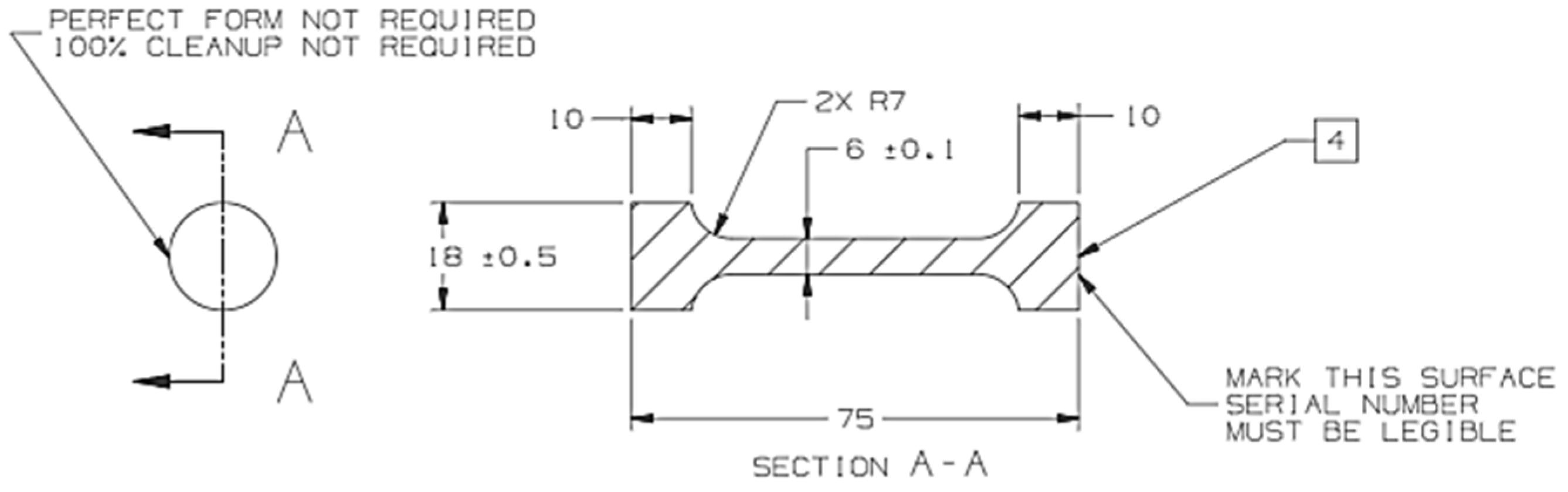
Figure 1 shows the drawing used for machining the tensile bars for both the CM and AM 316L bars. CM 316L bars were turned down from an initial diameter of 25 mm to eliminate surface hardening effects before being machined into tensile samples. Solubility samples were also machined from the bars in the shape of half circles with a thickness of approximately 2.5 mm and a diameter of 18 mm from the ends of the tensile bars. This shape was created to fit into the glass tube of our hydrogen analyzer after soaking. Three tensile samples and four solubility samples were made per soaking condition, as shown in Table 2. Soaking concentrations were chosen with a realistic implementation of hydrogen, with expected maximum blend (50%) and extreme (100%) conditions to be tested [32]. All tensile and solubility samples were polished to remove any oxide layers, ultrasonically cleaned, and then placed into a 3D-printed ABS holding structure in vacuum-sealed bags to prepare the samples for soaking (Figure 2a). The 3D-printed ABS holding structure with 3 tensile bars and 4 solubility samples was then placed into carbon steel metal tubes and exposed to the specified hydrogen blend, pressure, and duration in an outdoor setting, as shown in Figure 2b.

Figure 1.
Schematic drawing of the tensile bar machined from bar stock for mechanical testing per ESTM E8.
Table 2.
Pressure, hydrogen concentration, and testing interval for both CM 316L and AM 316L tensile and solubility samples.
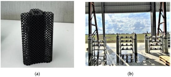
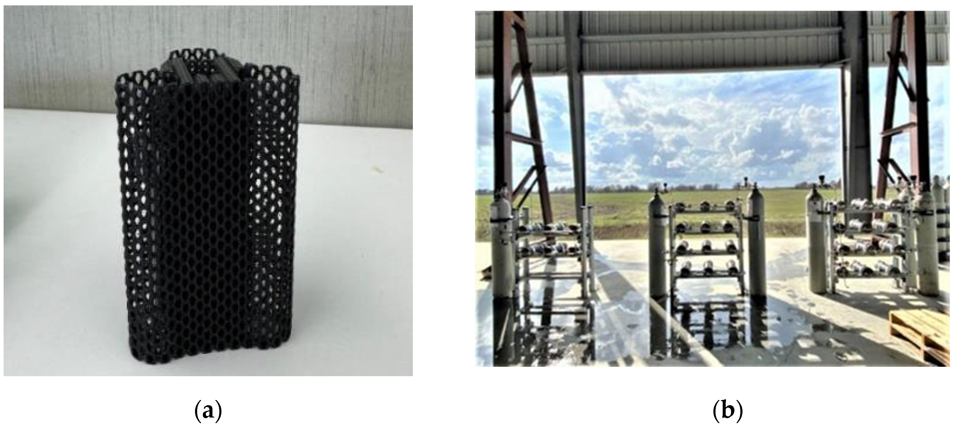
Figure 2.
(a) The 3D-printed ABS holding structure for 3 tensile bars and 4 solubility samples in the center of the fixture. (b) Field-testing set-up of steel canister holding fixtures. The ABS holding structure was loaded with samples and then placed in the steel canister holding fixture.
After soaking, all tensile and solubility samples were allowed to rest for at least 72 h to allow all reversable hydrogen to degas in the lab at room temperature. Tensile tests were performed at an ambient temperature according to ASTM E8 on a 60,000 lbf (300 kN) Capacity United, Model FM-60, computer-controlled testing machine [33]. The data acquisition rate was approximately 5 data point pairs per second and was pulled at a rate of 5 mm/min to 0.02% strain and then increased to 15 mm/min until failure. Fractography was performed using Hitachi S-3400N Scanning Electron Microscopy (SEM) equipment and light microscopy was used to analyze the mounted and polished samples after SEM fractography.
Residual hydrogen measurements were carried out using an Eltra H-500 hydrogen determinator and a hot extraction method (Figure 3). Extraction was carried out at 1000 °C under high-purity nitrogen and helium for fast hydrogen analysis extraction, as per the manufacturer recommendations, to determine the parts per million of hydrogen in each sample.
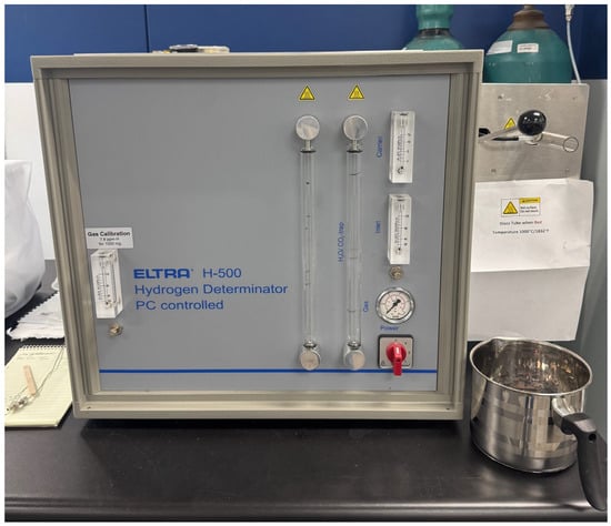
Figure 3.
Eltra H-500 hydrogen analyzer used for analyzing hydrogen ppm in hydrogen solubility samples.
3. Results and Discussions
3.1. Mechanical Response
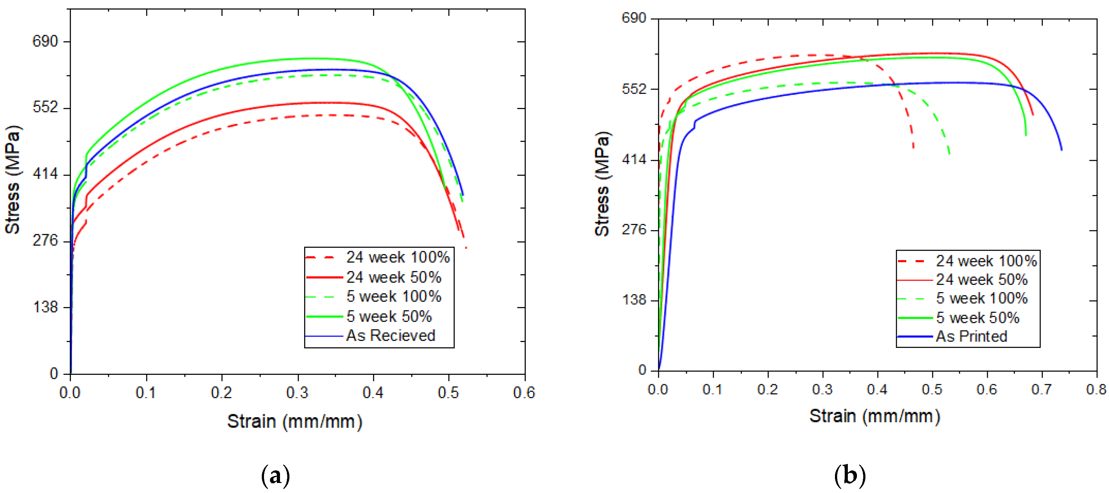
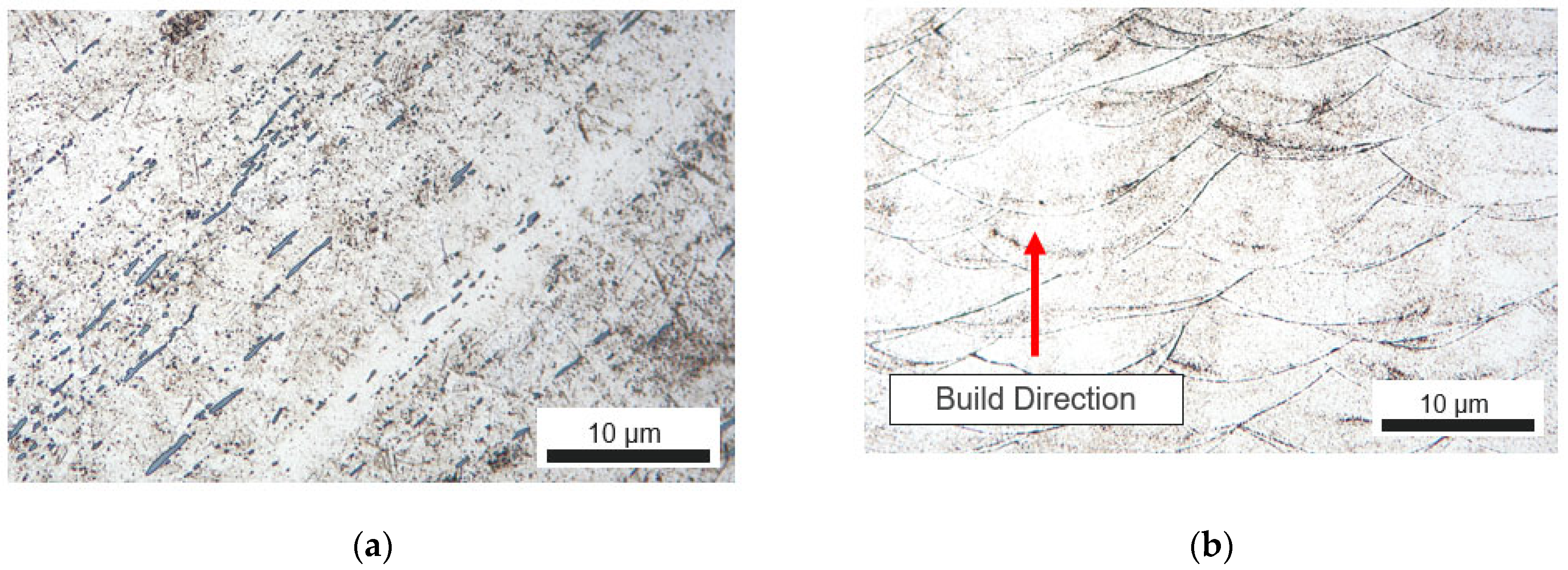
Tensile testing revealed a change in the ductility and yield strength between the two manufacturing methods, with representative graphs for only a single run from each condition shown in Figure 4. The AM 316L bars exhibited higher ductility and yield strength in all conditions (Figure 4), likely due to the unique and highly anisotropic microstructure of the AM process, as shown in Figure 5, which shows the microstructure of (a) a CM 316L bar and (b) an AM bar after stress relief. This columnar growth allowed the material to undergo more plastic deformation than the CM samples.
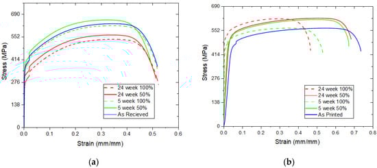
Figure 4.
Representative tensile curves for (a) CM vs. (b) AM 316L stainless steel tensile bars for the as-received/printed state and the soaking conditions at 5 weeks and 24 weeks in 50% and 100% hydrogen.
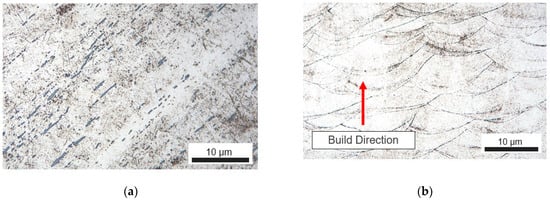
Figure 5.
Microstructure of (a) a CM 316L bar vs. (b) an AM 316L bar after stress relief, highlighting the differences in grain shape and size due to the manufacturing method.
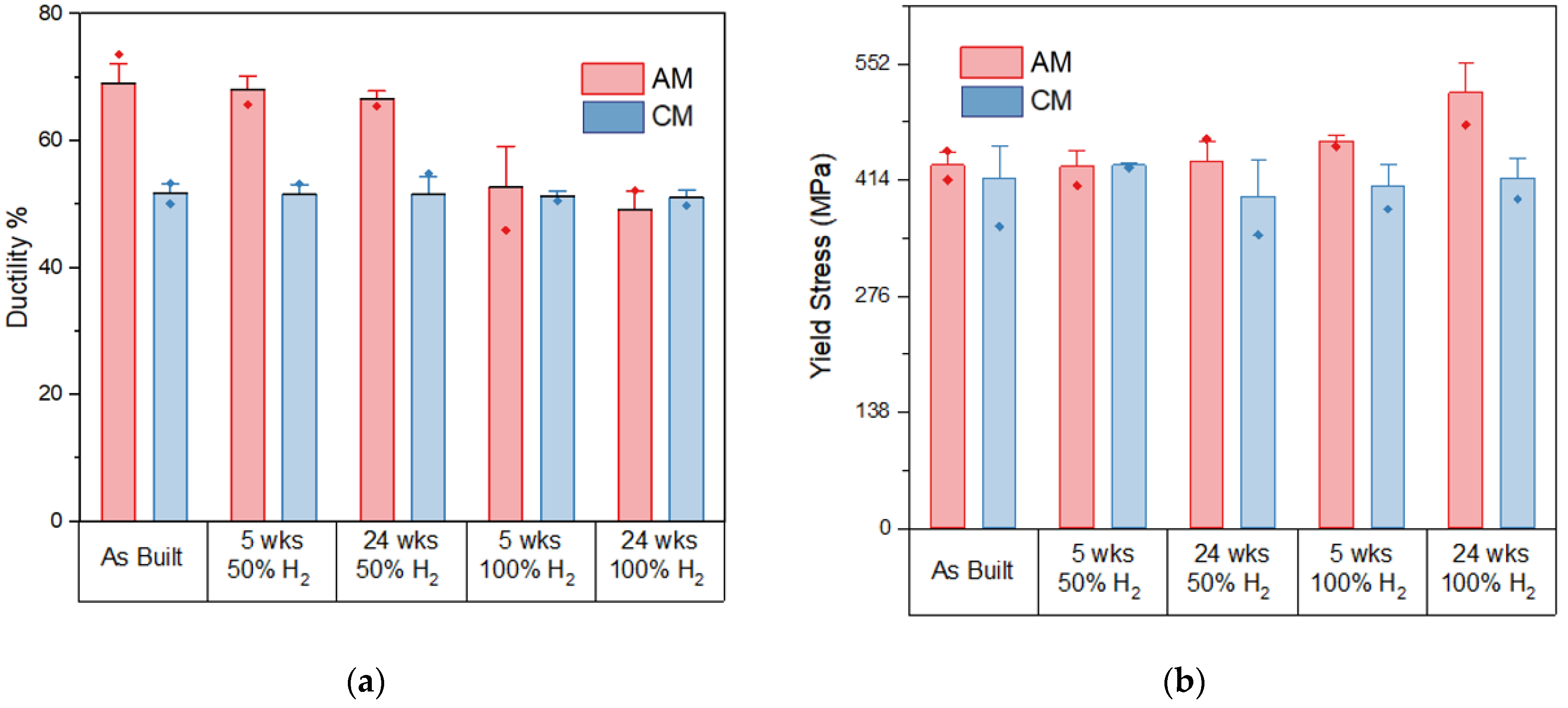
The mechanical properties showed a significant difference in the ductility and yield strength response of the material after being soaked in hydrogen for the two manufacturing methods. Both methods showed little change to being soaked in the 50% (5 MPa partial pressure) hydrogen across all time intervals; however, the AM samples showed a noticeable reduction in ductility for the 100% soak condition after 5 weeks and 24 weeks (Figure 6) and a slight increase in yield strength, indicative of gaseous HE [8]. The CM samples continued to show no response at 24 weeks, which agrees with results from previous works performed in even more extreme hydrogen charging [34], further proving 316L’s resistance to hydrogen due to low diffusivity through the austenite microstructure due to a high Ni weight percent. The slight variation observed in the CM samples was likely due to impurities in each sample [35] and we did not experience any corresponding increase in hydrogen across any time or concentration.
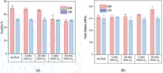
Figure 6.
(a) Average ductility and (b) average yield stress of AM 316L samples compared with CM 316L samples from no hydrogen soaking to 24 weeks of 100% hydrogen. The dot on each bar represents the largest outlier with the error bar based on standard deviation.
3.2. Chemical Analysis
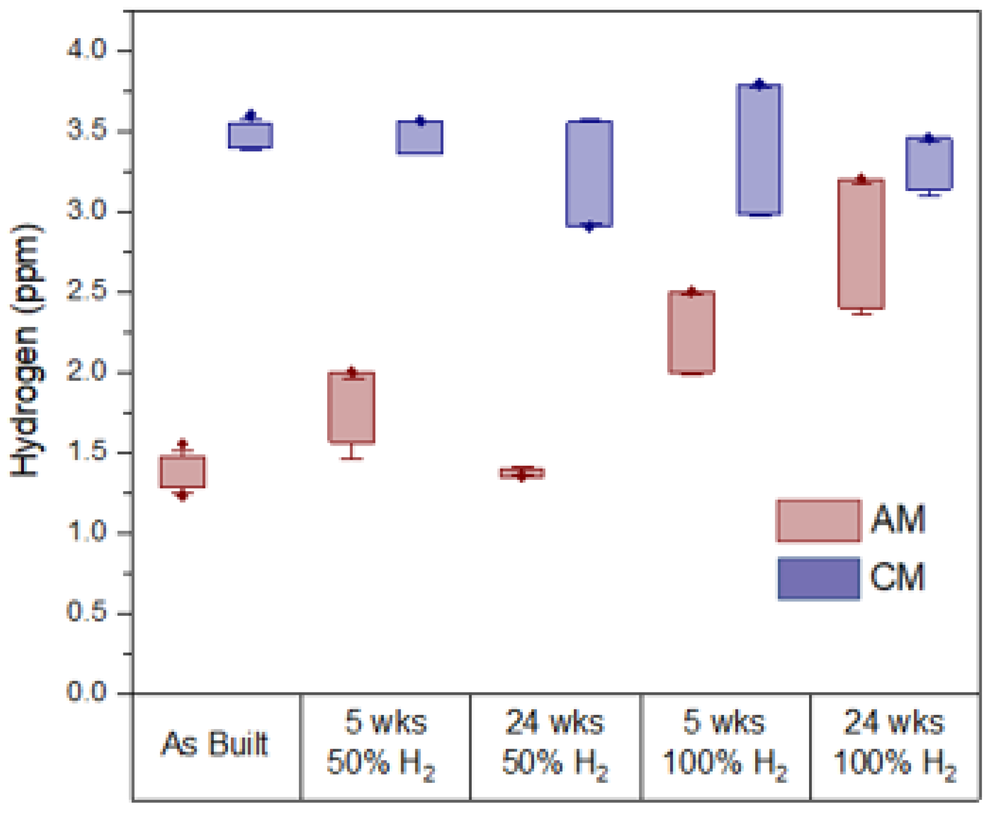
Hot chemical extraction supported the observation that some HE occurred in the AM samples soaked in 100% hydrogen, while there was little change in the hydrogen content in the CM samples to indicate HE. The CM solubility samples were found to have larger amounts of hydrogen than the AM solubility samples in all conditions. The AM samples showed considerably less hydrogen in the as-printed condition compared with the CM samples. However, with increasing concentrations of hydrogen and soak times, there was a corresponding increase in the hydrogen ppm, summarized in Figure 7. The relatively high amounts of residual hydrogen regardless of the soak method in the CM samples was likely due to the higher amount of nonmetallic material (Mn and S), which act as high-energy trapping sites in a composition, compared with the AM samples (Table 1) [36]. These nonmetallic inclusions act as high-concentration hydrogen traps in the foundry process, as found in our previous work [35]. The AM samples did not have these inclusions as the AM process is less prone to such inclusions when working with very high-quality powder compared with the billets in castings [37]. The solubility samples, therefore, acted as small-sample representations of the tensile samples that could not fit into the hydrogen analyzer or be cut to fit for fear of losing hydrogen in the process.

Figure 7.
Hydrogen chemical analysis of AM (red) vs. CM (blue) 316L solubility samples per soak condition.
3.3. Fractography and Microstructure Analyses
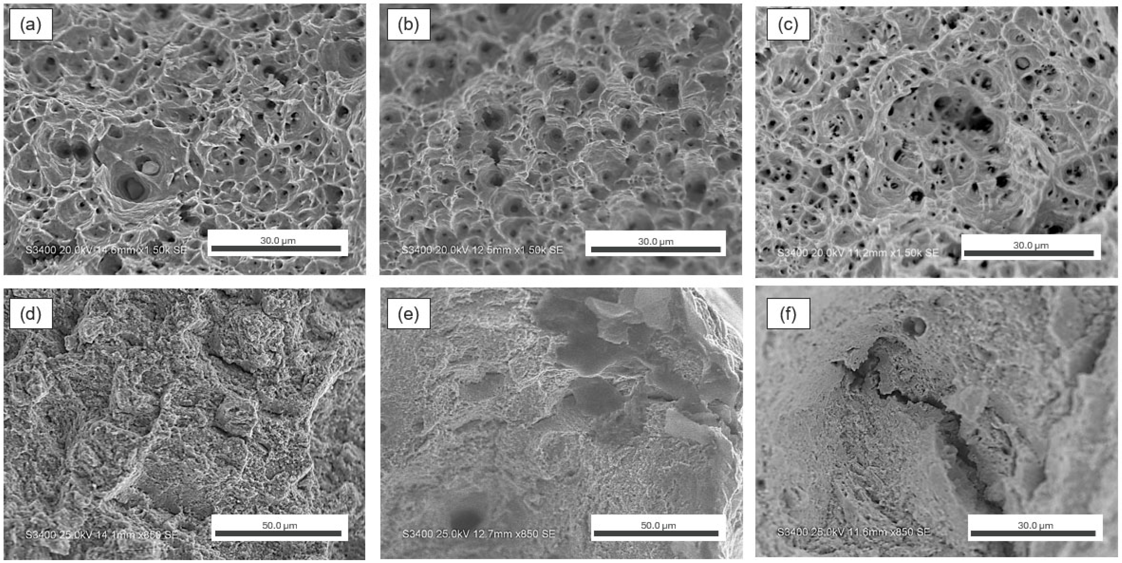
The combination of SEM fractography and microscopy helped to explain why HE likely occurred in the AM samples and not in the CM samples. After soaking, there was no apparent change in the overall fracture surface of the CM bars from as-received to the harshest condition (24 weeks and 100% hydrogen; Figure 8a,b). All CM bars were observed to maintain ductile fracture characteristics throughout the fracture surface, with no features consistent with HE observed. In contrast, the AM bars showed two different responses. The bars soaked in the 50% H2/natural gas blend showed no change, which is similar to the CM samples shown in Figure 8. The bars soaked in 100% H2 showed some regions of potentially brittle fractures and a reduction in the area characterized by a now-oval cross-section (Figure 8d). Other research has indicated that the change in cross-section is a result of uneven loading in the grain structure by transformation-induced plasticity (TRIP) that is enhanced due to hydrogen adsorption in retained austenite phases, increasing the fraction of the brittle martensite phase [38]. Figure 9 shows the representative higher-magnification SEM fractography images from the CM and AM samples across the relevant conditions. Characteristics of ductile failure mode, such as dimples, were observed throughout the surface of all samples in all soak conditions, most notably for the AM bars in the 50% hydrogen soak (with characteristics like the as-printed condition shown in Figure 9d). However, the AM tensile bars soaked in the extreme 100% hydrogen soak condition showed significant areas of quasi-cleavage fracture indicative of a brittle failure mode (Figure 9e) commonly found in HE as well as large internal cracks near the edge of the sample (Figure 9f) that were not found in any of the CM samples (Figure 10a–c). This failure mode is commonly associated with HE and intergranular cracking, indicating that enough areas were made brittle by hydrogen adsorption, leading to the reduction in ductility observed in Figure 6 in the 100% hydrogen soak.
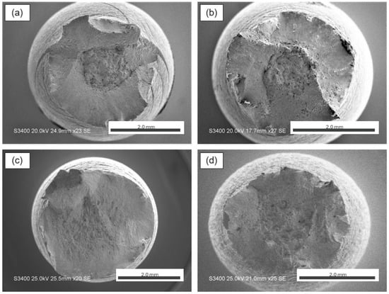
Figure 8.
SEM images of the fracture surface of tensile bars after testing: (a) as-received and (b) soaked for 24 weeks in 100% hydrogen in the CM 316L condition; (c) as-printed and (d) soaked for 24 weeks in 100% hydrogen in the AM 316L condition.

Figure 9.
High-magnification fractography images of representative areas for samples: (a) as-received, (b) 50% hydrogen for 24 weeks, and (c) 100% hydrogen for 24 weeks for CM 316L (top); (d) as-printed, (e) 100% hydrogen for 5 weeks, and (f) 100% hydrogen for 24 weeks for AM 316L (bottom) after stress relief. Images were taken near the center of the sample to avoid any edge effects.

Figure 10.
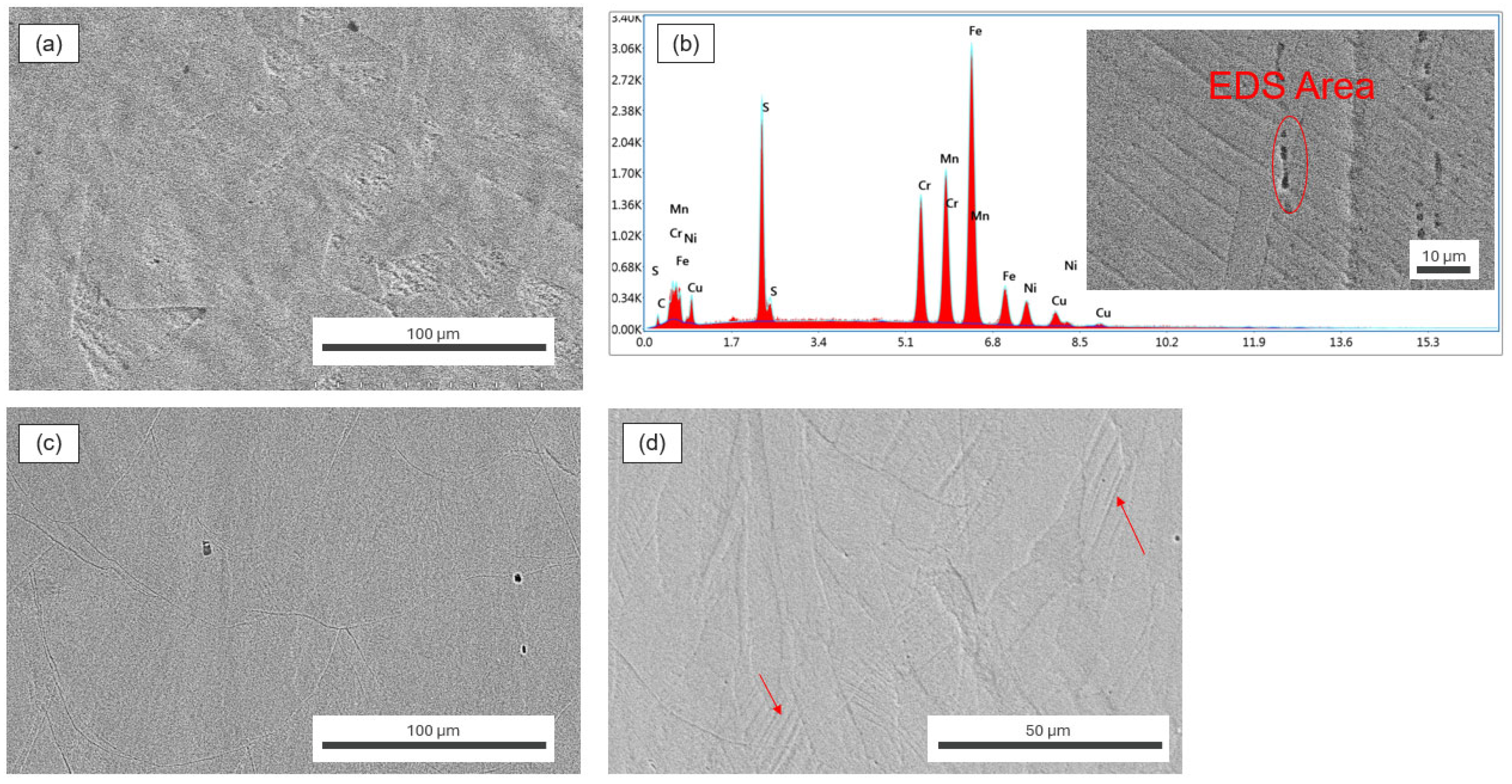
SEM comparison of (a) CM 316L with (b) EDS of a site with many MnS inclusions compared with (c) AM 316L with a close-up (d) showing the small columnar grain and some potential subgrain cellular structures, with arrows highlighting deformation lenticular twins after tensile testing.
SEM imaging of the microstructure highlighted the difference between the two manufacturing methods. The CM samples exhibited a typical microstructure of small (<15 μm) equiaxed grains, while the AM samples retained their small and columnar grains (<10 μm) after the 1 h heat treatment based on our previous work [39]. EDS on the CM samples revealed the composition of nonmetallic inclusions that were seen in all samples, with the majority being MnS (Figure 10b). These inclusions, not present in the AM samples, acted as high-energy traps for hydrogen, thus enabling the CM samples to have more hydrogen than the CM samples in such low hydrogen diffusion conditions [36]. The refined and anisotropic structure with the subcellular structure in the microstructure led to the difference in mechanical response, as observed in Figure 6. A small grain size has been seen to increase yield strength via the Hall–Petch relationship and subgrain structures allow for increased ductility, promoting the formation of more strain-induced martensite (SIM), which can help to promote TRIP in AM steels. Although these unique features have been theorized to help mitigate HE by creating more reversible traps and slowing diffusion [40], or by promoting it with increased SIM by increased deformation twins, neither of these phenomena [41] were characterized in-depth in this work. In Figure 10b,d, twinning can be found because of deformation from the tensile testing in both CM and AM 316L. Instead, the focus was turned to the porosity of the AM samples as these defects were the most likely abundant trapping sites to hold hydrogen.
Light microscopy showed that despite having a print density of approximately 99% [35], voids were present in all the AM tensile samples fractured in this study (Figure 11a). No large voids were found in any of the CM samples with microstructures, but instead they were found to have many nonmetallic inclusions identified to be mostly MnS (Figure 11b) and supported by the PMI analysis in Table 1. The voids likely acted as hydrogen accumulation regions inside the bulk of the material that remained even after the samples were allowed to sit for 72 h, particularly voids that were near the edge of the sample, which allowed for large internal cracking (Figure 11c). This phenomenon was only found in the 100% hydrogen concentration as the diffusion and concentration of hydrogen at the surface of the AM samples was great enough to reach voids in high enough quantities to cause a brittle failure not observed in the 50% concentration. Equation (1) highlights that with a simple partial pressure estimation, where K is the spontaneous dissociation percentage of atomic hydrogen, less than 1 MPa of atomistic hydrogen will spontaneously form at the given condition. In the blend condition, our previous work and other studies have shown some evidence that CH4 and CO mixing can limit the harmful effects of HE in pipeline steels by lowering the penetrative power of H2 more than expected, which likely explains why no HE was observed in the 50% soak condition, essentially creating a shielding effect from the natural gas [42]. Using basic diffusion from Fick’s second law (Equation (2)), the increased embrittlement with increased time can also be explained. Assuming a constant hydrogen concentration at the surface in the 100% H2 condition, a greater concentration depth of diffusion into the sample with time was expected, as observed in Figure 4.
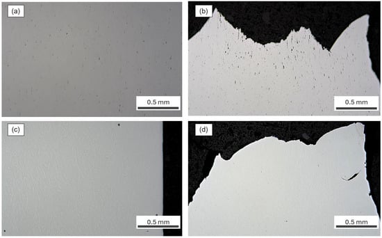
Figure 11.
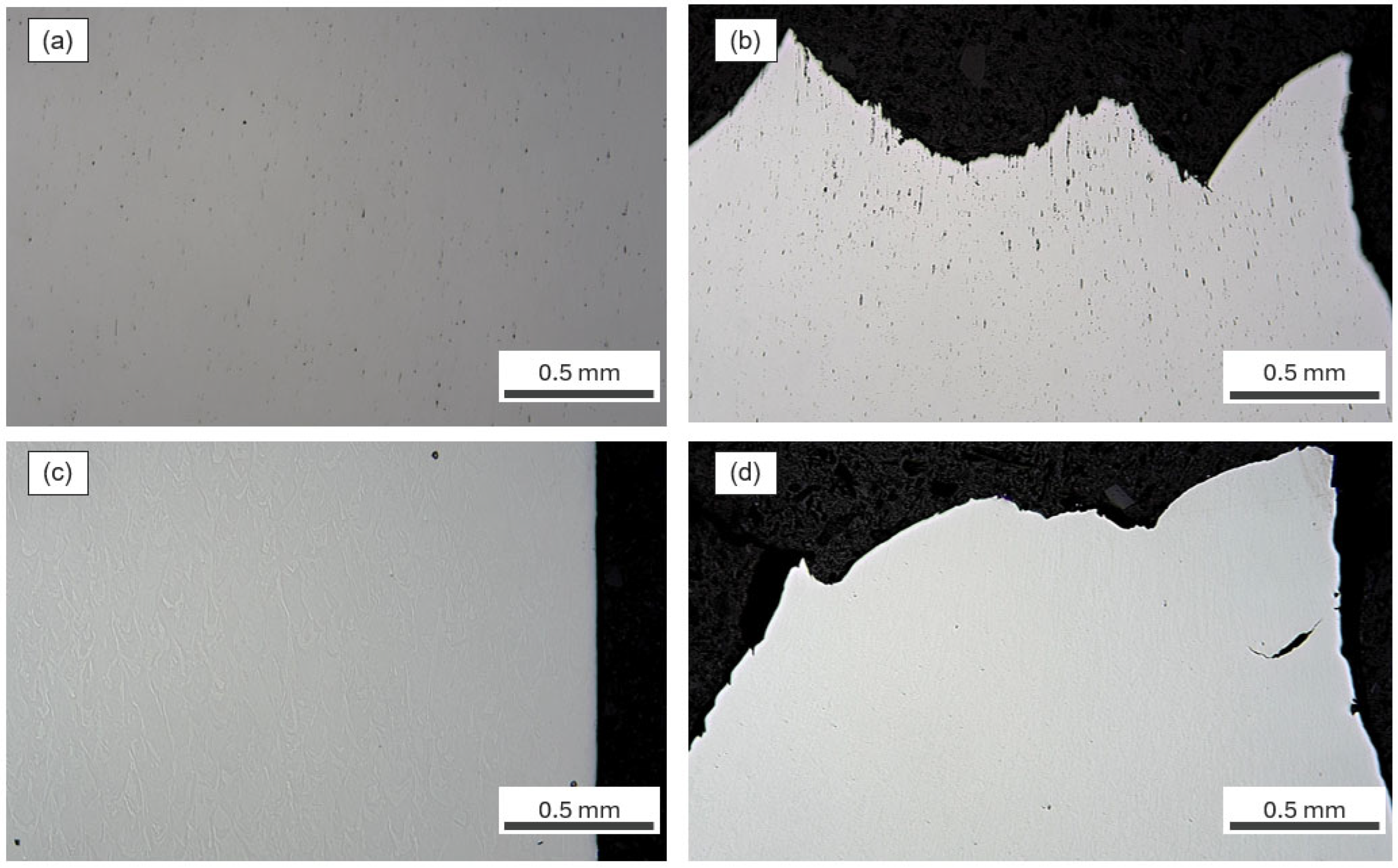
Microstructure analyses of CM (top) and AM (bottom) 316L tensile bars after failures that were subjected to 100% hydrogen for 24 weeks. (a) CM 316L stainless steel below the fracture surface of the EDS performed in Figure 10 and (b) at the fracture surface, full of MnS and other inclusions; (c) AM 316L stainless steel below the fracture surface with a few visible voids and (d) at the fracture surface with internal cracking present.
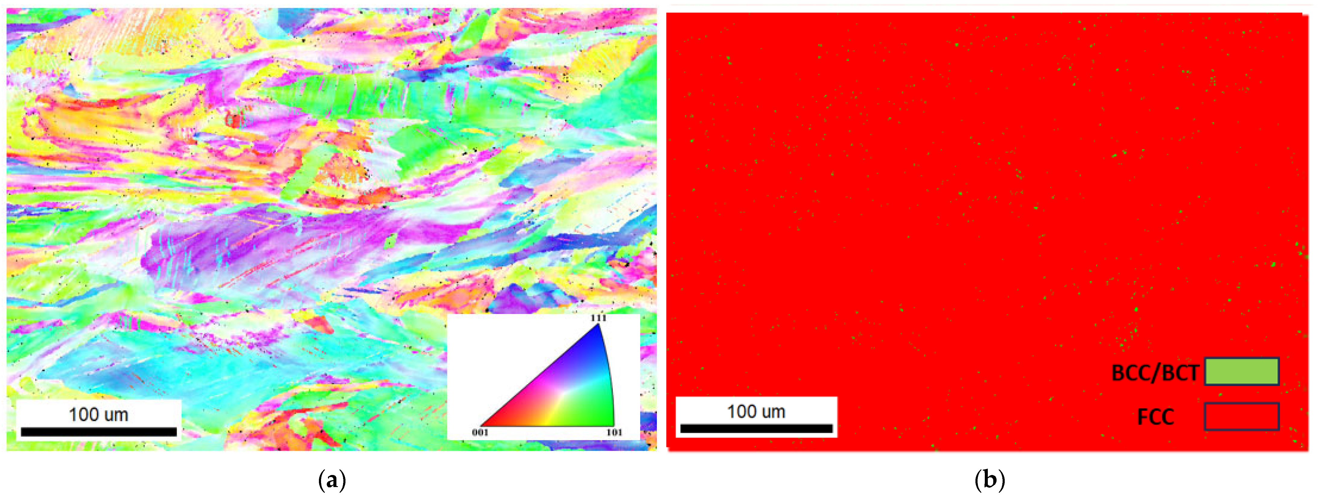
Hydrogen trapped in the voids of the AM samples soaked in 100% hydrogen were able to facilitate failure, likely from the HELP mechanism of HE. Voids have one of the highest trapping energies for hydrogen at around 40 J/mol, slightly less than most inclusions (30–80 J/mol), but allow for the rapid diffusion of hydrogen compared with other defect features [43]. These sites allow for quick hydrogen accumulation and create regions of localized plasticity, enhancing dislocation motion. This led to weak regions in the AM samples, despite the relatively low concentrations of hydrogen found [44]. Previous research suggested a self-consistent void-based hydrogen embrittlement (CVHE) model where hydrogen could take advantage of small voids to create brittle regions with micro-voids [45]. Once a large amount of stress is applied (i.e., tensile testing), the voids grow and become dominated by the HELP mechanism. Intrinsically, AM technology lends itself to creating small voids even with the best parameters and 99%+ density [46] and is thus susceptible to HE by these mechanisms in extreme hydrogen concentrations, as observed in this study. To confirm the presence, distribution, and size of the voids throughout the sample, X-ray microscopy (XRM) was performed. As shown in Figure 12, XRM revealed that 99.3% of the AM sample was solid and 0.7% was air by volume (compared with 100% of the CM samples). This 0.7% consisted of micro-voids distributed throughout the AM samples. The size of the voids was approximately 20 µm or less, which agrees with the theory of CVHE where many micro-voids act as sites to accelerate the embrittlement process [40]. These voids trap the hydrogen and likely facilitate the HELP failure at each void where hydrogen coalesces. This phenomenon can be observed in Figure 9f, where ductile regions can still be seen around the crack feature, indicating localized weakening due to hydrogen. With the applied stress, all areas with locally trapped hydrogen promoted martensitic transformation and led to uneven loading throughout the sample, resulting in the oval cross-section shown in Figure 8 d. The EBSD analysis of the AM 316L samples confirmed the presence of localized transformation around the voids, as seen in Figure 13. Mostly austenite was observed with interspersed pockets of transformed martensite, likely due to the presence of H, in the AM 316L samples. Only austenite was observed in the CM 316L samples.
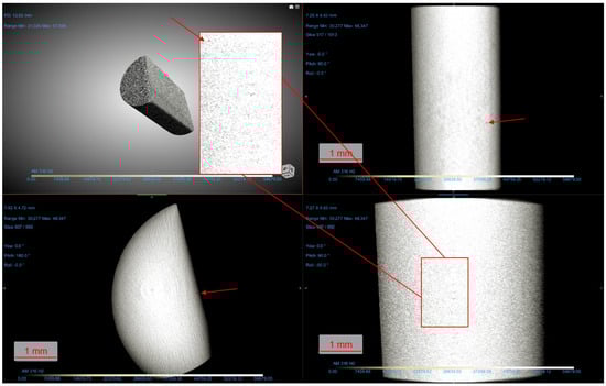
Figure 12.
XRM imaging of an AM 316L sample that was soaked in 100% hydrogen for 24 weeks. Micro-voids are highlighted in all three plane cut views along with a close-up of the XY plane projection compared with the 3D reconstruction (top left).
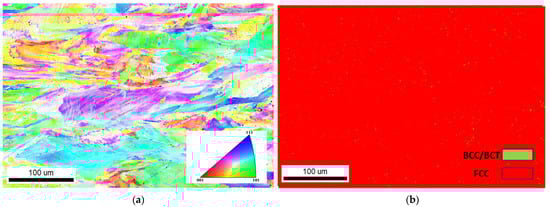
Figure 13.
EBSD imaging of an AM 316L sample soaked for 12 weeks in 100% hydrogen below the fracture surface with (a) an IPF map and (b) a phase map showing localized regions of martensitic transformation.
4. Conclusions
To investigate the impact of hydrogen on CM 316L and AM 316L stainless steel samples, we exposed the samples to low-pressure hydrogen conditions comparable to service conditions.
- CM 316L did not show any changes in hydrogen ppm in all conditions, but consistently showed a higher hydrogen content than AM 316L due to MnS inclusions.
- AM 316L showed no changes in 50% hydrogen, likely due to an extremely low dissociation rate and the shielding effect of the natural gas.
- AM 316L experienced HE in 100% hydrogen due to a significant number of micro-voids from the AM processing conditions.
- CM 316L showed no changes in mechanical properties, but AM 316L showed a reduction of 20% ductility and an increase of about 15% yield stress for the 100% hydrogen condition.
To mitigate this issue, post-processing techniques such as hot isostatic pressing or solution annealing may be necessary to reduce or eliminate these defects before AM 316L can be considered to be suitable for operation in pure-hydrogen service conditions. Further research is needed to explore effective methods for defect reduction and to ensure the safe application of additively manufactured metals in harsh environments. Future research should also consider performing tests in situ with hydrogen as well as analyzing the effect of build orientation on the degree of HE in AM samples.
Author Contributions
G.G.: Conceptualization, Methodology, Software, Validation, Formal Analysis, Investigation, Data Curation, and Writing—Original Draft; A.B.: Project Administration, Funding Acquisition, Methodology, and Resources. M.L.Y.: Writing—Review and Editing, Supervision, and Resources. All authors have read and agreed to the published version of the manuscript.
Funding
This research received no external funding.
Data Availability Statement
The dataset is available from the authors on request.
Acknowledgments
This work was performed in part at the University of North Texas’s Materials Research Facility, a shared research facility for multi-dimensional fabrication and characterization. The authors acknowledge the Advanced Materials and Manufacturing Processes Institute (AMMPI) at the University of North Texas for providing seed funding.
Conflicts of Interest
The authors declare no conflicts of interest.
Abbreviations
The following abbreviations are used in this manuscript:
| HE | Hydrogen Embrittlement |
| LBPF | Laser-Bed Powder Fusion |
| AM | Additive-Manufactured |
| CM | Conventionally Manufactured |
References
- Carey, J. The other benefit of electric vehicles. Proc. Natl. Acad. Sci. USA 2023, 120, e2220923120. [Google Scholar] [CrossRef]
- Drennen, T.E.; Erickson, J.D.; Chapman, D. Solar power and climate change policy in developing countries. Energy Policy 1996, 24, 9–16. [Google Scholar] [CrossRef]
- Siqueira, D.S.; de Almeida Meystre, J.; Hilário, M.Q.; Rocha, D.H.D.; Menon, G.J.; da Silva, R.J. Current perspectives on nuclear energy as a global climate change mitigation option. Mitig. Adapt. Strat. Glob. Change. 2019, 24, 749–777. [Google Scholar] [CrossRef]
- Susskind, L.; Chun, J.; Gant, A.; Hodgkins, C.; Cohen, J.; Lohmar, S. Sources of opposition to renewable energy projects in the United States. Energy Policy 2022, 165, 112922. [Google Scholar] [CrossRef]
- Baron, J.; Herzog, S. Public opinion on nuclear energy and nuclear weapons: The attitudinal nexus in the United States. Energy Res. Soc. Sci. 2020, 68, 101567. [Google Scholar] [CrossRef]
- Road map to a US hydrogen economy. Fuel Cells Bull. 2020, 2020, 12. [CrossRef]
- Ekhtiari, A.; Flynn, D.; Syron, E. Green Hydrogen Blends with Natural Gas and Its Impact on the Gas Network. Hydrogen 2022, 3, 402–417. [Google Scholar] [CrossRef]
- Raju, A.; Martinez-Morales, A. Hydrogen Blending Impacts Study; California Public Utilities Commission: Riverside, CA, USA, 2022. [Google Scholar]
- Kappes, M.A.; Perez, T.E. Blending hydrogen in existing natural gas pipelines: Integrity consequences from a fitness for service perspective. J. Pipeline Sci. Eng. 2023, 3, 100141. [Google Scholar] [CrossRef]
- Cristello, J.B.; Yang, J.M.; Hugo, R.; Lee, Y.; Park, S.S. Feasibility analysis of blending hydrogen into natural gas networks. Int. J. Hydrogen Energy 2023, 48, 17605–17629. [Google Scholar] [CrossRef]
- Alami, A.H.; Olabi, A.G.; Alashkar, A.; Alasad, S.; Aljaghoub, H.; Rezk, H.; Abdelkareem, M.A. Additive manufacturing in the aerospace and automotive industries: Recent trends and role in achieving sustainable development goals. Ain Shams Eng. J. 2023, 14, 102516. [Google Scholar] [CrossRef]
- Vendra, L. Metal additive manufacturing in the oil and gas industry. In Proceedings of the 2018 International Solid Freeform Fabrication Symposium, Austin, TX, USA, 13–15 August 2018. [Google Scholar]
- Bell, B.; Speese, D. Additive Manufacturing the Fisher Cavitrol Hex Trim—The Cool Parts Show; Technologies, Valves, Actuators & Regulators, 2023. Available online: https://www.emersonautomationexperts.com/2023/valves-actuators-regulators/additive-manufacturing-fisher-cavitrol-hex-trim-cool-parts-show/ (accessed on 16 May 2025).
- Hejazi, D.; Calka, A.; Dunne, D.; Pereloma, E. Effect of gaseous hydrogen charging on the tensile properties of standard and medium Mn X70 pipeline steels. Mater. Sci. Technol. 2016, 32, 675–683. [Google Scholar] [CrossRef]
- Nguyen, T.T.; Heo, H.M.; Park, J.; Nahm, S.H.; Beak, U.B. Stress concentration affecting hydrogen-assisted crack in API X70 pipeline base and weld steel under hydrogen/natural gas mixture. Eng. Fail. Anal. 2021, 122, 105242. [Google Scholar] [CrossRef]
- Martin, M.L.; Connolly, M.J.; DelRio, F.W.; Slifka, A.J. Hydrogen embrittlement in ferritic steels. Appl. Phys. Rev. 2020, 7, 041301. [Google Scholar] [CrossRef]
- Bhadeshia, H.K.D.H. Prevention of Hydrogen Embrittlement in Steels. ISIJ Int. 2016, 56, 24–36. [Google Scholar] [CrossRef]
- Michler, T.; Marchi, C.S.; Naumann, J.; Weber, S.; Martin, M. Hydrogen environment embrittlement of stable austenitic steels. Int. J. Hydrogen Energy 2012, 37, 16231–16246. [Google Scholar] [CrossRef]
- Lee, J.S.; Kim, S.R.; Shin, J.; Yun, K.S.; Kim, C.H.; Je, G.J.; Choi, H.I.; Chen, L. Development of a regulator for high-pressure hydrogen charging and storage system. Int. J. Air-Cond. Refrig. 2024, 32, 10. [Google Scholar] [CrossRef]
- Álvarez, G.; Harris, Z.; Wada, K.; Rodríguez, C.; Martínez-Pañeda, E. Hydrogen embrittlement susceptibility of additively manufactured 316L stainless steel: Influence of post-processing, printing direction, temperature and pre-straining. Addit. Manuf. 2023, 78, 103834. [Google Scholar] [CrossRef]
- Bertsch, K.M.; Nagao, A.; Rankouhi, B.; Kuehl, B.; Thoma, D.J. Hydrogen embrittlement of additively manufactured austenitic stainless steel 316 L. Corros. Sci. 2021, 192, 109790. [Google Scholar] [CrossRef]
- Yao, J.; Tan, Q.; Venezuela, J.; Atrens, A.; Zhang, M.-X. Recent research progress in hydrogen embrittlement of additively manufactured metals—A review. Curr. Opin. Solid. State Mater. Sci. 2023, 27, 101106. [Google Scholar] [CrossRef]
- Metalnikov, P.; Ben-Hamu, G.; Eliezer, D. Hydrogen Trapping in Laser Powder Bed Fusion 316L Stainless Steel. Metals 2022, 12, 1748. [Google Scholar] [CrossRef]
- Khedr, M.; Hamada, A.; Abd-Elaziem, W.; Jaskari, M.; Elsamanty, M.; Kömi, J.; Järvenpää, A. Effects of Wall Thickness Variation on Hydrogen Embrittlement Susceptibility of Additively Manufactured 316L Stainless Steel with Lattice Auxetic Structures. Materials 2023, 16, 2523. [Google Scholar] [CrossRef]
- Zhang, P.; Laleh, M.; Hughes, A.E.; Marceau, R.K.W.; Hilditch, T.; Tan, M.Y. A systematic study on the influence of electrochemical charging conditions on the hydrogen embrittlement behaviour of a pipeline steel. Int. J. Hydrogen Energy 2023, 48, 16501–16516. [Google Scholar] [CrossRef]
- Koren, E.; Hagen, C.M.H.; Wang, D.; Lu, X.; Johnsen, R.; Yamabe, J. Experimental comparison of gaseous and electrochemical hydrogen charging in X65 pipeline steel using the permeation technique. Corros. Sci. 2023, 215, 111025. [Google Scholar] [CrossRef]
- Yang, R.; Schell, C.A.; Rayasam, D.; Groth, K.M. Hydrogen impact on transmission pipeline risk: Probabilistic analysis of failure causes. Reliab. Eng. Syst. Saf. 2025, 257 Pt A, 110825. [Google Scholar] [CrossRef]
- Sofia, D.; Lotrecchiano, N.; Giuliano, A.; Barletta, D.; Poletto, M. Optimization of Number and Location of Sampling Points of an Air Quality Monitoring Network in an Urban Contest. Chem. Eng. Trans. 2019, 74, 277–282. [Google Scholar]
- Shim, D.S.; Lee, H.; Son, Y.; Oh, W.J. Effects of pre- and post-repair heat treatments on microstructure and tensile behaviors of 630 stainless steel repaired by metal additive manufacturing. J. Mater. Res. Technol. 2021, 13, 980–999. [Google Scholar] [CrossRef]
- Lynch, S. Hydrogen embrittlement phenomena and mechanisms. Corros. Rev. 2012, 30, 105–123. [Google Scholar] [CrossRef]
- Babakr, A.; Gamboa, G. Optimizing Additive Manufacturing in the Chemical Industry. Chemical Engineering, 15 March 2024. [Google Scholar]
- Emerson, P.R.M. MR95 Series Industrial Pressure Regulators; Emerson: St. Louis, MO, USA, 2022. [Google Scholar]
- ASTM E8/E8M-22; Test Methods for Tension Testing of Metallic Materials. ASTM International: West Conshohocken, PA, USA, 2022. [CrossRef]
- Hatano, M.; Fujinami, M.; Arai, K.; Fujii, H.; Nagumo, M. Hydrogen embrittlement of austenitic stainless steels revealed by deformation microstructures and strain-induced creation of vacancies. Acta Mater. 2014, 67, 342–353. [Google Scholar] [CrossRef]
- Gamboa, G.; Babakr, A.; Griffin, J.; Young, M. Susceptibility Study of Common Regulator Alloys to Hydrogen Embrittlement. In Proceedings of the AMPP Annual Conference, New Orleans, LA, USA, 3–7 March 2024; Volume 1149. [Google Scholar]
- Lee, J.-Y.; Lee, S.M. Hydrogen trapping phenomena in metals with B.C.C. and F.C.C. crystals structures by the desorption thermal analysis technique. Surf. Coat. Technol. 1986, 28, 301–314. [Google Scholar] [CrossRef]
- Bandyopadhyay, A.; Traxel, K.D.; Lang, M.; Juhasz, M.; Eliaz, N.; Bose, S. Alloy design via additive manufacturing: Advantages, challenges, applications and perspectives. Mater. Today 2022, 52, 207–224. [Google Scholar] [CrossRef]
- Norouzi, E.; Miresmaeili, R.; Shahverdi, H.R.; Askari-Paykani, M.; Vergani, L.M. Hydrogen embrittlement behavior in FeCCrNiBSi TRIP steel. J. Mater. Res. Technol. 2023, 23, 859–868. [Google Scholar] [CrossRef]
- Gamboa, G.; Babakr, A.; Young, M. Effect of Hydrogen-Blended Natural Gas on Additive Manufactured 316L Stainless Steel in Pressure Regulator Environments. In TMS Annual Meeting & Exhibition; Springer: Cham, Switzerland, 2025; pp. 200–210. [Google Scholar] [CrossRef]
- Claeys, L.; Deconinck, L.; Verbeken, K.; Depover, T. Effect of additive manufacturing and subsequent heat and/or surface treatment on the hydrogen embrittlement sensitivity of 316L austenitic stainless steel. Int. J. Hydrogen Energy 2023, 48, 36142–36157. [Google Scholar] [CrossRef]
- Hong, Y.; Zhou, C.; Wagner, S.; Schlabach, S.; Pundt, A.; Zhang, L.; Zheng, J. Strain-induced twins and martensite: Effects on hydrogen embrittlement of selective laser melted (SLM) 316 L stainless steel. Corros. Sci. 2022, 208, 110669. [Google Scholar] [CrossRef]
- Liu, C.; Yang, H.; Wang, C.; Zhang, H.; Ding, R.; Ai, L.; Fan, X.; Zhang, R.; Xu, X.; Ning, Y.; et al. Effects of CH4 and CO on hydrogen embrittlement susceptibility of X80 pipeline steel in hydrogen blended natural gas. Int. J. Hydrogen Energy 2023, 48, 27766–27777. [Google Scholar] [CrossRef]
- Chen, Y.-S.; Huang, C.; Liu, P.-Y.; Yen, H.-W.; Niu, R.; Burr, P.; Moore, K.L.; Martínez-Pañeda, E.; Atrens, A.; Cairney, J.M. Hydrogen trapping and embrittlement in metals—A review. Int. J. Hydrogen Energy 2025, 136, 789–821. [Google Scholar] [CrossRef]
- Lynch, S.P. Hydrogen embrittlement (HE) phenomena and mechanisms. In Stress Corrosion Cracking; Elsevier: Amsterdam, The Netherlands, 2011; pp. 90–130. [Google Scholar] [CrossRef]
- Yu, H.; He, J.; Morin, D.D.; Ortiz, M.; Zhang, Z. A self-consistent void-based rationale for hydrogen embrittlement. Scr. Mater. 2025, 255, 116403. [Google Scholar] [CrossRef]
- Yusuf, S.M.; Gao, N. Influence of energy density on metallurgy and properties in metal additive manufacturing. Mater. Sci. Technol. 2017, 33, 1269–1289. [Google Scholar] [CrossRef]


Disclaimer/Publisher’s Note: The statements, opinions and data contained in all publications are solely those of the individual author(s) and contributor(s) and not of MDPI and/or the editor(s). MDPI and/or the editor(s) disclaim responsibility for any injury to people or property resulting from any ideas, methods, instructions or products referred to in the content. |
© 2025 by the authors. Licensee MDPI, Basel, Switzerland. This article is an open access article distributed under the terms and conditions of the Creative Commons Attribution (CC BY) license (https://creativecommons.org/licenses/by/4.0/).