
A Comparative Study on Corrosion Fatigue Susceptibility and Microstructural Effects in 6061-T6 and 6082-T6 Aluminum Alloys

 , , and
Abstract

1. Introduction
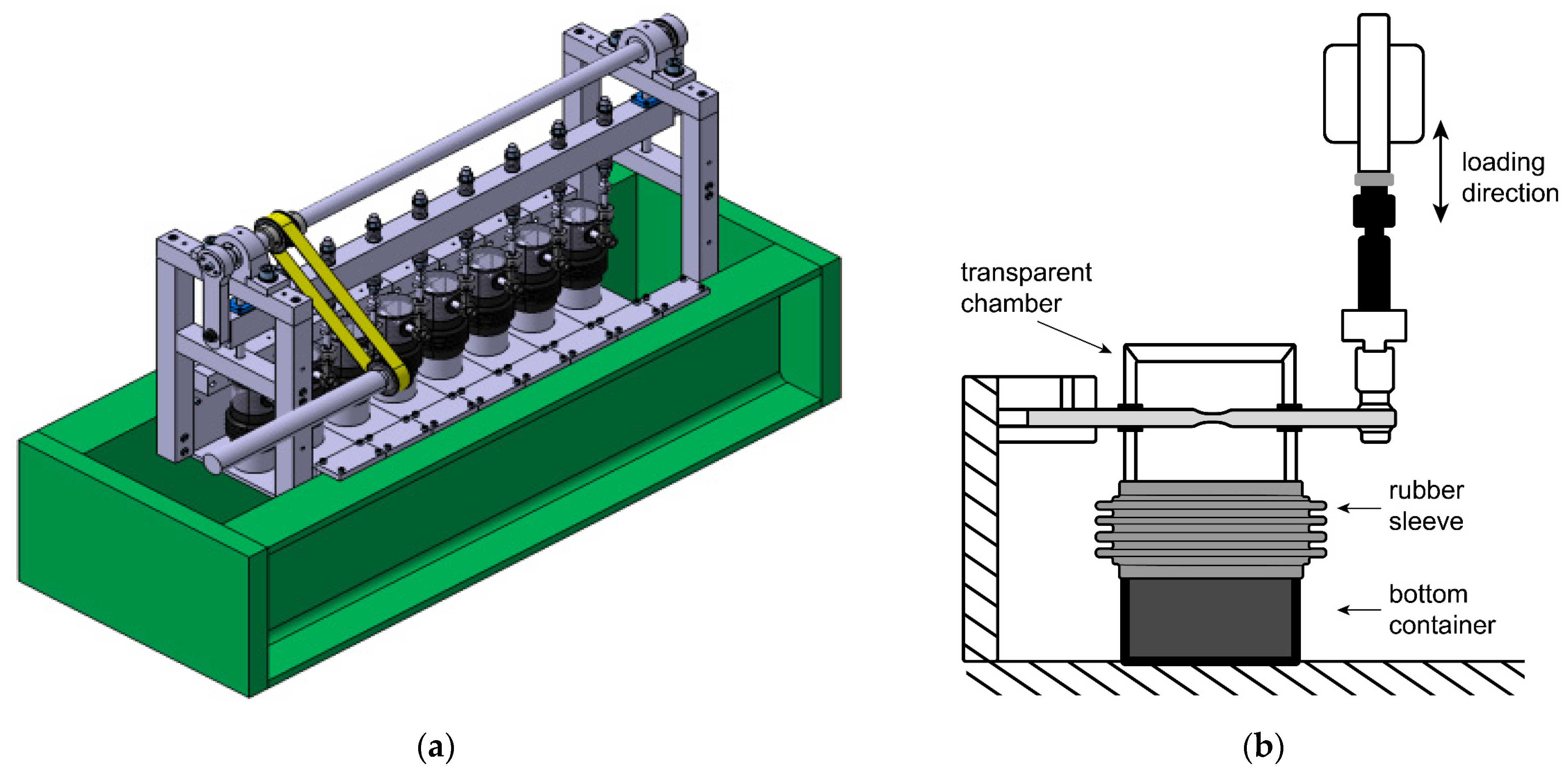
2. Materials and Methods
3. Results
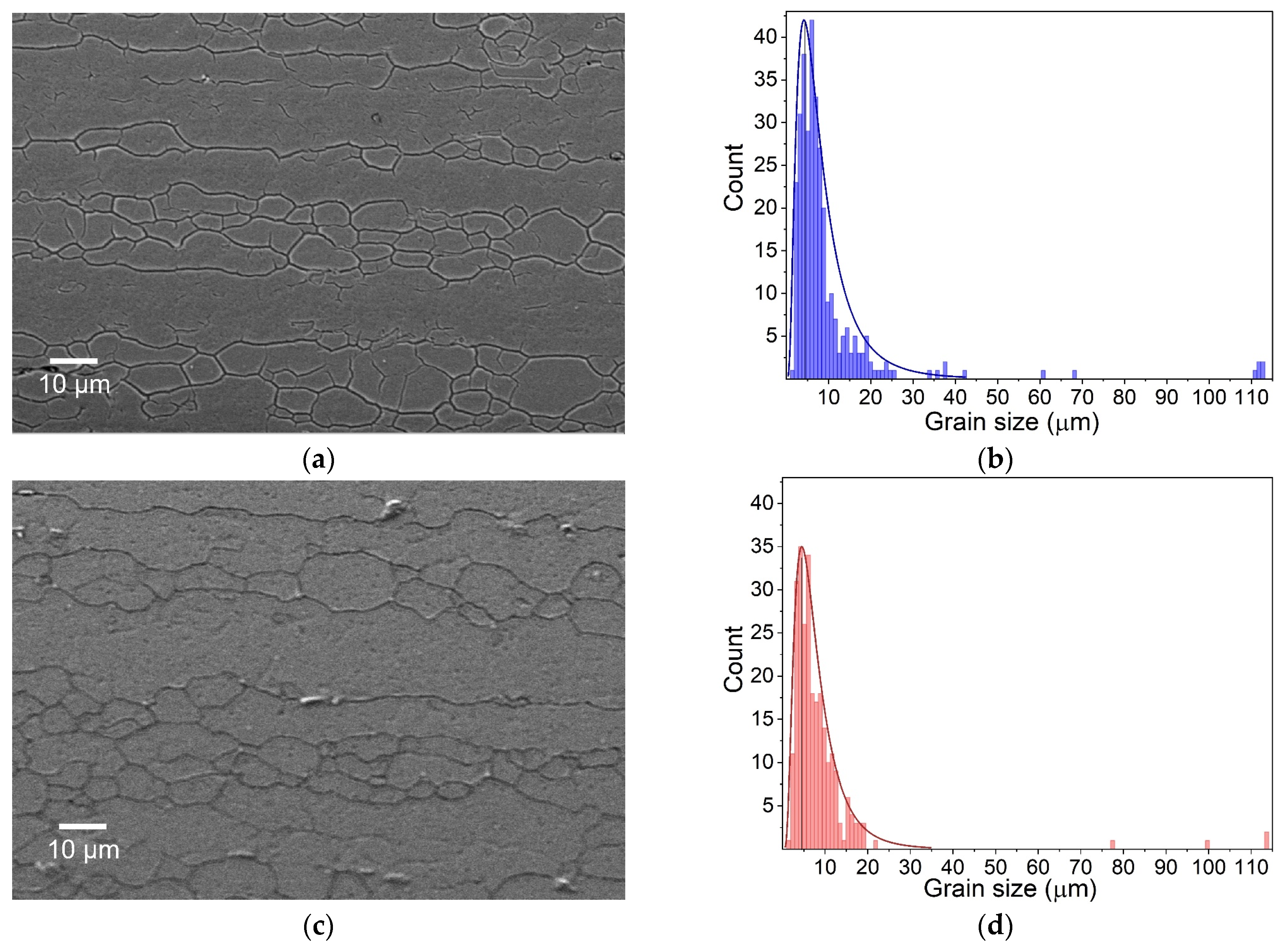
3.1. Microstructure
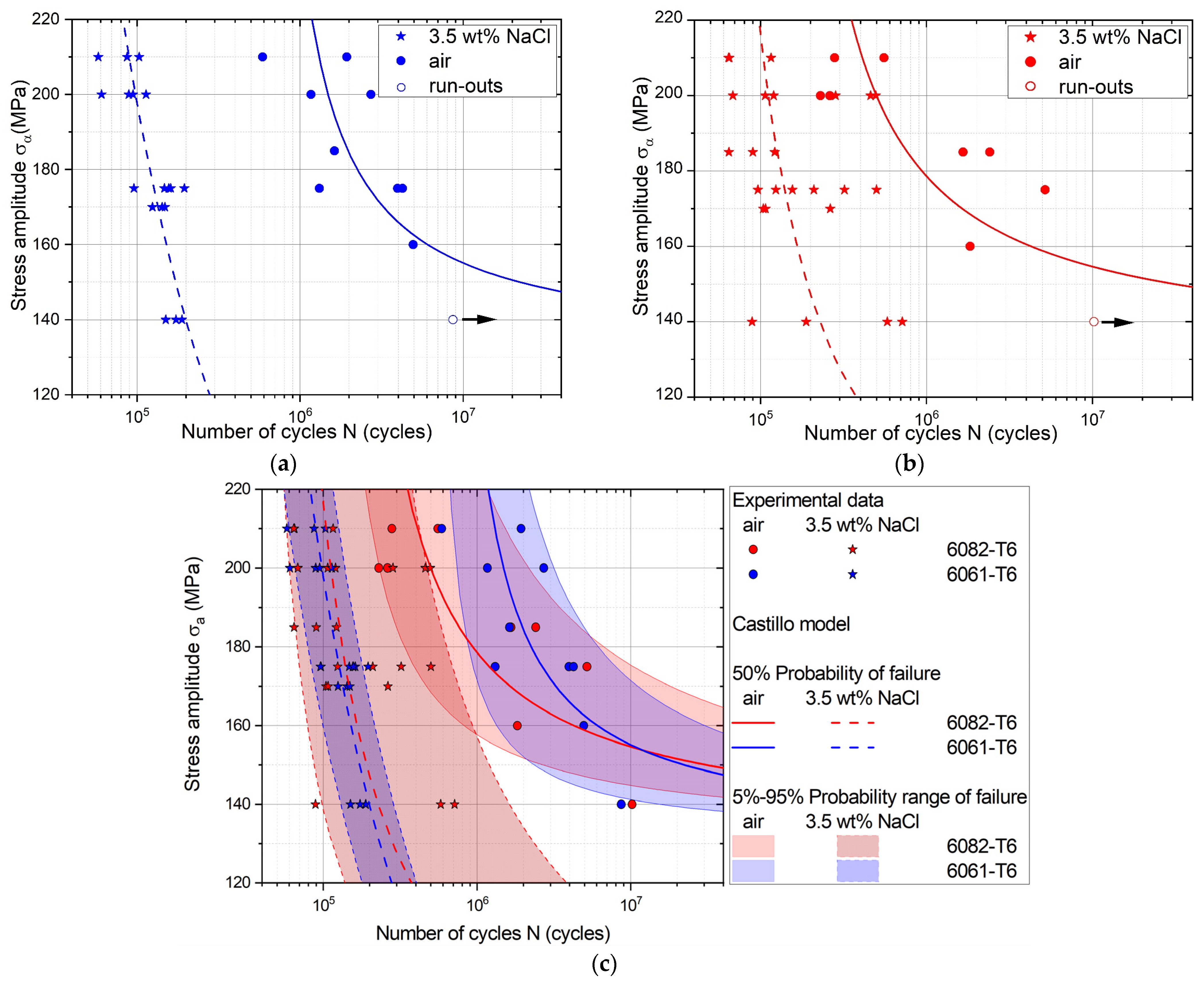
3.2. Corrosion Fatigue (S-N) Behavior
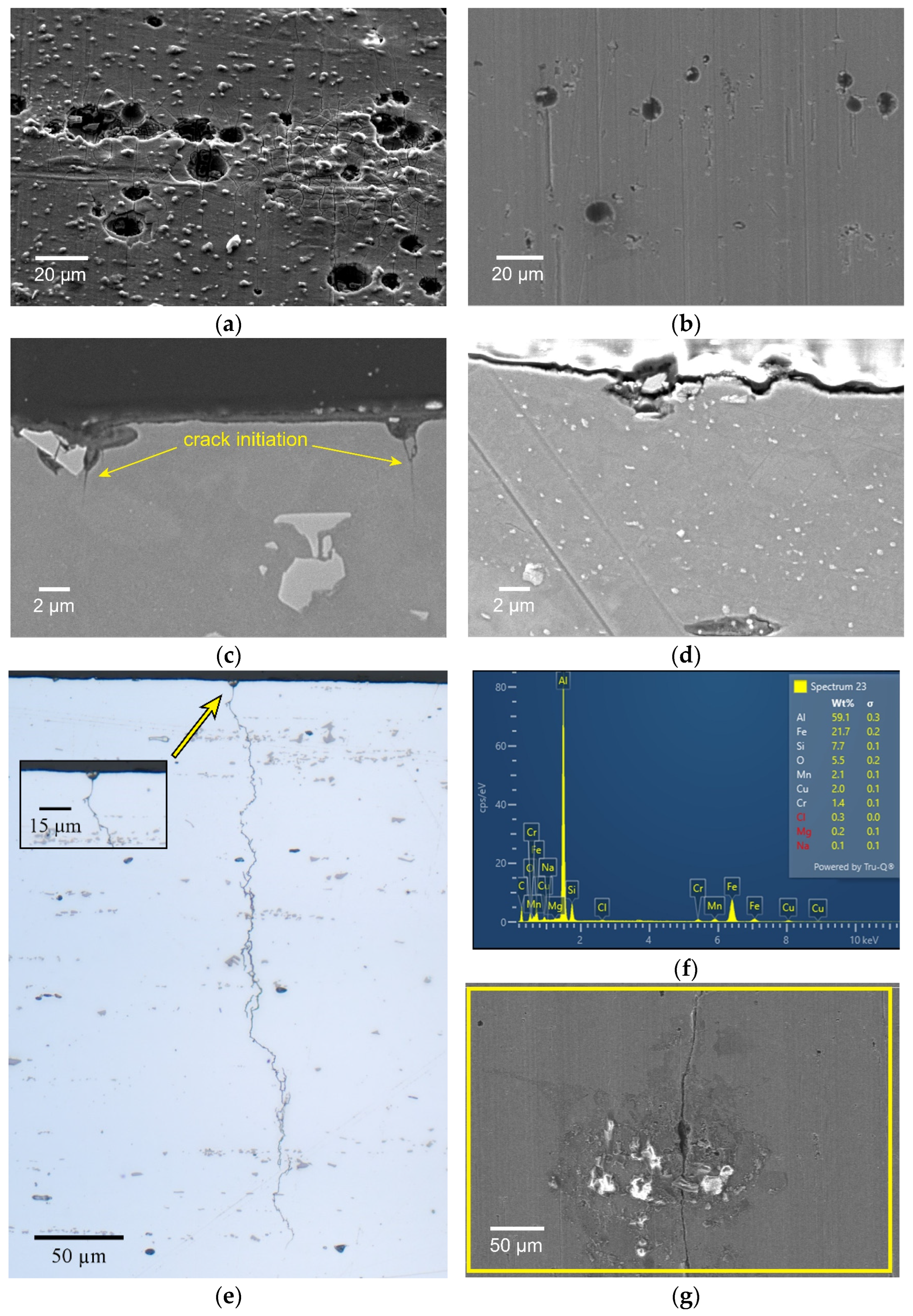
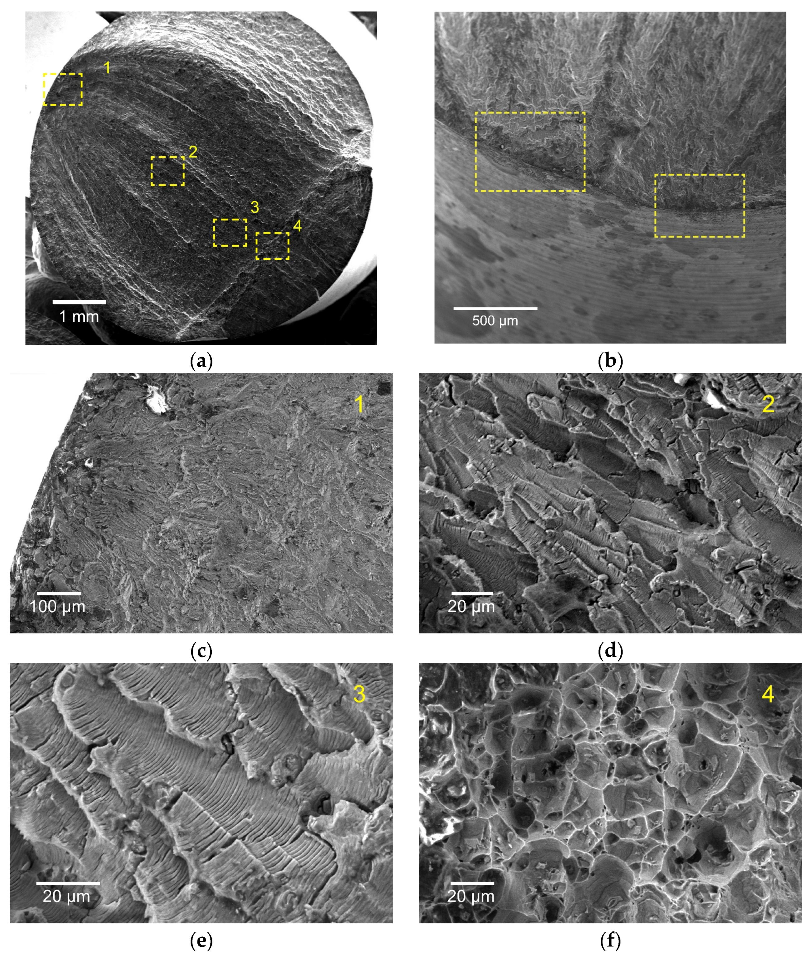
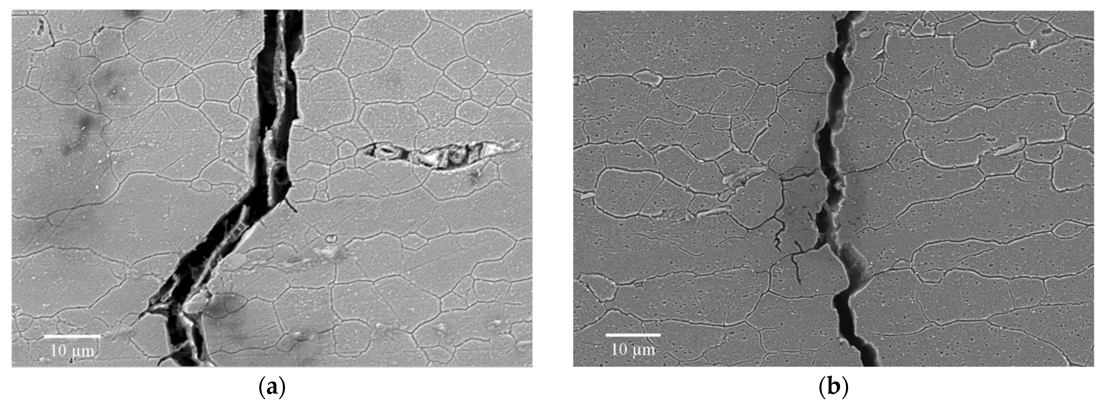
3.3. Pitting Corrosion and Crack Propagation Path
3.4. Effect of Other Variables on Corrosion Fatigue
4. Discussion
5. Conclusions
Author Contributions
Funding
Data Availability Statement
Acknowledgments
Conflicts of Interest
References
- Kumar, A.; Maithani, R.; Kumar, A.; Kumar, D.; Sharma, S. An All-Aluminium Vehicle’s Design and Feasibility Analysis. Mater. Today Proc. 2022, 64, 1244–1249. [Google Scholar] [CrossRef]
- Pian, W.; Zhou, Y.; Xiao, T. A Review of the Feasibility of Aluminum Alloys, Carbon Fiber Composites and Glass Fiber Composites for Vehicle Weight Reduction in the Automotive Industry. J. Phys. Conf. Ser. 2023, 2608, 012005. [Google Scholar] [CrossRef]
- Bartawi, E.H.; Mishin, O.V.; Shaban, G.; Grumsen, F.; Nordlien, J.H.; Ambat, R. The Effect of Trace Level Copper Content on Intergranular Corrosion of Extruded AA6082-T6 Alloys. Mater. Chem. Phys. 2023, 309, 128303. [Google Scholar] [CrossRef]
- Szklarska-Smialowska, Z. Pitting Corrosion of Aluminum. Corros. Sci. 1999, 41, 1743–1767. [Google Scholar] [CrossRef]
- Park, J.O.; Paik, C.H.; Huang, Y.H.; Alkire, R.C. Influence of Fe-Rich Intermetallic Inclusions on Pit Initiation on Aluminum Alloys in Aerated NaCl. J. Electrochem. Soc. 1999, 146, 517. [Google Scholar] [CrossRef]
- Birbilis, N.; Cavanaugh, M.K.; Buchheit, R.G. Electrochemical Behavior and Localized Corrosion Associated with Al7Cu2Fe Particles in Aluminum Alloy 7075-T651. Corros. Sci. 2006, 48, 4202–4215. [Google Scholar] [CrossRef]
- Kairy, S.K.; Rometsch, P.A.; Davies, C.H.J.; Birbilis, N. On the Intergranular Corrosion and Hardness Evolution of 6xxx Series Al Alloys as a Function of Si:Mg Ratio, Cu Content, and Aging Condition. Corrosion 2017, 73, 1280–1295. [Google Scholar] [CrossRef]
- Svenningsen, G.; Larsen, M.H.; Walmsley, J.C.; Nordlien, J.H.; Nisancioglu, K. Effect of Artificial Aging on Intergranular Corrosion of Extruded AlMgSi Alloy with Small Cu Content. Corros. Sci. 2006, 48, 1528–1543. [Google Scholar] [CrossRef]
- Zou, Y.; Liu, Q.; Jia, Z.; Xing, Y.; Ding, L.; Wang, X. The Intergranular Corrosion Behavior of 6000-Series Alloys with Different Mg/Si and Cu Content. Appl. Surf. Sci. 2017, 405, 489–496. [Google Scholar] [CrossRef]
- Nguyen, N.; Li, P. Fatigue Behaviour of AA6061-T6 Alloys in the Corrosive Environment. MATEC Web Conf. 2018, 165, 03015. [Google Scholar] [CrossRef]
- Chanyathunyaroj, K.; Phetchcrai, S.; Laungsopapun, G.; Rengsomboon, A. Fatigue Characteristics of 6061 Aluminum Alloy Subject to 3.5% NaCl Environment. Int. J. Fatigue 2020, 133, 105420. [Google Scholar] [CrossRef]
- Bland, L.G.; Locke, J.S. Chemical and Electrochemical Conditions within Stress Corrosion and Corrosion Fatigue Cracks. npj Mater. Degrad. 2017, 1, 12. [Google Scholar] [CrossRef]
- EN ISO 11782-1:1998; Corrosion of Metals and Alloys—Corrosion Fatigue Testing—Part 1: Cycles to Failure Testing. European Committee for Standardization (CEN): Brussels, Belgium, 1998.
- ASTM B117-19; Standard Practice for Operating Salt Spray (Fog) Apparatus. ASTM International: West Conshohocken, PA, USA, 2019.
- Papageorge, W.; Janas, G.; Beach, E. Development of a Versatile Two-Step Etchant to Reveal Grain Boundaries in Multiple Aluminum Alloys. Metallogr. Microstruct. Anal. 2023, 12, 865–871. [Google Scholar] [CrossRef]
- Fernández-Canteli, A.; Przybilla, C.; Nogal, M.; López Aenlle, M.; Castillo, E. ProFatigue: A Software Program for Probabilistic Assessment of Experimental Fatigue Data Sets. Procedia Eng. 2014, 74, 236–241. [Google Scholar] [CrossRef]
- Lynch, S.P. Mechanisms and Kinetics of Environmentally Assisted Cracking: Current Status, Issues, and Suggestions for Further Work. Met. Mater. Trans. A 2013, 44, 1209–1229. [Google Scholar] [CrossRef]
- Lin, C.-K.; Yang, S.-T. Corrosion Fatigue Behavior of 7050 Aluminum Alloys in Different Tempers. Eng. Fract. Mech. 1998, 59, 779–795. [Google Scholar] [CrossRef]
- Kakinuma, H.; Muto, I.; Oya, Y.; Momii, T.; Jin, Y.; Sugawara, Y.; Hara, N. Change in Oxygen Reduction Reactivity of Intermetallics: A Mechanism of the Difference in Trenching around Al–Fe and Al–Fe–Si Particles on AA1050 in NaCl. J. Electrochem. Soc. 2023, 170, 021503. [Google Scholar] [CrossRef]
- L’Haridon-Quaireau, S.; Laot, M.; Colas, K.; Kapusta, B.; Delpech, S.; Gosset, D. Effects of Temperature and pH on Uniform and Pitting Corrosion of Aluminium Alloy 6061-T6 and Characterisation of the Hydroxide Layers. J. Alloys Compd. 2020, 833, 155146. [Google Scholar] [CrossRef]
- Ikeuba, A.I.; Njoku, C.N.; Ekerenam, O.O.; Njoku, D.I.; Udoh, I.I.; Daniel, E.F.; Uzoma, P.C.; Etim, I.N.; Okonkwo, B.O. A Review of the Electrochemical and Galvanic Corrosion Behavior of Important Intermetallic Compounds in the Context of Aluminum Alloys. RSC Adv. 2024, 14, 31921–31953. [Google Scholar] [CrossRef]
- Shen, L.; Chen, H.; Xu, L.-D.; Che, X.-L.; Chen, Y. Stress Corrosion Cracking and Corrosion Fatigue Cracking Behavior of A7N01P-T4 Aluminum Alloy. Mater. Corros. 2018, 69, 207–214. [Google Scholar] [CrossRef]
- Ringdalen, I.G.; Jensen, I.J.T.; Marioara, C.D.; Friis, J. The Role of Grain Boundary Precipitates during Intergranular Fracture in 6xxx Series Aluminium Alloys. Metals 2021, 11, 894. [Google Scholar] [CrossRef]
- Scala, A.; Squillace, A.; Monetta, T.; Mitton, D.B.; Larson, D.; Bellucci, F. Corrosion Fatigue on 2024T3 and 6056T4 Aluminum Alloys. Surf. Interface Anal. 2010, 42, 194–198. [Google Scholar] [CrossRef]
- Menan, F.; Henaff, G. Influence of Frequency and Exposure to a Saline Solution on the Corrosion Fatigue Crack Growth Behavior of the Aluminum Alloy 2024. Int. J. Fatigue 2009, 31, 1684–1695. [Google Scholar] [CrossRef]
- Huang, I.-W.; Hurley, B.L.; Yang, F.; Buchheit, R.G. Dependence on Temperature, pH, and Cl− in the Uniform Corrosion of Aluminum Alloys 2024-T3, 6061-T6, and 7075-T6. Electrochim. Acta 2016, 199, 242–253. [Google Scholar] [CrossRef]


| Alloy | Alloying Elements, wt% | ||||||||
|---|---|---|---|---|---|---|---|---|---|
| Si | Mg | Fe | Cu | Mn | Cr | Zn | Ti | Others | |
| 6061-T6 | 0.54 | 1.02 | 0.27 | 0.35 | 0.12 | 0.33 | 0.04 | 0.02 | 0.03 |
| 6082-T6 | 0.87 | 0.96 | 0.16 | 0.04 | 0.49 | 0.06 | 0.03 | 0.01 | 0.08 |
| Alloy | Specification | Actual Value | ||||
|---|---|---|---|---|---|---|
| Rm, MPa | Rp0.2, MPa | A, % | Rm, MPa | Rp0.2, MPa | A, % | |
| 6061-T6 | 290–364 | 240–348 | 10–12 | 374 | 356 | 11 |
| 6082-T6 | 310–374 | 255–330 | 10–15 | 380 | 345 | 14 |
Disclaimer/Publisher’s Note: The statements, opinions and data contained in all publications are solely those of the individual author(s) and contributor(s) and not of MDPI and/or the editor(s). MDPI and/or the editor(s) disclaim responsibility for any injury to people or property resulting from any ideas, methods, instructions or products referred to in the content. |
© 2025 by the authors. Licensee MDPI, Basel, Switzerland. This article is an open access article distributed under the terms and conditions of the Creative Commons Attribution (CC BY) license (https://creativecommons.org/licenses/by/4.0/).
Share and Cite
Avramenko, T.; Michel, S.; Stutz, A.; Kollender, J.; Burda, I.; Hans, U.; Affolter, C.; Terrasi, G.P. A Comparative Study on Corrosion Fatigue Susceptibility and Microstructural Effects in 6061-T6 and 6082-T6 Aluminum Alloys. Metals 2025, 15, 653. https://doi.org/10.3390/met15060653
Avramenko T, Michel S, Stutz A, Kollender J, Burda I, Hans U, Affolter C, Terrasi GP. A Comparative Study on Corrosion Fatigue Susceptibility and Microstructural Effects in 6061-T6 and 6082-T6 Aluminum Alloys. Metals. 2025; 15(6):653. https://doi.org/10.3390/met15060653
Chicago/Turabian StyleAvramenko, Tetiana, Silvain Michel, Alex Stutz, Jan Kollender, Iurii Burda, Ulrik Hans, Christian Affolter, and Giovanni Pietro Terrasi. 2025. "A Comparative Study on Corrosion Fatigue Susceptibility and Microstructural Effects in 6061-T6 and 6082-T6 Aluminum Alloys" Metals 15, no. 6: 653. https://doi.org/10.3390/met15060653
APA StyleAvramenko, T., Michel, S., Stutz, A., Kollender, J., Burda, I., Hans, U., Affolter, C., & Terrasi, G. P. (2025). A Comparative Study on Corrosion Fatigue Susceptibility and Microstructural Effects in 6061-T6 and 6082-T6 Aluminum Alloys. Metals, 15(6), 653. https://doi.org/10.3390/met15060653