Article

Tribological Property of AlCoCrFeNi Coating Electrospark-Deposited on H13 Steel

1
School of Environment and Safety Engineering, North University China, Taiyuan 030051, China
2
China Rongtong Resources Development Group Co., Ltd., Beijing 100017, China
3
School of Equipment Engineering, Shenyang Ligong University, Shenyang 110159, China
4
China Rongtong Resources Development Company 3305 Factory, Dunhua 133700, China
*
Authors to whom correspondence should be addressed.
Metals 2025, 15(6), 649; https://doi.org/10.3390/met15060649
Submission received: 26 April 2025 / Revised: 1 June 2025 / Accepted: 6 June 2025 / Published: 10 June 2025
(This article belongs to the Special Issue Advances in the Design and Behavior Analysis of High-Strength Steels)

Abstract

AlCoCrFeNi coatings were electrospark-deposited (ESD) on H13 steel substrates, and their nano-mechanical and tribological properties under a load of 2 N, 4 N, 6 N, 8 N, and 10 N were investigated by utilizing a nanoindentation instrument and a reciprocating friction and wear tester, respectively. The morphologies, composition, and phase structure of the as-deposited and worn AlCoCrFeNi coating were characterized using SEM (Scanning electron Microscope), EDS (Energy dispersive spectrometer), and XRD (X-Ray Diffraction). The results showed that the as-deposited AlCoCrFeNi coating with a nanocrystalline microstructure mainly consists of a BCC and B2 phase structure, and a gradient transition of elements between the coating and the substrate ensures an excellent bond between the coating and the substrate. The hardness of the AlCoCrFeNi coating exhibits an 8% increase, while its elastic modulus is reduced by 16% compared to the H13 steel. The AlCoCrFeNi coating remarkably increased the tribological property of the H13 steel under various loads, and its wear mechanism belongs to micro-cutting abrasive wear whilst that of the H13 steel can be characterized as severe adhesive wear. The friction coefficient and weight loss of the AlCoCrFeNi coating decrease with increasing load, both following a linear relationship with respect to the applied load. As the load intensifies, the work hardening sensitivity and oxidation degree on the worn surface of the coating are significantly enhanced, which collectively contributes to the improved tribological performance of the AlCoCrFeNi coating.

1. Introduction

H13 steel is widely used in industry for the manufacture of molds, cutting tools, and heat treatment equipment due to its good hardenability, strong toughness, and resistance to thermal cracking, making it ideal for use in high-temperature environments [1,2,3,4]. However, the lack of wear resistance of H13 steel reduces the service life of molds after hot working, and thus surface techniques are often required to increase its surface tribological performance in order to extend the service life of molds [5].
High-entropy alloys (HEAs) represent a novel category of metallic materials, distinguished by the homogeneous distribution of multiple principal elements within the alloys. This unique combination of elements imparts a high degree of complexity to the microstructure of the alloys, which is manifested in the coexistence of fine grain structures, amorphous phases, and even nanoscale microscopic features [6,7]. The exceptional properties exhibited by HEAs, including high strength, high toughness, and excellent wear resistance, are primarily attributable to the inherent properties of their complex microstructures, thus allowing HEAs to provide potential advantages for the preparation of coatings on steel surfaces to improve wear resistance for a wide range of applications [8,9,10]. AlCoCrFeNi is one of the most studied HEAs due to its adjustable dual-phase (BCC/B2) structure, which synergistically enhances hardness and oxidation resistance compared to single-phase HEAs.
HEA coatings can maintain many performance advantages of HEAs for practical applications without requiring a large amount of manufacture cost. Recent studies on AlCoCrFeNi coatings prepared by laser cladding [11,12], thermal spraying [13,14,15], and magnetron sputtering [16] have demonstrated their exceptional wear resistance. For instance, Li et al. [17] reported that laser-cladded AlCoCrFeNi coatings significantly improved the wear resistance of H13 steel. Compared to these methods, electrospark deposition (ESD) offers distinct characteristics, including finer grain structure (105–106 K/s cooling rate), minimal substrate heat input, and cost-effectiveness [18,19,20,21]. These advantages make ESD particularly suitable for the localized surface enhancement of industrial components such as molds and cutting tools [22,23]. In this study, AlCoCrFeNi coatings were prepared on H13 steel by the ESD technique to obtain better wear resistance in comparison to the substrate. The properties of AlCoCrFeNi coatings under different loads were investigated in detail.

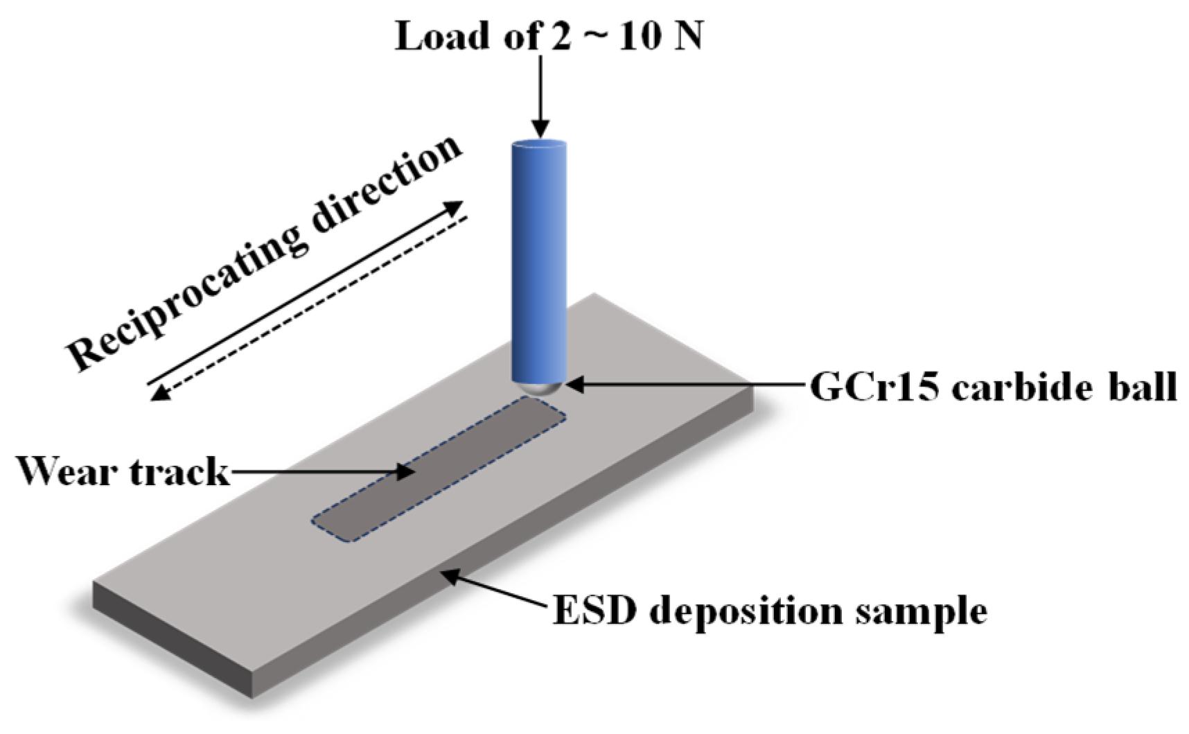
2. Materials and Experimental Methods

2.1. Materials

The substrate material for this experiment is H13 steel, and its main chemical composition is shown in Table 1. The samples were wire-electrode-cut into a cuboid shape with dimensions of 20 mm × 10 mm × 2 mm, then polished using 240#, 800#, 1500#, and 2000# sandpapers in turn, and after that ultrasonically cleaned with alcohol for 10 min and immediately dried with a high-pressure air gun.
A high-vacuum arc melting system was used to melt Al, Co, Cr, Fe, and Ni powders with an equal atomic amount of each component, and the melted AlCoCrFeNi HEA was processed into a cylindrical electrode with a size of Φ5 mm × 36 mm by using an SYJ-400 automatic precision cutter (Shanghai Hengyi Precision Instruments, Shanghai, China). The ESD process was carried out by using the DJ-2000 adjustable power metal surface repair machine (Shanghai Kangbei Mechanical and Electrical Equipment Co., Ltd., Jiading District, Shanghai, China) to deposit AlCoCrFeNi coatings on the H13 steel under argon protection. The pre-optimized parameters of the ESD process are shown in Table 2. For convenience, the H13 steel sample with an electrospark-deposited AlCoCrFeNi coating is denoted as AlCoCrFeNi coating.

2.2. Characterization of AlCoCrFeNi Coatings

The morphologies of the worn surface were observed using a Carl Zeiss Gemini 360 scanning electron microscope (SEM) made in Carl Zeiss AG, Oberkochen, Germany, and the chemical composition was analyzed using an energy dispersive spectrometer (EDS) attached to the SEM.
A Bruker D8 DISCOVER X-ray diffractometer (XRD, Bruker Corporation, Karlsruhe, Germany) was utilized to obtain the phase structure of the AlCoCrFeNi coating, and the settings are as follows: Cu target, a tube voltage of 40 kV, a tube current of 40 mA, a diffraction angle ranging from 10° to 120°, and a scanning step of 10°/min.
The hardness and modulus of the H13 steel and AlCoCrFeNi coating were measured using a nanoindentation instrument (G200, Instron Corporation, Innsworth, UK) equipped with a Berkovich diamond indenter. The instrument’s displacement resolution was set to 0.01–0.1 nm and its load resolution to 1 nN, thereby ensuring the acquisition of highly precise data. The Oliver–Pharr model was employed to facilitate the direct reading of the data from a computer. In the course of the measurement, 10 points were selected uniformly in the middle of the cross-section of the AlCoCrFeNi coating. The average maximum indentation depth was measured at 300 nm during the test, and the data between 100 nm and 200 nm indentation depths were selected as the results of the test. The maximum, minimum, and anomalies from the 10 data points were removed, and the final 5 data points were selected as the tested values for analysis. The microhardness of the worn surface of the AlCoCrFeNi coating was obtained by using an ultra-micro load microhardness tester (FUTURE–TECH CORP FM–300, Future-Tech Corporation, Jiangsu Province, Suzhou City, China) under a load of 10 g for 10 s. Five fields of view were selected to test the microhardness on the worn surface of the coating, and the average of the five tested data points was taken as the value of the microhardness of the sample.
The tribological property of the samples was tested using a high-speed reciprocating friction and wear tester (HSR–2M) produced by Lanzhou Zhongke Kaihua Science and Technology Development Corporation (Lanzhou City, Gansu Province, China). Figure 1 shows the schematic of the device used for the reciprocating friction and wear test. As shown in Figure 1, the counterpart used was a GCr15 steel ball with a diameter of 6 mm, the ambient temperature was maintained at room temperature, the sliding speed (number of reciprocations) was 300 t/min, the applied load was 2 N, 4 N, 6 N, 8 N, and 10 N, the length of reciprocating interval was 5 mm, and the total time of rubbing was 20 min for every sample. The GCr15 steel ball has a hardness of 800 HV and an elastic modulus of 210 GPa. The friction coefficient can be recorded in real time by the tribometer, and the weight loss of the sample was obtained by using a balance (0.01 mg precision; Sartorius BP211D, Sartorius AG, Göttingen, Germany). All of the data were the average results of three tests to ensure the stability and repeatability of the test.

3. Results

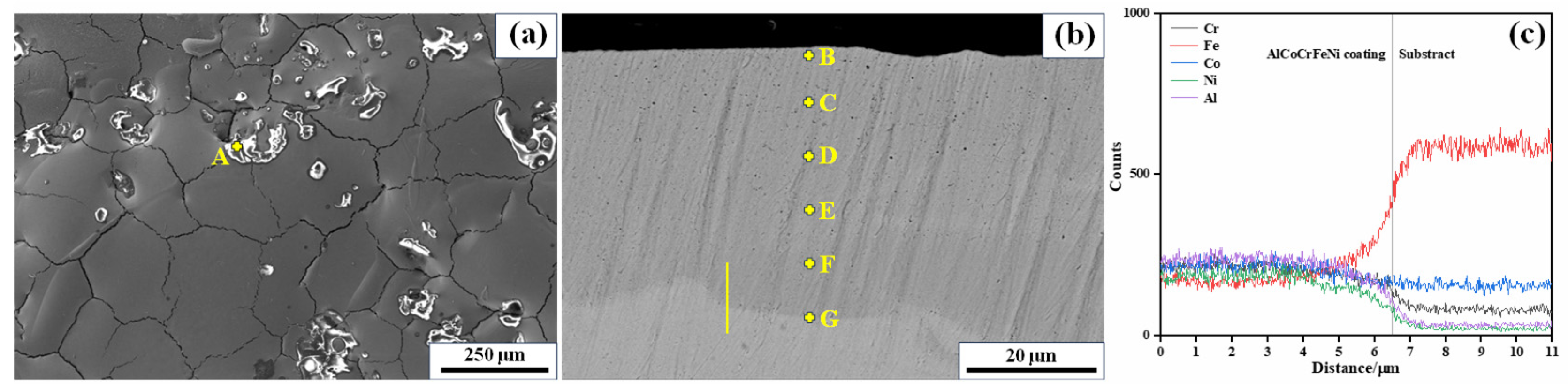
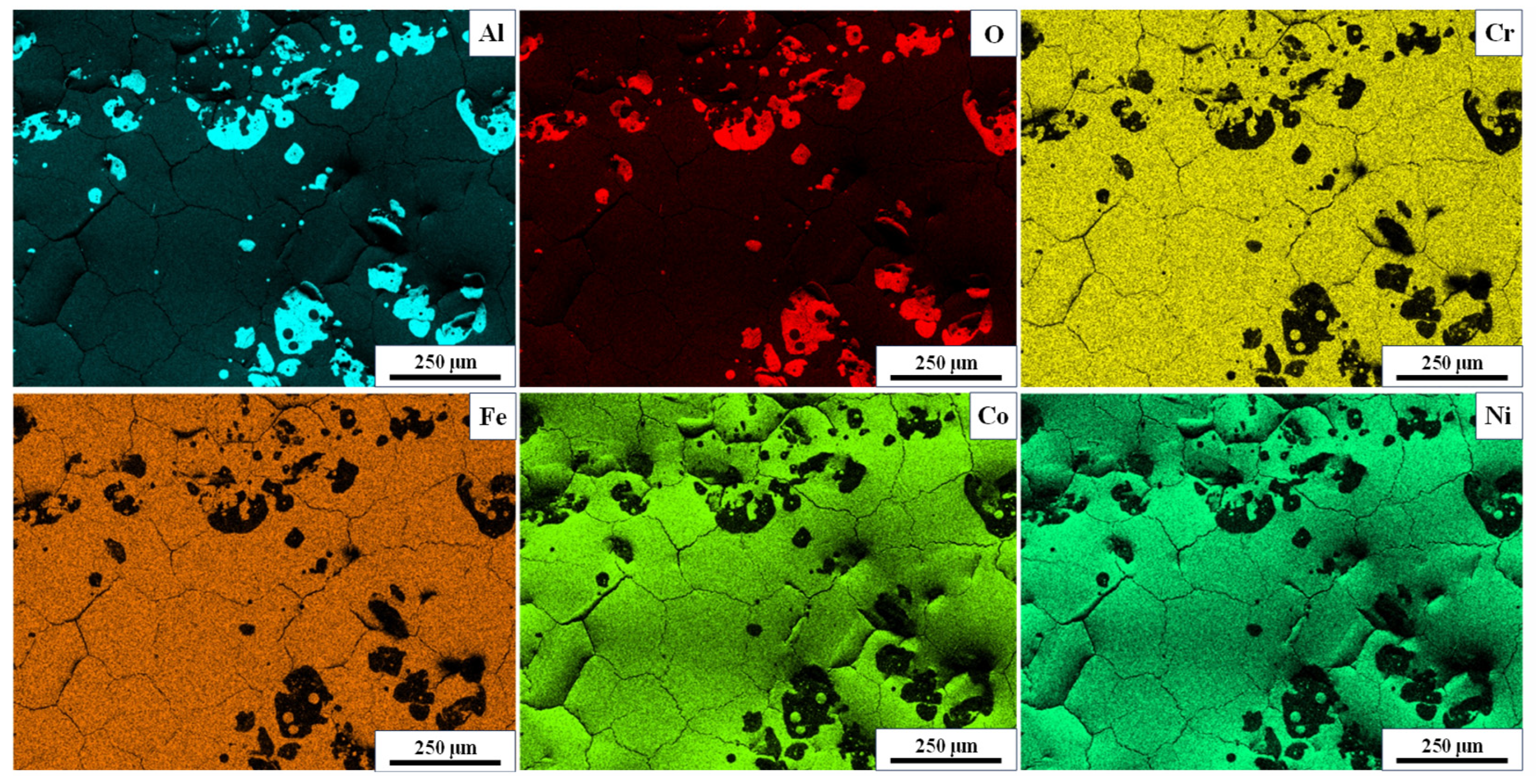
3.1. Microstructure of the AlCoCrFeNi Coating

As shown in Figure 2, the SEM images depict the surface and cross-section morphologies of the AlCoCrFeNi coating. There are many net-like micro-cracks on the surface of the AlCoCrFeNi coating due to the release of thermal stress. In the ESD process, the electrode and the substrate come into contact, immediately producing sparks which can melt part of the materials of the electrode and the substrate to form a melting pool on the surface of the substrate. Then, the melting pool solidifies swiftly at a speed of 105–106 K/s [24], producing thermal stress within the coating. When the thermal stress attains some extent, it will release through forming cracks. It also can be observed on the surface of the AlCoCrFeNi coating that there is some light stuff distributed on the coating. According to the EDS results of point A (Table 1), the light stuff contains a great amount of element O and Al, which suggests that the light stuff is enriched in Al2O3. Recent research proposed that although under the protection of argon, some coatings were oxidized by mixed oxygen, and Al in particular is easy to oxidize to form Al2O3 due to much more negative Gibbs free energy [25]. The EDS mapping results indicated that the ratio of every element of the AlCoCrFeNi coating is approximate to the equal atomic ratio, except for element O, as shown in Table 3. Moreover, the strong signals of Al and O of the light stuff also verify that Al2O3 formed in the process of the AlCoCrFeNi coating preparation.
An excellent bond is built between the AlCoCrFeNi coating and the H13 steel substrate, and the thickness of the AlCoCrFeNi coating is 50 ± 10 μm (Figure 2b). The microstructure inside the coating is compact and free of cracks, although there are net-like micro-cracks on the surface of the AlCoCrFeNi coating. The main element Fe of the H13 steel substrate and the other four elements of the AlCoCrFeNi coating have a gradient transition through the interface (Figure 2b), which is a typical feature of ESD coatings [26]. The EDS results of points (Table 3) indicate that the element Al in the AlCoCrFeNi coating has an obvious decrease in content in comparison to the electrode composition due to its low melting point as well as easy oxidation. From point D to G, the content of the element Fe increases gradually, and at the interface (point G) its content attains 48.74 at.% (Table 3), while that of the other four elements is gradually reduced, indicating that the elements of the electrode and the substrate have a mutual infiltration near the interface and form a strong metallurgical bond. The distribution of each element in the coating is shown in Figure 3.
Figure 4 shows the XRD pattern of the AlCoCrFeNi coating. As shown in Figure 4, the AlCoCrFeNi coating consists of a body-centered cubic (BCC) structure and a B2-structured Al-Ni intermetallic compound. The grain size of the AlCoCrFeNi coating was calculated using the Scheler formula [27]:
D = K λ α cos θ
where K = 0.89, λ is the X-ray wavelength (0.154 nm for Cu Kα), β is the full width at half maximum, and θ is the Bragg angle. The average grain size of the AlCoCrFeNi coating is 15.9 nm according to the calculated results, which suggests that a nanocrystalline microstructure forms in the AlCoCrFeNi coating.

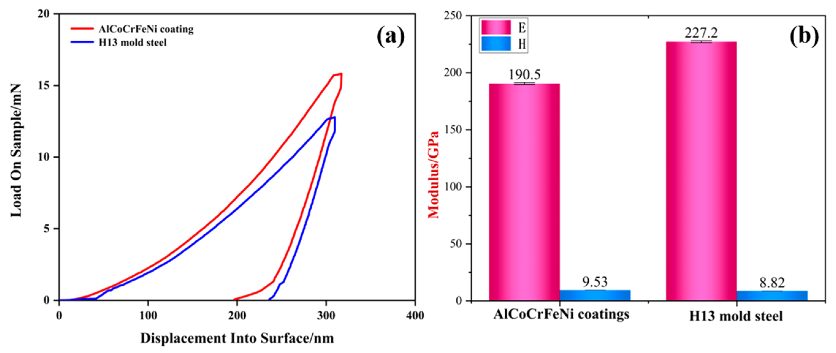
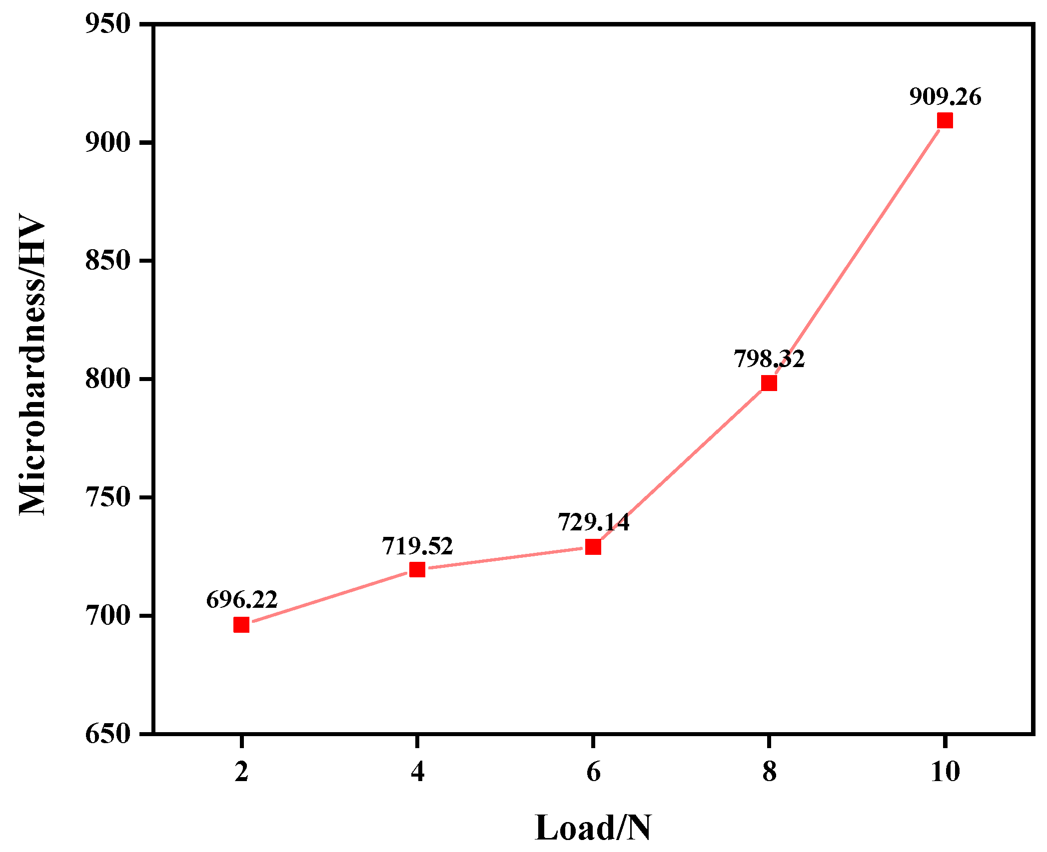
3.2. Nano-Mechanical Properties

Figure 5 shows the load–displacement curves and nano-mechanical properties of the AlCoCrFeNi coating and the H13 steel. As shown in Figure 5a, the AlCoCrFeNi coating was subjected to a larger load, which was approximately 1.2 times that of the H13 steel. The coating produced a smaller maximum displacement deformation during loading, and the residual deformation after complete unloading was similar in both tests. As shown in Figure 5b, the hardness of the AlCoCrFeNi coating is 9.53 GPa, and its elastic modulus is 190.5 GPa in the depth range of 100–200 nm. Comparatively, the hardness of the H13 steel is 8.82 GPa, and its elastic modulus is 227.2 GPa. The hardness of the AlCoCrFeNi coating exhibits an 8% increase, and its elastic modulus has a 16% decrease compared with the H13 steel. The H/E value of the AlCoCrFeNi coating increases by approximately 1.3 times, and the H3/E2 value of the AlCoCrFeNi coating increases by approximately 1.9 times compared with the substrate. The H/E and H3/E2 values are closely related with the tribological property of the material, and their increase is mainly due to both the increase in the hardness and the decrease in the elastic modulus of the AlCoCrFeNi coating.

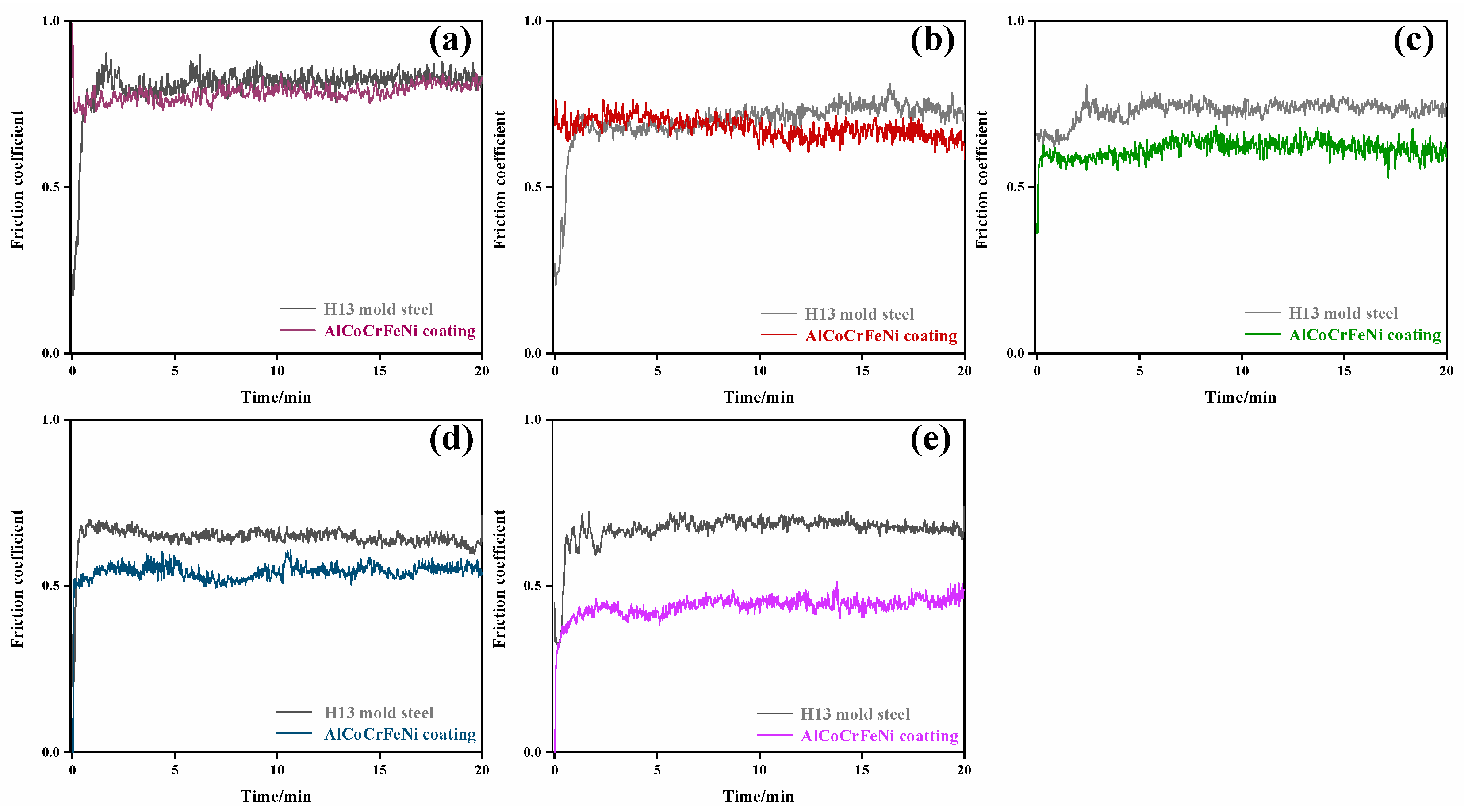
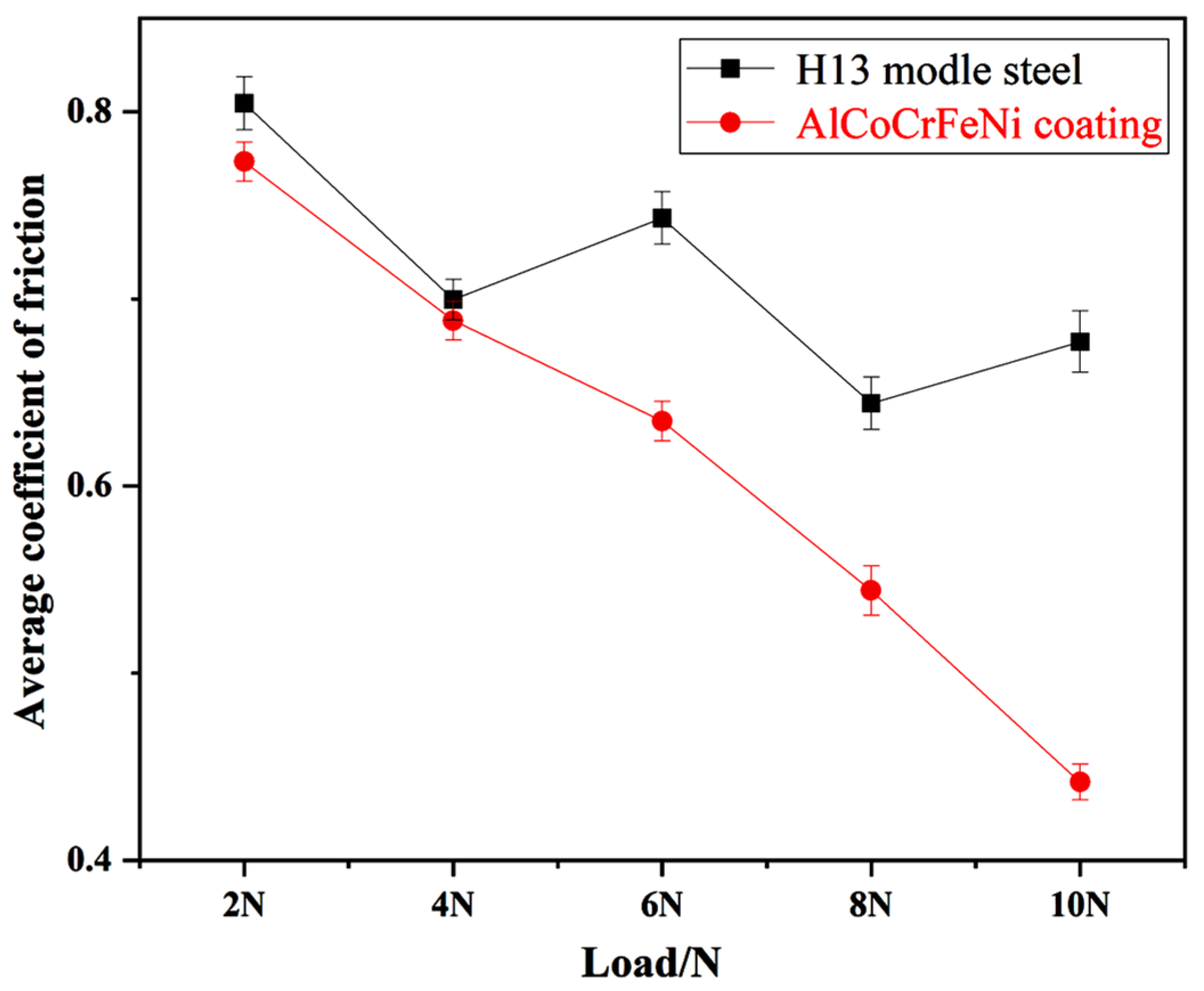
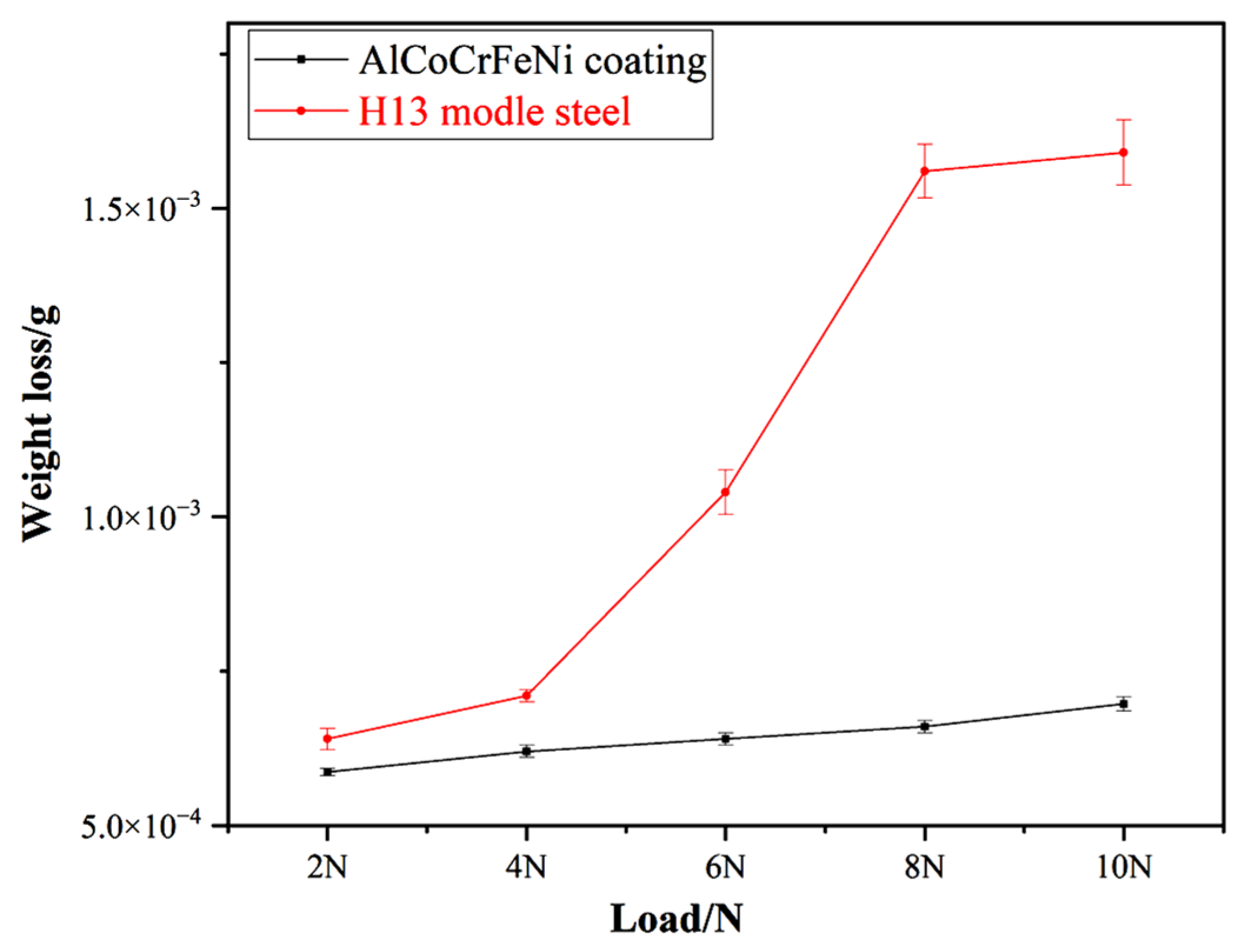
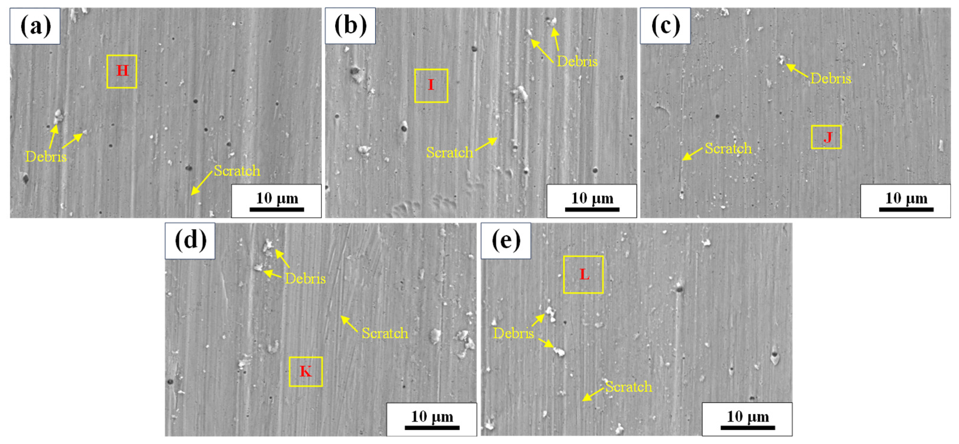
3.3. Tribological Properties

Figure 6 shows the friction coefficients of the AlCoCrFeNi coating and the H13 steel under different loads. Under a 2 N load (Figure 6a), the AlCoCrFeNi coating and H13 steel exhibit comparable steady-stage friction coefficients, though the coating shows an initial sharp increase due to its rough surface. At a 4 N load (Figure 6b), the friction coefficients of both materials remain similar for the first 10 min, after which the coating’s value becomes consistently lower than that of H13 steel. Under higher loads (6 N, 8 N, and 10 N) (Figure 6c–e), the AlCoCrFeNi coating demonstrates significantly lower friction coefficients than H13 steel, with the disparity amplifying as the load increases. Moreover, the gap between the friction coefficients of the AlCoCrFeNi coating and the H13 steel is the biggest, and the smallest friction coefficient of the AlCoCrFeNi coating appears under a load of 10 N. Figure 7 shows the change in the friction coefficients of the AlCoCrFeNi coating and the H13 steel with the load. As shown in Figure 7, the friction coefficient of the AlCoCrFeNi coating is reduced with the increase in the load, which presents a linear law of the friction coefficient and the load. Comparatively, the friction coefficient of the H13 steel is firstly reduced sharply from a load of 2 N to one of 4 N, and then fluctuates in the load range of 4 N to 10 N, which suggests that the load has little influence on the friction coefficient of the H13 steel in the load range of 4 N to 10 N.
Figure 8 shows the weight loss change in the AlCoCrFeNi coating and the H13 steel with load. As shown in Figure 8, the wear resistance of the AlCoCrFeNi coating increases greatly in comparison to the H13 steel under all loads. Moreover, the bigger the load, the more obvious the increase in the wear resistance. In addition, the change tendencies of the AlCoCrFeNi coating and the H13 steel are different. For the H13 steel, the weight loss increases slightly from a load of 2 N to one of 4 N and from 8 N to 10 N, and it does so greatly from 4 N to 8 N. For the AlCoCrFeNi coating, weight loss increases with load according to a linear law.
Figure 9 shows the worn morphologies of the H13 steel under different loads. As shown in Figure 9, severe material plastic deformation appears on the worn surface of the H13 steel, and there are also some pits indicating fatigue failure due to the reciprocating friction. Therefore, the main mechanism of the H13 steel can be characterized as severe adhesive wear. Figure 10 shows the worn morphologies of the AlCoCrFeNi coating under different loads. Different from the worn morphologies of the H13 steel, the surface of the AlCoCrFeNi coating has been ground smooth in comparison to the surface morphology of the as-deposited AlCoCrFeNi coating. Some scratches are distributed on the worn surface of the AlCoCrFeNi coating along the direction of the reciprocating friction. Therefore, the main mechanism of the AlCoCrFeNi coating belongs to micro-cutting abrasive wear.

4. Discussion

4.1. Enhancement of the Tribological Property of the H13 Steel via the ESD AlCoCrFeNi Coating

In an ESD process, the solidified speed can reach 105–106 K/s, and at such a rapid speed, the AlCoCrFeNi coating consists of a nanocrystalline microstructure with a grain size of 15.9 nm. Furthermore, a B2-structured Al-Ni intermetallic compound formed in the AlCoCrFeNi coating (Figure 4) due to the non-equilibrium solidification and the fine B2 phase precipitate can play a role in second phase strengthening [28]. The strengthening effect of both the fine grain and the second phase can greatly improve the hardness and strength of the AlCoCrFeNi coating, which is beneficial for resist plastic deformation or shear failure from adherent wear in comparison to the H13 steel (Figure 9). Furthermore, its smooth worn surface, which is free of pits or cracks (Figure 10), verifies the excellent tribological performance of the AlCoCrFeNi coating. Moreover, the strong metallurgical bond between the coating and the substrate (Figure 2b,c) can give the AlCoCrFeNi coating an excellent tribological performance under high load without spalling.
The values of H/E and H3/E2 are significant parameters for predicting the tribological property of a material [29]. The former decides the elasticity limit of the rubbing contact surface, and the latter represents the capability to resist plastic deformation under the action of contact load. With the increase in H/E value, the quantity of the asperities exceeding the elasticity limit is reduced on the friction contact surface under the action of load, thereby increasing wear resistance due to antifriction. The H/E and H3/E2 values of the AlCoCrFeNi coating increase remarkably in comparison to the H13 steel, indicating that the AlCoCrFeNi coating can enhance the tribological performance of the H13 steel.
Jin G et al. [30] proposed that oxidation behavior is a key factor affecting the overall wear resistance of HEAs, and the formed oxide layer on the worn surface can prevent direct contact between the friction pairs, thereby notably lowering the wear rate. Guo C et al. [31] also found that the oxide layer formed on the worn surface of the AlCoCrFeNi coating increases the tribological performance of the coating, and furthermore the fine grain size is beneficial for oxide layer formation under the effect of the heat produced by rubbing. Table 4 shows the EDS results of the regions (Figure 10) of the worn surface of the AlCoCrFeNi coatings under different loads, verifying that oxidation actually took place on the worn surface of the AlCoCrFeNi coatings.
According to the Archard law:
Q = K L N / H
where Q is the wear volume, N the applied load, L the total sliding distance, K the friction coefficient, and H the hardness of the wear surface. Compared with the H13 steel, the Q of the AlCoCrFeNi coating is greatly reduced when the K is reduced and the H increases while the L and N are constant. However, for the AlCoCrFeNi coating itself, the Archard law is broken for the nonlinear change in the hardness of the rubbing surface of the AlCoCrFeNi coating as well as the change in the wear mechanism. It is well known that the Archard law is established on the adhesive wear model.

4.2. Load Influence on the Tribological Property of the AlCoCrFeNi Coating

When the load on the contact surface of the AlCoCrFeNi coating increases, the stress between the friction pairs will increase and therefore the work hardening effect under the worn smooth surface of the coating will become strong. Figure 11 shows the microhardness change in the worn surface of the AlCoCrFeNi coatings under different loads. As shown in Figure 11, the microhardness of the AlCoCrFeNi coatings increases gradually from a load of 2 N to one of 6 N, and it does so sharply from a load of 6 N to one of 10 N, indicating that the work hardening sensitivity of the AlCoCrFeNi coatings becomes stronger at a critical load of 6 N, which suggests that the wear resistance of the AlCoCrFeNi coatings increases accordingly due to the increase in hardness. In addition, the work hardening may also reduce the friction coefficient [32,33].
Under increasing loads (see Table 4), the oxygen (O) content rises on the smooth worn surfaces of AlCoCrFeNi coatings. This indicates enhanced oxidation intensity at higher loads, where greater friction-generated heat elevates localized temperatures. The temperature increase correlates directly with load magnitude, demonstrating a causal relationship between applied load, oxidation, and thermal effects on the coating’s worn surface [34]. Furthermore, the oxide layer formed by nanocrystalline microstructure in the AlCoCrFeNi coatings always possesses good adherence, which can greatly increase the tribological performance of the AlCoCrFeNi coatings. The production of the oxide layer under a higher load will cause a reduction in the friction coefficient [35,36].
To sum up, both the work hardening and the oxide layer formed on the rubbing surface can reduce the friction coefficient of the AlCoCrFeNi coating with an increase in load, so the friction coefficient varies as a function of load as well as wear resistance.

5. Conclusions

An AlCoCrFeNi coating with a nanocrystalline microstructure is electrospark-deposited on a H13 steel substrate, and a gradient transition of elements between the coating and the substrate an excellent bond; the microstructure mainly consists of BCC and B2 phase structure.
The hardness of the AlCoCrFeNi coating exhibits an 8% increase and its elastic modulus has a 16% decrease compared with the H13 steel, and the H/E and H3/E2 values of the AlCoCrFeNi coating increase by approximately 1.3 and 1.9 times compared with the substrate, respectively.
The AlCoCrFeNi coating significantly improves the tribological performance of the H13 steel at a load of 2 N, 4 N, 6 N, 8 N, and 10 N, and its wear mechanism belongs to micro-cutting abrasive wear whilst that of the H13 steel can be characterized as severe adhesive wear.
This study demonstrates that ESD AlCoCrFeNi coatings significantly enhance the tribological performance of H13 steel under higher loads. The combination of a nanocrystalline microstructure, work hardening, and a tribo-oxidation layer provides a promising solution for extending the service life of industrial molds and cutting tools subjected to high-load wear conditions.

Author Contributions

Conceptualization, X.C., G.Z. and K.L.; writing—original draft preparation, K.L. and G.Z.; writing—review and editing, J.L., G.Z., H.S. and X.C.; investigation, K.L., C.G. and G.Z.; resources, H.S. and J.L.; data curation, K.L., X.C. and C.G.; project administration, C.G. and G.Z. All authors have read and agreed to the published version of the manuscript.

Funding

This research was funded by the Research Project of the Application Foundation of Liaoning Province of China (No. 2022JH2/101300006), the Research Project of the Education Department of Liaoning Province of China (LJKMZ20220604 and JYTQN2023068), the Special Fund of Basic Scientific Research Operating Expense for Undergraduate Universities in Liaoning Province (LJ212410144077), the Key Laboratory of Weapon Science & Technology Research (LJ232410144071), and the Light-Selection Team Plan of Shenyang Ligong University (SYLUGXTD5).

Data Availability Statement

The original contributions presented in the study are included in the article; further inquiries can be directed to the corresponding authors.

Acknowledgments

The authors thank the researchers of the School of Equipment Engineering, Shenyang Ligong University, for their guidance and help.

Conflicts of Interest

Author Ke Lv was employed by the company China Rongtong Resources Development Group Co., Ltd. Author Jie Li was employed by the company China Rongtong Resources Development Company 3305 Factory. The remaining authors declare that the research was conducted in the absence of any commercial or financial relationships that could be construed as a potential conflict of interest.

References

  1. Narvan, M.; Al-Rubaie, K.S.; Elbestawi, M. Process-Structure-Property Relationships of AISI H13 Tool Steel Processed with Selective Laser Melting. Materials 2019, 12, 2284. [Google Scholar] [CrossRef] [PubMed]
  2. Mazur, M.; Brincat, P.; Leary, M.; Brandt, M. Numerical and experimental evaluation of a conformally cooled H13 steel injection mould manufactured with selective laser melting. Int. J. Adv. Manuf. Technol. 2017, 93, 881–900. [Google Scholar] [CrossRef]
  3. Wang, M.; Wu, Y.; Wei, Q.; Shi, Y. Thermal Fatigue Properties of H13 Hot-Work Tool Steels Processed by Selective Laser Melting. Metals 2020, 10, 116. [Google Scholar] [CrossRef]
  4. Bae, K.; Moon, H.S.; Park, Y.; Jo, I.; Lee, J. Influence of Tempering Temperature and Time on Microstructure and Mechanical Properties of Additively Manufactured H13 Tool Steel. Materials 2022, 15, 8329. [Google Scholar] [CrossRef]
  5. Du, K.; Lv, Z.; Fan, W.; Zhang, R.; Li, X.; Xu, L. Effect of Heat Treatment Process on Microstructure and Mechanical Properties of High-Carbon H13 Steel. Processes 2023, 11, 3239. [Google Scholar] [CrossRef]
  6. Zhang, L.; Ma, G.; Fu, L.; Tian, J. Recent Progress in High-Entropy Alloys. Adv. Mater. Res. 2013, 227, 631–632. [Google Scholar] [CrossRef]
  7. Xu, X.; Guo, S.; Nieh, T.; Liu, C.; Hirata, A.; Chen, M. Effects of mixing enthalpy and cooling rate on phase formation of AlxCoCrCuFeNi high-entropy alloys. Materialia 2019, 6, 100292. [Google Scholar] [CrossRef]
  8. Nartita, R.; Ionita, D.; Demetrescu, I. A Modern Approach to HEAs: From Structure to Properties and Potential Applications. Crystals 2024, 14, 451. [Google Scholar] [CrossRef]
  9. Jeong, H.T.; Kim, W.J. Deformation Mechanisms and Processing Maps for High Entropy Alloys (Presentation of Processing Maps in Terms of Zener–Hollomon Parameter): Review. Materials 2023, 16, 919. [Google Scholar] [CrossRef]
  10. Zhang, Q.; Li, M.; Wang, Q.; Qi, F.; Kong, M.; Han, B. Investigation of the Microstructure and Properties of CoCrFeNiMo High-Entropy Alloy Coating Prepared through High-Speed Laser Cladding. Coatings 2023, 13, 1211. [Google Scholar] [CrossRef]
  11. Ma, S.; Zhang, C.; Li, L.; Yang, Y. Microstructure and Properties of CoCrFeNiMnTix High-Entropy Alloy Coated by Laser Cladding. Coatings 2024, 14, 620. [Google Scholar] [CrossRef]
  12. Wu, T.; Chen, Y.; Shi, S.; Wu, M.; Gui, W.; Tan, Y.; Li, J.; Wu, Y. Effects of W Alloying on the Lattice Distortion and Wear Behavior of Laser Cladding AlCoCrFeNiWx High-Entropy Alloy Coatings. Materials 2021, 14, 5450. [Google Scholar] [CrossRef]
  13. Lu, K.; Zhu, J.; Ge, W.; Hui, X. Progress on New Preparation Methods, Microstructures, and Protective Properties of High-Entropy Alloy Coatings. Coatings 2022, 12, 1472. [Google Scholar] [CrossRef]
  14. Wang, H.; Kang, J.; Yue, W.; Jin, G.; Li, R.; Zhou, Y.; Liang, J.; Yang, Y. Microstructure and Corrosive Wear Properties of CoCrFeNiMn High-Entropy Alloy Coatings. Materials 2023, 16, 55. [Google Scholar] [CrossRef]
  15. Li, T.; Liu, Y.; Liu, B.; Guo, W.; Xu, L. Microstructure and Wear Behavior of FeCoCrNiMo0.2 High Entropy Coatings Prepared by Air Plasma Spray and the High Velocity Oxy-Fuel Spray Processes. Coatings 2017, 7, 151. [Google Scholar] [CrossRef]
  16. Zhang, L.; Shi, Y.; Ye, Q.; Yang, B. Enhanced Corrosion-Resistance of AlTiCrFeMoSi High−Entropy Alloy Coating by Magnetron Sputtering. Coatings 2023, 13, 332. [Google Scholar] [CrossRef]
  17. Li, Z.; Jing, C.; Feng, Y.; Wu, Z.; Lin, T.; Zhao, J. Phase evolution and properties of AlxCoCrFeNi high-entropy alloys coatings by laser cladding. Mater. Today Commun. 2023, 35, 105800. [Google Scholar] [CrossRef]
  18. Wang, Y.; Nie, C.; Wang, S.; Gong, P.; Zhang, M.; Hu, Z.; Li, B. Study on the Properties of TiC Coating Deposited by Spark Discharge on the Surface of AlFeCoCrNiCu High-Entropy Alloy. Materials 2024, 17, 4110. [Google Scholar] [CrossRef]
  19. Geambazu, L.E.; Cotrut, C.M.; Miculescu, F.; Csaki, I. Mechanically Alloyed CoCrFeNiMo0.85 High-Entropy Alloy for Corrosion Resistance Coatings. Materials 2021, 14, 3802. [Google Scholar] [CrossRef]
  20. Yang, H.; Chen, X.; Chen, L.; Wang, Z.; Hou, G.; Guo, C.; Zhang, J. Influence of temperature on tribological behavior of AlCoCrFeNi coatings prepared by electrospark deposition. Dig. J. Nanomater. Biostruct. 2023, 18, 145–156. [Google Scholar] [CrossRef]
  21. Wang, Z.; Zhu, G.; Lu, F.; Zhang, L.; Wang, Y.; Zhao, S.; Zhang, J. Friction and Wear Performance of an Electrospark-Deposited Ta Coating on CrNi3MoVA ST. Mater. Technol. 2024, 58, 17–23. [Google Scholar] [CrossRef]
  22. Barile, C.; Casavola, C.; Pappalettera, G.; Renna, G. Advancements in Electrospark Deposition (ESD) Technique: A Short Review. Coatings 2022, 12, 1536. [Google Scholar] [CrossRef]
  23. Leo, P.; Renna, G.; Casalino, G. Study of the Direct Metal Deposition of AA2024 by ElectroSpark for Coating and Reparation Scopes. Appl. Sci. 2017, 7, 945. [Google Scholar] [CrossRef]
  24. Guo, C.; Liang, T.; Lu, F.; Liang, Z.; Zhao, S.; Zhang, J. Isothermal Oxidation Behavior of Electrosparkdeposited NiCrAlY Coatings on a NI-Based Single-Crystal Superalloy. Mater. Technol. 2019, 53, 389–394. [Google Scholar]
  25. Zhang, W.; Zhang, J.; Wang, H.; Lou, W.; Liu, X. Influences of Cr and Co on the Growth of Thermally Grown Oxide in Thermal Barrier Coating during High-Temperature Exposure. Coatings 2018, 8, 195. [Google Scholar] [CrossRef]
  26. Wang, W.; Du, M.; Zhang, X.; Luan, C.; Tian, Y. Preparation and Properties of Mo Coating on H13 Steel by Electro Spark Deposition Process. Materials 2021, 14, 3700. [Google Scholar] [CrossRef]
  27. Deutsch, S. High Pressure Phase Transformations in Polycrystalline Yttrium Oxide. Ph.D. Thesis, Rutgers, The State University of New Jersey, New Brunswick, NJ, USA, 2012. [Google Scholar]
  28. Gwalani, B.; Torgerson, T.; Dasari, S.; Jagetia, A.; Nartu, M.-Y.; Gangireddy, S.; Pole, M.; Wang, T.; Scharf, T.W.; Banerjee, R. Influence of fine-scale B2 precipitation on dynamic compression and wear properties in hypo-eutectic Al0.5CoCrFeNi high-entropy alloy. J. Alloys Compd. 2021, 853, 157126. [Google Scholar] [CrossRef]
  29. Lozynskyi, V.; Trembach, B.; Hossain, M.M.; Kabir, M.H.; Silchenko, Y.; Krbata, M.; Sadovyi, K.; Kolomiitse, O.; Ropyak, L. Prediction of phase composition and mechanical properties Fe-Cr-C-B-Ti-Cu hardfacing alloys: Modeling and experimental Validations. Heliyon 2024, 10, e25199. [Google Scholar] [CrossRef]
  30. Jin, G.; Cai, Z.; Guan, Y.; Cui, X.; Liu, Z.; Li, Y.; Dong, M.; Zhang, D. High temperature wear performance of laser-cladded FeNiCoAlCu high-entropy alloy coating. Appl. Surf. Sci. 2018, 445, 113. [Google Scholar] [CrossRef]
  31. Guo, C.A.; Zhao, Z.K.; Lu, F.S. Performance of high-speed friction and wear of electrospark deposited AlCoCrFeNi high-entropy. Dig. J. Nanomater. Biostructures 2018, 13, 931–939. [Google Scholar]
  32. Stott, F.H.; Jordan, M.P. The effects of load and substrate hardness on the development and maintenance of wear-protective layers during sliding at elevated temperatures. Wear 2001, 250, 391–400. [Google Scholar] [CrossRef]
  33. Betancourt-Dougherty, L.C.; Smith, R.W. Effects of load and sliding speed on the wear behaviour of plasma sprayed TiC-NiCrBSi coatings. Wear 1998, 217, 147–154. [Google Scholar] [CrossRef]
  34. Zurcher, T.; Bouvard, G.; Abry, J.-C.; Charkaluk, E.; Fridrici, V. Effect of the scanning strategy and tribological conditions on the wear resistance of IN718 obtained by Laser Metal Deposition. Wear 2023, 534, 205152. [Google Scholar] [CrossRef]
  35. Kato, K. Wear in relation to friction—A review. Wear 2000, 241, 151–157. [Google Scholar] [CrossRef]
  36. Telasang, G.; Majumdar, J.D.; Padmanabham, G.; Manna, I. Wear and corrosion behavior of laser surface engineered AISI H13 hot working tool steel. Surf. Coat. Technol. 2015, 261, 69–78. [Google Scholar] [CrossRef]
Figure 1. Schematic of the device used for the reciprocating friction and wear test.
Metals 15 00649 g001
Figure 2. SEM images of the surface (a), cross-section morphologies (b), and line EDS results of the AlCoCrFeNi coating (c).
Metals 15 00649 g002
Figure 3. Mapping images of the EDS results of the AlCoCrFeNi coating.
Metals 15 00649 g003
Figure 4. XRD pattern of AlCoCrFeNi coating.
Metals 15 00649 g004
Figure 5. Load–displacement curves (a) and nano-mechanical properties (b) of the AlCoCrFeNi coating and the H13 steel.
Metals 15 00649 g005
Figure 6. Friction coefficients of the AlCoCrFeNi coating and the H13 steel under a load of (a) 2 N, (b) 4 N, (c) 6 N, (d) 8 N, and (e) 10 N.
Metals 15 00649 g006
Figure 7. Change in the friction coefficients of the AlCoCrFeNi coating and the H13 steel with load.
Metals 15 00649 g007
Figure 8. Weight loss change of the AlCoCrFeNi coating and the H13 steel with load.
Metals 15 00649 g008
Figure 9. Worn morphologies of the H13 steel under a load of (a) 2 N, (b) 4 N, (c) 6 N, (d) 8 N, and (e) 10 N.
Metals 15 00649 g009
Figure 10. Worn morphologies of the AlCoCrFeNi coating under a load of (a) 2 N, (b) 4 N, (c) 6 N, (d) 8 N, and (e) 10 N.
Metals 15 00649 g010
Figure 11. Microhardness change in the worn surface of the AlCoCrFeNi coatings under different loads.
Metals 15 00649 g011
Table 1. Chemical composition of H13 steel (wt.%).
ElementCrMoSiVCMnSPFe
Content5.01.300.950.920.40.350.050.03Bal.
Table 2. Process parameters of AlCoCrFeNi coating.
PowerElectrode Rotation SpeedArgon Flow RateSpecific Deposition Time
800 W2000 r/min15 L/min2.5 min/cm2
Table 3. EDS results of the points and area of the AlCoCrFeNi coating.
O (at.%)Al (at.%)Cr (at.%)Fe (at.%)Co (at.%)Ni (at.%)
Area Figure 2a8.7919.7418.8718.1717.4917.03
Point A66.4533.020.350.080.070.04
Point B-18.3919.6021.7919.7620.46
Point C-17.8319.3322.3719.7420.73
Point D-15.9120.5822.2220.2721.02
Point E-14.2618.4132.8017.5217.01
Point F-13.0918.2134.2217.2317.25
Point G-12.5113.8048.7412.7712.18
Table 4. EDS results of the regions of the smooth worn surface of the AlCoCrFeNi coatings under different loads.
O (at.%)Al (at.%)Cr (at.%)Fe (at.%)Co (at.%)Ni (at.%)
Point H2.5718.6619.5420.0819.4019.74
Point I2.7215.6920.2820.4520.4220.44
Point J3.1620.3019.0719.3719.0919.02
Point K3.5717.6319.4121.0318.9519.41
Point L3.7517.9319.2420.6619.2319.19
Disclaimer/Publisher’s Note: The statements, opinions and data contained in all publications are solely those of the individual author(s) and contributor(s) and not of MDPI and/or the editor(s). MDPI and/or the editor(s) disclaim responsibility for any injury to people or property resulting from any ideas, methods, instructions or products referred to in the content.

