

Numerical and Geometrical Evaluation of Steel Plates with Transverse Hat-Stiffeners Under Bending


 ,
,  and
and 
Abstract
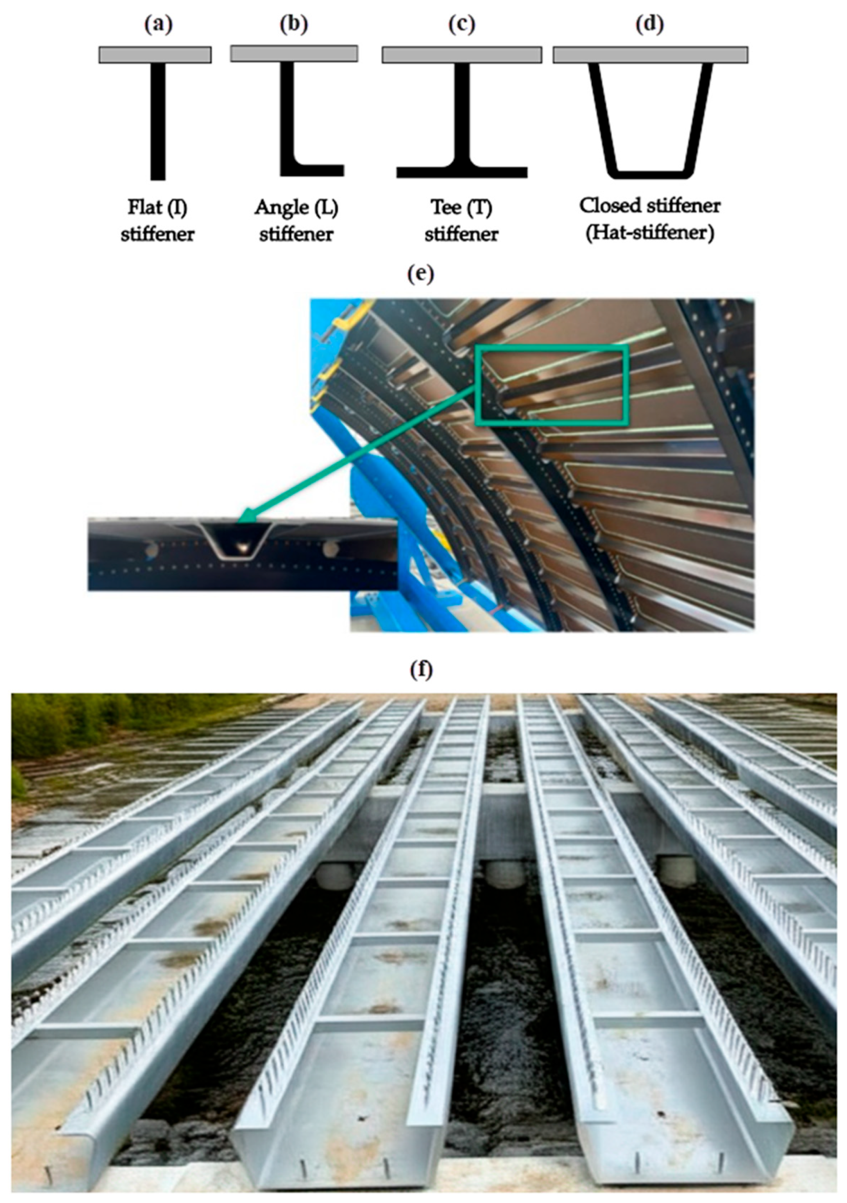
1. Introduction
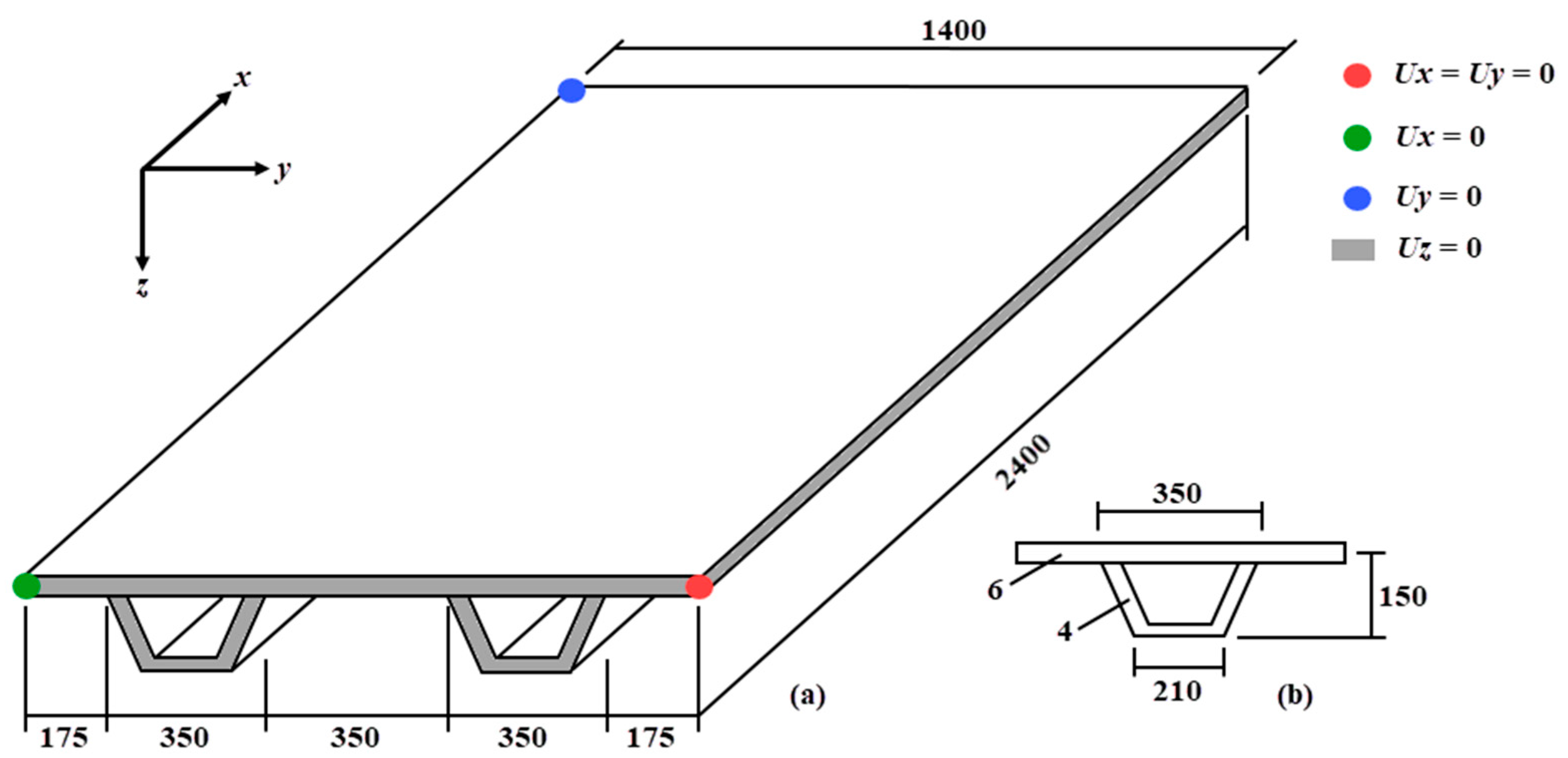
2. Materials and Methods
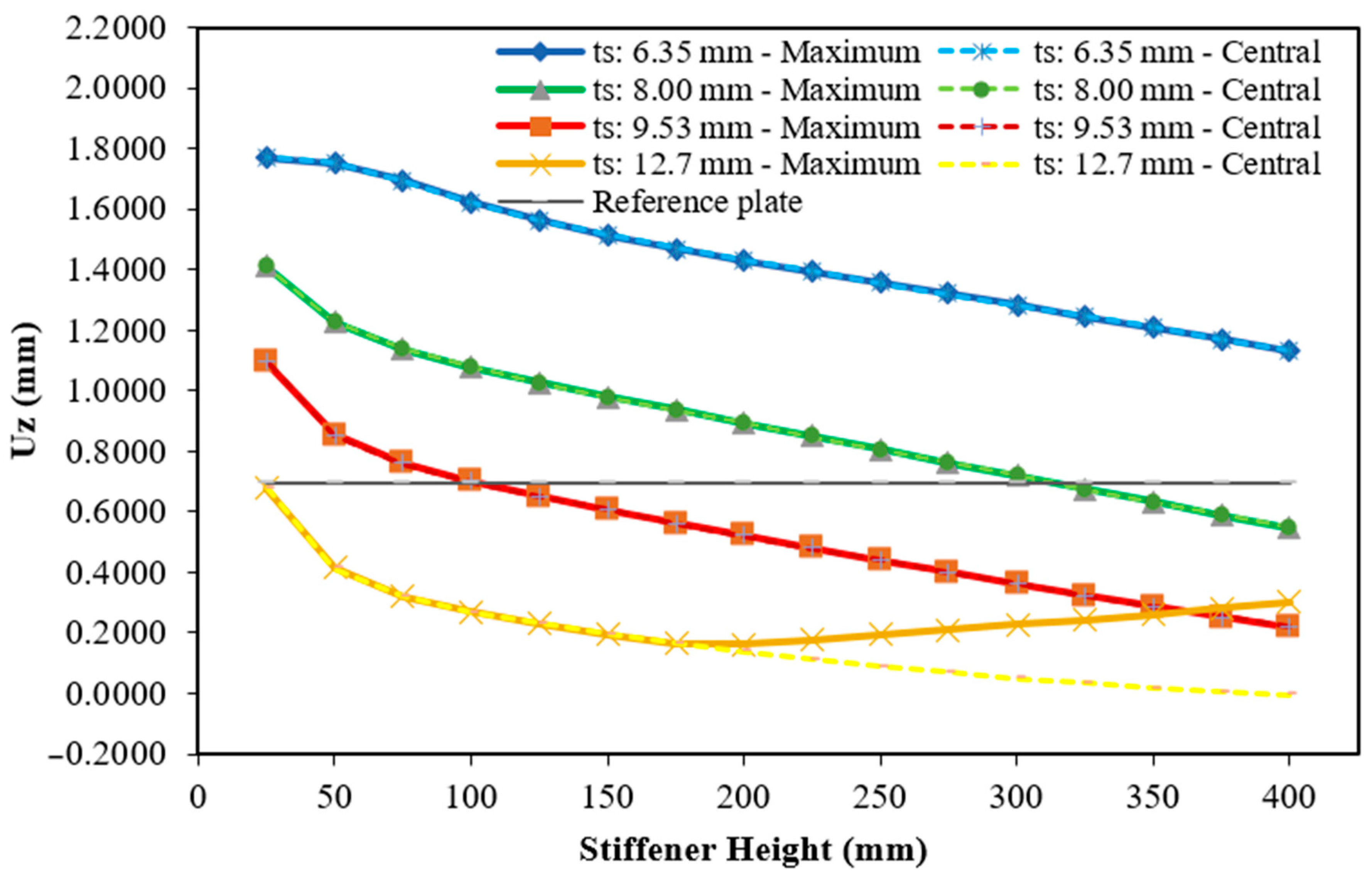
3. Results and Discussions
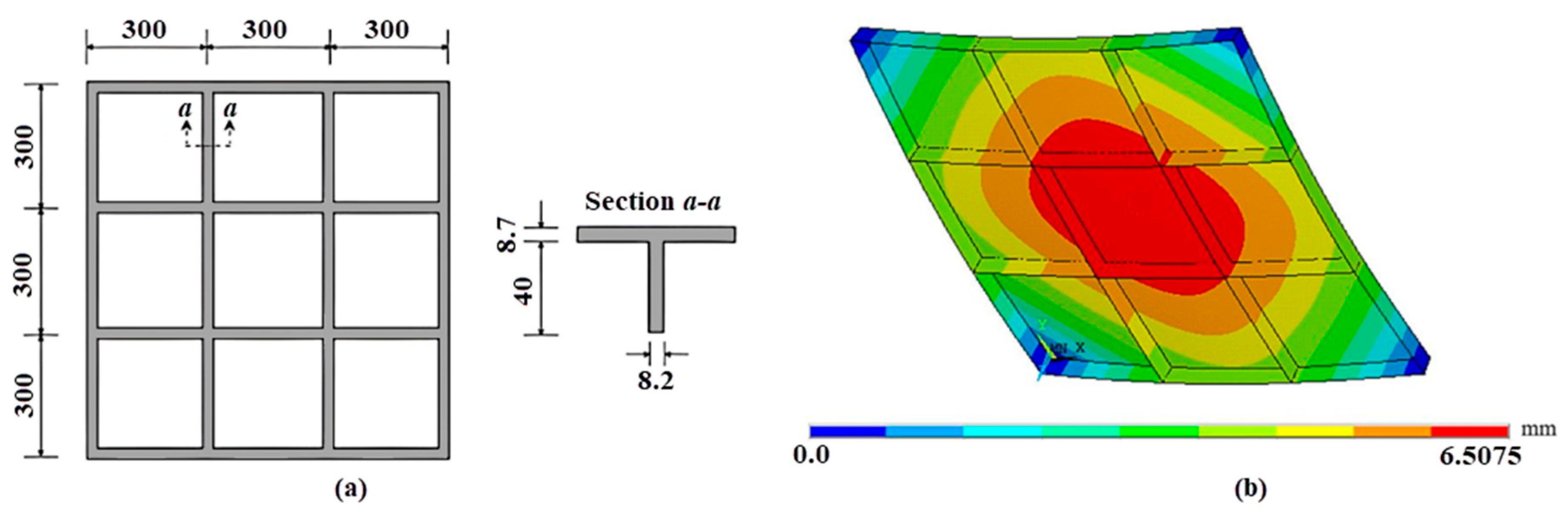
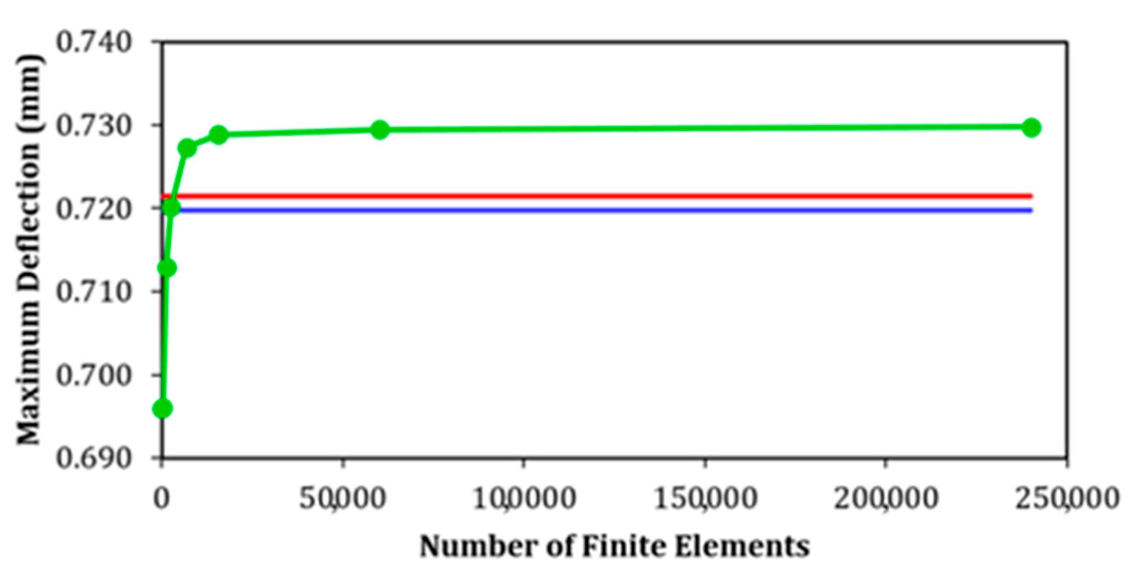
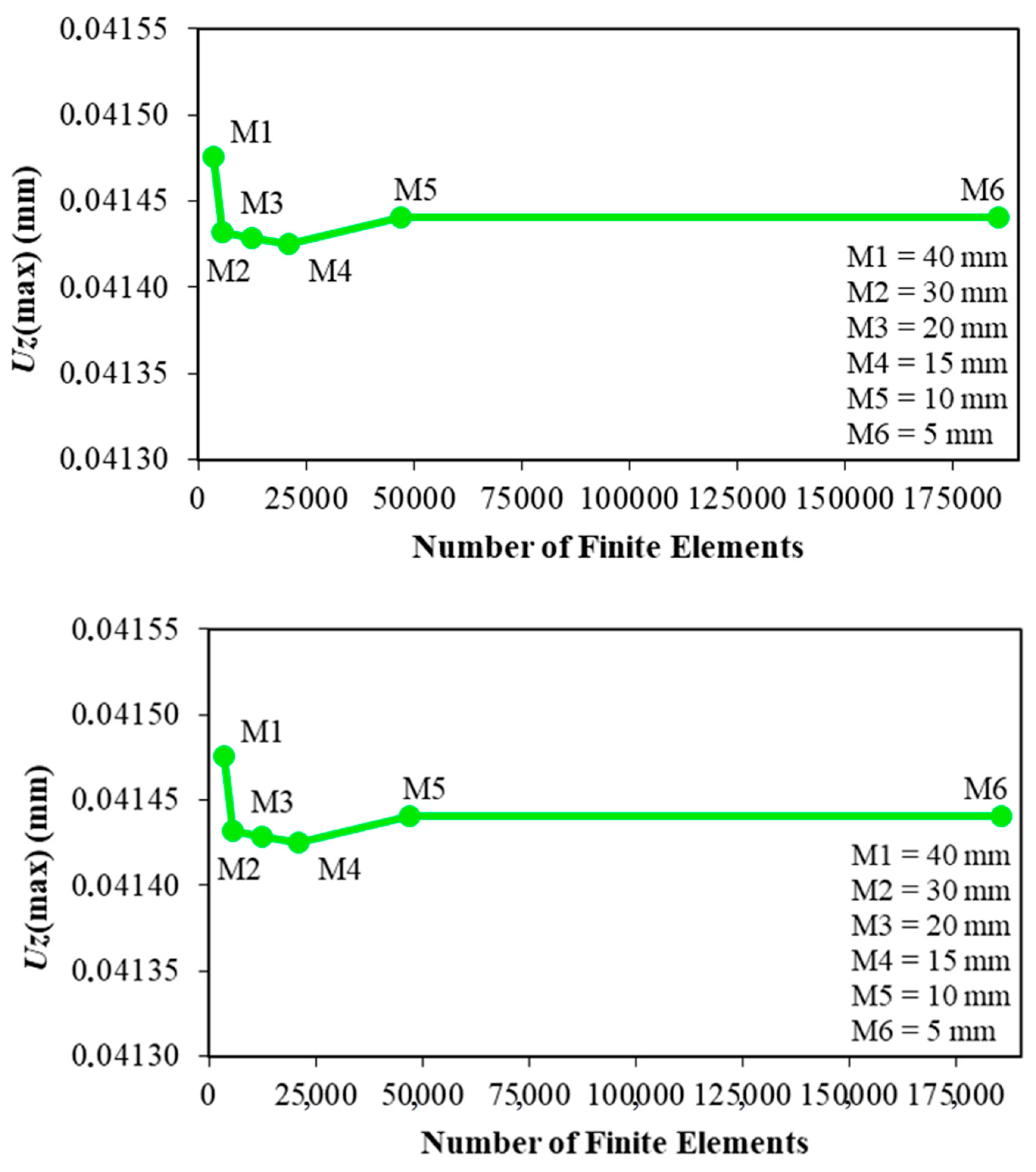
3.1. Computational Model Validation and Verification
3.2. Case Study
3.3. Comparison Between Plates Reinforced with Transverse or Longitudinal Hat-Stiffeners
4. Conclusions
Author Contributions
Funding
Data Availability Statement
Acknowledgments
Conflicts of Interest
Appendix A

| hs (mm) | ts (mm) | (mm) | (mm) | RD (%) |
|---|---|---|---|---|
| 400 | 6.35 | 1.1309 | 1.1310 | 0.005 |
| 375 | 6.35 | 1.1700 | 1.1700 | −0.003 |
| 350 | 6.35 | 1.2083 | 1.2084 | 0.007 |
| 325 | 6.35 | 1.2462 | 1.2461 | −0.004 |
| 300 | 6.35 | 1.2833 | 1.2834 | 0.006 |
| 275 | 6.35 | 1.3202 | 1.3202 | −0.003 |
| 250 | 6.35 | 1.3569 | 1.3569 | 0.003 |
| 225 | 6.35 | 1.3938 | 1.3939 | 0.007 |
| 200 | 6.35 | 1.4316 | 1.4316 | −0.003 |
| 175 | 6.35 | 1.4713 | 1.4713 | 0.003 |
| 150 | 6.35 | 1.5146 | 1.5146 | −0.002 |
| 125 | 6.35 | 1.5644 | 1.5645 | 0.004 |
| 100 | 6.35 | 1.6248 | 1.6248 | 0.002 |
| 75 | 6.35 | 1.6953 | 1.6954 | 0.005 |
| 50 | 6.35 | 1.7542 | 1.7542 | 0.002 |
| 25 | 6.35 | 1.7712 | 1.7712 | 0.002 |
| 400 | 8.00 | 0.5481 | 0.5481 | 0.000 |
| 375 | 8.00 | 0.5906 | 0.5907 | 0.014 |
| 350 | 8.00 | 0.6337 | 0.6337 | 0.000 |
| 325 | 8.00 | 0.6767 | 0.6768 | 0.012 |
| 300 | 8.00 | 0.7201 | 0.7201 | 0.000 |
| 275 | 8.00 | 0.7634 | 0.7635 | 0.010 |
| 250 | 8.00 | 0.8067 | 0.8067 | 0.000 |
| 225 | 8.00 | 0.8500 | 0.8501 | 0.009 |
| 200 | 8.00 | 0.8933 | 0.8934 | 0.009 |
| 175 | 8.00 | 0.9370 | 0.9370 | 0.000 |
| 150 | 8.00 | 0.9812 | 0.9813 | 0.008 |
| 125 | 8.00 | 1.0274 | 1.0274 | −0.001 |
| 100 | 8.00 | 1.0776 | 1.0777 | 0.006 |
| 75 | 8.00 | 1.1383 | 1.1383 | 0.000 |
| 50 | 8.00 | 1.2264 | 1.2265 | 0.007 |
| 25 | 8.00 | 1.4100 | 1.4100 | 0.001 |
| 400 | 9.53 | 0.2203 | 0.2203 | 0.000 |
| 375 | 9.53 | 0.2537 | 0.2538 | 0.024 |
| 350 | 9.53 | 0.2887 | 0.2887 | 0.000 |
| 325 | 9.53 | 0.3248 | 0.3249 | 0.018 |
| 300 | 9.53 | 0.3623 | 0.3623 | 0.000 |
| 275 | 9.53 | 0.4007 | 0.4008 | 0.017 |
| 250 | 9.53 | 0.4401 | 0.4401 | 0.000 |
| 225 | 9.53 | 0.4803 | 0.4803 | 0.000 |
| 200 | 9.53 | 0.5212 | 0.5213 | 0.015 |
| 175 | 9.53 | 0.5630 | 0.5630 | 0.000 |
| 150 | 9.53 | 0.6059 | 0.6060 | 0.012 |
| 125 | 9.53 | 0.6508 | 0.6508 | 0.000 |
| 100 | 9.53 | 0.6998 | 0.6999 | 0.011 |
| 75 | 9.53 | 0.7599 | 0.7599 | 0.000 |
| 50 | 9.53 | 0.8545 | 0.8546 | 0.008 |
| 25 | 9.53 | 1.0965 | 1.0965 | −0.002 |
| 400 | 12.7 | 0.2999 | −0.0049 | −101.644 |
| 375 | 12.7 | 0.2810 | 0.0057 | −97.989 |
| 350 | 12.7 | 0.2625 | 0.0185 | −92.967 |
| 325 | 12.7 | 0.2445 | 0.0334 | −86.337 |
| 300 | 12.7 | 0.2269 | 0.0505 | −77.756 |
| 275 | 12.7 | 0.2100 | 0.0696 | −66.856 |
| 250 | 12.7 | 0.1939 | 0.0908 | −53.192 |
| 225 | 12.7 | 0.1787 | 0.1140 | −36.233 |
| 200 | 12.7 | 0.1647 | 0.1392 | −15.461 |
| 175 | 12.7 | 0.1666 | 0.1666 | 0.030 |
| 150 | 12.7 | 0.1966 | 0.1966 | 0.000 |
| 125 | 12.7 | 0.2299 | 0.2300 | 0.026 |
| 100 | 12.7 | 0.2692 | 0.2693 | 0.022 |
| 75 | 12.7 | 0.3218 | 0.3218 | 0.000 |
| 50 | 12.7 | 0.4138 | 0.4139 | 0.014 |
| 25 | 12.7 | 0.6799 | 0.6799 | 0.000 |
| hs (mm) | ts (mm) | (mm) | (mm) | RD (%) |
|---|---|---|---|---|
| 250 | 6.35 | 0.1646 | −0.0107 | −106.521 |
| 225 | 6.35 | 0.1894 | −0.0125 | −106.616 |
| 200 | 6.35 | 0.2163 | −0.0119 | −105.515 |
| 175 | 6.35 | 0.2458 | −0.0088 | −103.560 |
| 150 | 6.35 | 0.2793 | −0.0025 | −100.899 |
| 125 | 6.35 | 0.3188 | 0.0079 | −97.515 |
| 100 | 6.35 | 0.3670 | 0.0255 | −93.060 |
| 75 | 6.35 | 0.4245 | 0.0578 | −86.382 |
| 50 | 6.35 | 0.4853 | 0.1277 | −73.678 |
| 25 | 6.35 | 0.5790 | 0.3262 | −43.656 |
| 250 | 8.00 | 0.0612 | 0.0612 | 0.000 |
| 225 | 8.00 | 0.0545 | 0.0466 | −14.532 |
| 200 | 8.00 | 0.0702 | 0.0345 | −50.940 |
| 175 | 8.00 | 0.0882 | 0.0252 | −71.435 |
| 150 | 8.00 | 0.1086 | 0.0193 | −82.190 |
| 125 | 8.00 | 0.1323 | 0.0180 | −86.411 |
| 100 | 8.00 | 0.1611 | 0.0234 | −85.485 |
| 75 | 8.00 | 0.1989 | 0.0415 | −79.146 |
| 50 | 8.00 | 0.2556 | 0.0911 | −64.347 |
| 25 | 8.00 | 0.3690 | 0.2500 | −32.246 |
| 250 | 9.53 | 0.1404 | 0.1404 | 0.000 |
| 225 | 9.53 | 0.1192 | 0.1192 | 0.000 |
| 200 | 9.53 | 0.1003 | 0.1003 | 0.040 |
| 175 | 9.53 | 0.0839 | 0.0839 | 0.000 |
| 150 | 9.53 | 0.0705 | 0.0705 | 0.043 |
| 125 | 9.53 | 0.0612 | 0.0612 | 0.000 |
| 100 | 9.53 | 0.0793 | 0.0581 | −26.796 |
| 75 | 9.53 | 0.1066 | 0.0662 | −37.923 |
| 50 | 9.53 | 0.1515 | 0.1009 | −33.415 |
| 25 | 9.53 | 0.2566 | 0.2269 | −11.580 |
| 200 | 12.7 | 0.2107 | 0.2107 | 0.000 |
| 175 | 12.7 | 0.1864 | 0.1864 | 0.027 |
| 150 | 12.7 | 0.1645 | 0.1646 | 0.030 |
| 125 | 12.7 | 0.1462 | 0.1462 | 0.000 |
| 100 | 12.7 | 0.1326 | 0.1327 | 0.038 |
| 75 | 12.7 | 0.1280 | 0.1280 | 0.000 |
| 50 | 12.7 | 0.1436 | 0.1437 | 0.028 |
| 25 | 12.7 | 0.2282 | 0.2282 | 0.000 |
| hs (mm) | ts (mm) | (mm) | (mm) | RD (%) |
|---|---|---|---|---|
| 250 | 6.35 | 0.0252 | 0.0227 | −9.905 |
| 225 | 6.35 | 0.0326 | 0.0303 | −6.882 |
| 200 | 6.35 | 0.0416 | 0.0394 | −5.405 |
| 175 | 6.35 | 0.0528 | 0.0499 | −5.527 |
| 150 | 6.35 | 0.0668 | 0.0620 | −7.203 |
| 125 | 6.35 | 0.0847 | 0.0759 | −10.436 |
| 100 | 6.35 | 0.1080 | 0.0928 | −14.077 |
| 75 | 6.35 | 0.1369 | 0.1176 | −14.100 |
| 50 | 6.35 | 0.1710 | 0.1692 | −1.093 |
| 25 | 6.35 | 0.3169 | 0.3170 | 0.009 |
| 200 | 8.00 | 0.0336 | 0.0130 | −61.399 |
| 175 | 8.00 | 0.0277 | 0.0177 | −35.960 |
| 150 | 8.00 | 0.0268 | 0.0246 | −8.427 |
| 125 | 8.00 | 0.0362 | 0.0339 | −6.272 |
| 100 | 8.00 | 0.0494 | 0.0469 | −5.022 |
| 75 | 8.00 | 0.0689 | 0.0668 | −3.063 |
| 50 | 8.00 | 0.1055 | 0.1055 | 0.019 |
| 25 | 8.00 | 0.2184 | 0.2184 | 0.000 |
| 175 | 9.53 | 0.0497 | 0.0128 | −74.139 |
| 150 | 9.53 | 0.0422 | 0.0156 | −62.989 |
| 125 | 9.53 | 0.0379 | 0.0212 | −44.093 |
| 100 | 9.53 | 0.0380 | 0.0305 | −19.700 |
| 75 | 9.53 | 0.0463 | 0.0463 | 0.000 |
| 50 | 9.53 | 0.0788 | 0.0788 | 0.013 |
| 25 | 9.53 | 0.1750 | 0.1750 | −0.006 |
| 125 | 12.7 | 0.0678 | 0.0226 | −66.603 |
| 100 | 12.7 | 0.0616 | 0.0266 | −56.913 |
| 75 | 12.7 | 0.0630 | 0.0374 | −40.638 |
| 50 | 12.7 | 0.0799 | 0.0629 | −21.252 |
| 25 | 12.7 | 0.1497 | 0.1410 | −5.851 |
| hs (mm) | ts (mm) | (mm) | (mm) | RD (%) |
|---|---|---|---|---|
| 150 | 6.35 | 0.0283 | 0.0162 | −42.640 |
| 125 | 6.35 | 0.0369 | 0.0190 | −48.563 |
| 100 | 6.35 | 0.0488 | 0.0254 | −47.961 |
| 75 | 6.35 | 0.0648 | 0.0391 | −39.698 |
| 50 | 6.35 | 0.0992 | 0.0729 | −26.592 |
| 25 | 6.35 | 0.2115 | 0.1882 | −11.049 |
| 150 | 8.00 | 0.0263 | 0.0263 | 0.000 |
| 125 | 8.00 | 0.0253 | 0.0253 | 0.040 |
| 100 | 8.00 | 0.0306 | 0.0283 | −7.800 |
| 75 | 8.00 | 0.0445 | 0.0381 | −14.398 |
| 50 | 8.00 | 0.0743 | 0.0650 | −12.604 |
| 25 | 8.00 | 0.1642 | 0.1578 | −3.886 |
| 125 | 9.53 | 0.0350 | 0.0350 | 0.057 |
| 100 | 9.53 | 0.0349 | 0.0349 | 0.000 |
| 75 | 9.53 | 0.0420 | 0.0420 | 0.000 |
| 50 | 9.53 | 0.0651 | 0.0649 | −0.384 |
| 25 | 9.53 | 0.1464 | 0.1464 | 0.000 |
| 100 | 12.7 | 0.0539 | 0.0539 | −0.019 |
| 75 | 12.7 | 0.0539 | 0.0539 | 0.000 |
| 50 | 12.7 | 0.0707 | 0.0707 | 0.014 |
| 25 | 12.7 | 0.1383 | 0.1383 | 0.000 |
| hs (mm) | ts (mm) | (mm) | (mm) | RD (%) |
|---|---|---|---|---|
| 150 | 6.35 | 0.0211 | 0.0212 | 0.047 |
| 125 | 6.35 | 0.0251 | 0.0251 | −0.040 |
| 100 | 6.35 | 0.0324 | 0.0325 | 0.031 |
| 75 | 6.35 | 0.0462 | 0.0462 | −0.022 |
| 50 | 6.35 | 0.0768 | 0.0768 | 0.013 |
| 25 | 6.35 | 0.1771 | 0.1771 | 0.006 |
| 125 | 8.00 | 0.0295 | 0.0263 | −10.885 |
| 100 | 8.00 | 0.0306 | 0.0299 | −2.290 |
| 75 | 8.00 | 0.0404 | 0.0404 | −0.025 |
| 50 | 8.00 | 0.0663 | 0.0663 | 0.000 |
| 25 | 8.00 | 0.1499 | 0.1499 | −0.007 |
| 100 | 9.53 | 0.0386 | 0.0341 | −11.580 |
| 75 | 9.53 | 0.0433 | 0.0411 | −4.948 |
| 50 | 9.53 | 0.0638 | 0.0637 | −0.266 |
| 25 | 9.53 | 0.1390 | 0.1390 | −0.007 |
| 75 | 12.7 | 0.0598 | 0.0537 | −10.224 |
| 50 | 12.7 | 0.0713 | 0.0674 | −5.445 |
| 25 | 12.7 | 0.1334 | 0.1312 | −1.634 |
| hs (mm) | ts (mm) | (mm) | (mm) | RD (%) |
|---|---|---|---|---|
| 175 | 4.75 | 0.0199 | 0.0166 | −16.566 |
| 150 | 4.75 | 0.0224 | 0.0178 | −20.651 |
| 125 | 4.75 | 0.0269 | 0.0212 | −21.176 |
| 100 | 4.75 | 0.0346 | 0.0277 | −19.763 |
| 125 | 6.35 | 0.0256 | 0.0250 | −2.265 |
| 100 | 6.35 | 0.0303 | 0.0283 | −6.796 |
| 75 | 6.35 | 0.0417 | 0.0383 | −8.017 |
| 50 | 6.35 | 0.0690 | 0.0648 | −6.118 |
| 25 | 6.35 | 0.1594 | 0.1562 | −1.989 |
| 100 | 8.00 | 0.0360 | 0.0360 | 0.000 |
| 75 | 8.00 | 0.0417 | 0.0417 | 0.000 |
| 50 | 8.00 | 0.0645 | 0.0637 | −1.318 |
| 25 | 8.00 | 0.1422 | 0.1422 | −0.007 |
| 75 | 9.53 | 0.0487 | 0.0487 | −0.021 |
| 50 | 9.53 | 0.0664 | 0.0664 | 0.000 |
| 25 | 9.53 | 0.1376 | 0.1376 | 0.000 |
| 50 | 12.7 | 0.0785 | 0.0785 | −0.013 |
| 25 | 12.7 | 0.1361 | 0.1361 | 0.000 |
| hs (mm) | ts (mm) | (mm) | (mm) | RD (%) |
|---|---|---|---|---|
| 150 | 4.75 | 0.0220 | 0.0220 | 0.000 |
| 125 | 4.75 | 0.0248 | 0.0248 | 0.000 |
| 100 | 4.75 | 0.0309 | 0.0309 | 0.032 |
| 75 | 4.75 | 0.0432 | 0.0432 | −0.023 |
| 100 | 6.35 | 0.0324 | 0.0324 | 0.000 |
| 75 | 6.35 | 0.0414 | 0.0414 | 0.000 |
| 50 | 6.35 | 0.0665 | 0.0665 | −0.015 |
| 25 | 6.35 | 0.1525 | 0.1525 | −0.007 |
| 75 | 8.00 | 0.0464 | 0.0462 | −0.539 |
| 50 | 8.00 | 0.0661 | 0.0661 | −0.015 |
| 25 | 8.00 | 0.1408 | 0.1408 | 0.000 |
| 75 | 9.53 | 0.0589 | 0.0576 | −2.224 |
| 50 | 9.53 | 0.0706 | 0.0701 | −0.581 |
| 25 | 9.53 | 0.1376 | 0.1375 | −0.065 |
| 50 | 12.7 | 0.0910 | 0.0895 | −1.714 |
| 25 | 12.7 | 0.1395 | 0.1386 | −0.667 |
| hs (mm) | ts (mm) | (mm) | (mm) | RD (%) |
|---|---|---|---|---|
| 125 | 4.75 | 0.0257 | 0.0245 | −4.779 |
| 100 | 4.75 | 0.0303 | 0.0286 | −5.638 |
| 75 | 4.75 | 0.0415 | 0.0395 | −4.816 |
| 100 | 6.35 | 0.0377 | 0.0377 | −0.053 |
| 75 | 6.35 | 0.0433 | 0.0427 | −1.410 |
| 50 | 6.35 | 0.0661 | 0.0651 | −1.468 |
| 25 | 6.35 | 0.1478 | 0.1473 | −0.318 |
| 75 | 8.00 | 0.0543 | 0.0543 | 0.000 |
| 50 | 8.00 | 0.0692 | 0.0692 | −0.014 |
| 25 | 8.00 | 0.1409 | 0.1409 | −0.007 |
| 50 | 9.53 | 0.0774 | 0.0774 | 0.000 |
| 25 | 9.53 | 0.1406 | 0.1406 | −0.007 |
| hs (mm) | ts (mm) | (mm) | (mm) | RD (%) |
|---|---|---|---|---|
| 100 | 4.75 | 0.0315 | 0.0315 | 0.000 |
| 75 | 4.75 | 0.0415 | 0.0414 | −0.024 |
| 75 | 6.35 | 0.0472 | 0.0472 | 0.000 |
| 50 | 6.35 | 0.0675 | 0.0675 | 0.000 |
| 25 | 6.35 | 0.1466 | 0.1466 | −0.007 |
| 50 | 8.00 | 0.0708 | 0.0708 | 0.000 |
| 25 | 8.00 | 0.1422 | 0.1422 | −0.007 |
References
- Szilard, R. Theories and Applications of Plate Analysis: Classical, Numerical and Engineering Methods; Wiley: Hoboken, NJ, USA, 2004. [Google Scholar] [CrossRef]
- Li, B.; Gong, Y.; Gao, Y.; Hou, M.; Li, L. Failure Analysis of Hat-Stringer-Stiffened Aircraft Composite Panels under Four-Point Bending Loading. Materials 2022, 15, 2430. [Google Scholar] [CrossRef] [PubMed]
- Ventsel, E.; Krauthammer, T. Thin Plates and Shells: Theory: Analysis, and Applications; CRC Press: Boca Raton, FL, USA, 2001. [Google Scholar]
- Michigan DOT Selects Steel for 19-Bridge Bundling Project. Available online: https://www.shortspansteelbridges.org/mdot-bridge-bundling-project/ (accessed on 26 May 2025).
- Bejan, A. Constructal-Theory Network of Conducting Paths for Cooling a Heat Generating Volume. Int. J. Heat Mass Transf. 1997, 40, 799–816. [Google Scholar] [CrossRef]
- Bejan, A. Shape and Structure, from Engineering to Nature; Cambridge University Press: New York, NY, USA, 2000. [Google Scholar]
- Bejan, A.; Lorente, S. Design with Constructal Theory; John Wiley & Sons: Hoboken, NJ, USA, 2008. [Google Scholar]
- Bejan, A.; Zane, J.P. Design in Nature: How the Constructal Law Governs Evolution in Biology, Physics, Technology, and Social Organization; Anchor Books: New York, NY, USA, 2013. [Google Scholar]
- Bejan, A. The Physics of Life: The Evolution of Everything; St. Martin’s Press: New York, NY, USA, 2024. [Google Scholar]
- da Silveira, T.; Pinto, V.; Neufeld, J.P.; Pavlovic, A.; Rocha, L.; dos Santos, E.; Isoldi, L.A. Applicability Evidence of Constructal Design in Structural Engineering: Case Study of Biaxial Elasto-Plastic Buckling of Square Steel Plates with Elliptical Cutout. J. Appl. Comput. Mech. 2021, 7, 922–934. [Google Scholar] [CrossRef]
- Reis, A.H. Constructal Theory: From Engineering to Physics, and How Flow Systems Develop Shape and Structure. Appl. Mech. Rev. 2006, 59, 269–282. [Google Scholar] [CrossRef]
- Dos Santos, E.D.; Isoldi, L.A.; Gomes, M.N.; Rocha, L.A.O. The Constructal Design Applied to Renewable Energy Systems. In Sustainable Energy Technologies; Rincón-Mejía, E., Heras, A., Eds.; CRC Press–Taylor and Francis: Boca Raton, FL, USA, 2017; pp. 63–87. [Google Scholar]
- Troina, G.; Cunha, M.; Pinto, V.; Rocha, L.; dos Santos, E.; Fragassa, C.; Isoldi, L. Computational Modeling and Constructal Design Theory Applied to the Geometric Optimization of Thin Steel Plates with Stiffeners Subjected to Uniform Transverse Load. Metals 2020, 10, 220. [Google Scholar] [CrossRef]
- Nogueira, C.M.; Pinto, V.T.; Rocha, L.A.O.; dos Santos, E.D.; Isoldi, L.A. Numerical Simulation and Constructal Design Applied to Plates with Different Heights of Traverse and Longitudinal Stiffeners. Eng. Solid Mech. 2021, 9, 221–238. [Google Scholar] [CrossRef]
- Tharian, M.; Nandakumar, C.G. Superelement for Structural Analysis of Steel Bunkers. SSRN J. 2023. [Google Scholar] [CrossRef]
- Tharian, M.; Nandakumar, C.G. Hat stiffened plates for ship building. Int. J. Agric. Econ. Rural. Dev. 2014, 4, 43–52. [Google Scholar]
- Pal, A.K.; Harry, N.N.; Upadhyay, R.; Kushwaha, Y.K. Static Analysis of hat stiffened plate: A parametric study. Int. J. Res. Eng. Sci. Manag (IJRESM) 2018, 1, 128–131. [Google Scholar]
- Virág, Z.; Szirbik, S. Modal Analysis of Optimized Trapezoidal Stiffened Plates under Lateral Pressure and Uniaxial Compression. Appl. Mech. 2021, 2, 681–693. [Google Scholar] [CrossRef]
- Filippatos, A.; Markatos, D.; Tzortzinis, G.; Abhyankar, K.; Malefaki, S.; Gude, M.; Pantelakis, S. Sustainability-Driven Design of Aircraft Composite Components. Aerospace 2024, 11, 86. [Google Scholar] [CrossRef]
- Aneja, R.; Choudharry, A.; Jain, K.K.; Dave, R.K. Design and Optimization of Hat Stiffened Plate using Finite Element Method. Int. Res. J. Eng. Technol. 2018, 5, 578–584. [Google Scholar]
- Alves, M.A.; Rodrigues, E.M.; Pinto, V.T.; Rocha, L.A.O.; dos Santos, E.D.; Isoldi, L.A. Numerical Simulation, Constructal Design, and Systematic Search Applied to the Geometrical Evaluation of Hat-Stiffened Plates under Bending. Res. Eng. Struct. Mater. 2025. [Google Scholar] [CrossRef]
- Kim, G.-H.; Choi, J.-H.; Kweon, J.-H. Manufacture and performance evaluation of the composite hat-stiffened panel. Compos. Struct. 2010, 92, 2276–2284. [Google Scholar] [CrossRef]
- Jin, B.C.; Li, X.; Mier, R.; Pun, A.; Joshi, S.; Nutt, S. Parametric modeling, higher order FEA and experimental investigation of hat-stiffened composite panels. Compos. Struct. 2015, 128, 207–220. [Google Scholar] [CrossRef]
- Yetman, J.E.; Sobey, A.J.; Blake, J.I.R.; Shenoi, R.A. Investigation into skin stiffener debonding of top-hat stiffened composite structures. Compos. Struct. 2015, 132, 1168–1181. [Google Scholar] [CrossRef]
- El Samrout, A.; Braydi, O.; Younes, R.; Trouchu, F.; Lafon, P. A New Hybrid Method to Solve the Multi-objective Optimization Problem for a Composite Hat-Stiffened Panel. In Bioinspired Heuristics for Optimization. Studies in Computational Intelligence; Talbi, E.G., Nakib, A., Eds.; Springer: Cham, Switzerland, 2019; Volume 774. [Google Scholar] [CrossRef]
- Murthy, V.R.; Annamalai, K.; Elango, M. Numerical analysis of hat stiffened composite panels for pre and post buckling conditions. IOP Conf. Ser. Mater. Sci. Eng. 2021, 1128, 012021. [Google Scholar] [CrossRef]
- Shi, M.; Chen, P. Simulation of manufacture of the hat-stiffened composite plate based on multidisciplinary coupling. Acta Mater. Compos. Sin. 2021, 38, 4150–4160. [Google Scholar] [CrossRef]
- Wang, T.; Bai, R.; Wei, C.; Huang, X.; Bai, H. Interface damage analysis of composite hat-stiffened panels. J. Phys. Conf. Ser. 2021, 1948, 012139. [Google Scholar] [CrossRef]
- Wang, Z.; Liu, K.; Yu, T.; Zong, S.; Wang, X. Structural deformation mechanism of the hat-stiffened plate used in marine structures under impact load. Ocean. Eng. 2022, 266, 112736. [Google Scholar] [CrossRef]
- Hochster, H.; Ranatunga, V.; Shemesh, N.N.; Haj-Ali, R. Surrogate PHFGMC micromechanical models for multiscale analysis: AI-enhanced low-velocity impact analysis of hat-stiffened composite panels. J. Compos. Mater. 2024, 59, 305–320. [Google Scholar] [CrossRef]
- Shi, G.-J.; Ji, Y.-H.; Xu, J.-B.; Wang, D.-Y.; Xu, Z.-T. Experimental study of structural failure and ultimate strength of GFRP girder with hat stiffeners and foams under bending load. Mar. Struct. 2024, 96, 103607. [Google Scholar] [CrossRef]
- Liu, B.; Zhang, L.; Liu, A.; Guedes Soares, C. Integrated design method of marine C/GFRP hat-stiffened panels towards ultimate strength optimization. Ocean. Eng. 2025, 317, 120052. [Google Scholar] [CrossRef]
- Yang, X.; Li, G.; Sun, C.; Niu, S.; Yang, Y.; Liu, X.; Shao, C. The influence of high toughness resin region on the pull-off failure process of hat-stiffened composite structures. Eng. Fail. Anal. 2025, 169, 109214. [Google Scholar] [CrossRef]
- ANSYS. Release 2021 R2 Engineering What’s Ahead–Element Reference; ANSYS: Canonsburg, PA, USA, 2021. [Google Scholar]
- Zienkiewicz, O.C. The Finite Element Method; McGraw-Hill: London, UK, 1986. [Google Scholar]
- Moaveni, S. Finite Element Analysis: Theory and Application with ANSYS, 3rd ed.; Pearson Prentice Hall: Hoboken, NJ, USA, 2008. [Google Scholar]
- Carrijo, E.C.; Paiva, J.B.; Giogo, J.S. A numerical and experimental study of stiffened plates in bending. Trans. Model. Simul. 1999, 21, 12–18. [Google Scholar]
- Araújo, J.M. Curso de Concreto Armado, 4th ed.; Dunas: Rio Grande, RS, Brazil, 2014; Volume 2. (In Portuguese) [Google Scholar]


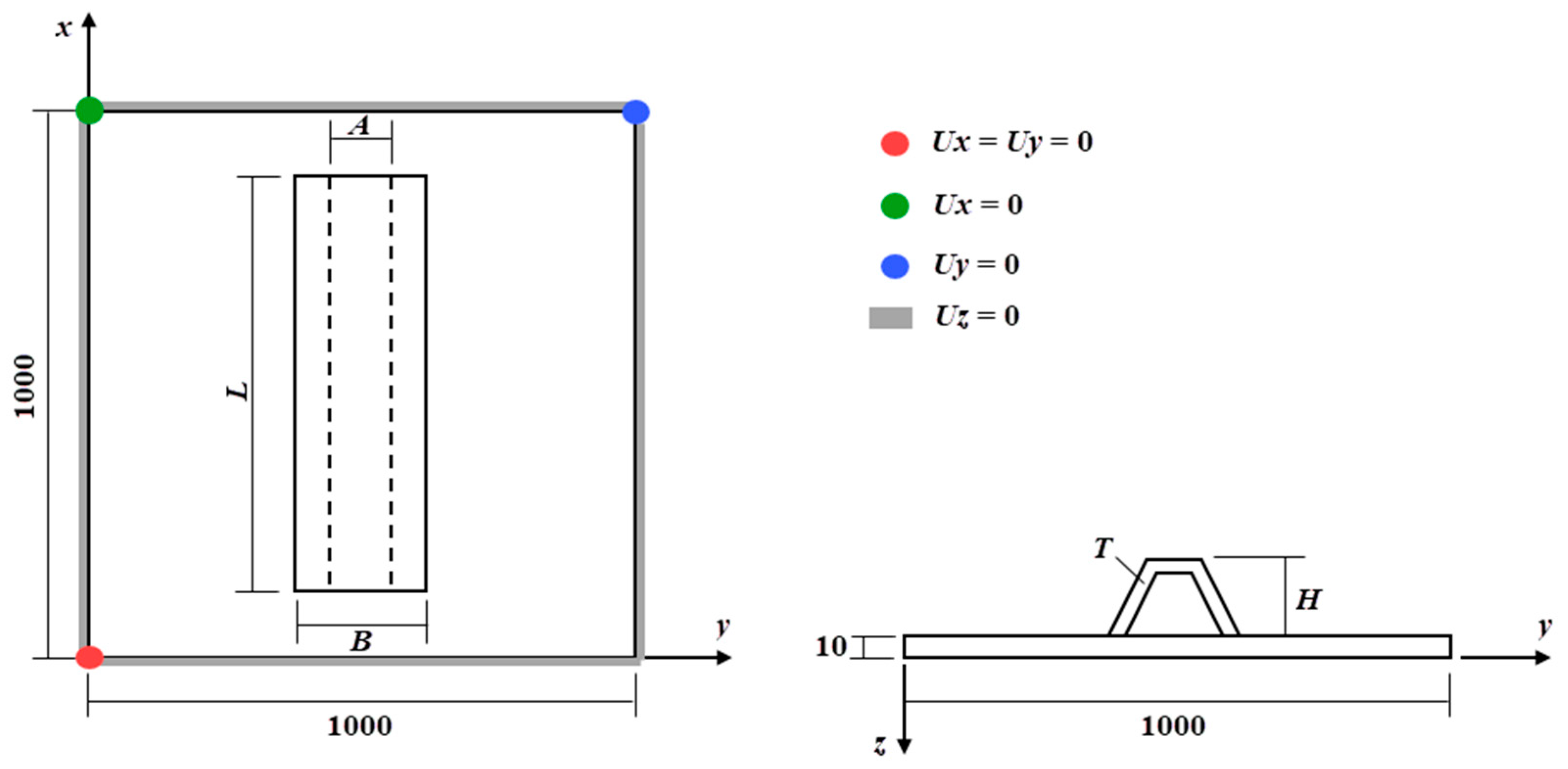
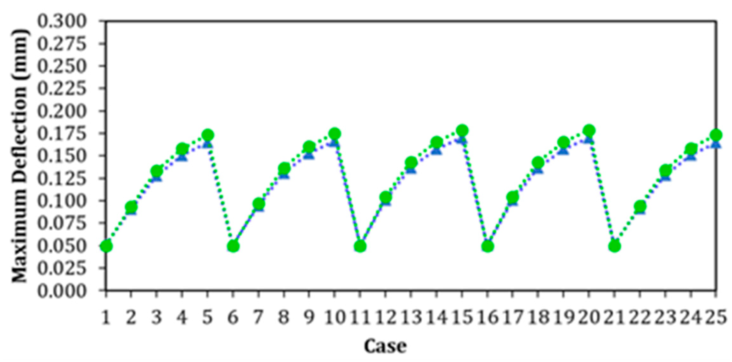


| Case | Thickness (T) | Shorter Base (A) | Longer Base (B) | Height (H) | Length (L) |
|---|---|---|---|---|---|
| 1 | 2 | 35 | 60 | 65 | 955.90 |
| 2 | 3 | 35 | 60 | 65 | 637.26 |
| 3 | 4 | 35 | 60 | 65 | 477.95 |
| 4 | 5 | 35 | 60 | 65 | 382.36 |
| 5 | 6 | 35 | 60 | 65 | 318.63 |
| 6 | 2 | 40 | 60 | 65 | 932.78 |
| 7 | 3 | 40 | 60 | 65 | 621.86 |
| 8 | 4 | 40 | 60 | 65 | 466.39 |
| 9 | 5 | 40 | 60 | 65 | 373.11 |
| 10 | 6 | 40 | 60 | 65 | 310.93 |
| 11 | 2 | 40 | 65 | 70 | 878.09 |
| 12 | 3 | 40 | 65 | 70 | 585.39 |
| 13 | 4 | 40 | 65 | 70 | 439.04 |
| 14 | 5 | 40 | 65 | 70 | 351.23 |
| 15 | 6 | 40 | 65 | 70 | 292.70 |
| 16 | 2 | 40 | 60 | 70 | 881.92 |
| 17 | 3 | 40 | 60 | 70 | 587.95 |
| 18 | 4 | 40 | 60 | 70 | 440.96 |
| 19 | 5 | 40 | 60 | 70 | 352.77 |
| 20 | 6 | 40 | 60 | 70 | 293.97 |
| 21 | 2 | 35 | 65 | 65 | 950.02 |
| 22 | 3 | 35 | 65 | 65 | 633.35 |
| 23 | 4 | 35 | 65 | 65 | 475.01 |
| 24 | 5 | 35 | 65 | 65 | 380.01 |
| 25 | 6 | 35 | 65 | 65 | 316.67 |
| Number of Hat-Stiffeners | hs (mm) | ts (mm) | (mm) | (mm) | RD (%) | RD (%) |
|---|---|---|---|---|---|---|
| 1 | 200 | 12.7 | 0.1647 | 0.1392 | −76.39 | −80.04 |
| 25 | 6.35 | 1.7712 | 1.7712 | 153.90 | 153.90 | |
| 2 | 225 | 8.00 | 0.0545 | 0.0466 | −92.19 | −93.32 |
| 25 | 6.35 | 0.5790 | 0.3262 | −17.00 | −53.24 | |
| 3 | 250 | 6.35 | 0.0252 | 0.0227 | −96.38 | −96.74 |
| 25 | 6.35 | 0.3169 | 0.3169 | −54.56 | −54.56 | |
| 4 | 125 | 8.00 | 0.0253 | 0.0253 | −96.38 | −96.38 |
| 25 | 6.35 | 0.2115 | 0.1882 | −69.68 | −73.03 | |
| 5 | 150 | 6.35 | 0.0211 | 0.0211 | −96.97 | −96.97 |
| 25 | 6.35 | 0.1771 | 0.1771 | −74.61 | −74.61 | |
| 6 | 175 | 4.75 | 0.0199 | 0.0166 | −97.15 | −97.62 |
| 25 | 6.35 | 0.1594 | 0.1562 | −77.15 | −77.61 | |
| 7 | 150 | 4.75 | 0.0220 | 0.0220 | −96.84 | −96.84 |
| 25 | 6.35 | 0.1525 | 0.1525 | −78.14 | −78.14 | |
| 8 | 125 | 4.75 | 0.0257 | 0.0245 | −96.31 | −96.49 |
| 25 | 6.35 | 0.1478 | 0.1473 | −78.82 | −78.88 | |
| 9 | 100 | 4.75 | 0.0315 | 0.0315 | −95.48 | −95.48 |
| 25 | 6.35 | 0.1466 | 0.1466 | −78.98 | −78.98 |
| Number of Hat-Stiffeners | hs (mm) | ts (mm) | (mm) | (mm) | RD (%) | RD (%) |
|---|---|---|---|---|---|---|
| 1 | 250 | 9.53 | 0.0958 | 0.0958 | −86.26 | −86.26 |
| 250 | 4.75 | 1.7735 | 1.7735 | 154.23 | 154.23 | |
| 2 | 150 | 6.35 | 0.1381 | 0.1266 | −80.20 | −81.84 |
| 25 | 6.35 | 0.5371 | 0.5371 | −23.01 | −23.01 | |
| 3 | 150 | 4.75 | 0.1244 | 0.1244 | −82.17 | −82.17 |
| 25 | 6.35 | 0.4497 | 0.4497 | −35.53 | −35.53 | |
| 4 | 125 | 4.75 | 0.1650 | 0.1650 | −76.34 | −76.34 |
| 25 | 9.53 | 0.6344 | 0.6345 | −9.06 | −9.04 | |
| 5 | 100 | 4.75 | 0.2259 | 0.2259 | −67.61 | −67.61 |
| 25 | 8.00 | 0.6014 | 0.6014 | −13.79 | −13.79 |
Disclaimer/Publisher’s Note: The statements, opinions and data contained in all publications are solely those of the individual author(s) and contributor(s) and not of MDPI and/or the editor(s). MDPI and/or the editor(s) disclaim responsibility for any injury to people or property resulting from any ideas, methods, instructions or products referred to in the content. |
© 2025 by the authors. Licensee MDPI, Basel, Switzerland. This article is an open access article distributed under the terms and conditions of the Creative Commons Attribution (CC BY) license (https://creativecommons.org/licenses/by/4.0/).
Share and Cite
Alves, M.A.; Rodrigues, E.M.; Rocha, L.A.O.; dos Santos, E.D.; Almeida, W.R.; Isoldi, L.A. Numerical and Geometrical Evaluation of Steel Plates with Transverse Hat-Stiffeners Under Bending. Metals 2025, 15, 647. https://doi.org/10.3390/met15060647
Alves MA, Rodrigues EM, Rocha LAO, dos Santos ED, Almeida WR, Isoldi LA. Numerical and Geometrical Evaluation of Steel Plates with Transverse Hat-Stiffeners Under Bending. Metals. 2025; 15(6):647. https://doi.org/10.3390/met15060647
Chicago/Turabian StyleAlves, Mariana Alvarenga, Eduarda Machado Rodrigues, Luiz Alberto Oliveira Rocha, Elizaldo Domingues dos Santos, William Ramires Almeida, and Liércio André Isoldi. 2025. "Numerical and Geometrical Evaluation of Steel Plates with Transverse Hat-Stiffeners Under Bending" Metals 15, no. 6: 647. https://doi.org/10.3390/met15060647
APA StyleAlves, M. A., Rodrigues, E. M., Rocha, L. A. O., dos Santos, E. D., Almeida, W. R., & Isoldi, L. A. (2025). Numerical and Geometrical Evaluation of Steel Plates with Transverse Hat-Stiffeners Under Bending. Metals, 15(6), 647. https://doi.org/10.3390/met15060647