Article

The Influence of Interface Morphology on the Mechanical Properties of Binary Laminated Metal Composites Fabricated by Hierarchical Roll-Bonding

School of Power and Mechanical Engineering, Wuhan University, Wuhan 430072, China
*
Author to whom correspondence should be addressed.
Metals 2025, 15(6), 580; https://doi.org/10.3390/met15060580
Submission received: 15 April 2025 / Revised: 16 May 2025 / Accepted: 22 May 2025 / Published: 23 May 2025
(This article belongs to the Special Issue Research Progress of Crystal in Metallic Materials)

Abstract

The interface morphology plays an important role in the mechanical properties of laminated metal composites (LMCs). In this study, binary LMCs with different crystallographic characteristics, namely Fe/Al (BCC/FCC), Ni/Al (FCC/FCC), and Mg/Al (HCP/FCC), were fabricated through the hierarchical roll-bonding process. The influence of interface morphology on the mechanical properties of the binary LMCs was investigated systematically. The results show that the strength–hardness coefficient (R) decreases with increasing interface morphology factor (α) for the LMCs, indicating that the strengthening effect of LMCs decreases with increased curvature of the interface. The experimental results reveal that α increases with the increase in rolling deformation (thickness reduction) for the LMCs, which is consistent with the finite element simulation results. The dependence of mechanical properties on interface morphology is mainly related to the microstructural inhomogeneity caused by localized deformation in the harder layer, including the formation of shear bands and variations in grain morphology, size, and orientation, which can lead to stress concentration in the necking zone.

Graphical Abstract

1. Introduction

Laminated metal composites (LMCs) integrate the superior properties of constituent metals by combining them in an alternating layered structure, enabling synergistic performance optimization [1,2]. This composite system not only preserves the inherent characteristics of each constituent metal but also further enhances comprehensive mechanical properties and functional features through interfacial effects and interlayer constraints [3,4]. The unique structural design allows the material to maintain lightweight characteristics while achieving high strength, high toughness, as well as excellent corrosion resistance and thermal stability [5,6,7,8,9]. Consequently, LMCs demonstrate broad application prospects in aerospace, transportation, energy equipment, and other fields.
The deformation-based fabrication of LMCs enables metallurgical bonding between dissimilar materials through plastic deformation, which promotes intimate contact and interfacial diffusion, thereby achieving a synergistic enhancement of the material properties [10,11,12,13]. Roll-bonding has been one of the most widely used and efficient methods for fabricating laminated composites [14,15,16]. Numerous binary systems, such as Ti/Al [17,18], Al/Cu [19,20], Mg/Al [14,21], Ni/Cu [22], Cu/Nb [23], Ti/Cu [24,25], etc., have been extensively studied based on roll-bonding fabrication, where process optimization and interface regulation have been found to play vital roles in enhancing the performance.
During the roll-bonding process of LMCs, microstructural evolution generally follows two distinct patterns [26]. The first mode maintains layer continuity while uniformly reducing the thickness of each constituent in accordance with the overall macroscopic strain. The second mode involves loss of layer continuity due to necking and fracture of harder constituent layers. In the latter case, the disparity in flow characteristics between components leads to localized necking and subsequent rupture of harder layers [26,27,28], which results in the inability to maintain a flat interface morphology. Plastic instability and fracture phenomena during roll-bonding are two critical limiting factors that govern the manufacturing process of metal laminates.
The plastic instability of harder phases is influenced by multiple factors, including material properties, processing conditions, and geometric parameters—specifically layer thickness, reduction ratio, temperature, lubrication conditions, roll diameter, and rolling speed [29,30]. Significant progress has been made in understanding the relationship between harder-layer necking and hardness matching, layer thickness, and the intrinsic deformability of materials [28,31]. Rahdari et al. [28] conducted systematic experimental and simulation studies on roll-bonded Ni-Al, Cu-Al, and brass-Al LMCs, revealing the effects of layer thickness, hardness difference between soft and hard phases, and layer sequence on necking. Miyajima et al. [31] proposed that reducing the strength difference between soft and hard layers, along with maintaining a lower work-hardening rate in hard layers compared to soft layers during accumulative roll-bonding (ARB) processing, can effectively alleviate necking in Al/Cu multilayer composites. However, current research primarily focuses on optimizing process parameters to achieve high strength and toughness, while the influence of interface morphology evolution during roll-bonding on mechanical performance remains insufficiently explored.
In this study, a series of binary LMCs, namely Fe/Al (BCC/FCC), Ni/Al (FCC/FCC), and Mg/Al (HCP/FCC), with distinct interface morphologies were fabricated via the hierarchical roll-bonding process. The binary LMCs contain two main constitutive phases: Al (FCC) as the softer phase and Fe (BCC), Ni (FCC), and Mg (HCP) as the harder phases with different crystal structures. The microstructure and mechanical properties of the LMCs were characterized. Specifically, the influence of interface morphology on the mechanical properties of the LMCs were investigated systematically.

2. Materials and Methods
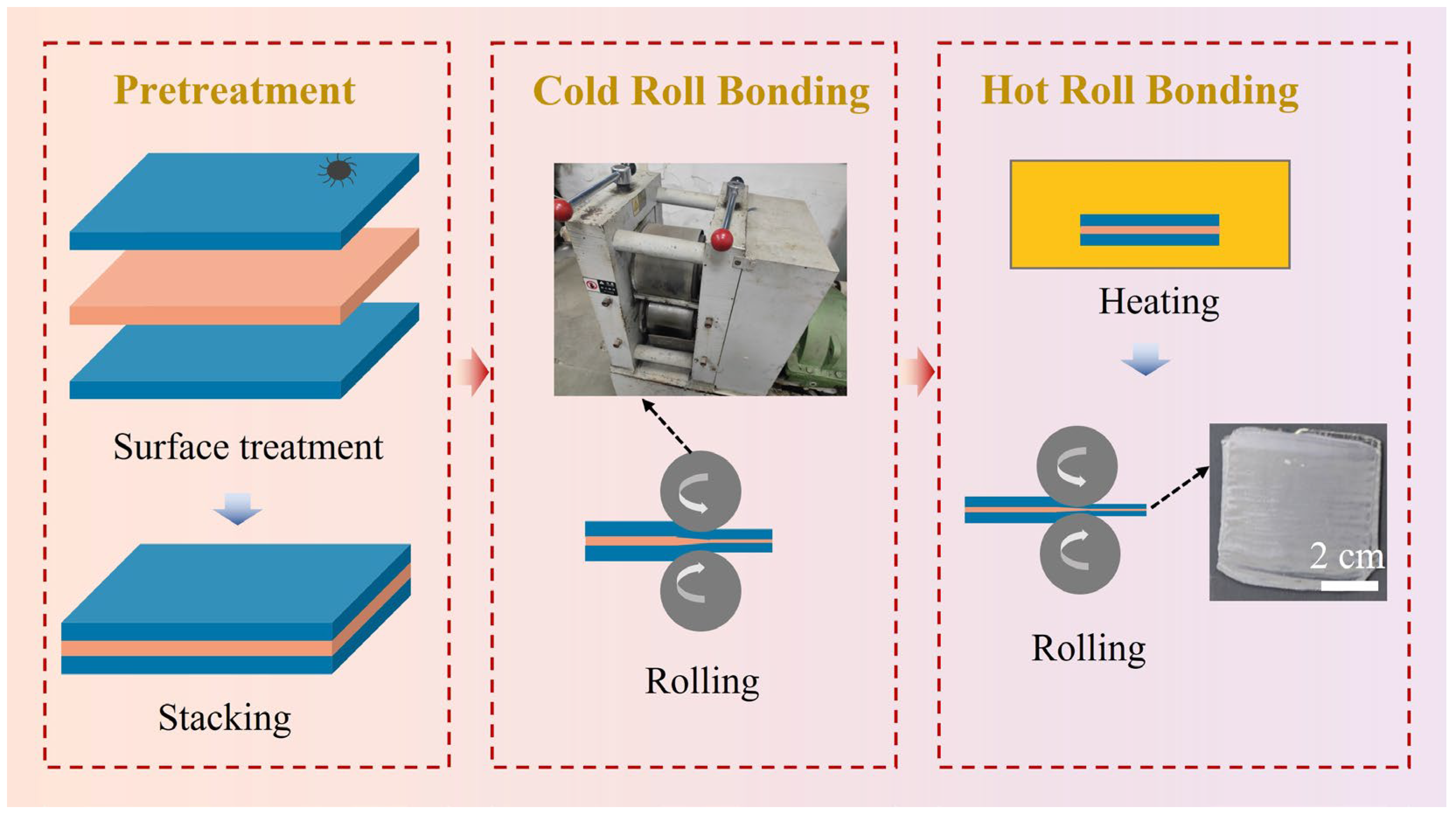
2.1. Fabrication

Three typical metals with different crystal structures, pure Fe (BCC structure), pure Ni (FCC structure), and AZ31B Mg alloy (HCP structure), were selected as the harder layer metals, while pure Al (FCC structure) was used as the softer layer metal to fabricate binary LMCs. The hierarchical roll-bonding process, mainly including cold roll-bonding and hot roll-bonding, is shown in Figure 1. This process was employed to prepare a series of three-layer composites with different thickness reductions. The sample numbering and processing parameters are shown in Table 1.
The raw metal plates (Al, Fe, Ni, and AZ31B Mg alloy) were cut into uniform dimensions (50 mm in length × 20 mm in width) using a wire electrical discharge machine (DK7735, Taizhou, China), and the thickness of the plates used was 0.5–1.5 mm. The surfaces of the metal plates were polished with an electric wire brush and thoroughly cleaned. The samples were stacked in order according to the constituent metals and then subjected to room-temperature rolling using a rolling mill (ZX-RZJ20150L, Dongguan, China). Subsequently, the room-temperature-rolled samples were placed in a muffle furnace (SX2-2.5-10, Shanghai, China) and held at corresponding temperatures for specific durations before hot rolling. The hot rolling temperatures for Fe/Al, Ni/Al, and Mg/Al LMCs were 600 °C, 600 °C, and 400 °C, respectively, with holding times of 30 min, 30 min, and 10 min.

2.2. Characterization

The microstructure of the LMCs was characterized using an optical microscope (OM, Carl Zeiss Axio Lab.A1, Oberkochen, Germany) and a field-emission scanning electron microscope (SEM, TESCAN CLARA, Brno, Czech Republic) equipped with an energy-dispersive X-ray spectroscopy (EDS, Oxford, UK) and an electron backscatter diffraction (EBSD, Oxford, UK). The samples for OM, SEM, and EBSD observations were prepared by mechanical grinding and polishing with 50 nm SiO2 suspension, with the observation plane being the RD (rolling direction) ND (normal direction) planes.
The microhardness of the samples was measured with a load of 50 g and a duration of 10 s by using an HXS-1000A microhardness tester (Laizhou, China). All reported data represent the average of at least five measurements. The tensile tests were conducted at room temperature using the MTS E45 universal testing machine (Shandong, China), with a displacement rate of 0.5 mm/min and the loading direction parallel to the RD. The tensile samples had a gauge length of 6 mm.

2.3. Finite Element Simulation

A commercial finite element software (ABAQUS 2022) was employed to numerically simulate the interlayer continuity during the cold roll-bonding process. The simulation was conducted under three-dimensional dynamic/explicit and plane strain conditions. Both the Al and Fe layers were assumed to be isotropic von Mises materials, and the initial dimensions of each plate were 50L × 20W × 1T mm. The inner and outer layers were treated as elastic–perfectly plastic materials. The mechanical properties of these materials, as listed in Table 2, were used for the simulation. Based on the engineering stress–strain curves of raw Fe and Al plates obtained from the tensile tests, the true stress–strain curves were converted to derive the material’s true mechanical behavior data. The discretized data points were then input into ABAQUS to simulate the plastic deformation response during the roll-bonding process. A tie constraint was applied to bond the ends of the strips at the interface between the two layers, preventing any relative sliding. To ensure no relative sliding occurs, the friction coefficients between the roller and sheet and between adjacent sheets were respectively set as 0.3 and 0.6, which were chosen after multiple trials. Tangential contact was modeled using the penalty method, while normal contact was treated as hard contact. The roller rotated at a speed of 5 rad/s, and the sheet-feeding speed was set at 30 mm/s. The model employed C3D8R elements (eight-node linear hexahedral elements) for meshing each layer. The roller mesh size was 5 mm, while the sheet mesh sizes were determined to be 0.75 mm in plane and 0.1 mm in thickness through multiple simulations.

3. Results and Discussion

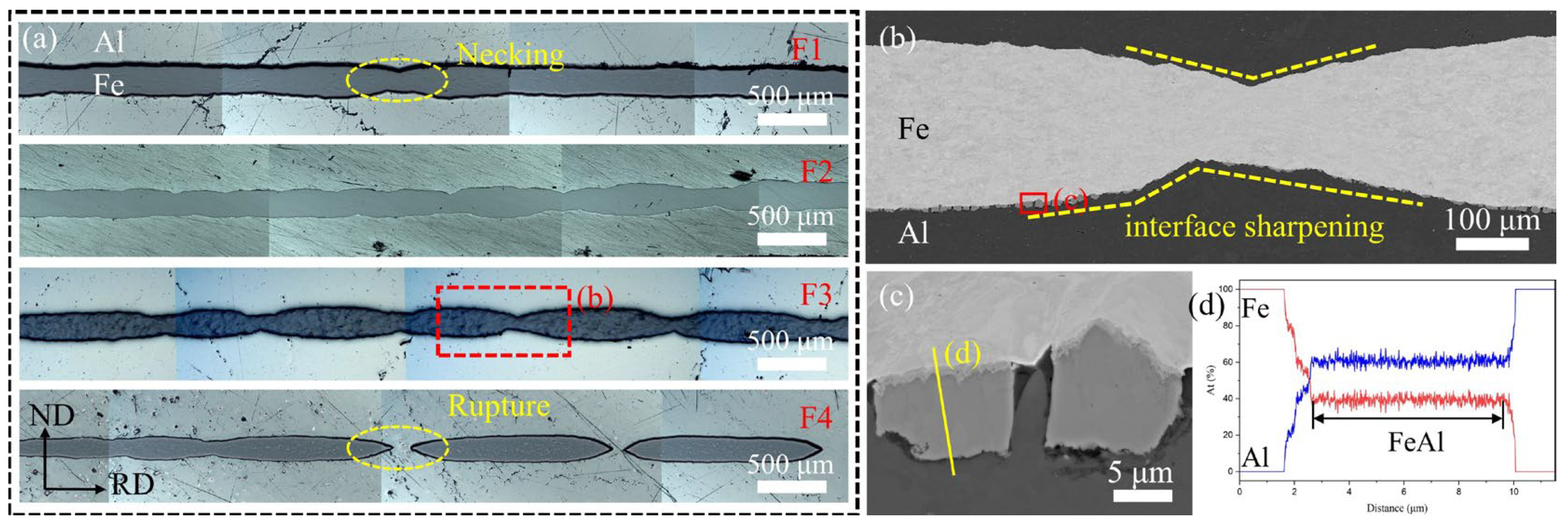
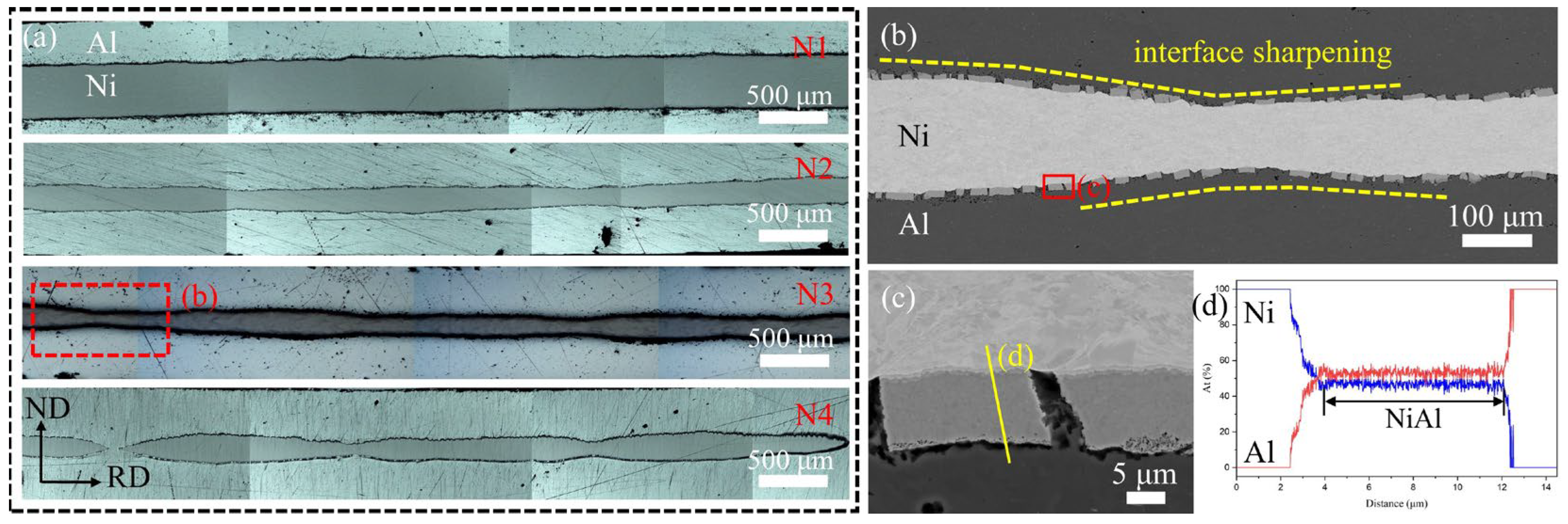
3.1. Interface Morphology of LMC Samples
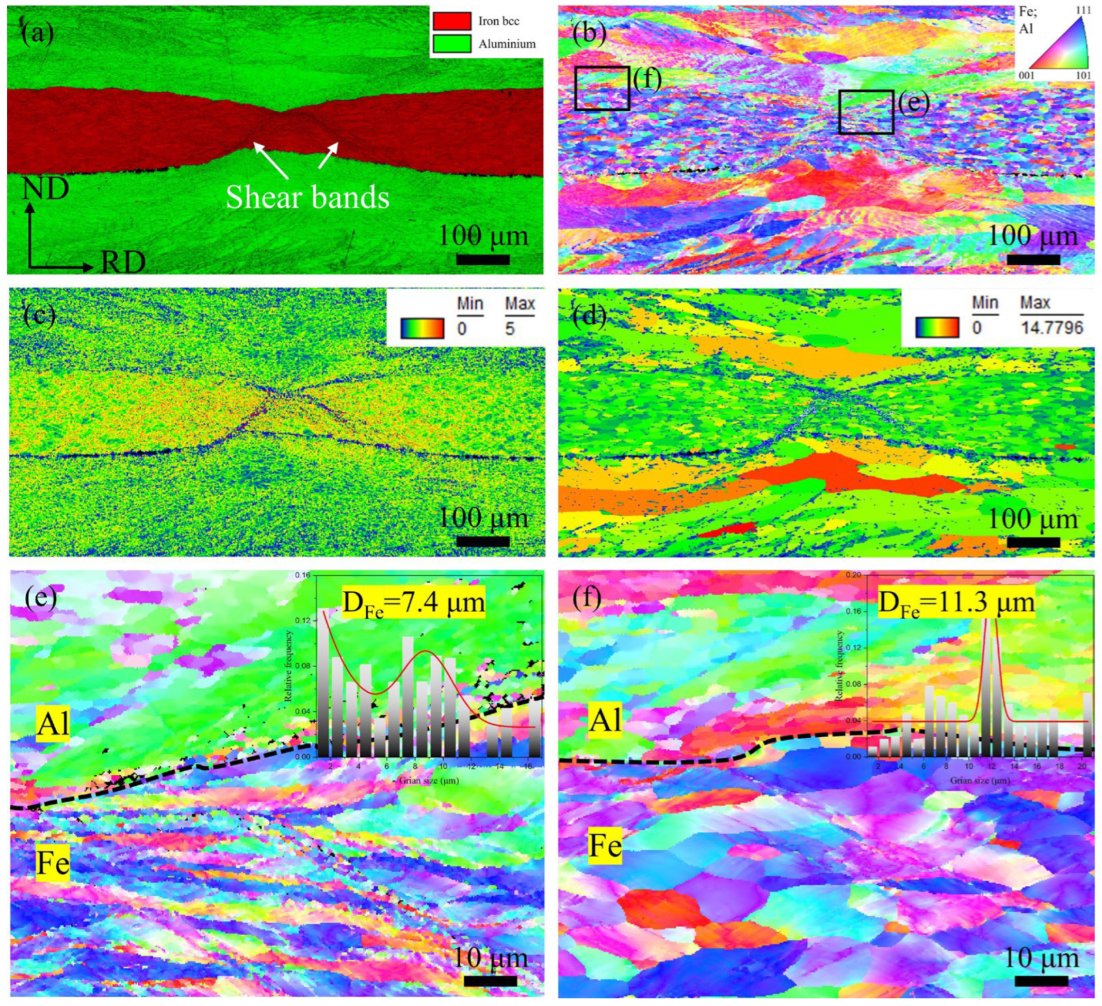
Figure 2 presents the microstructure images and EDS line scan results of Fe/Al LMCs in this study. Figure 2a displays the overall interfacial morphology of samples F1–F4. Among them, samples F1–F3 exhibit varying degrees of interfacial curvature, while sample F4 shows interfacial discontinuity. Comparing the reduction ratios of the Fe layer, sample F1, with the flattest interface and minimal necking, has the lowest rolling thickness reduction (60%), whereas sample F4, showing fractured layer, has the highest (71%). This suggests that interfacial morphological variation caused by Fe layer necking correlates closely with rolling thickness reduction. Figure 2b provides an SEM-BSE image of the necking region (the red dashed box in Figure 2a) in sample F3, revealing obvious interfacial fluctuations. The Fe-Al interface undergoes “interface sharpening” in this region, where the originally flat interface develops reduced curvature radii, forming geometric abruptness. Figure 2c shows a magnified Fe-Al interface with ~7 μm thick discrete interfacial reaction products. EDS line scans (Figure 2d) confirm these as FeAl intermetallic. The discrete distribution results from the fragmentation of the FeAl phase during hot rolling due to their limited deformability. Similar observations were reported for Mg/Al LMCs [32,33], where interfacial phases can enhance interfacial bonding via pinning effects. Here, the FeAl phase formed at 600 °C for 30 min exhibit optimal dimensions, validating the suitability of these rolling parameters for Fe/Al LMCs.
Figure 3 shows the microstructure images and EDS line scan results of Ni/Al LMCs. Figure 3a displays the overall interfacial morphology of samples N1–N4. Sample N1 with lower deformation maintains flat interfaces, while samples N2–N4 exhibit varying degrees of interfacial curvature. Similar to Fe/Al LMCs, the degree of morphological change in the harder layer correlates with thickness reduction. Figure 3b presents an SEM-BSE image of the necking region (marked by the red dashed box in Figure 3a) in sample N3. Compared to sample F3, the Ni-Al interface shows lighter “interface sharpening” with larger curvature radii. The magnified interface image (Figure 3c) reveals ~10 μm thick interfacial reaction products, primarily composed of NiAl phase compounds (Figure 3d).

3.2. Microstructure

EBSD characterizations were employed for further characterization of the microstructural characteristics of the LMCs with evident interface curvature to provide insights into the correlation between interface morphology and microstructure heterogeneities of the LMCs.
Figure 4 shows the EBSD images of sample F3. Figure 4a presents the Image Quality (IQ) map overlaid with phase distribution, where two distinct shear bands oriented at ~45° to the rolling direction are observed near the necking points of the Fe phase, extending through the entire Fe layer. The formation of shear bands is characteristic of strain localization [29,34,35], which occurred during the roll-bonding deformation of sample F3. During roll-bonding deformation, the accumulation of dislocations at interfaces promotes strain localization, which can lead to the transformation of the initially uniform plastic deformation to the non-uniform mode. Such inhomogeneous deformation can induce severe localization of strain/stress, leading to the formation of localized deformation bands [36,37,38]. This phenomenon also accounts for the sudden drop observed in the tensile curve of sample F3, as will be shown later, where stress concentration at the shear bands during tensile testing caused premature failure and fracture of the specimen, resulting in lower strength and elongation [39]. As shown in Figure 4b, the grain structures of the Al and Fe layers show distinct heterogeneity with more refined grains around the curved interface region, indicating the high localized strain there.
Figure 4c displays the Kernel Average Misorientation (KAM) map, showing that the KAM values in the Fe layer are markedly higher than those in the Al layer. Moreover, the KAM values near the necking points in the Fe layer are substantially elevated compared to the non-necking regions, indicating severe dislocation accumulation and localized plastic strain in these areas. The higher KAM values in the Fe layer compared to the Al layer stem from its lower stacking fault energy, which suppresses dynamic recovery and leads to continuous accumulation of geometrically necessary dislocations (GNDs) [40]. In contrast, the Al layer accommodates plastic deformation more effectively through mechanisms such as dislocation slip and dynamic recrystallization. The further increase in KAM values near necking points highlights strain concentration effects caused by plastic instability. This region exhibits significant work hardening due to intense dislocation multiplication and entanglement but may also serve as potential sites for microdamage nucleation. Such a heterogeneous deformation behavior underscores the critical role of interfacial strain partitioning in Al-Fe-Al laminated composites. The limited strain accommodation capacity of the Fe layer may be a key factor influencing the overall mechanical performance of the material.
Figure 4d presents the Grain Orientation Spread (GOS) map, revealing that the GOS value in the Al layer is much higher than that in the Fe layer. Notably, the Al grains adjacent to the necking points of the Fe layer exhibit the highest GOS value. This phenomenon can be attributed to the following mechanisms: During cold rolling, the Al layers, with lower yield strength, undergo plastic deformation first, resulting in elongated grains and high dislocation density structures. In subsequent hot rolling, although the 600 °C annealing promotes partial dynamic recovery in the Al layer, the combined effects of hot rolling deformation and constraint from the Fe layer prevent complete recrystallization of Al grains, leading to retained orientation gradients (manifested as higher GOS values). Particularly near the necking regions of the Fe layer, Al grains experience three synergistic effects: (i) The dislocation accumulated during cold rolling pre-deformation are not fully eliminated during hot rolling; (ii) the localized large strains caused by necking force Al grains to accommodate deformation through heterogeneous slip; and (iii) the high-strength constraint from the Fe layer inhibits stress relaxation in Al grains, collectively resulting in the observed higher GOS distribution. In contrast, the Fe layer demonstrates a relatively lower GOS value due to its higher recrystallization temperature (making complete recrystallization difficult at 600 °C). During hot rolling, the Fe layer primarily undergoes dislocation rearrangement rather than significant lattice rotation, accounting for its overall lower GOS values.
Figure 4e,f further illustrate the microstructural morphology of the sample F3 in both the necked and non-necked regions. Notably, the Fe grains in the necked zone exhibit significant refinement and elongation. A statistical analysis of grain size reveals that the necked region has smaller grains (~7.4 μm) compared to the non-necked zone (~11.3 μm). Additionally, the grain orientation near the shear bands deviates from the rolling direction (TD), instead aligning with the shear direction. This reorientation indicates that the material undergoes intense shear deformation during necking, causing localized grain rotation to accommodate plastic flow. Meanwhile, the Al layer in the necked zone displays more severe grain distortion, consistent with the GOS analysis results.
Figure 5 presents the EBSD microstructural characterization of sample N3. Figure 5a shows the IQ map overlaid with phase distribution. Unlike sample F3, the shear band traces are less pronounced and do not penetrate the entire Ni layer, which may be attributed to the better deformability of Ni compared to Fe. Similar to the Fe/Al composite (Figure 4), the Ni layer exhibits a higher KAM value near necking regions (Figure 5c), while the Al layer shows a higher GOS value (Figure 5d). Comparing the grain morphology between the necked (Figure 5e) and non-necked regions (Figure 5f), the Ni grains in the necked zone appear elongated and reoriented, deviating from the TD direction. A statistical analysis reveals finer grain sizes in the necked region (~8.9 μm) than that in the non-necked area (~10.1 μm).
Through EBSD characterization of the F3 and N3 samples, we observed that in addition to interfacial morphological variation, the necking zones also underwent significant microstructural evolution. In the harder-phase layers (Fe/Ni), shear bands formed near the necking points, causing grain rotation along the strain localization bands. These rotated grains no longer remained parallel to the rolling direction (which was also the tensile direction during testing). Since the rolling direction originally exhibited certain anisotropic characteristics, the presence of shear bands disrupted the initially well-aligned crystallographic orientation. During subsequent tensile testing, these rotated grains exhibited markedly different deformation behavior compared to the surrounding grains, leading to stress gradients and localized stress concentrations at the grain boundaries. Furthermore, the necking zones displayed pronounced grain refinement and elongation, creating a stark microstructural heterogeneity compared to the non-necked regions. This inhomogeneity adversely affects stress distribution and uniform plastic deformation, significantly degrading the tensile properties of the LMCs.

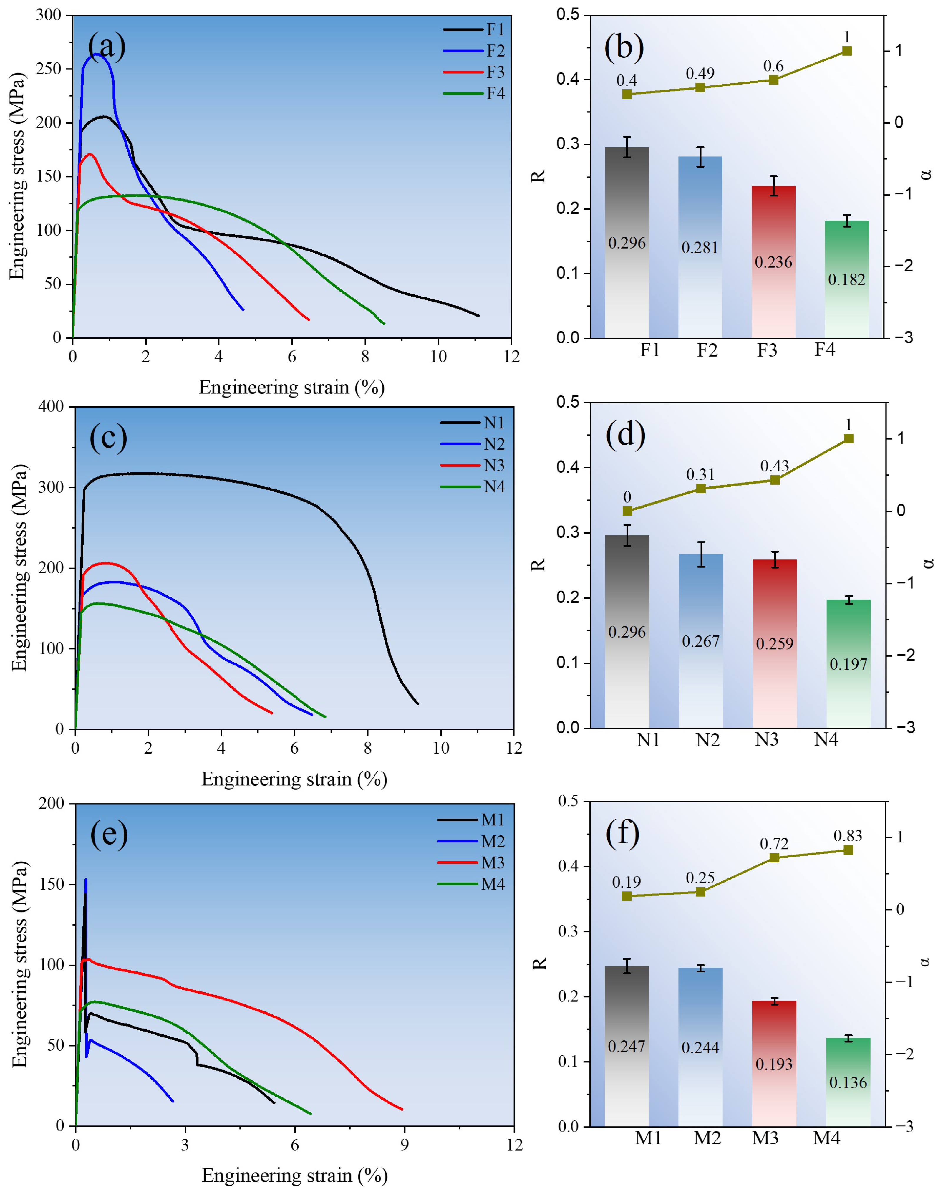
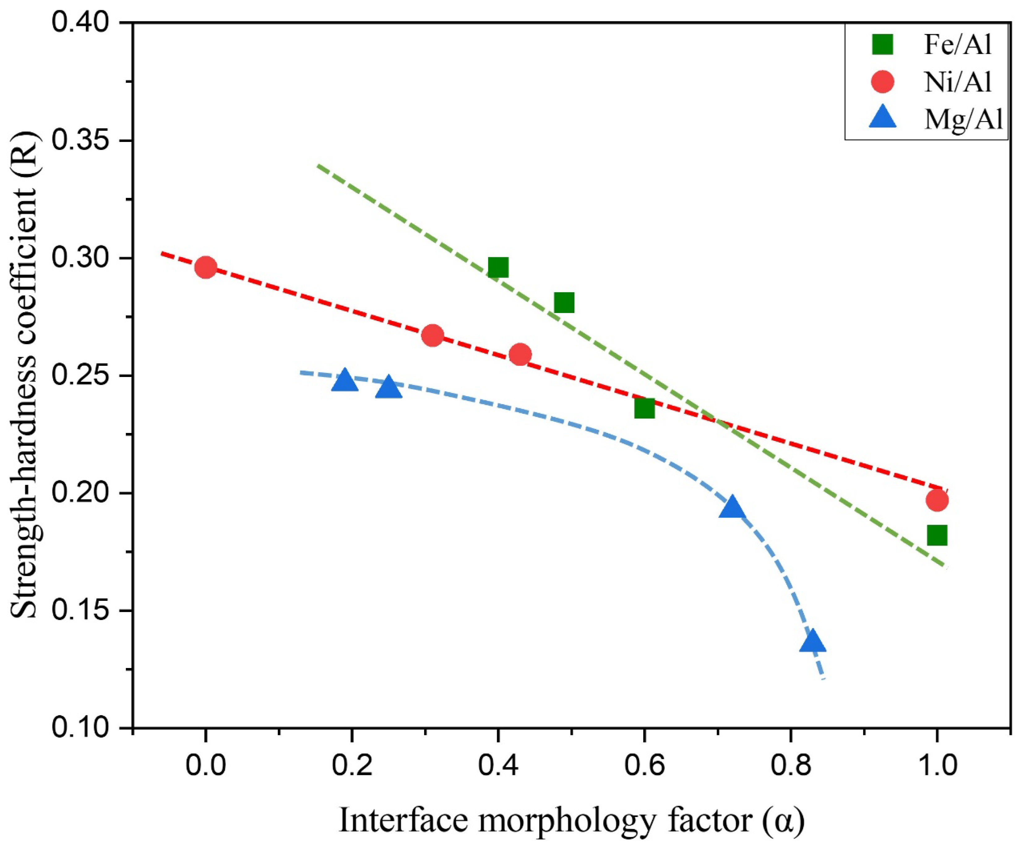
3.3. Relationship Between Interface Morphology and Mechanical Properties

The mentioned LMCs experienced varying degrees of necking during the rolling process. To quantify the interfacial morphological alterations induced by necking and thereby establish the relationship between the interface morphology and mechanical properties, the interface morphology factor α was introduced as follows [41]:
α = d m a x d m i n d m a x
where dmax and dmin represent the maximum and minimum thicknesses of the necked harder layer, respectively. When the interface morphology is perfectly flat, α = 0. As the interface becomes curved due to necking of the harder layer, the α value gradually increases. When the hard layer completely fractures, α = 1 for dmin = 0.
As one of the most characteristic material properties, hardness is typically defined as the ratio of indentation load to the residual indentation surface or projected area [42]. Both hardness and strength reflect a material’s resistance to deformation and failure. Therefore, in work-hardened metals and certain bulk metallic glass materials, the Vickers hardness (MPa) and ultimate tensile strength (σUTS) often follow the empirical threefold relationship:
H V 3 σ U T S
Although the relationship between hardness and strength is influenced by factors such as material type, grain coarsening, and defects, the hardness-to-strength ratio should remain relatively stable for materials within the same system prepared under identical processing conditions. Therefore, this study introduces the average hardness (Have.) based on the rule of mixtures and the strength–hardness coefficient (R) to characterize how interfacial morphology and layer count affect the strength of laminated composites. The average hardness (Have.) is expressed by
H a v e . = H A V A + H B V B
where HA and HB represent the micro-Vickers hardness of constituents A and B, respectively, and VA and VB denote the volume fractions of constituents A and B, respectively.
The strength–hardness coefficient (R) is expressed by Equation (4):
R = σ U T S H a v e .
The values of α and R for different LMCs were calculated according to Equation (1) and Equations (2)–(4), respectively. Figure 6 presents the tensile engineering stress–strain curves of Fe/Al, Ni/Al, and Mg/Al LMCs under room-temperature, along with the statistical relationship between the interfacial morphology factor α and strength–hardness coefficient R. Through a comparative analysis of all samples, a significant negative correlation between α and R is observed: as the interfacial morphology factor α increases, the strength–hardness coefficient R demonstrates a decreasing trend. This phenomenon indicates that intensified interfacial morphological changes significantly compromise the mechanical performance of the composites, manifesting specifically as reduced strength metrics. In other words, within LMCs, interfacial morphological alterations induced by necking deformation in harder layers degrade the overall load-bearing capacity of the material, resulting in experimental strength values that fall below the theoretically predicted strength based on constituent hardness, according to Equation (2), from which the R values are about 0.33 in LMCs.
Table 3 presents the yield strength (σYS), ultimate tensile strength (σUTS), and uniform elongation (δ) of each specimen under room-temperature tensile tests, according to Figure 6a,c,e. The yield strength and ultimate tensile strength exhibit consistent trends. In terms of δ, for the Fe/Al and Ni/Al samples that did not fracture (0 ≤ α < 1), δ gradually decreases with increasing α, indicating that changes in interfacial morphology weaken the work-hardening capacity of these Fe/Al and Ni/Al LMCs. However, the completely fractured sample (F4, α = 1) shows a relatively high δ value, suggesting that when the harder-phase components are discontinuously distributed in the softer matrix, they can positively enhance the material’s work-hardening capacity. In the Mg/Al LMCs, all samples demonstrate uniformly low levels of δ, exhibiting an effect completely opposite to that observed in the Fe/Al and Ni/Al LMCs. When the interfacial morphology shows little changes (low α), the tensile curves of Mg/Al LMCs are disrupted even during the elastic stage, resulting in the relatively low δ. In contrast, at higher α values, the δ slightly improves. This phenomenon may be attributed to the inherently low deformability of the Mg layers, which promotes the work-hardening capacity, similar to that observed in the F4 LMC sample where the Fe layers underwent complete fracture.
From the perspective of fracture elongation, the N1 sample with flat interfaces (α = 0) demonstrates significantly superior plastic deformation capability compared to other samples (Figure 6c). A systematic observation of the engineering stress–strain curves for other samples reveals a common characteristic: a sudden, dramatic stress drop occurs at relatively low levels of both strength and elongation. This phenomenon exerts a markedly negative impact on the overall mechanical performance of the composites, with its primary mechanism attributable to fracture failure of the harder-phase components.
In summary, the interface morphology plays a crucial role in the mechanical performance of composite materials. In roll-bonded LMCs, a smooth and intact interface contributes to enhancing the strength–toughness balance of the material. The deterioration of interface morphology exerts a significantly more detrimental effect than the mere compositional imbalance between constituent layers, and this adverse impact intensifies with the degree of interfacial damage.
Figure 7 shows the relationship between R and α for all LMC samples based on the data from Figure 6. Fitting curves were established for the three material systems according to their R and α values. The results show that the R-α relationship in Fe/Al and Ni/Al LMCs basically follows a linear pattern, with R decreasing at an almost constant rate as α increases. The decrease rate of R of Ni/Al LMCs is slower than that of Fe/Al LMCs, indicating that the tensile strength of Ni/Al LMCs is less sensitive to morphological variations. For Mg/Al LMCs, at low α values, the curve’s slope is comparable to that of Ni/Al LMCs, but at high α values, R declines more rapidly. This suggests that once the morphology of Mg/Al LMCs deteriorates beyond a certain threshold, their strength-bearing capacity drops drastically.

3.4. Finite Element Analysis

Based on the thickness reduction in Table 1 and the α-value statistics in Figure 6, we observed an overall increasing trend in the α-values of LMCs with greater thickness reduction (albeit not in a completely linear relationship). Since the deformation amounts in Table 1 represent the cumulative cold-rolling deformation after multiple passes (~3–4) through the rolling mill as well as the hot-rolling deformation, they may not directly and intuitively reflect the relationship between deformation amount and interface morphology. Finite element simulations were further performed on the Fe/Al LMCs. Figure 8 shows the microstructure and equivalent Mises stress distribution from finite element simulations of Fe/Al LMCs with different rolling deformations of 30%, 35%, and 40%, along with the α values calculated using Equation (1) (0, 0.39, and 0.53, respectively). As the deformation increases, the α value of the composites increases, indicating a greater degree of necking, which is consistent with the experimental results. Additionally, the Mises stress is highly concentrated in the Fe layer, which is the result of local plastic instability due to the insufficient plastic deformation capacity of the Fe layer, leading to stress concentration and necking. The finite element results indicate that the interfacial morphology factor α increases with greater thickness reduction, which is consistent with the experimental observations.

4. Conclusions

In this study, a series of binary laminated metal composites, including Fe/Al (BCC/FCC), Ni/Al (FCC/FCC), and Mg/Al (HCP/FCC), were prepared by the hierarchical roll-bonding process. The microstructure and mechanical properties of the LMCs were studied, with an emphasis on the specific effect of interfacial morphology on the mechanical properties. The interfacial morphology was found to have an evident effect on the mechanical properties of LMCs. The strength–hardness coefficient R decreases with increasing interface morphology factor α, indicating that the strengthening effect of composites decreases with decreased interface flatness. It is found that α increases with increasing rolling deformation, which is also validated by finite element simulations. The microstructural analysis reveals remarkable microstructure inhomogeneity between the necked and non-necked zones in samples with high α. In the necked zones, the formation of shear bands coupled with alterations in grain morphology, size, and orientation result in elevated KAM and GOS values within the harder phases. This can lead to significant stress concentration, making the necked zones prone to serve as crack nucleation sites and even causing premature failure of the specimens.

Author Contributions

Conceptualization, Q.M.; methodology, Y.T.; software, X.L., Y.T. and Q.M.; formal analysis, Y.T. and Q.M.; investigation, Y.T. and X.L.; resources, Y.T.; data curation, Y.T.; writing—original draft preparation, Y.T.; writing—review and editing, Q.M.; visualization, Y.T.; supervision, Q.M.; project administration, Q.M.; funding acquisition, Q.M. All authors have read and agreed to the published version of the manuscript.

Funding

This work was supported by the National Natural Science Foundation of China (grant 52175358). Support from the Open Fund of the Core Facility of Wuhan University.

Data Availability Statement

The original contributions presented in this study are included in the article. Further inquiries can be directed to the corresponding author.

Acknowledgments

We thank Wenting Fan from the Core Facility of Wuhan University for assistance with the SEM/EBSD measurements.

Conflicts of Interest

The authors declare no conflicts of interest.

References

  1. Konieczny, M. Microstructural characterisation and mechanical response of laminated Ni-intermetallic composites synthesized using Ni sheets and Al foils. Mater. Charact. 2012, 70, 117–124. [Google Scholar] [CrossRef]
  2. Li, T.; Shao, B.; Gao, C.; Tang, W.; Liu, J.; Zong, Y.; Shan, D.; Guo, B. Study on unsteady rolling cooperative deformation and interface behavior of Ti2AlNb/7075Al laminated metal composites. Compos. Part B 2025, 300, 112458. [Google Scholar] [CrossRef]
  3. Tang, X.; Peng, Q.; Long, J.; Wang, X.; Lin, Y.; Deng, L.; Jin, J.; Gong, P.; Zhang, M.; Lee, M.-G. Recent progress on plastic forming of laminated metal composites: Processes, heterogeneous deformation, and interfacial regulation. J. Mater. Sci. Technol. 2025, 229, 67–91. [Google Scholar] [CrossRef]
  4. Gao, K.; Zhang, X.; Liu, B.; He, J.; Feng, J.; Ji, P.; Fang, W.; Yin, F. The Deformation Characteristics, Fracture Behavior and Strengthening-Toughening Mechanisms of Laminated Metal Composites: A Review. Metals 2019, 10, 1–19. [Google Scholar] [CrossRef]
  5. Huang, M.; Xu, C.; Fan, G.; Maawad, E.; Gan, W.; Geng, L.; Lin, F.; Tang, G.; Wu, H.; Du, Y.; et al. Role of layered structure in ductility improvement of layered Ti-Al metal composite. Acta Mater. 2018, 153, 235–249. [Google Scholar] [CrossRef]
  6. Luo, Z.A.; Mao, L.Y.; Huang, C.; Zhou, H.Y.; Wang, M.K. A strategy for simultaneously enhancing mechanical strength and hydrogen embrittlement resistance: Exceptional performance of laminated metal composite in hydrogen environments. Mater. Des. 2024, 237, 112549. [Google Scholar] [CrossRef]
  7. Wang, Z.; Bian, Y.; Yang, M.; Ma, R.; Fan, Y.; Du, A.; Zhao, X.; Cao, X. Investigation of coordinated behavior of deformation at the interface of Cu–Al laminated composite. J. Mater. Res. Technol. 2023, 24, 6545–6557. [Google Scholar] [CrossRef]
  8. Wadsworth, J.; Lesuer, D.R. Ancient and modern laminated composites—From the Great Pyramid of Gizeh to Y2K. Mater. Charact. 2000, 45, 289–313. [Google Scholar] [CrossRef]
  9. Mozaffari, A.; Danesh Manesh, H.; Janghorban, K. Evaluation of mechanical properties and structure of multilayered Al/Ni composites produced by accumulative roll bonding (ARB) process. J. Alloys Compd. 2010, 489, 103–109. [Google Scholar] [CrossRef]
  10. Perepezko, J.H.; Hebert, R.J.; Hamann, J. Deformation-induced alloying and reactions in nanostructured multilayers. J. Alloys Compd. 2007, 434–435, 459–462. [Google Scholar] [CrossRef]
  11. Sun, Y.; Liu, X.; Wang, W.; Yang, Y.; Zhang, W. Diffusion mechanism of immiscible Fe-Mg system induced by high-density defects at the steel/Mg composite interface. J. Mater. Sci. Technol. 2023, 144, 150–160. [Google Scholar] [CrossRef]
  12. Wang, W.; Wang, H.; Liu, X.; Liu, Z. Interface evolution and strengthening of two-step roll bonded copper/aluminum clad composites. Mater. Charact. 2023, 199, 112778. [Google Scholar] [CrossRef]
  13. Bay, N. Cold Welding: Part 1. Characteristics, Bonding Mechanisms. Bond. Strength 1986, 18, 369–372. [Google Scholar]
  14. Yu, Z.; Wang, T.; Liu, C.; Ma, Y.; Liu, W. Investigation on microstructure, mechanical properties and fracture mechanism of Mg/Al laminated composites. Mater. Sci. Eng. A. 2022, 848, 143410. [Google Scholar] [CrossRef]
  15. Gao, H.; Kong, C.; Yu, H. Lightweight metal laminated plates produced via (hot, cold and cryogenic) roll bonding: A review. Trans. Nonferrous Met. Soc. China 2023, 33, 337–356. [Google Scholar] [CrossRef]
  16. Wright, P.K.; Snow, D.A.; Tay, C.K. Interfacial conditions and bond strength in cold pressure welding by rolling. Met. Sci. J. 1978, 5, 24–31. [Google Scholar] [CrossRef]
  17. Gao, B.X.; Hao, Y.C.; Yu, C.; Wu, Y.H.; Xiao, H. Study on temperature control and bonding properties of Ti/Al composite plates rolled by differential temperature rolling with mobile induction heating. J. Manuf. Process. 2025, 134, 348–359. [Google Scholar] [CrossRef]
  18. Guo, S.; Wang, F.; Wang, Y.; Xie, G. Microstructural evolution and properties of Ti/Al clad plate fabricated by vacuum rolling and heat treatment. Mater. Sci. Eng. A. 2023, 882, 145445. [Google Scholar] [CrossRef]
  19. Li, S.; Luo, C.; Liu, Z.; Zhao, J.; Han, J.; Wang, T. Interface characteristics and mechanical behavior of Cu/Al clad plate produced by the corrugated rolling technique. J. Manuf. Process. 2020, 60, 75–85. [Google Scholar] [CrossRef]
  20. Cai, H.S.; Wang, Q.D.; Zhang, N.N.; Ebrahimi, M.; Zhao, Y.C.; Liu, L.; Guo, F. Shear behavior of Cu/Al/Cu trilayered composites prepared by high-temperature oxygen-free rolling. J. Alloys Compd. 2024, 1004, 175857. [Google Scholar] [CrossRef]
  21. Liu, T.; Song, B.; Huang, G.; Jiang, X.; Guo, S.; Zheng, K.; Pan, F. Preparation, structure and properties of Mg/Al laminated metal composites fabricated by roll-bonding, a review. J. Magnes. Alloys. 2022, 10, 2062–2093. [Google Scholar] [CrossRef]
  22. Sun, Y.F.; Chen, Y.; Tsuji, N.; Guan, S. Microstructural evolution and mechanical properties of nanostructured Cu/Ni multilayer fabricated by accumulative roll bonding. J. Alloys. Compd. 2020, 819, 152956. [Google Scholar] [CrossRef]
  23. Goli, E.; Eghbali, B.; Sahu, S. Texture Evolution and Mechanical Properties of Copper/Niobium Laminated Composite Processed Through Accumulative Roll Bonding and Intermediate Annealing. Metall. Microstruct. Anal. 2024, 13, 657–666. [Google Scholar] [CrossRef]
  24. Hosseini, M.; Pardis, N.; Danesh Manesh, H.; Abbasi, M.; Kim, D.-I. Structural characteristics of Cu/Ti bimetal composite produced by accumulative roll-bonding (ARB). Mater. Des. 2017, 113, 128–136. [Google Scholar] [CrossRef]
  25. Liu, Z.; Wang, X.; Liu, M.; Liu, Y.; Liu, J.; Ignatov, A.V.; Wang, T. Microstructure and mechanical behavior of Ti/Cu/Ti laminated composites produced by corrugated and flat rolling. Trans. Nonferrous Met. Soc. China 2022, 32, 2598–2608. [Google Scholar] [CrossRef]
  26. Lee, J.M.; Lee, B.R.; Kang, S.B. Control of layer continuity in metallic multilayers produced by deformation synthesis method. Mater. Sci. Eng. A. 2005, 406, 95–101. [Google Scholar] [CrossRef]
  27. Mahdavian, M.M.; Ghalandari, L.; Reihanian, M. Accumulative roll bonding of multilayered Cu/Zn/Al: An evaluation of microstructure and mechanical properties. Mater. Sci. Eng. A. 2013, 579, 99–107. [Google Scholar] [CrossRef]
  28. Rahdari, M.; Reihanian, M.; Baghal, S.M.L. Microstructural control and layer continuity in deformation bonding of metallic laminated composites. Mater. Sci. Eng. A. 2018, 738, 98–110. [Google Scholar] [CrossRef]
  29. Zheng, S.J.; Wang, J.; Carpenter, J.S.; Mook, W.M.; Dickerson, P.O.; Mara, N.A.; Beyerlein, I. Plastic instability mechanisms in bimetallic nanolayered composites. Acta Mater. 2014, 79, 282–291. [Google Scholar] [CrossRef]
  30. Liu, H.S.; Zhang, B.; Zhang, G.P. Delaying premature local necking of high-strength Cu: A potential way to enhance plasticity. Scr. Mater. 2011, 64, 13–16. [Google Scholar] [CrossRef]
  31. Miyajima, Y.; Yamada, T.; Fujii, T. Plastic instability criterion based on new necking parameters for Cu-Al, Cu-A5052, and Cu-A5083 roll-bonded laminated metal composites fabricated without post-annealing. J. Mater. Process Technol. 2022, 306, 117634. [Google Scholar] [CrossRef]
  32. Luo, C.; Liang, W.; Chen, Z.; Zhang, J.; Chi, C.; Yang, F. Effect of high temperature annealing and subsequent hot rolling on microstructural evolution at the bond-interface of Al/Mg/Al alloy laminated composites. Mater. Charact. 2013, 84, 34–40. [Google Scholar] [CrossRef]
  33. Wang, T.; Wang, Y.; Bian, L.; Huang, Q. Microstructural evolution and mechanical behavior of Mg/Al laminated composite sheet by novel corrugated rolling and flat rolling. Mater. Sci. Eng. A. 2019, 765, 138318. [Google Scholar] [CrossRef]
  34. Xu, Y.; Zhang, J.; Bai, Y.; Meyers, M.A. Shear Localization in Dynamic Deformation: Microstructural Evolution. Met. Mater. Trans. A. 2008, 39, 811–843. [Google Scholar] [CrossRef]
  35. Li, D.H.; Liu, Y.; Zhang, X. An extended Layerwise method for composite laminated beams with multiple delaminations and matrix cracks. Int. J. Numer. Methods Eng. 2015, 101, 407–434. [Google Scholar] [CrossRef]
  36. Dai, L.H.; Liu, L.F.; Bai, Y.L. Effect of particle size on the formation of adiabatic shear band in particle reinforced metal matrix composites. Mater. Lett. 2004, 58, 1773–1776. [Google Scholar] [CrossRef]
  37. Yang, L.; Yang, L. Revisit initiation of localized plastic deformation: Shear band & necking. Extreme Mech. Lett. 2020, 40, 100914. [Google Scholar]
  38. Bai, Y.; Dodd, B. Adiabatic Shear Localization: Occurrence, Theories and Applications; Pergamon Press: Oxford, UK, 1992. [Google Scholar]
  39. Yan, N.; Li, Z.; Xu, Y.; Meyers, M.A. Shear localization in metallic materials at high strain rates. Prog. Mater. Sci. 2021, 119, 100755. [Google Scholar] [CrossRef]
  40. Alaneme, K.K.; Okotete, E.A. Recrystallization mechanisms and microstructure development in emerging metallic materials: A review. J. Sci. Adv. Mater. Devices 2019, 4, 19–33. [Google Scholar] [CrossRef]
  41. Onodera, R.; Hokamoto, K. Plastic instability of sandwich sheet materials in rolling. Bull. Jpn. Inst. Met. 1987, 26, 1028–1035. [Google Scholar] [CrossRef]
  42. Bauccio. ASM Metals Reference Book, 3rd ed.; Asm Intl: Geauga County, OH, USA, 1993. [Google Scholar]
Figure 1. Schematic diagram of hierarchical roll-bonding process.
Metals 15 00580 g001
Figure 2. (a) OM images of Fe/Al LMCs; (b) SEM-BSE image of the necking region in sample F3; (c) magnified image of the interfacial area; (d) EDS line result of the yellow line indicated in (c).
Metals 15 00580 g002
Figure 3. (a) OM images of Ni/Al LMCs; (b) SEM-BSE image of the necking region in sample N3; (c) magnified image of the interfacial area; (d) EDS line scan result of the yellow line indicated in (c).
Metals 15 00580 g003
Figure 4. EBSD microstructural characterization of sample F3: (a) IQ map overlaid with phase distribution; (b) Inverse Pole Figure (IPF) map; (c) Kernel Average Misorientation (KAM) map; (d) Grain Orientation Spread (GOS) map; (e) IPF map of the necking zone in (b), and the inset shows the grain size statistics of the Fe phase; (f) IPF map of the non-necked zone in (b), and the inset shows the grain size statistics of the Fe phase. The EBSD step size is 1 μm in (ad) and 0.25 μm in (e,f).
Metals 15 00580 g004
Figure 5. EBSD microstructural characterization of sample N3: (a) IQ map overlaid with phase distribution; (b) IPF map; (c) KAM map; (d) GOS map; (e) IPF map of the necking zone in (b), and the inset shows the grain size statistics of the Ni phase; (f) IPF map of the non-necked microstructure in (b), and the inset shows the grain size statistics of the Ni phase. The EBSD step size is 1 μm in (ad) and 0.25 μm in (e,f).
Metals 15 00580 g005
Figure 6. Engineering stress–strain curves of binary LMCs under room-temperature tensile testing and statistics of the interface morphology factor (α) with the strength–hardness coefficient (R): (a,b) Fe/Al; (c,d) Ni/Al; (e,f) Mg/Al.
Metals 15 00580 g006
Figure 7. Relationship between strength–hardness coefficient (R) and interface morphology factor (α) in binary LMCs.
Metals 15 00580 g007
Figure 8. Finite element simulation of Al-Fe-Al laminated composites under different rolling reductions and corresponding α values: (a) 30%; (b) 35%; (c) 40%.
Metals 15 00580 g008
Table 1. Sample numbering, layer sequence, rolling thickness reduction, and volume fraction of harder phase for binary LMCs.
SampleLayer SequenceVolume Fraction
(%)
Thickness Reduction (%)
Fe/Al
(BCC/FCC)
F1Al-Fe-Al14.760
F2Al-Fe-Al22.364
F3Al-Fe-Al16.463
F4Al-Fe-Al14.971
Ni/Al
(FCC/FCC)
N1Al-Ni-Al39.066
N2Al-Ni-Al20.977
N3Al-Ni-Al17.674
N4Al-Ni-Al18.077
Mg/Al
(HCP/FCC)
M1Al-Mg-Al57.340
M2Al-Mg-Al65.034
M3Al-Mg-Al35.752
M4Al-Mg-Al38.452
Table 2. Elastic properties and density of the materials used in the simulation.
MaterialYield Strength (MPa)Elastic Modulus (GPa)Poisson’s Ratio Density (g/cm3)
Al35700.302.70
Fe2422080.307.87
Table 3. Tensile properties of the LMCs in this study.
SamplesYield Strength
(σYS, MPa)
Ultimate Tensile Strength
(σUTS, MPa)
Uniform Elongation
(δ, %)
F1191.9205.70.92
F2250.4264.00.63
F3160.9170.70.46
F4117.9132.61.74
N1297.7317.61.89
N2163.9182.81.03
N3191.8206.00.80
N4144.6156.10.59
M1/144.10.26
M2/153.20.28
M3101.7103.50.39
M470.477.20.51
Disclaimer/Publisher’s Note: The statements, opinions and data contained in all publications are solely those of the individual author(s) and contributor(s) and not of MDPI and/or the editor(s). MDPI and/or the editor(s) disclaim responsibility for any injury to people or property resulting from any ideas, methods, instructions or products referred to in the content.

