Article

Research on Mechanism of Methanol–Hydrogen Co-Transport Inhibiting Hydrogen Embrittlement in Pipeline Steel

1
CNOOC Key Laboratory of Liquefied Natural Gas and Low-Carbon Technology, Beijing 100028, China
2
Technology R&D Center of CNOOC Gas & Power Group Co., Ltd., Beijing 100028, China
3
Shandong Provincial Key Laboratory of Oil, Gas and New Energy Storage and Transportation Safety, China University of Petroleum (East China), Qingdao 266580, China
*
Author to whom correspondence should be addressed.
Metals 2025, 15(4), 429; https://doi.org/10.3390/met15040429
Submission received: 10 March 2025 / Revised: 6 April 2025 / Accepted: 9 April 2025 / Published: 11 April 2025

Abstract

Existing studies suggest that hydrogen embrittlement will occur in pipeline steel under a hydrogen environment, and gas is often used as a hydrogen embrittlement inhibitor. As one of the most effective hydrogen carriers, methanol may competitively adsorb with hydrogen on the surface of pipeline steel and inhibit the hydrogen embrittlement when co-transported with hydrogen through pipelines. Moreover, the low saturated vapor pressure of methanol is more conducive to its separation from hydrogen in the downstream. This study investigates the effect of methanol on hydrogen embrittlement in X80 steel through closed in situ tensile testing, revealing that methanol can effectively inhibit hydrogen embrittlement. Further molecular simulations confirm that the methanol liquid film acts as a hydrogen barrier. Through the adoption of methanol–hydrogen two-phase mixed transportation and the rational control of the gas–liquid flow pattern, it is promising to achieve the coordinated transportation of various hydrogen energy carriers while effectively inhibiting the hydrogen embrittlement of pipeline materials.

1. Introduction

Hydrogen energy is a clean, efficient, and carbon-free energy carrier with significant development potential [1,2]. Currently, hydrogen transportation mainly relies on three methods, high-pressure storage tank transportation, cryogenic liquid transportation, and pipeline transportation, among which hydrogen pipeline transportation is the most common method. And based on the economic studies in Figure 1, this transportation method demonstrates the highest economic efficiency and environmental friendliness [3] for large-scale, long-distance transportation. Pipeline steel exposed to hydrogen environments faces hydrogen embrittlement issues. Molecular hydrogen may dissociate into atomic hydrogen through adsorption and dissociation processes, enabling atomic hydrogen ingress into pipeline steel [4]. When hydrogen concentration exceeds the critical threshold, it can induce hydrogen-induced cracking (HIC) or hydrogen damage phenomena, leading to mechanical property degradation and increased failure risks in pipelines [5,6,7]. The key to enhancing hydrogen resistance lies in suppressing hydrogen permeation and diffusion within pipeline steel, which can be achieved by blocking any stage in the sequence processes of physical adsorption, dissociation, chemical adsorption, or diffusion [8].
Currently, the main hydrogen embrittlement inhibition methods can be categorized into three types: modifying metallic materials, hydrogen blocking coatings, and inhibitors. For the material itself, improving its microstructure [9], refining grains [10], and introducing benign hydrogen traps [11] can all reduce hydrogen embrittlement susceptibility. Hydrogen blocking coatings typically use materials with low hydrogen permeability. Relevant research has primarily focused on two main categories: metallic compound/ceramic hydrogen blocking coatings and two-dimensional material hydrogen blocking coatings [12]. Considering practical implementation challenges and economic factors, the addition of hydrogen inhibitors in hydrogen pipelines has emerged as the most feasible method for mitigating hydrogen embrittlement behavior in pipeline steel [13]. This approach has attracted extensive research attention from scholars in recent years.
Figure 1. Comparison of costs of different hydrogen transportation methods. Reprinted from Refs. [14,15].
Metals 15 00429 g001
Studies have shown that specific gases can influence steel embrittlement in hydrogen environments, with typical inhibitory effects, including Staykov et al. [16], who demonstrated that oxygen can suppress the catalytic activity of iron in hydrogen dissociation. Multiple studies have experimentally confirmed that carbon monoxide (CO) effectively mitigates hydrogen embrittlement in X80 steel [17,18]. Zhang et al. [19] proposed ammonia (NH3) as a potential hydrogen embrittlement inhibitor. Additionally, the effect of gaseous impurities during common hydrogen transportation processes on the hydrogen embrittlement of 2.25Cr-1Mo steel is shown in Figure 2. Furthermore, some poly(ionic liquid)s have also been identified as environmentally friendly corrosion inhibitors due to their high polarity, low toxicity, and low volatility [20,21]. However, most of these inhibitors studied are gaseous, posing significant challenges for downstream hydrogen purification and separation in pipelines. In comparison, liquid-phase inhibitors exhibit greater practicality as they readily adhere to metal surfaces and can be easily separated from hydrogen downstream, making them potentially superior candidates for hydrogen embrittlement inhibition in pipeline materials. This study proposes that ideal liquid-phase inhibitors should additionally fulfill the following criteria: ① comprise only carbon, hydrogen, and oxygen elements to avoid harmful combustion by-products; ② be widely available and preferably serve as by-products of hydrogen production industries or effective hydrogen carriers; an ③ exist as non-electrolytic liquids to prevent pipeline steel corrosion.
This paper prioritizes methanol for investigation. As an efficient hydrogen energy carrier demonstrating significant prospect [24,25,26], methanol could be co-transported with hydrogen as hydrogen energy associated products. This study focuses on exploring the impacts of methanol presence on hydrogen embrittlement behaviors in pipeline steel under hydrogen environments, using the operating conditions of methanol–hydrogen co-transport in pipelines as the study framework. Furthermore, the hydrogen embrittlement suppression mechanism of methanol on pipeline steel in hydrogen environments is elucidated through molecular simulations.

2. Experimental Materials and Methods

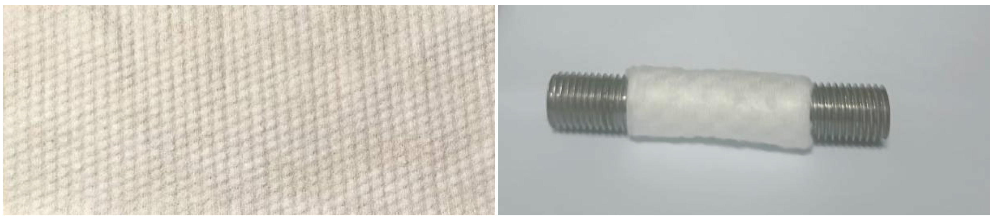
2.1. Metal Round Rod Material

The specimens used in this experiment were smooth metallic cylindrical tensile, a standard geometry for mechanical testing. These specimens were obtained from X80 pipeline steel material (original diameter: 1028 mm). Initial blocks were prepared via hot cutting, followed by sawing to remove heat-affected zones, and final shaping through wire electrical discharge machining and computer numerical control turning machining. The chemical composition is detailed in Table 1, and the specific dimensions of the specimens are illustrated in Figure 3.

2.2. Experimental Environment

The experimental hydrogen pressures were set at 3, 4, and 5 MPa, respectively. The tests were conducted at room temperature (25 °C), The gases employed included N2, H2, and CO (Qingdao Xinkeyuan Technology Co., Ltd., Qingdao, China) with purity exceeding 99.999%, while the liquid-phase reagent was methanol (Tianjin Fuyu Fine Chemicals Co., Ltd., Tianjin, China). Detailed experimental conditions are summarized in Table 2. Three parallel experiments were conducted for each set of conditions, and all calculated results in the following sections are presented as their average values.

2.3. Experimental Facilities

All in situ tensile tests in this study were performed using a pressurized material testing system operating under dynamic loading conditions. The apparatus primarily consists of a 15 MPa hydrogen pressurization system and a high-pressure gas-phase slow strain rate tensile testing machine (Jiangsu Bairuo Test Instruments Co., Ltd., Nanjing, China). A photographic representation of the experimental setup is provided in Figure 4. During the stretching process, sensors will record the specimen elongation and the load in real time, transmit them to the computer terminal, and the stress–strain curves presented in the subsequent sections are generated based on these data.

2.4. Experimental Methods

Specimen Preparation: Pre-test preparation involved the mechanical polishing of machined specimens using 400, 800, 1200, and 2000 grit sandpapers to eliminate machining marks in the gauge section and ensure uniform surface roughness. After polishing and dimensional measurement, the specimens were cleaned in anhydrous ethanol, air-dried at ambient temperature, and stored in a vacuum desiccator until testing.
Operating Instructions for Equipment: The equipment was pre-cleaned by wiping the interface between the bottom of the reactor and the rubber seal with ethanol-saturated cotton to remove contaminants. The specimens were mounted onto tensile rods via threaded ends, and the high-pressure reactor was sealed. Internal vacuum (vacuum < 100 Pa) was followed by three nitrogen purges (0.5 MPa pressure per time) to reduce oxygen content below 0.5 vol%. Hydrogen gas (0.5 MPa pressure per time) was then introduced to displace residual nitrogen. After leaving to set for 12 h at hydrogen environment, tensile testing commenced at a strain rate of 0.03 mm/s. Fractured specimens were taken out from the reactor for hydrogen discharge after being pulled off for dimensional analysis and hydrogen embrittlement index (HEI) calculation.
Methanol Liquid Film Treatment: Under pipeline transport conditions, gas–liquid phase interactions (e.g., dispersed/annular flow) facilitate surface liquid film formation. For high-pressure tensile testing lacking flow control, a porous cotton fiber layer (non-miscible with methanol) was wrapped around the specimens to sustain methanol film coverage (Figure 5). In view of the fact that the thickness of the liquid film on the surface of the specimen cannot be controlled, the experimental part of this paper only studies the influence of the presence of methanol liquid film, and it is considered that the liquid film has an effect when the surface of the specimen is still in a wet state after the experiment.
Evaluation parameters: The strength parameters mainly include the yield strength and ultimate tensile strength, reflecting the ability of material to resist brittle deformation and fracture. The ductility parameters mainly include the reduction in area and elongation after fracture, reflecting the plastic deformation capacity of the material. The hydrogen embrittlement index (HEI) is used to evaluate the hydrogen embrittlement sensitivity of the material. It is calculated via elongation after fracture (Equations (1) and (2)), and higher HEI values usually indicate greater hydrogen susceptibility.
δ = l 1 l l × 100 %
F = δ 0 δ H δ 0 × 100 %
where l 1 , l are the initial and final gauge lengths of the specimen [mm]; δ is the percentage elongation after fracture [%]; δ 0 , δ H are the elongation after fracture in air and hydrogen-containing environments [%]; and F is the hydrogen embrittlement index.

3. Experiment Results and Analyses

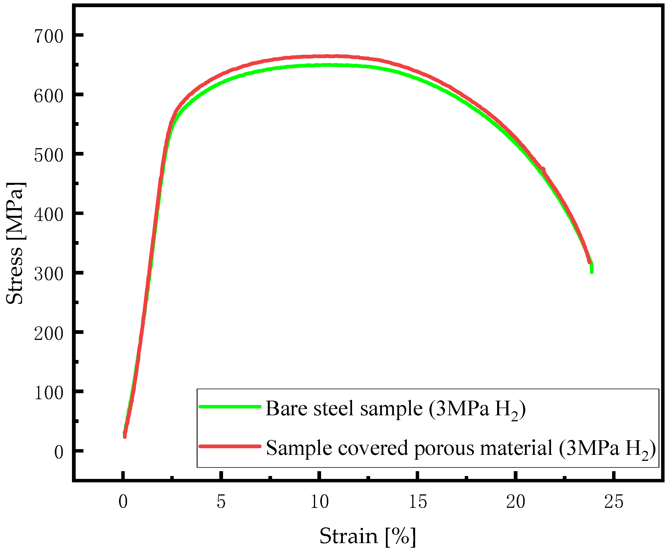
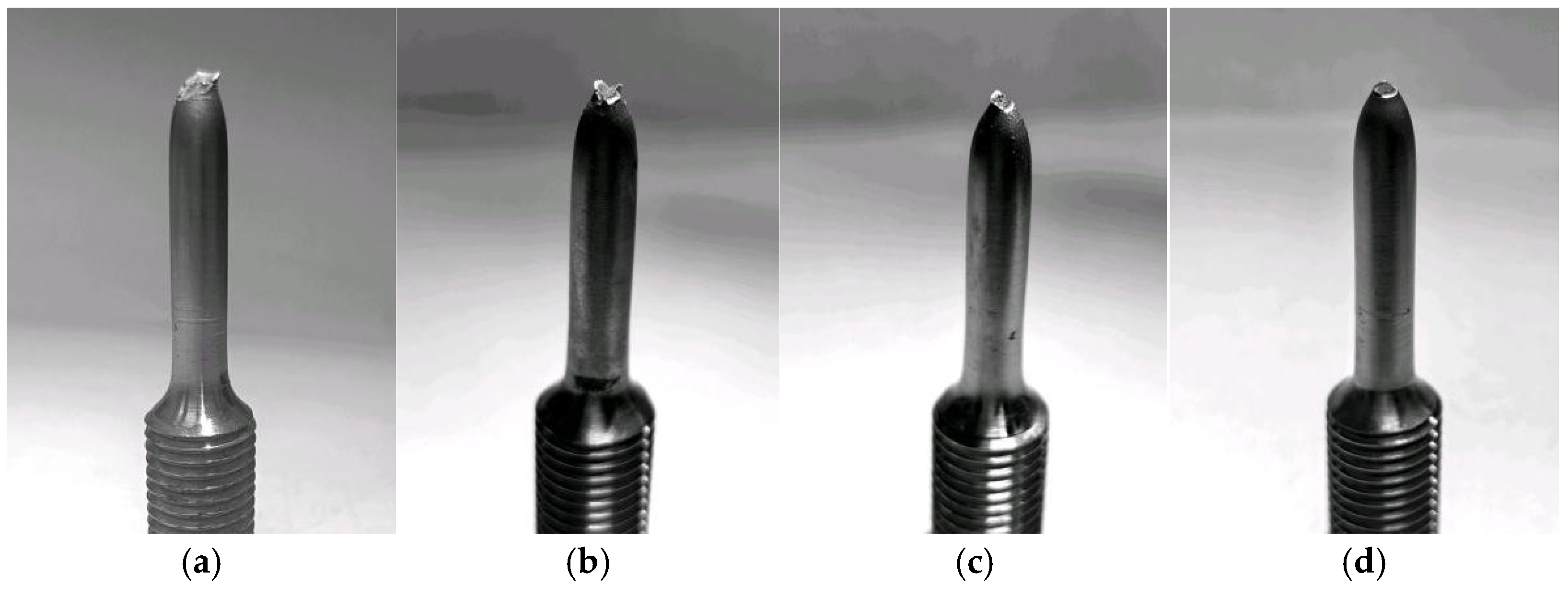
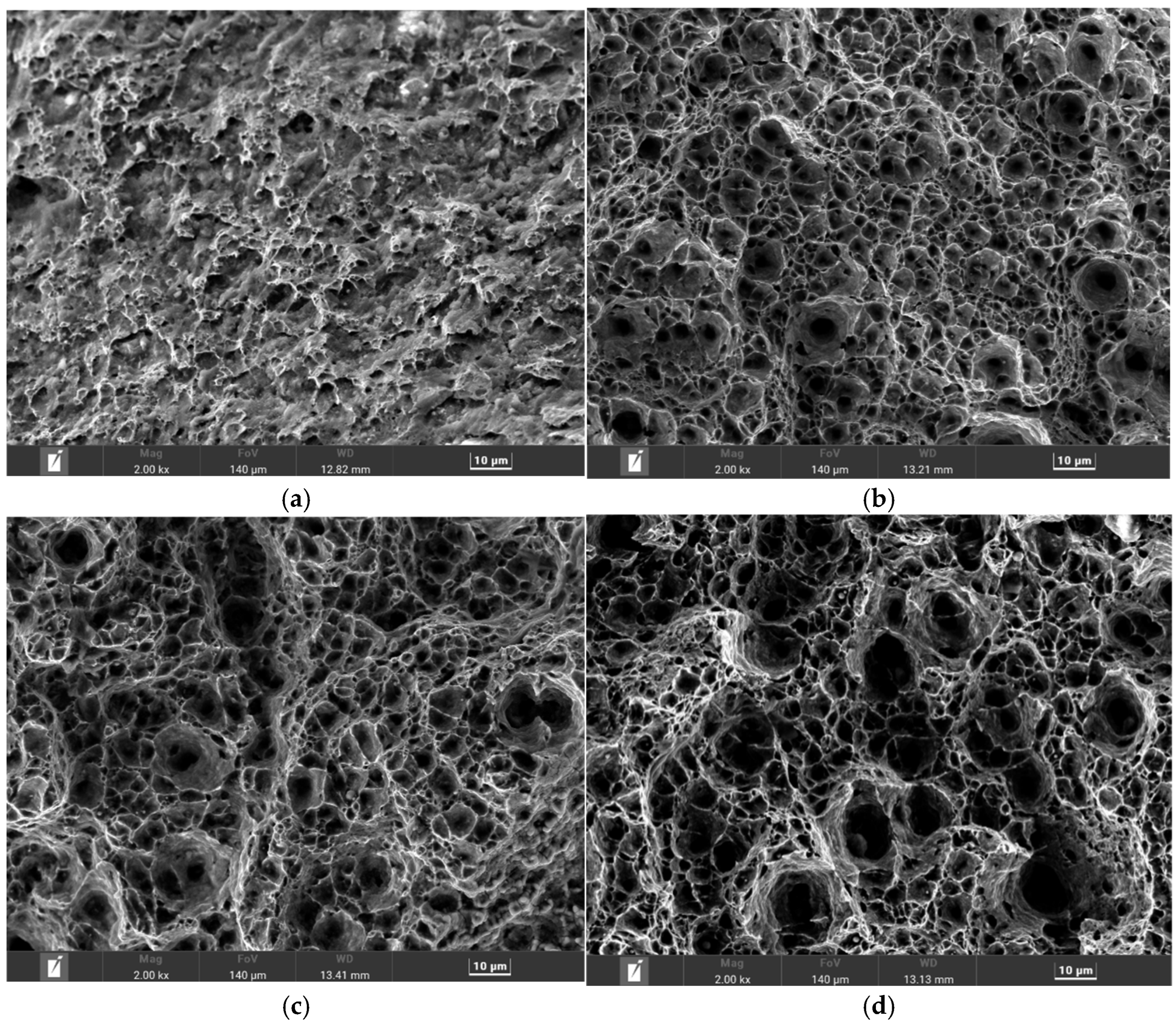
3.1. Effect of Porous Material on Hydrogen Embrittlement Behavior of X80 Steel

Tensile tests were conducted on both bare X80 steel specimen and porous material covered X80 specimens under a 3 MPa H2 environment. A comparative analysis of their calculated stress–strain curves (Figure 6) reveals basically the same curve trends of the two, demonstrating that the presence of porous material imposes no statistically significant impact on the mechanical behavior of X80 pipeline steel under hydrogen environment.

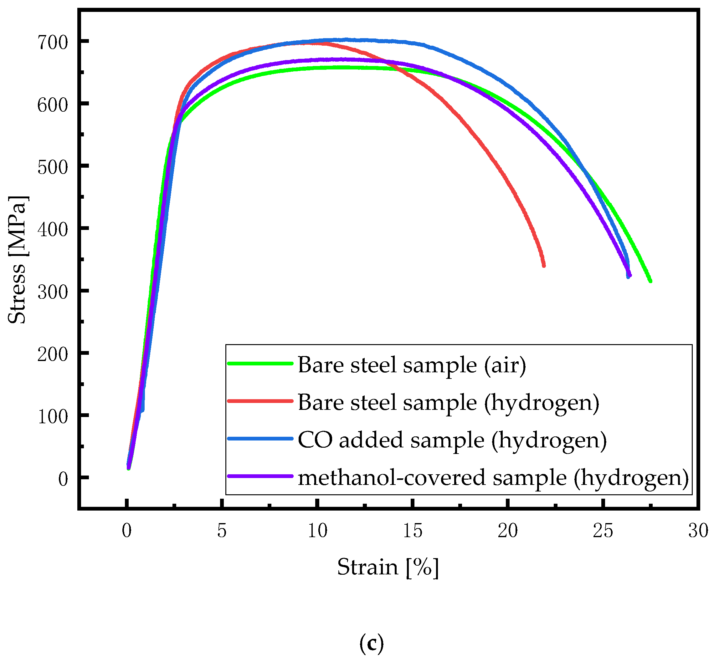
3.2. Effect of Methanol on Mechanical Properties of Pipeline Steel in Hydrogen Environment

To systematically evaluate the inhibition effect of methanol on the hydrogen embrittlement of pipeline steel, CO was used as a comparison object in this paper. While existing research predominantly focuses on gaseous-phase inhibitions, CO demonstrates optimal gaseous suppression performance with maximal efficiency achieved at just 1 vol% concentration [9,10], and there is almost no change after the content exceeds this level. Accordingly, the experiment selects 0.5 MPa CO partial pressure with hydrogen environments of 3–5 MPa H2 for slow strain rate testing.
Figure 7 contrasts fracture morphology under 5 MPa H2 pressure across four treatment conditions, in which the bare steel specimen has more obvious brittle fracture characteristics. The necking phenomenon of the specimens covered by methanol liquid film and the specimens with CO is more obvious, and the cross section morphology of the two specimens is also more similar to that in the air environment. The hydrogen embrittlement degree is relatively smaller too.
Further microstructural analysis of the tensile fracture surfaces was conducted using scanning electron microscopy (Carl Zeiss AG, Oberkochen, Germany), with the results presented in Figure 8. The fracture surface of the bare steel specimen in the hydrogen environment exhibited localized microcracks and minimal dimples, indicating brittle fracture characteristics. In contrast, the methanol liquid film-covered and CO-doped specimens displayed significantly more dimples, suggesting enhanced ductility, whose observations closely resembled the fully ductile fracture features observed in the air environment specimen. These observations are consistent with the macroscopic morphology changes discussed earlier.
The stress–strain curves of the specimens under different hydrogen pressures and treatment conditions were calculated, and the results are shown in Figure 9. As shown in the figure, the stress–strain curves of the specimens under different experimental conditions show nearly identical trends during the elastic deformation stage, with Young’s modulus exhibiting negligible differences. The tensile strengths of bare steel specimens under 3, 4, and 5 MPa hydrogen pressures are statistically analyzed as 649.56, 648.19, and 697.43 MPa, respectively, with the value under 5 MPa pressure being comparatively higher. The coefficient value for tensile strengths of all specimens under 5 MPa is calculated to be 3.74%, which does not exceed 5%, suggesting variations caused by individual differences during specimen processing.
As the hydrogen pressure increases, the elongation of X80 steel gradually decreases, indicating reduced plasticity. The hydrogen embrittlement index for different environments was calculated using Equations (1) and (2), and the results are listed in Table 3. It is evident that the hydrogen embrittlement index increases with the rising hydrogen pressure. Fracture strain values approximately exhibit a negative correlation with hydrogen embrittlement indices. When the hydrogen pressure increases from 3 MPa to 5 MPa, the hydrogen embrittlement index rises from 12.66% to 18.49%, while the fracture strain decreases from 24.67% to 22.45%, indicating reduced plastic deformation capacity and an elevated risk of hydrogen embrittlement.
Further analysis of the effect of methanol liquid film on the mechanical properties of X80 steel reveals that as hydrogen pressure increases, the strain at fracture for methanol-coated specimens gradually decreases, and the hydrogen embrittlement index increases—a trend essentially the same as that of bare steel specimens. However, the hydrogen embrittlement index of bare steel specimens increases significantly faster and remains consistently higher than that of the methanol-covered specimens. Specifically, the elongation of methanol-covered specimens is greater than that of bare steel specimens, with lower plastic loss and less brittle fracture. Specimens with CO addition follow the same trend as methanol-covered specimens. A comparative analysis of the hydrogen embrittlement index results indicates that both treatments exhibit comparable inhibition effects on hydrogen embrittlement, though CO is relatively more stable. While the maximum strain at fracture for both treatments fails to reach levels observed in air environments, both contribute effectively to hydrogen embrittlement mitigation.

4. Analysis of Methanol’s Mechanism

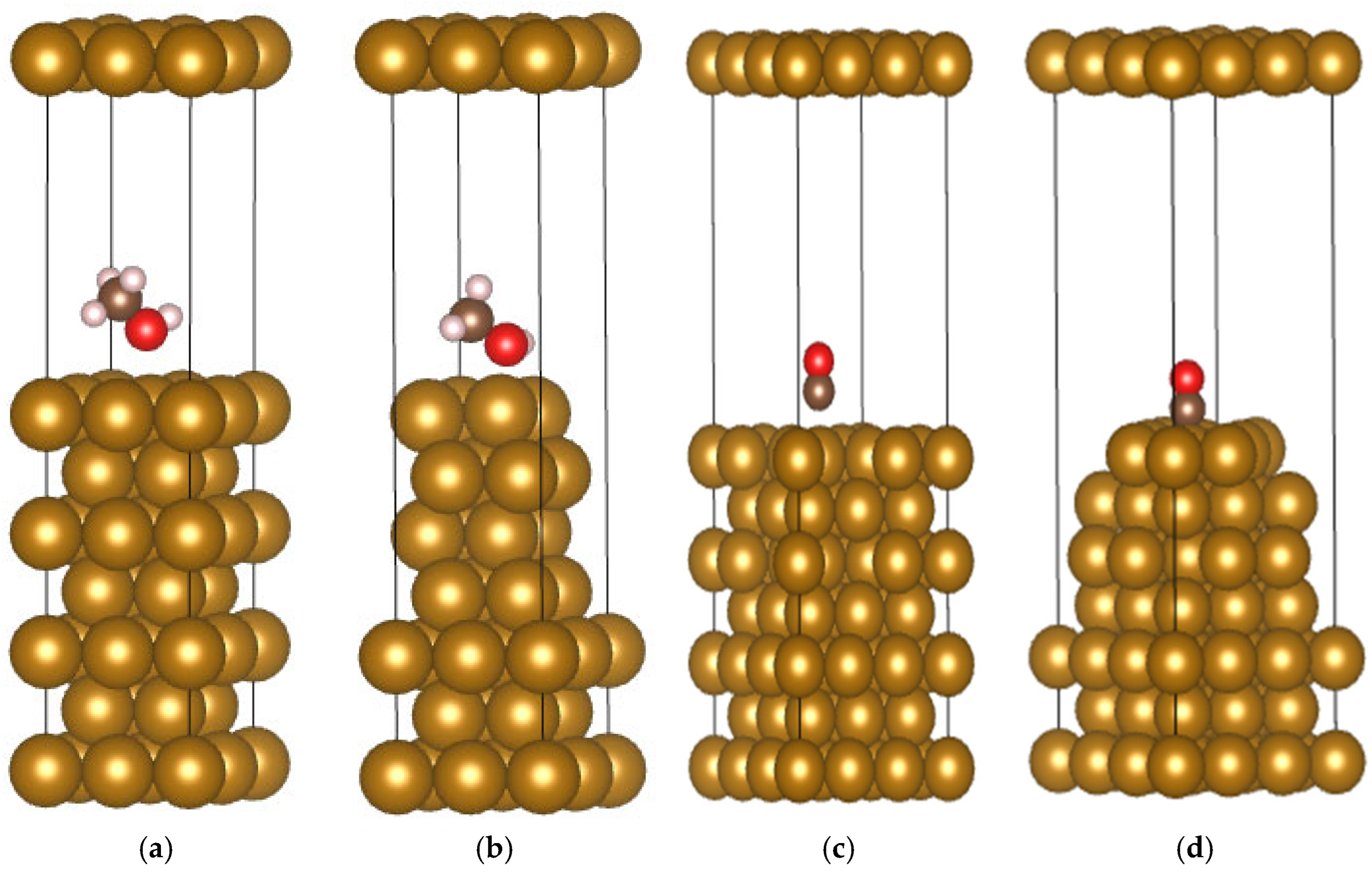
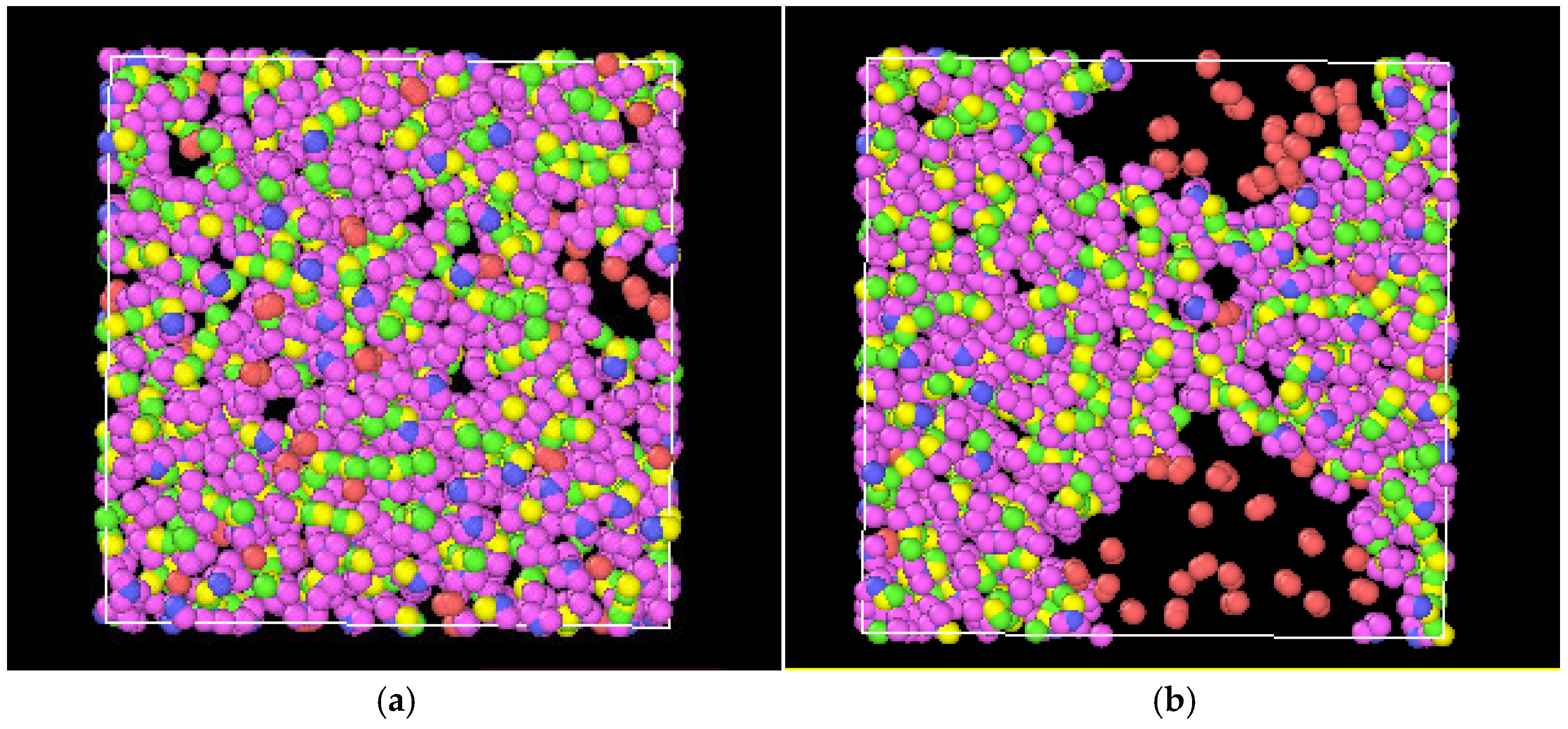
4.1. Adsorption Behavior of Methanol on Pipeline Steel Surfaces

The Fe(110) surface, with the lowest surface energy, is the most stable crystallographic orientation of Fe [27]. Therefore, the Fe unit cell was cleaved along the (110) surface using the Material Studio 2020 (20.1.0.2728) software. A seven-layer atomic slab was constructed, with the bottom four layers fixed and a 15 Å vacuum layer added. Subsequent theoretical calculations were performed using the Vienna Ab initio Simulation Package (VASP.5.4.4), a density functional theory (DFT)-based first-principles computational tool [28]. The plane-wave cutoff energy was set to 425 eV, and the exchange-correlation potential was computed using the revised Perdew Burke Ernzerhof (PBE) functional within the generalized gradient approximation (GGA) [29]. K-point sampling employed the Gamma mode with a 4 × 4 × 4 grid.
Using CO as a comparative reference, adsorption simulations of methanol and CO on the Fe surface were conducted. Geometric optimizations of Fe, methanol, and CO molecules were performed. Based on the optimized Fe surface structure, the adsorption behaviors of methanol and CO were investigated. A top-site (T) adsorption model was established, with the oxygen atom of methanol and the carbon atom of CO positioned directly above the Fe atom. The bottom four metal layers remained fixed, while the top three metal layers and gas molecules were fully relaxed. The configurations before and after VASP optimization are depicted in Figure 10.
The adsorption energies (Eads) of methanol and CO on Fe(110) were calculated based on density functional theory [30], and the optimized results are summarized in Table 4. In the table, h1 and h2 represent the distances between the oxygen atom (methanol) or carbon atom (CO) and the nearest Fe atom before and after optimization, respectively. The simulated CO adsorption energies are in good agreement with previous results (−1.88 [31], −1.95 [32], −2.00 [33]), validating the reasonableness of the selected computational parameters and methodology. An analysis of atomic positions and distance changes indicates that both methanol and CO molecules approach Fe atoms and adsorb on the surface. However, the adsorption energy of CO is significantly higher than that of methanol, implying stronger and more stable adsorption of CO on the Fe surface.

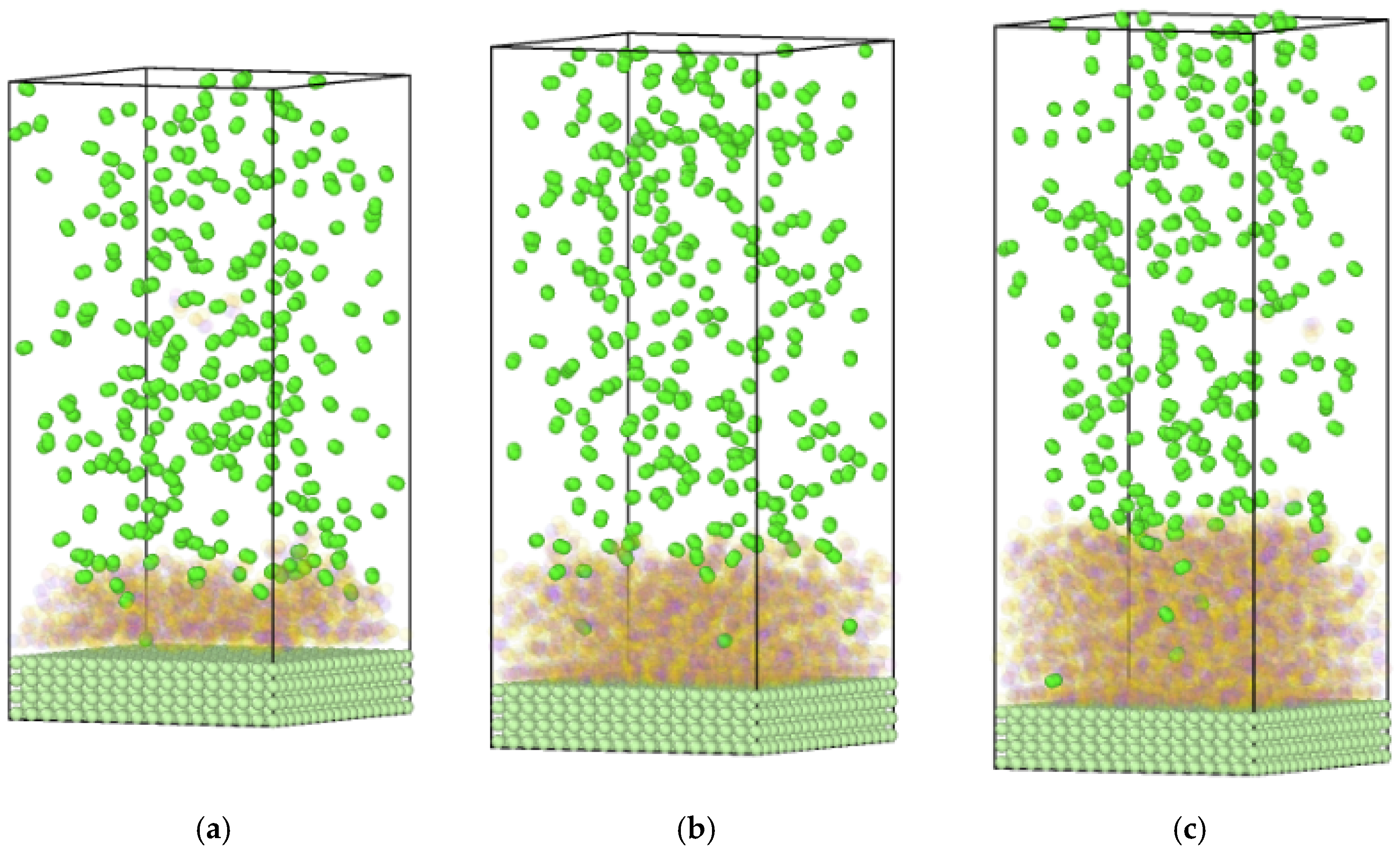
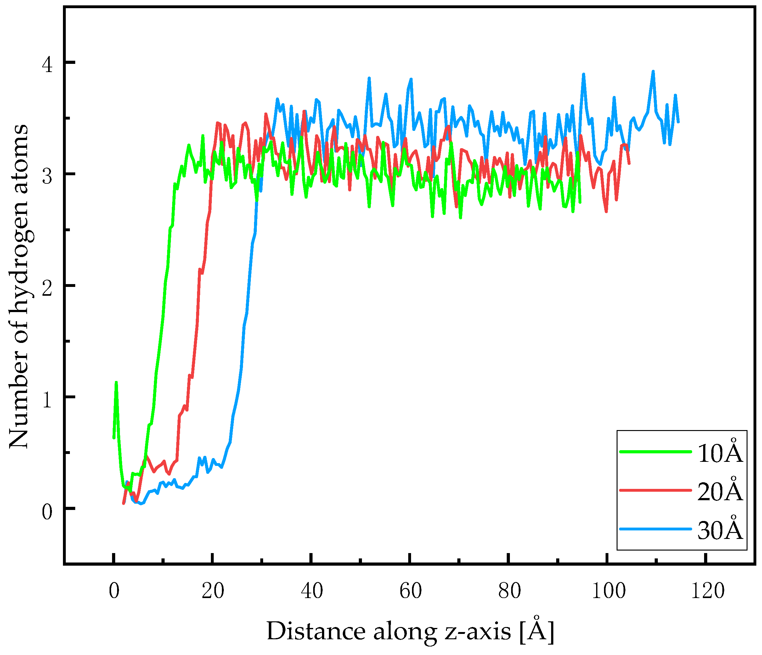
4.2. Diffusion Behavior of Hydrogen in Methanol Liquid Films

Although the adsorption energy of methanol on the Fe surface is significantly lower than that of CO, the experimental results above indicate that the two exhibit almost the same hydrogen embrittlement inhibition effects. Further analysis is required to investigate the physical blocking effect of the methanol film on hydrogen at the Fe surface.
Molecular dynamics simulations were performed using LAMMPS (3 Mar 2020) software to study hydrogen diffusion in methanol (all simulations were conducted at 5 MPa pressure). The OPLS force field [34] was applied to model hydrogen and methanol molecules. The simulation used periodic boundary conditions under the NPT ensemble, with the temperature controlled at 298 K and pressure at 5 MPa. The timestep was set to 1 fs, and the total simulation duration was 2 ns, with data collected every 1 ps. A simulation box (50 × 50 × 10 Å) was constructed, containing approximately 372 methanol molecules (calculated based on density) and 50 randomly placed hydrogen molecules. The initial model is shown in Figure 11. The simulation results reveal significant hydrogen aggregation and phase separation in methanol, demonstrating that hydrogen cannot be readily dissolved in methanol in large quantities.
To further analyze the impact of methanol film on hydrogen distribution, methanol molecular layers with thicknesses of 10, 20, and 30 Å were studied. A hydrogen gas space corresponding to an 85 Å height was constructed, where the calculation of hydrogen number is based on the real gas equation of state and the generalized compressibility chart of the gas space positioned above the methanol molecular layer. The bottommost section was constructed as a seven-layer iron supercell. Fixed boundary conditions were applied along the z-direction, and the NVT ensemble was employed. Other simulation parameters remained consistent with the previous setup. After equilibration, methanol molecules were rendered transparent to visualize hydrogen distribution within the layers (Figure 12). The results show only a small number of hydrogen molecules inside the methanol layers (4, 7, and 11 for 10, 20, and 30 Å thicknesses, respectively), with a sharp increase in hydrogen concentration at the boundary regions.
Over the 1800–2000 ps time window, the average positions of hydrogen atoms were statistically analyzed from 200 equilibrium trajectory frames, and the results are shown in Figure 13. The curves reveal significantly lower hydrogen concentrations in regions covered by the methanol layer compared to uncovered regions. Additionally, as the methanol layer thickness increases, hydrogen molecules penetrate less deeply into the bottom of the layer. These phenomena demonstrate that the methanol molecular layer effectively blocks hydrogen penetration, thus reducing hydrogen concentration at the Fe surface. Unlike gas molecules such as methane and CO, which only reduce hydrogen concentration within probably 6 Å of the Fe surface through near-wall adsorption [35], the liquid methanol forms multi-layer molecular films with dense structures, enabling hydrogen suppression across the entire thickness of the film.

5. Conclusions

The effect of methanol on the mechanical properties of X80 steel was investigated through hydrogen-charged tensile tests, with CO as a comparative reference. Molecular dynamics simulations (VASP and LAMMPS) were employed to study methanol adsorption on the Fe(110) surface and its blocking effect on hydrogen diffusion. The mechanisms underlying methanol’s influence on X80 steel’s mechanical properties are summarized as follows:
Methanol liquid film can inhibit hydrogen embrittlement in X80 steel. As is consistent with bare steel specimens, the hydrogen environment has little effect on methanol liquid film-covered specimens during the elastic deformation stage, and the tensile strength remains largely unchanged. However, under the coverage of methanol, the FS of X80 steel increases, and the HEI decreases, and its hydrogen embrittlement inhibition efficacy matches the optimal performance of CO.
Adsorption energies of methanol and CO on the Fe surface were calculated. Methanol undergoes physical adsorption on Fe with an adsorption energy of probably 0.5, lower than that of CO. Molecular dynamics simulations of hydrogen diffusion in methanol films revealed that methanol effectively obstructs hydrogen diffusion and significantly outperforms gases like methane and CO in reducing near-wall hydrogen concentration. Hence, the liquid methanol film formed on Fe is the primary factor enabling its hydrogen-blocking capability to rival CO.
In summary, compared to gaseous hydrogen embrittlement inhibitors, methanol exhibits a distinct mechanism for suppressing hydrogen embrittlement in pipeline steel under hydrogen environments, yet achieves comparable effectiveness. As methanol and hydrogen are both among the three most widely used fuel cell feedstocks, and methanol serves as a green hydrogen energy carrier, it is suitable for co-transporting methanol through existing hydrogen pipelines. By controlling hydrogen flow velocity and the gas–liquid flow ratio during transportation, annular flow can be established, enabling methanol to form a liquid film covering the pipe wall to simultaneously inhibit hydrogen embrittlement.
However, this study did not regulate methanol liquid film thickness, and the film experienced partial tearing during tensile testing, which diverges from actual operational conditions. Additionally, the research focused solely on X80 steel, while the variety of pipeline steels available is extensive. Therefore, future studies should further investigate the adhesion stability and thickness of the liquid film on experimental specimen surfaces and extend the research to other pipeline steel materials.

Author Contributions

Experiment, L.X.; software, H.Y.; methodology, G.L.; validation, L.C.; investigation, L.X.; data curation, L.C. and J.G.; writing—original draft preparation, J.G., H.Y. and L.X.; writing—review and editing, L.X. and L.C.; supervision, G.L. All authors have read and agreed to the published version of the manuscript.

Funding

This research was funded by the Open Fund Project of CNOOC Key Laboratory of Liquefied Natural Gas and Low-Carbon Technology (KJQZ-2024-1105).

Institutional Review Board Statement

Not applicable.

Informed Consent Statement

Not applicable.

Data Availability Statement

The original contributions presented in this study are included in the article. Further inquiries can be directed to the corresponding author.

Conflicts of Interest

Authors Li Xiao, Jia Gu, Hongwei Yang, Lei Chen and Gang Liu were affiliated to the CNOOC Key Laboratory of Liquefied Natural Gas and Low Carbon Technology. The authors declare that this study received funding from CNOOC Gas & Power Group Co., Ltd. The funder was not involved in the study design, collection, analysis, interpretation of data, the writing of this article or the decision to submit it for publication.

Abbreviations

The following abbreviations are used in this manuscript:
HICHydrogen-induced cracking
HEIHydrogen embrittlement index
FSFracture strain
DFTDensity functional theory
PBEPerdew Burke Ernzerhof
GCAGeneralized gradient approximation

References

  1. U.S. Department of Energy. Hydrogen Strategy Enabling a Low-Carbon Economy; U.S. Department of Energy: Washington, DC, USA, 2020; pp. 51–52.
  2. Zou, C.; Xiong, B.; Xue, H.; Zheng, D.; Ge, Z.; Wang, Y.; Jiang, L.; Pan, S.; Wu, S. The role of new energy in carbon neutral. Pet. Explor. Dev. 2021, 48, 480–491. [Google Scholar] [CrossRef]
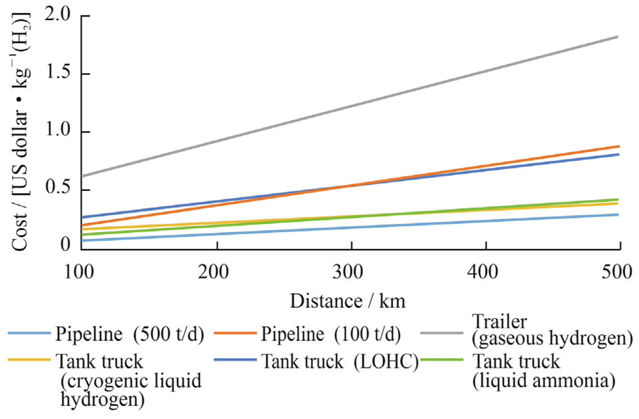
  3. Demir, M.E.; Dincer, I. Cost assessment and evaluation of various hydrogen delivery scenarios. Int. J. Hydrogen Energy 2017, 43, 10420–10430. [Google Scholar] [CrossRef]
  4. Cheng, Y.F. Hydrogen transport in aged pipelines II. Technical assessment of the susceptibility to hydrogen embrittlement. In Proceedings of the AMPP/ASM International Calgary Chapter Luncheon, Calgary, AB, Canada, 15 November 2022; p. 8. [Google Scholar]
  5. Ohaeri, E.; Eduok, U.; Szpunar, J. Hydrogen related degradation in pipeline steel: A review. Int. J. Hydrogen Energy 2018, 43, 14584–14617. [Google Scholar] [CrossRef]
  6. Cazenave, P.; Jimenez, K.; Gao, M.; Moneta, A.; Hryciuk, P. Hydrogen assisted cracking driven by cathodic protection operated at near−1,200 mV CSE—An onshore natural gas pipeline failure. J. Pipeline Sci. Eng. 2021, 1, 100–121. [Google Scholar] [CrossRef]
  7. Li, K.; Zeng, Y.; Luo, J. Influence of H2S on the general corrosion and sulfide stress cracking of pipeline steels for supercritical CO2 transportation. Corros. Sci. 2021, 190, 109639. [Google Scholar] [CrossRef]
  8. Robertson, I.M.; Sofronis, P.; Nagao, A.; Martin, M.L.; Wang, S.; Gross, D.W.; Nygren, K.E. Hydrogen embrittlement understood. Metall. Mater. Trans. B 2015, 46, 1085–1103. [Google Scholar] [CrossRef]
  9. Wang, J.; Xu, N.; Wu, T.; Xi, X.; Wang, G.; Chen, L. Response of hydrogen diffusion and hydrogen embrittlement to Cu addition in low carbon low alloy steel. Mater. Charact. 2023, 195, 112478. [Google Scholar] [CrossRef]
  10. Lv, W.; Yu, W.; Wu, Z.; Yan, Y.; Shi, J.; Wang, M. Hydrogen Embrittlement Susceptibility of a Newly Developed Grain-Refined Ultra-High Strength Steel. Materials 2025, 18, 987. [Google Scholar] [CrossRef]
  11. Chen, Y.S.; Huang, C.; Liu, P.Y.; Yen, H.W.; Niu, R.; Burr, P.; Moore, K.L.; Martínez-Pañeda, E.; Atrens, A.; Cairney, J.M. Hydrogen trapping and embrittlement in metals—A review. Int. J. Hydrogen Energy 2024. [CrossRef]
  12. Wan, H.; Min, W.; Song, D.; Chen, C. Research progress of hydrogen blocking coatings. Mater. Chem. Phys. 2024, 328, 130028. [Google Scholar] [CrossRef]
  13. Röthig, M.; Hoschke, J.; Tapia, C.; Venezuela, J.; Atrens, A. A review of gas phase inhibition of gaseous hydrogen embrittlement in pipeline steels. Int. J. Hydrogen Energy 2024, 60, 1239–1265. [Google Scholar] [CrossRef]
  14. Zou, C.; Li, J.; Zhang, X.; Jin, X.; Xiong, B.; Yu, H.; Liu, X.; Wang, S.; Li, Y.; Zhang, L.; et al. Industrial status, technological progress, challenges, and prospects of hydrogen energy. Nat. Gas Ind. B 2022, 9, 427–447. [Google Scholar] [CrossRef]
  15. International Energy Agency (IEA). The Future of Hydrogen; IEA: Paris, France, 2019. [Google Scholar]
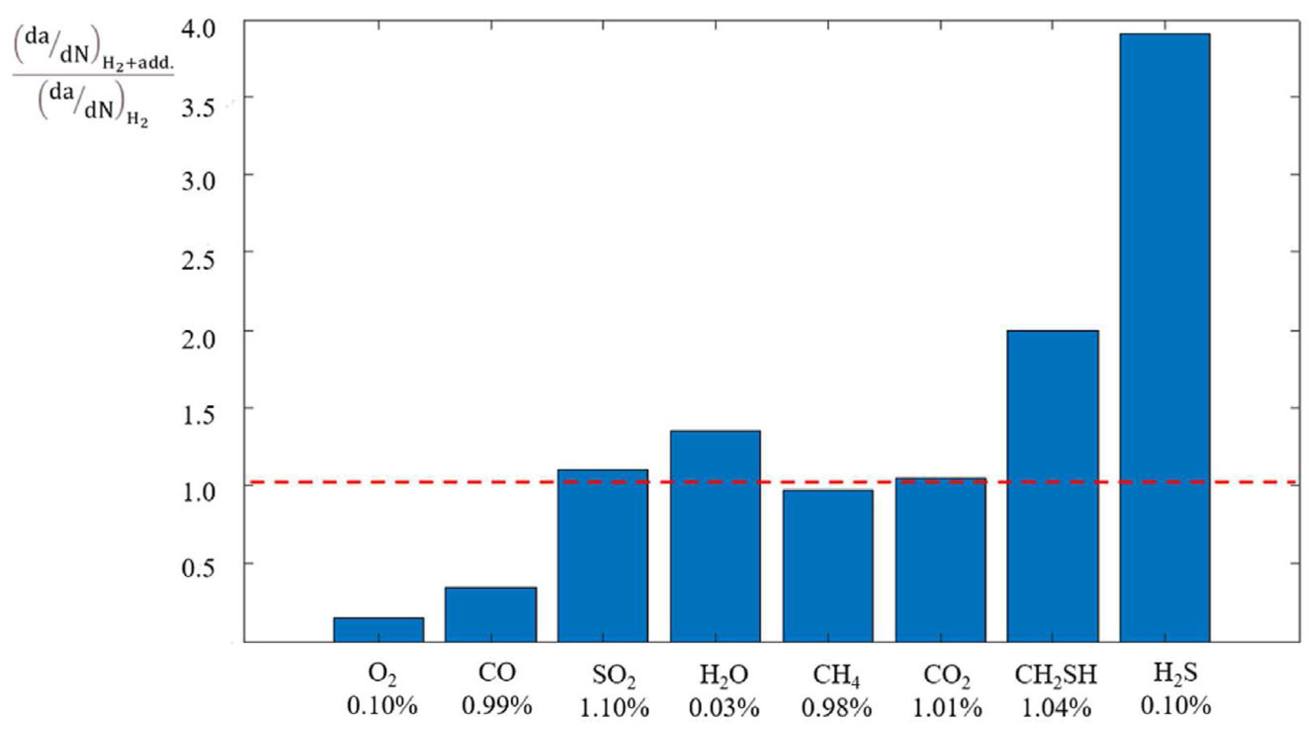
  16. Staykov, A.; Yamabe, J.; Somerday, B.P. Effect of hydrogen gas impurities on the hydrogen dissociation on iron surface. Int. J. Quantum Chem. 2014, 114, 626–635. [Google Scholar] [CrossRef]
  17. Staykov, A.; Komoda, R.; Kubota, M.; Ginet, P.; Barbier, F.; Furtado, J. Coadsorption of CO and H2 on an iron surface and its implication on the hydrogen embrittlement of iron. J. Phys. Chem. C 2019, 123, 30265–30273. [Google Scholar] [CrossRef]
  18. Liu, C.; Yang, H.; Wang, C.; Zhang, H.; Ding, R.; Ai, L.; Fan, X.; Zhang, R.; Xu, X.; Ning, Y.; et al. Effects of CH4 and CO on hydrogen embrittlement susceptibility of X80 pipeline steel in hydrogen blended natural gas. Int. J. Hydrogen Energy 2023, 48, 27766–27777. [Google Scholar] [CrossRef]
  19. Zhang, N.; Komoda, R.; Yamada, K.; Kubota, M.; Staykov, A. Ammonia mitigation and induction effects on hydrogen environment embrittlement of SCM440 low-alloy steel. Int. J. Hydrogen Energy 2022, 47, 15084–15093. [Google Scholar] [CrossRef]
  20. Nagy, H.; Tamany, E.; Ashour, H.; El-Azabawy, O.E.; Zaki, E.G.; Elsaeed, S.M. Polymeric ionic liquids based on benzimidazole derivatives as corrosion inhibitors for X65 carbon steel deterioration in acidic aqueous medium: Hydrogen evolution and adsorption studies. ACS Omega 2020, 5, 30577–30586. [Google Scholar] [CrossRef]
  21. Bentrah, H.; Rahali, Y.; Chala, A. Gum Arabic as an eco-friendly inhibitor for API 5L X42 pipeline steel in HCl medium. Corros. Sci. 2014, 82, 426–431. [Google Scholar] [CrossRef]
  22. Campari, A.; Ustolin, F.; Alvaro, A.; Paltrinieri, N. A review on hydrogen embrittlement and risk-based inspection of hydrogen technologies. Int. J. Hydrogen Energy 2023, 48, 35316–35346. [Google Scholar] [CrossRef]
  23. San Marchi, C.; Somerday, B.P. Effects of high-pressure gaseous hydrogen on structural metals. SAE Trans. 2007, 116, 94–109. [Google Scholar]
  24. Bai, Z.; Liu, Q.; Lei, J.; Li, H.; Jin, H. A polygeneration system for the methanol production and the power generation with the solar–biomass thermal gasification. Energy Convers. Manag. 2015, 102, 190–201. [Google Scholar] [CrossRef]
  25. Xu, Y.; Wang, L.; Zhou, Q.; Li, Y.; Liu, L.; Nie, W.; Xu, R.; Zhang, J.; Cheng, Z.; Wang, H.; et al. Carbon dioxide enabled hydrogen storage by methanol: Highly selective and efficient catalysis with well-defined heterogeneous catalysts. Coord. Chem. Rev. 2024, 508, 215775. [Google Scholar] [CrossRef]
  26. Ishaq, H.; Dincer, I. Evaluation of a wind energy based system for co-generation of hydrogen and methanol production. Int. J. Hydrogen Energy 2020, 45, 15869–15877. [Google Scholar] [CrossRef]
  27. Yu, C. Study on Microstructure and Properties of Low Temperature X80 Pipeline Steel. Ph.D. Thesis, Xi’an Shiyou University, Xi’an, China, 2020. [Google Scholar]
  28. Kresse, G.; Furthmüller, J. Efficiency of ab-initio total energy calculations for metals and semiconductors using a plane-wave basis set. Comput. Mater. Sci. 1996, 6, 15–50. [Google Scholar] [CrossRef]
  29. Perdew, J.P.; Burke, K.; Ernzerhof, M. Generalized gradient approximation made simple. Phys. Rev. Lett. 1996, 77, 3865–3868. [Google Scholar] [CrossRef]
  30. Zeinalipour-Yazdi, C.D.; Cooksy, A.L.; Efstathiou, A.M. CO adsorption on transition metal clusters: Trends from density functional theory. Surf. Sci. 2008, 602, 1858–1862. [Google Scholar] [CrossRef]
  31. Wang, T.; Tian, X.X.; Li, Y.W.; Wang, J.; Beller, M.; Jiao, H. Coverage-dependent CO adsorption and dissociation mechanisms on iron surfaces from DFT computations. ACS Catal. 2014, 4, 1991–2005. [Google Scholar] [CrossRef]
  32. Stibor, A.; Kresse, G.; Eichler, A.; Hafner, J. Density functional study of the adsorption of CO on Fe(110). Surf. Sci. 2002, 507, 99–102. [Google Scholar] [CrossRef]
  33. Sun, X.; Förster, S.; Li, Q.X.; Kurahashi, M.; Suzuki, T.; Zhang, J.W.; Yamauchi, Y.; Baum, G.; Steidl, H. Spin-polarization study of CO molecules adsorbed on Fe (110) using metastable-atom deexcitation spectroscopy and first-principles calculations. Phys. Rev. B 2007, 75, 035419. [Google Scholar] [CrossRef]
  34. Jorgensen, W.L.; Maxwell, D.S.; Tirado-Rives, J. Development and testing of the OPLS all-atom force field on conformational energetics and properties of organic liquids. J. Am. Chem. Soc. 1996, 118, 11225–11236. [Google Scholar] [CrossRef]
  35. Liu, G.; Cui, Z.; Wei, J.; Chen, L.; Jiang, B.; Li, D.; Xie, C. Inhibition of hydrogen embrittlement induced by CH4 in pipeline transportation of hydrogen-natural gas mixtures. Oil Gas Storage Transp. 2023, 42, 16–23. [Google Scholar]
Figure 2. Ratio of fatigue crack growth rates of different gases. Reprinted from Ref. [22] and Reprinted with permission from Ref. [23]. Copyright 2025 Copyright SAE International.
Metals 15 00429 g002
Figure 3. Round rods of metal for experiments. (a) Size of specimens, (b) specimen material.
Metals 15 00429 g003
Figure 4. Material testing machine under pressure and dynamic loading conditions. (a) High-pressure gas-phase slow strain rate tensile testing machine, (b) 15 MPa hydrogen pressurization system.
Metals 15 00429 g004
Figure 5. Porous material (left) and metal rod specimen covered with it (right).
Metals 15 00429 g005
Figure 6. Stress–strain curves of coated porous material covered specimen and bare steel specimen under 3 MPa hydrogen environment.
Metals 15 00429 g006
Figure 7. Fracture morphology of each specimen under 5 MPa hydrogen pressure and in air environment. (a) Bare steel specimen in hydrogen environment, (b) specimen covered with methanol liquid film in hydrogen environment, (c) specimen with CO addition in hydrogen environment, (d) bare steel specimen in air environment.
Metals 15 00429 g007
Figure 8. Microscopic fracture morphology of each specimen under 5 MPa hydrogen pressure and in air environment. (a) Bare steel specimen in hydrogen environment, (b) specimen covered with methanol liquid film in hydrogen environment, (c) specimen with CO addition in hydrogen environment, (d) bare steel specimen in air environment.
Metals 15 00429 g008
Figure 9. Stress–strain curves of specimens under different hydrogen pressures: (a) 3 MPa, (b) 4 MPa, (c) 5 MPa.
Metals 15 00429 g009aMetals 15 00429 g009b
Figure 10. Configurations of methanol and CO before and after adsorption optimization. (a) Initial configuration of methanol, (b) optimized configuration of methanol, (c) initial configuration of CO, (d) optimized configuration of CO.
Metals 15 00429 g010
Figure 11. States of hydrogen in methanol before and after equilibration. (Red particles: hydrogen molecules; other colored particles: CHO groups in methanol). (a) Initial model, (b) equilibrium configuration.
Metals 15 00429 g011
Figure 12. Equilibrium models under varying methanol layer thicknesses (dark green particles: hydrogen molecules): (a) 10 Å, (b) 20 Å, (c) 30 Å.
Metals 15 00429 g012
Figure 13. Hydrogen atom distribution along Z-direction for different methanol layer thicknesses.
Metals 15 00429 g013
Table 1. Chemical composition of X80 pipeline steel [t, %].
ElementContentElementContentElementContentElementContent
Fe96.741Nb0.11Cr0.24Sb0.011
Mn1.70Ti0.016Mo0.24Co0.008
C0.09Ni0.26Si0.31Se0.002
P0.004V0.005Cu0.19As0.006
Bi0.005Pb0.005Al0.036Ta0.021
Table 2. Experimental environment.
Serial NumberExperimental Environment
1air
23 MPa H2
33 MPa H2 + CH3OH
44 MPa H2
54 MPa H2 + CH3OH
65 MPa H2
75 MPa H2 + CH3OH
Table 3. Hydrogen embrittlement index and fracture strain (FS) value for different environments.
Hydrogen Pressure [MPa]Bare SpecimenMethanol Covered SpecimenCO Added
Specimen
HEIFSHEIFSHEIFS
312.66 ± 1.8524.67 ± 0.734.75 ± 1.1126.10 ± 0.644.27 ± 1.2126.38 ± 0.38
416.93 ± 2.3922.72 ± 0.946.23 ± 2.9825.58 ± 1.875.96 ± 1.1925.83 ± 0.59
518.49 ± 0.7422.45 ± 0.646.67 ± 2.8525.50 ± 1.196.76 ± 1.4925.71 ± 0.61
Table 4. Adsorption-related data of methanol and CO on Fe(110) surface.
Adsorbateh1 [Å]h2 [Å]Eads [eV]
methanol2.7612.238−0.505
CO2.5761.768−1.912
Disclaimer/Publisher’s Note: The statements, opinions and data contained in all publications are solely those of the individual author(s) and contributor(s) and not of MDPI and/or the editor(s). MDPI and/or the editor(s) disclaim responsibility for any injury to people or property resulting from any ideas, methods, instructions or products referred to in the content.

