Article

Research on the Influence of Mo on the Corrosion Mechanism of 1%Ni Weathering Steel in Simulated Marine Atmospheric Environments

by
Chengliang Han
1,
Qiang Yu
2,
Shibiao Wang
1,
Mingliang Qiao
1,3 and
Qingfeng Wang
1,*
1
State Key Laboratory of Metastable Materials Science & Technology, Yanshan University, Qinhuangdao 066004, China
2
Department of Chemistry and Chemical Engineering, Cangzhou Normal University, Cangzhou 061001, China
3
Nanjing Iron & Steel Co., Ltd., Nanjing 210035, China
*
Author to whom correspondence should be addressed.
Metals 2025, 15(4), 430; https://doi.org/10.3390/met15040430
Submission received: 23 December 2024 / Revised: 3 April 2025 / Accepted: 4 April 2025 / Published: 11 April 2025

Abstract

This study focuses on researching the influence of Mo on the corrosion mechanism of 1%Ni weathering steel (WS) in simulated marine atmospheric conditions. The Mo element is involved in the reaction, and after hydrolysis, MoO2 and MoO3 are produced. The deposition of MoO2 and MoO3 occurs in cracks and fissures, rendering the rust layer more uniform and homogeneous. It also furnishes nucleation sites for amorphous oxyhydroxide, which in turn promotes the interweaving of a nanosized oxyhydroxide network. As a result, the rust layer develops into a physical barrier that acquires a protective capacity. Only some of the Mo ions migrate to the vicinity of the Ni element for the hydrolysis reaction, which leads to the difficulty in improving the corrosion rate of the steel with a high Mo content. Hence, the content of Mo element can be controlled within 0.3–0.5% for the 1Ni WS.

1. Introduction

With the development of the Belt and Road Initiative, the demand for maritime transportation continues to increase [1,2]. The use of traditional WS is widespread in the transportation field due to its high corrosion resistance property without painting in typical atmospheric environments. However, the rust layer of WS is always broken in marine atmospheric environments, and this limits its application [3,4]. To address the challenges posed by diverse coastal climatic conditions, an advanced 3%Ni WS formulation was engineered to provide superior resistance against marine environmental stressors. This innovative material solution has demonstrated operational effectiveness in real-world deployments across Spanish coastal infrastructures and Japanese marine facilities, where it has proven its durability under varied atmospheric exposures [5].
The Ni-advanced WS demonstrates exceptional resistance to marine atmospheric corrosion via the synergistic development of dual protective mechanisms at the rust layer [3,6]. Refs. [7,8] elucidated the dual-functional role of Ni in corrosion mitigation: (1) The Ni element can form NiFe2O4 within the rust layer. This structural transformation accelerates the nucleation of thermodynamically stable α-FeOOH nanophases, resulting in the formation of a dense, homogenized oxide barrier that effectively impedes electrolyte infiltration. (2) The Ni additive induces cationic selectivity within the rust matrix, promoting the formation of a semi-permeable passive layer that selectively blocks chloride ion penetration while permitting benign ionic transport. Noteworthy is the observation that excessive nickel incorporation (>3.5 wt%) does not proportionally enhance corrosion resistance, underscoring the necessity for precise compositional optimization to balance barrier efficacy with material stability [9]. Furthermore, considering the high expense of element Ni and its commercial availability, scholars are concentrating on suitably reducing the amount of Ni elements and adding other elements in combination to enhance the WS corrosion resistance [10].
Moreover, recent studies have demonstrated that incorporating approximately 1%Ni into WS significantly enhances its corrosion resistance in coastal atmospheric environments. Xu et al. established that the corrosion resistance of WS could be effectively strengthened by incorporating Al and Mo elements into the 1%Ni WS [11]. Thus, it represents a practical strategy to introduce additional corrosion-resistant elements to boost the corrosion resistance based on the 1%Ni WS. T. Nishimura [12] and Hao [13] reported that the Mo component undergoes oxidative transformation into Mo-containing ionic species during corrosion progression, functioning as an effective corrosion inhibitor. Hashimoto’s research highlighted the challenge in establishing stable surface passivation at electrochemically active WS sites under marine conditions [14]. Meanwhile, the additive Mo demonstrates unique surface-modifying capabilities by forming protective molybdenum hydroxide/molybdate complexes at these active locations. This transformation not only neutralizes localized corrosion nuclei but also promotes the development of a contiguous passive layer with enhanced uniformity [15]. Furthermore, Mo-doped WS systems exhibit elevated corrosion potentials in chloride-rich environments, indicating improved thermodynamic stability of the rust layer. The strategic incorporation of low-concentration molybdenum into 1%Ni-WS formulations presents dual advantages: (1) cost-effective material design through reduced noble metal usage, and (2) synergistic enhancement of barrier properties through the combined action of nickel-induced phase stabilization and a molybdenum-mediated surface rust layer. This innovative material strategy warrants systematic investigation into the interactive mechanisms between Mo and Ni within the oxide matrix. Such studies could unlock the development of next-generation WS optimized for marine applications, balancing exceptional anti-corrosion performance with economic viability through rational element synergism.
In this research, we carried out a corrosion test to simulate marine atmospheric conditions in order to examine the role of varying amounts of Mo alloying elements in 1 wt% Ni WS. The cross-section of the rust layer and the distribution of elements were observed using a scanning electron microscope (SEM). The phase composition of the rust layer was analyzed by X-ray diffraction (XRD). The electrochemical behavior of steel corrosion at different time intervals was characterized through EIS and Tafel. Eventually, the impact of Mo on the corrosion mechanism of 1%Ni WS in the simulated marine atmospheric environment was elucidated.

2. Experiments

2.1. Samples

This study investigation utilized a novel 1%Ni WS alloy produced via a 100 kg vacuum induction furnace. Three distinct steel variants with systematic molybdenum additions were subjected to compositional analysis using X-ray fluorescence spectrometry (XRF) (Hitachi, X-MET8000, Tokyo, Japan), with their respective chemical profiles detailed in Table 1. For benchmarking purposes, conventional Q235 steel was incorporated as the reference material throughout the comparative testing protocol.
Figure 1 shows the microstructure of WS. The microstructure of the three WS showed no obvious difference. They were mainly composed of bainite and ferrite, and the ferrite and bainite were interleaved, and there were island structures along the edges of some ferrite and bainite.

2.2. Corrosion Test

In accordance with TB/T 2375-1993 (Test Method for Cyclic Infiltration Corrosion Evaluation of Railway Weathering Steels), rectangular coupons measuring 60 mm × 40 mm × 4 mm were prepared per standard specifications [16]. The accelerated corrosion protocol required quadruplicate sample sets per experimental condition, with triplicate specimens allocated for corrosion kinetic studies and a dedicated sample retained for corrosion product layer characterization. Surface pretreatment involved sequential abrasion using #150-1500 grit silicon carbide paper to achieve mirror-finish surfaces, followed by ultrasonic degreasing in acetone. Post-cleaning procedures included forced-air drying, and equilibration in desiccators for 24 h preceding electrochemical testing. The parameters of wet-dry cyclic corrosion test are shown in Table 2.
The corrosion kinetics were quantified through mass loss quantification. Following initial characterization using a microbalance (0.1 mg resolution) to establish baseline mass (W0), specimens underwent immersion in 1 L of 0.5 M HCl solution containing 3.5 g hexamine inhibitor. The electrochemical cleaning protocol involved 600 s ultrasonic treatment with dynamic fluid circulation at 25 ± 0.5 °C, effectively removing surface oxides to obtain stabilized mass values (Wt). This standardized procedure ensured measurement reproducibility across experimental cycles. Corrosion rate calculations (R, mg·cm−2·h−1) were performed according to the following derivation:
R = w 0 w t S t
where ΔW (mg·cm−2·h−1) represents the specific mass loss of the specimen, with W0 and Wt denoting the initial and post-corrosion weights, respectively, S (cm2) corresponding to the effective surface area exposed to the electrolyte, and t (h) indicating the total immersion duration.

2.3. Analysis of the Corrosion Products

In this investigation, surface morphologies of four specimens exposed to simulated NaCl-contaminated atmospheric environments were documented using high-resolution digital imaging. A phase composition analysis of the rust layers was performed using a Rigaku D/max-2500/PC (Rigaku, Tokyo, Japan) with Cu-Kα radiation. Angular scanning was conducted from 10° to 70° (2θ) at 0.02° intervals under operational parameters of 40 kV accelerating voltage and 200 mA tube current. Microstructural characterization of both surface features and cross-sectional profiles at various corrosion stages was achieved through Hitachi S-3400N scanning electron microscopy (Hitachi, Tokyo, Japan). The SEM observations were carried out under optimized imaging conditions of 15 kV acceleration voltage and 40 mA probe current.

2.4. Electrochemical Measurements

Electrochemical characterization was performed using a standard three-electrode configuration under ambient conditions (25 ± 1 °C). Cubic specimens (10 × 10 × 4 mm3) machined from the experimental alloy underwent surface preparation involving abrasive finishing of five non-corroded faces with progressively refined SiC papers. Electrical connectivity was established through backside soldering prior to epoxy resin encapsulation in PVC tubing, forming the working electrode assembly. The electrochemical cell comprised a platinum mesh counter electrode and saturated calomel reference (SCE) immersed in 3.5 wt% NaCl electrolyte. Preconditioning involved 60 min electrolyte immersion to stabilize interfacial conditions before initiating open-circuit potential (OCP) monitoring over 600 s. Upon achieving OCP stability (<2 mV/min drift), electrochemical impedance spectroscopy (EIS) measurements were conducted across 10−2–105 Hz frequency range with ±10 mV AC perturbation. Subsequent potentiodynamic polarization employed a −1.0 V to −0.1 V potential window at 1.67 mV/s scan rate, referenced against the stabilized OCP value.

3. Results

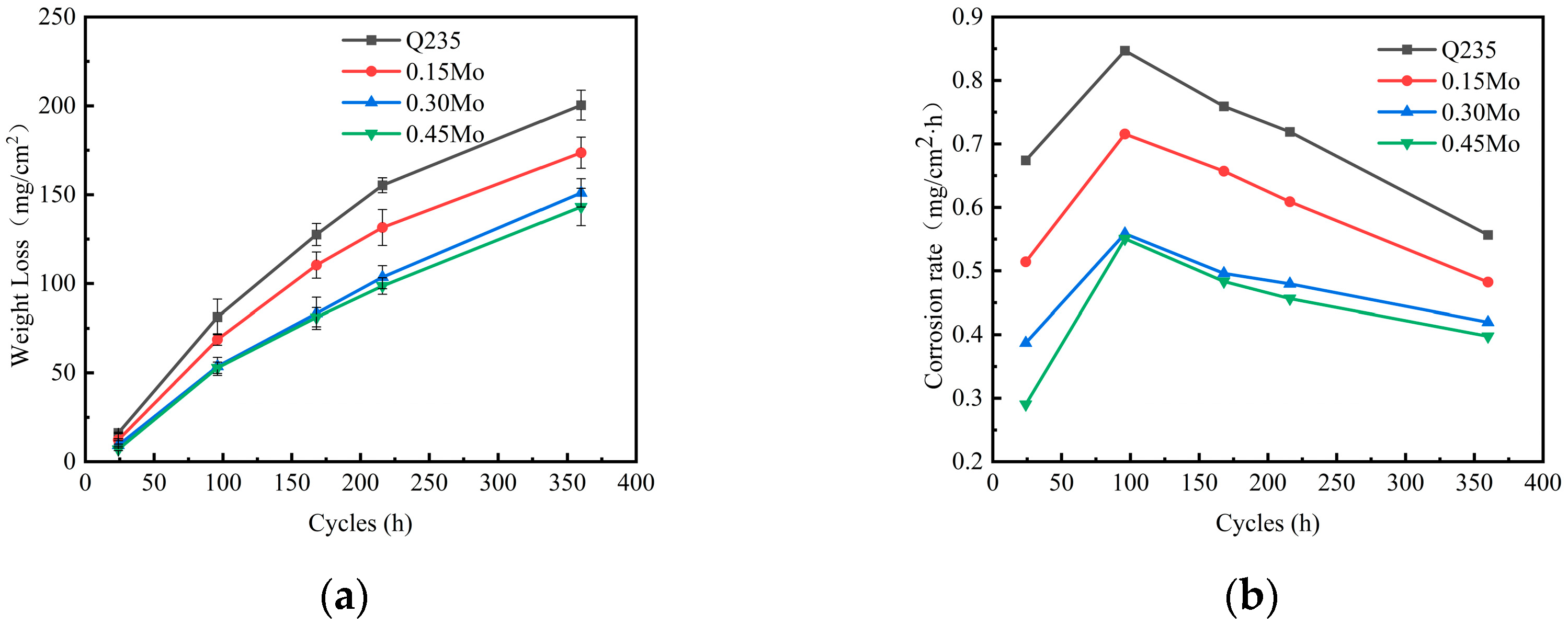
3.1. Corrosion Kinetics

Figure 2a presents the weight losses of four samples are increased with the corrosion process prolonging. Among the four specimens tested, Q235 demonstrated the most significant mass reduction under specified experimental conditions, and the weight loss was about 200 mg/cm2 for the five cycles (360 h). The weight loss of 0.45Mo was the smallest of the four samples, and the weight loss was about 143 mg/cm2 in the later corrosion process. Meanwhile, the weight losses of four samples gradually decreased with the increase in the Mo content in each cycle. Although the weight loss of 0.45Mo is the least, the corrosion weight loss of 0.30Mo is basically similar to that of 0.45Mo. Figure 1b shows that the corrosion rate for four samples rose at first in the initial corrosion process (<96 h) and then decreased in the later corrosion process (>96 h). The corrosion rates of the four samples gradually decreased with the increase in the Mo content in each cycle, and that of 0.45Mo is the lowest at about 0.40 (mg/cm2·h). However, when the Mo content exceeded 0.30 wt%, the corrosion rate exhibited no marked reduction. This observation indicates that the Mo content within a certain range enhances the corrosion resistance of 1%Ni WS in the simulated marine atmospheric environment.

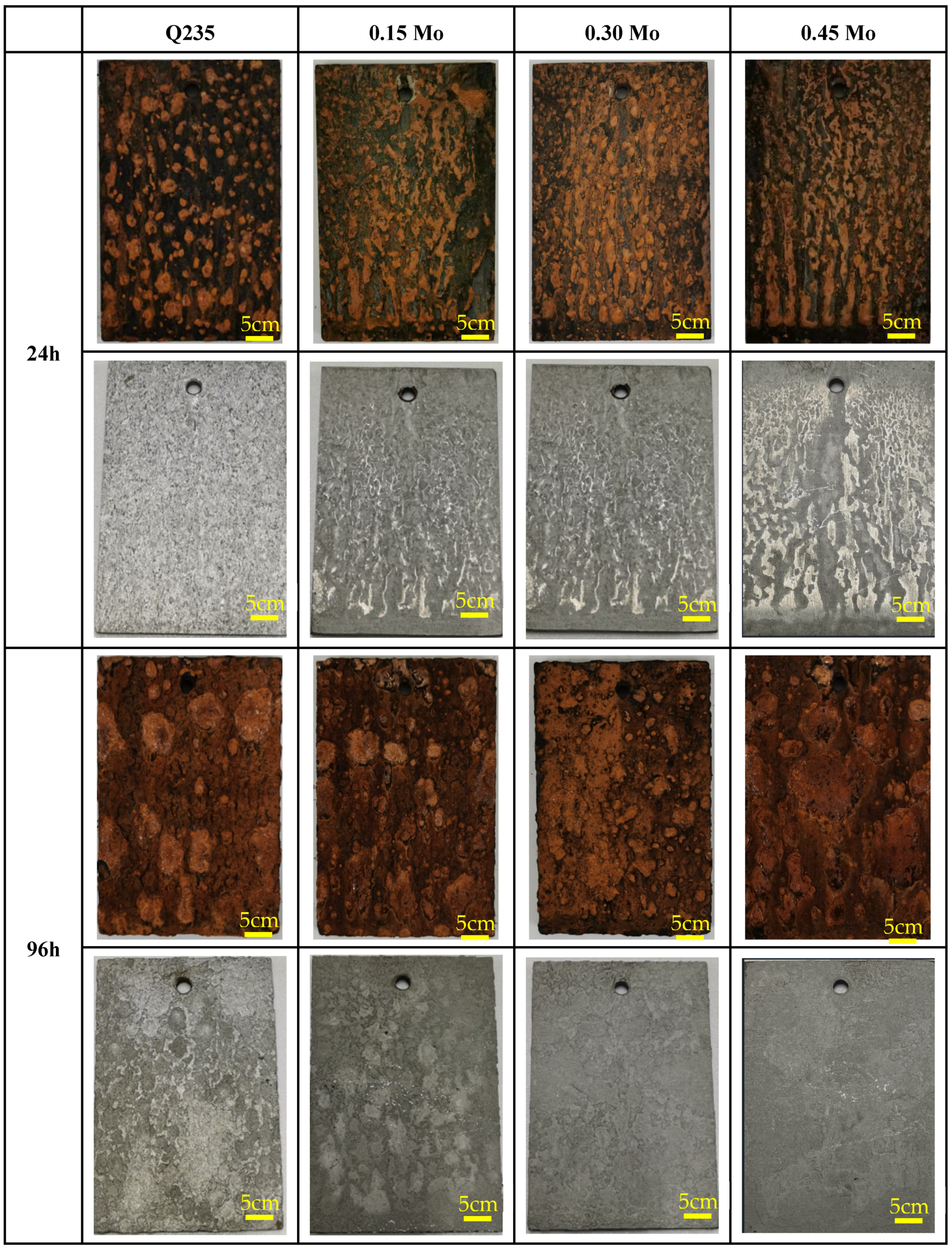
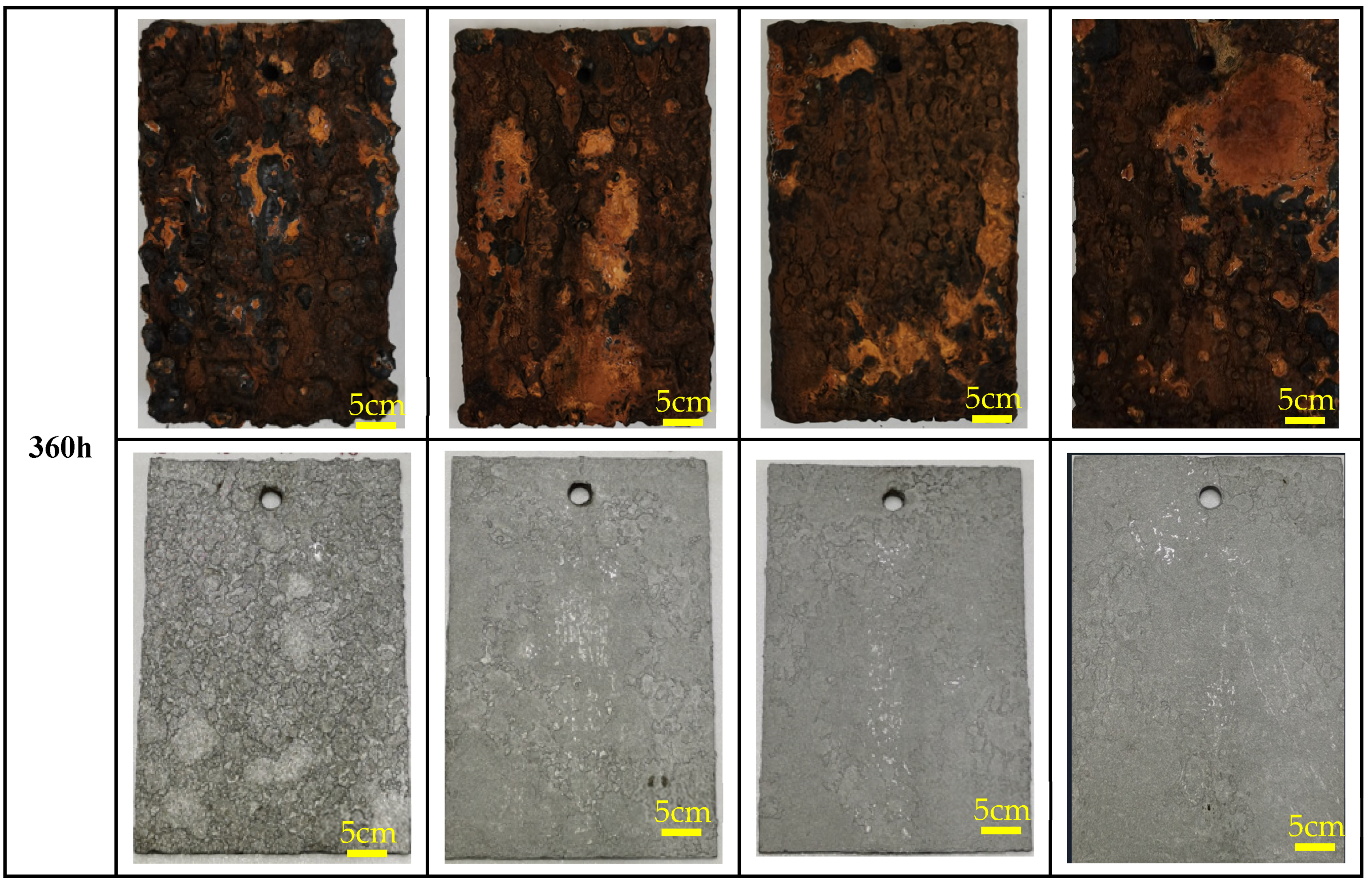
3.2. Macroscopic Studies of Corrosion Products

Figure 3 presents the macroscopic topographical features of four specimens exposed to simulated marine atmospheric conditions. As a previous study indicated, we can preliminarily judge the corrosion resistance of WS depending on the surface morphology [17]. The colors of the rust layer are orange, brown, and black, indicating that the protection ability is low, high, and subject to a loss of protection, respectively. In the initial corrosion process, the surface morphology of Q235 is covered by orange rust layer with lots of dark spots. As the corrosion process prolonged, the surface morphology of Q235 is almost covered by the dark rust layer, which means the rust layer is not equipped with the protection capability. However, the surface morphologies of 0.15Mo, 0.30Mo, and 0.45Mo are covered by orange rust layer with areas of dark spots in the early corrosion process. In the later corrosion process, these rust layers transform into a brown rust layer with areas of cracking, which indicates the rust layer has some protection capability. In addition, after removing the rust layer, a large number of corrosion pits appeared on the surface of Q235 at the later stage of corrosion. However, the surface of the other three WS variants was relatively flat, and the corrosion pits decreased with the increase in the Mo content. This observation corroborates that Mo concentrations within an optimal threshold enhance the corrosion resistance of 1%Ni WS, aligning with corrosion kinetic results.

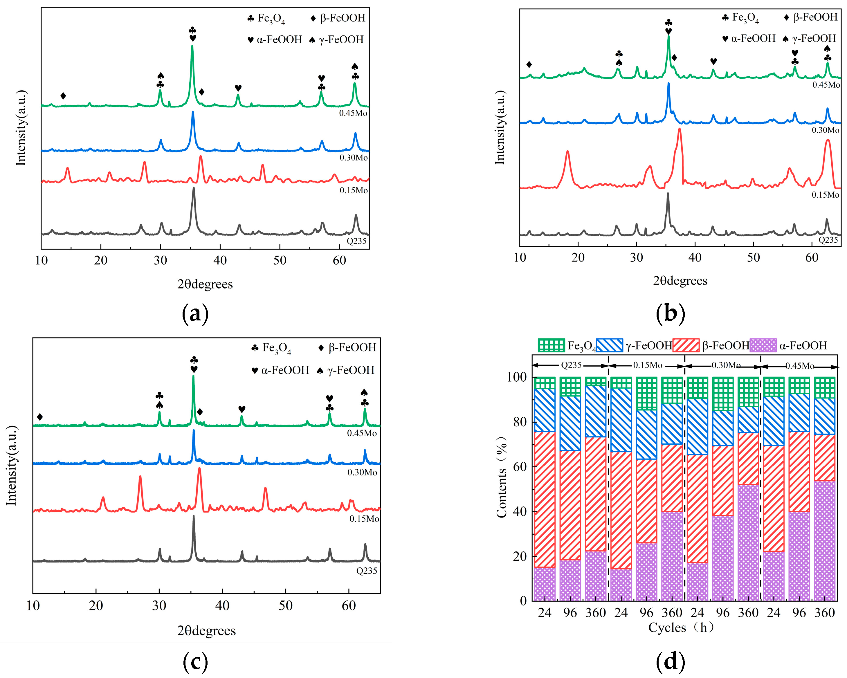
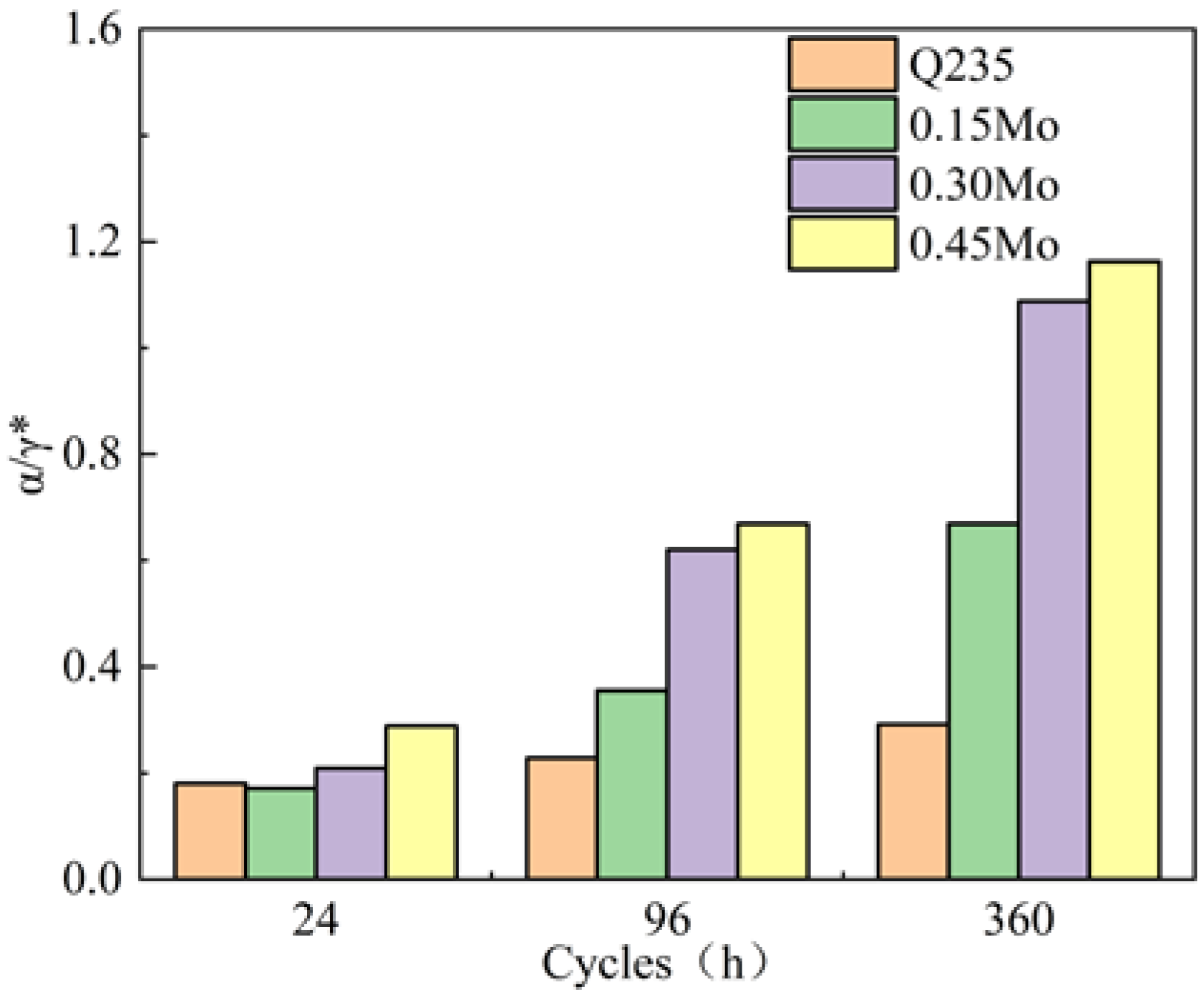
3.3. Composition of the Rust Layer

The XRD analysis revealed a phase evolution in corrosion products from four steel variants exposed to simulated marine atmospheric conditions. All specimens exhibited characteristic peaks corresponding to γ-FeOOH, β-FeOOH, α-FeOOH, and Fe3O4, with compositional variations quantified through combined reference intensity ratio (RIR) and a Rietveld refinement analysis [18]. As shown in Figure 4, the initial corrosion phases exhibited γ-FeOOH/β-FeOOH dominance (75–82% cumulative phase fraction), while prolonged exposure triggered phase redistribution favoring α-FeOOH (18–26% increase) and magnetite formation (12–18% gain) accompanied by 30–40% reduction in metastable oxyhydroxides. Notably, α-FeOOH content demonstrated a linear correlation with Mo alloying (R2 = 0.89), indicating molybdenum’s catalytic role in stabilizing goethite formation—a phenomenon consistent with prior studies on transition metal-modified corrosion systems [19,20].
The Jade6.0 software program was used to calculate the relative content of the phase structure of the corrosion products according to RIR and Rietveld calculation methods. The protective capacity of corrosion products was evaluated through the α/γ* ratio (α-FeOOH/[γ-FeOOH + β-FeOOH + Fe3O4]), where values exceeding unity indicate protective rust formation [18]. Initial exposure data (Figure 5) revealed subcritical α/γ* ratios for Q235 (0.18), 0.15Mo (0.17), 0.30Mo (0.20), and 0.45Mo (0.28), confirming non-protective oxide layers. Subsequent corrosion stages demonstrated significant phase evolution, with ratios increasing to 0.29 (Q235), 0.67 (0.15Mo), 1.08 (0.30Mo), and 1.16 (0.45Mo). This progression highlights molybdenum’s synergistic effect with nickel in promoting protective α-FeOOH stabilization. Notably, alloys containing ≥0.30% Mo exhibited comparable α/γ* values (Δ = 0.08), suggesting optimal molybdenum efficacy within 0.30–0.45% concentration range for 1% nickel weathering steel in marine atmospheric environments. These phase distribution trends correlate strongly with mass loss data from corrosion kinetic studies.

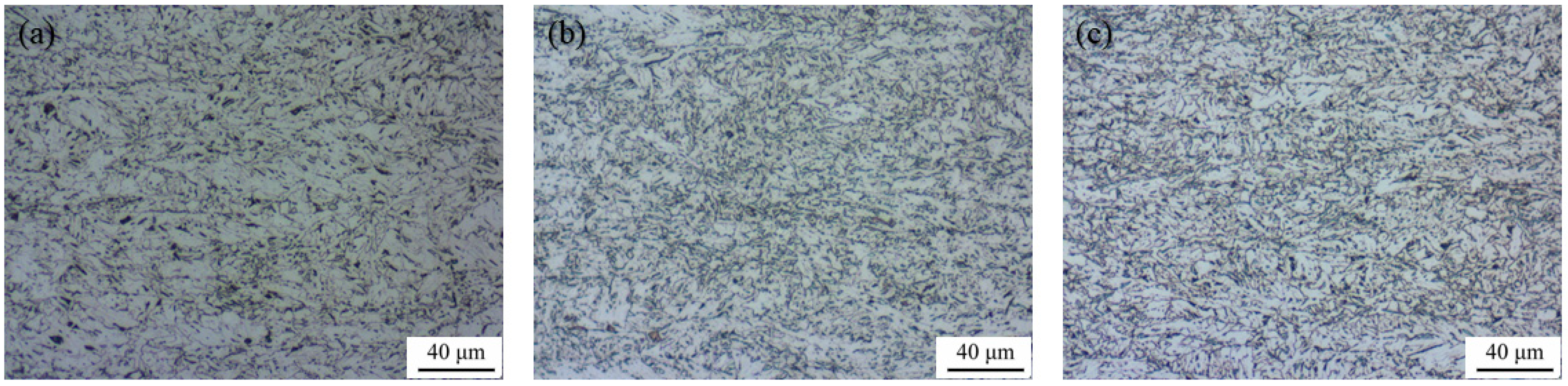
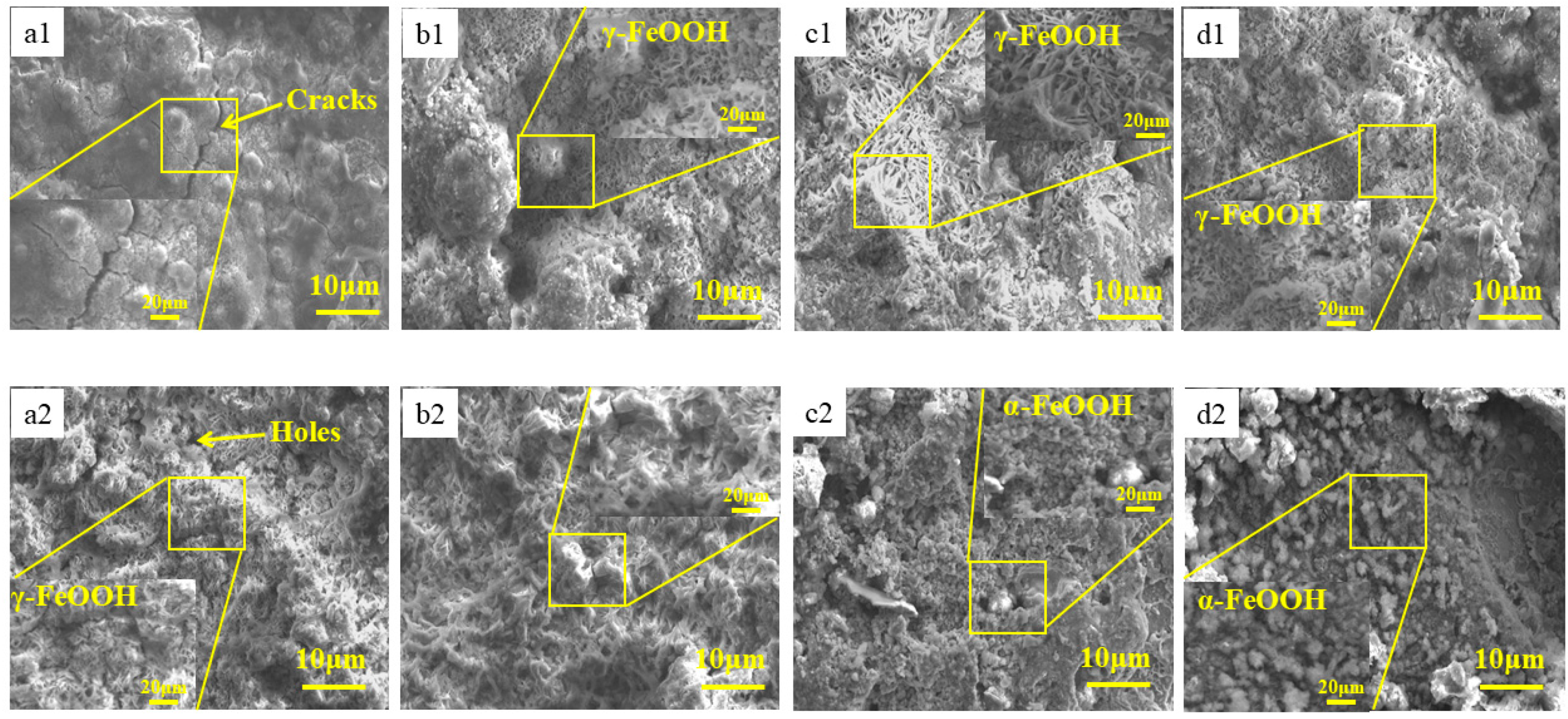
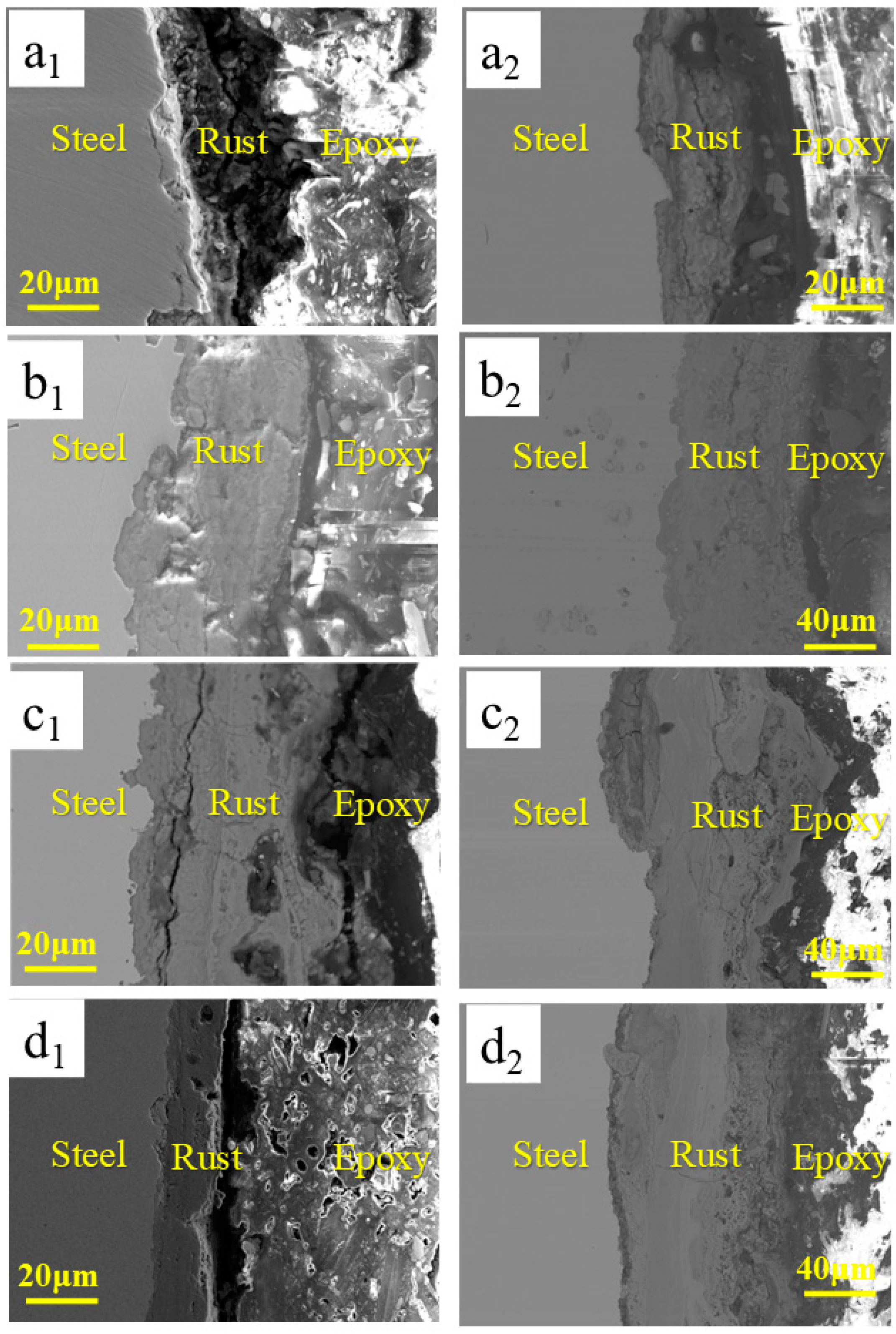
3.4. Microstructure Studies of Corrosion Products

Figure 6 presents the microstructural characteristics of four experimental specimens exposed to simulated marine atmospheric conditions at various corrosion stages. At the initial stage of corrosion, the surface of the rust layer on the Q235 sample exhibits numerous cracks and pores, which permit corrosion particles to penetrate easily and lead to an accelerated corrosion rate. Although the surfaces of the rust layers of 0.15Mo, 0.30Mo, and 0.45Mo WS possess a small quantity of cracks and holes, they contain a large number of feather-shaped and rosette-like structures, which signify γ-FeOOH and β-FeOOH, respectively [21,22]. γ-FeOOH and β-FeOOH represent unstable phase structures with an open configuration, allowing corrosion particles to enter effortlessly and resulting in a high corrosion rate.
As the corrosion process advances, a cotton-ball-like structure (α-FeOOH), indicating a stable phase structure, emerges on the surfaces of 0.30Mo and 0.45Mo WS [23]. A significant accumulation of cotton-ball-like structures on the surface of the rust layer renders it uniform and dense, which obstructs the passage of corrosion particles through the rust layer and reduces the corrosion rate. Simultaneously, it is observable that the pores diminish remarkably as the corrosion process continues, suggesting that the addition of Mo can repair the holes in the later stage of corrosion. Additionally, Mo incorporation promotes the formation of α-FeOOH in greater quantities and increases the compactness of the corrosion product layer, thereby augmenting the material’s resistance to marine atmospheric. corrosion.
Figure 7 illustrates the cross-sectional microstructural features of four experimental specimens exposed to simulated marine atmospheric conditions. Microscopic analysis reveals that all samples exhibit varying degrees of cracking and, in severe cases, delamination from the underlying substrate within their corrosion product layers, indicating ineffective protective functionality. With increasing corrosion duration, Mo alloying induces notable improvements in cross-sectional morphologies. Specifically, 0.30 wt% Mo and 0.45 wt% Mo variants develop denser, more homogeneous oxide layers that form a physical barrier, thereby retarding corrosive penetration. This microstructural evolution represents the primary mechanism responsible for the observed corrosion rate reduction during advanced corrosion stages.

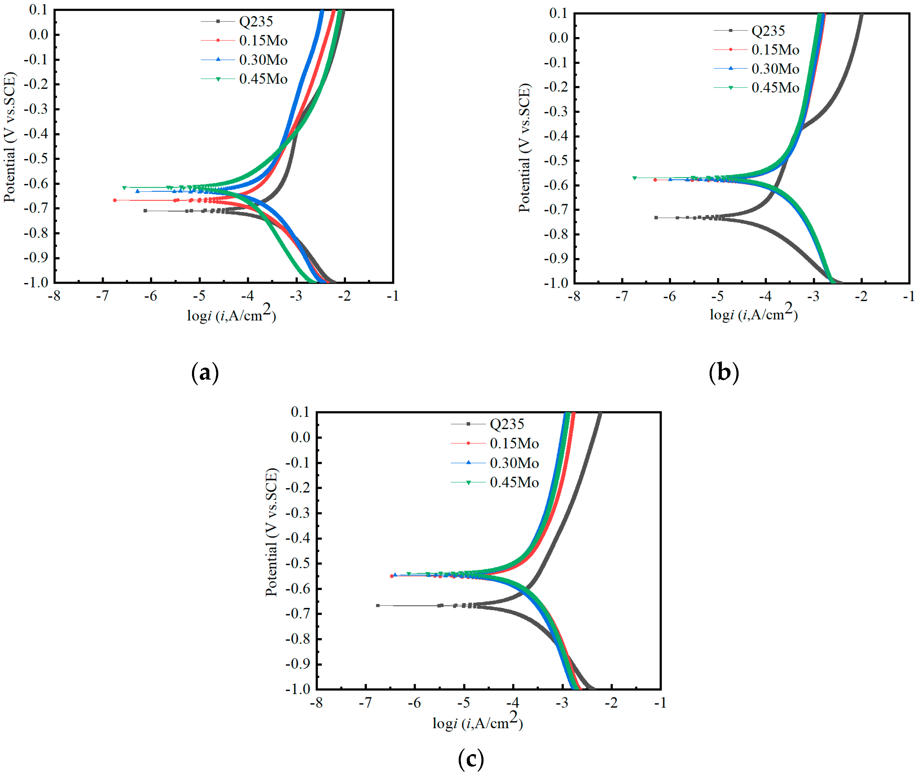
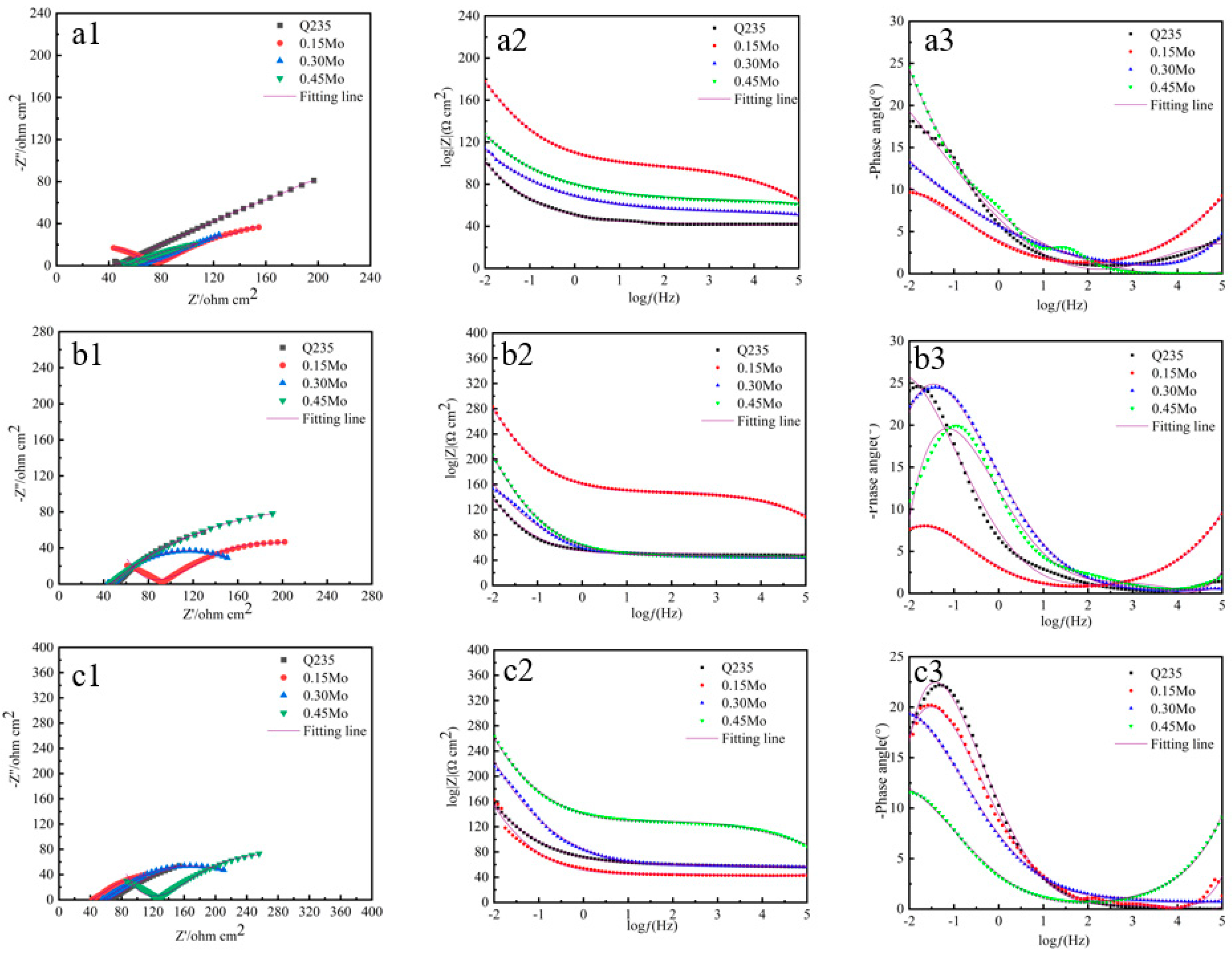
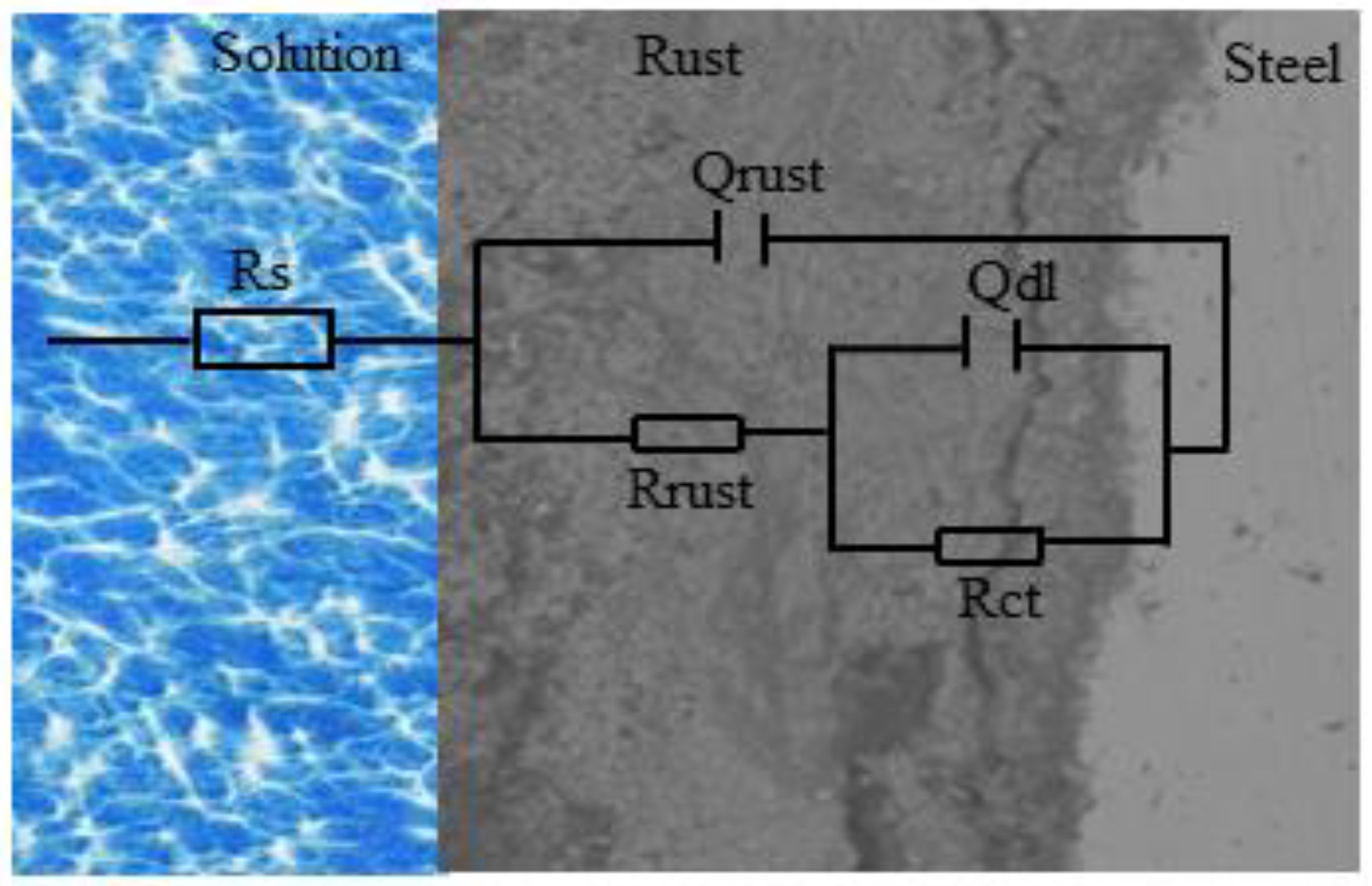
3.5. Electrochemical Properties of the Rust Layer

Figure 8 shows the Tafel plots of the four test samples in the simulated marine atmospheric environment during the corrosion process. All the Tafel curves share similarities, indicating that the electrochemical mechanisms of the four test samples were mostly the same [24]. The parameters of Tafel curve were calculated by the extrapolation method, as shown in Table 3. These parameters characterize the corrosion mechanisms and kinetic behaviors, serving as key electrochemical corrosion metrics. The anodic reactions were primarily governed by metal dissolution, while the cathodic reactions were controlled by the reduction in corrosion products and oxygen [25].
Electrochemical monitoring revealed a systematic positive shift in corrosion potential coupled with current density reduction as molybdenum concentration rose through successive corrosion cycles. This progression denotes enhanced protective characteristics over extended durations. Phase composition modifications identified through XRD characterization demonstrated proportional α-FeOOH enrichment corresponding to elevated Mo levels in the oxide matrix. According to Hedensted et al. [26], who examined the hydrogen evolution reaction kinetics of α-FeOOH and γ-FeOOH phases, α-FeOOH exhibits a more positive corrosion potential compared to γ-FeOOH. This finding explains the observed positive shift in corrosion potential with increasing Mo content, which enhances the protective properties of the rust layer. A polarization curve analysis further validated that Mo alloying in 1%Ni WS significantly improves the corrosion resistance of corrosion products. This improvement is primarily attributed to the preferential formation of α-FeOOH, which elevates the corrosion potential and reduces the corrosion current density through its superior protective characteristics.
Electrochemical impedance spectroscopy (EIS) measurements were performed, as presented in Figure 9. Previous investigations have demonstrated that with prolonged corrosion exposure, the charge transfer resistance of weathering steel (WS) corrosion product layers increases progressively, leading to incremental improvements in protective performance. Notably, Mo-alloyed steels, particularly the 0.30 wt% Mo and 0.45 wt% Mo variants, exhibit superior densification and corrosion resistance enhancements within their oxide layers. Figure 9(a2,b2,c2,a3,b3,c3) display Bode plots for the four experimental specimens at different corrosion stages, including impedance modulus and phase angle diagrams. These graphical representations reveal maximum phase angles below 90°, indicating non-ideal capacitive responses within the corrosion products. Such deviations from ideal capacitive behavior can be attributed to porous characteristics, mass transport phenomena, and relaxation processes occurring within the corrosion layers [19,27]. The EIS results offer significant insights into the temporal evolution of the rust layer’s electrochemical attributes. Specifically, the escalating charge transfer resistance suggests that the protective efficacy of the corrosion product layer improves as corrosion progresses. The superior performance of Mo-alloyed steels highlights the critical role of Mo in facilitating the formation of a denser, more protective oxide layer, thereby substantially enhancing corrosion resistance.
Based on the EIS test results, a fitted equivalent circuit model was developed for the electrochemical impedance spectra, as depicted in Figure 10. The circuit components are defined as follows: Qrust and Rrust correspond to the constant phase elements and resistors associated with the corrosion product layer; Rs represents the solution resistance between the reference electrode and working electrode; Qdl denotes the constant phase element of the electrochemical double layer; and Rct signifies the charge transfer resistance at the metal-electrolyte interface [28]. RS encompasses not only the reactive impedance but also the physical impedance within the entire testing system. This includes impedances from the electrolytic cell system, those arising from connections to the electrochemical workstation (contact impedance), and wire impedances. Variations in the number of ions present in the solution can influence the value of RS. Given the rough, porous, and heterogeneous characteristics of the corrosion product layer surface, the electrochemical double-layer capacitance deviates from ideal capacitive behavior. Consequently, constant phase elements (CPEs) denoted as Qrust and Qdl are employed to characterize the double-layer capacitance, accounting for surface irregularities and system inhomogeneity induced by corrosion processes. This modeling approach effectively captures the topological non-uniformity arising from complex electrochemical reactions at the metal/electrolyte interface. The use of constant phase elements (CPEs) like Qrust and Qdl is particularly important because they better capture the non-ideal behavior of the corrosion interface. Traditional capacitors assume a perfectly flat and homogeneous surface, which is not representative of real-world corrosion scenarios. By incorporating CPEs, the equivalent circuit more accurately models the impedance behavior observed in practical corrosion systems, providing a more reliable interpretation of the electrochemical processes involved.
The electrochemical parameters derived from EIS measurements for corrosion product layers at different exposure durations are tabulated in Table 4, with fitting errors below 10−4. The phase shift coefficient (N), representing non-ideal capacitive behavior, reflects the surface heterogeneity induced by topological irregularities, metal dissolution, impurity segregation, active site distribution, inhibitor adsorption, or porous layer formation. The data analysis reveals that both corrosion product resistance (Rrust) and charge transfer resistance (Rct) increase with prolonged corrosion exposure. This trend signifies the progressive development of barrier properties within the oxide film, augmenting the overall resistivity of the corrosion product layer. Consequently, elevated resistance values indicate improved corrosion protection efficiency by impeding corrosive ion penetration [7,29]. Notably, Mo-alloyed WS variants exhibit significantly higher Rct and Rrust compared to Q235 steel, confirming that Mo additions enhance both the corrosion product film resistivity and charge transfer resistance of 1%Ni WS. Specifically, Mo-containing steels demonstrate superior protective characteristics, which contribute to time-dependent improvements in corrosion resistance. Collectively, these EIS results highlight the efficacy of Mo in enhancing the barrier properties and charge transfer resistance of corrosion product layers, thereby providing superior overall corrosion protection for weathering steels.

4. Discussion

According to the above results, the corrosion mechanism of containing Mo 1Ni WS is shown in Figure 11. Based on the findings presented in references [4,30], nickel demonstrates significant potential in improving corrosion resistance within marine atmospheric environments when present at concentrations exceeding 3%. The mechanism involves a dual reaction pathway where nickel atoms initially oxidize through interactions with atmospheric moisture and oxygen to form nickel hydroxide (Ni(OH)2). Subsequent transformations of this hydroxide product occur through two distinct processes: a fraction undergoes hydrolytic decomposition under ambient humidity conditions to yield nickel oxide (NiO), while another portion participates in a substitution reaction with Fe2+ ions in iron(II, III) oxide (Fe3O4) lattice structures, resulting in the formation of nickel ferrite (NiFe2O4) with a spinel crystal structure. This nanoscale compound plays a critical role in facilitating the thermodynamically favorable phase transition of γ-FeOOH to its more stable α-FeOOH polymorph. The detailed chemical processes can be described as follows: [29]:
2 Ni + O 2 + 2 H 2 O   2 Ni ( OH ) 2
Ni ( OH ) 2 NiO + H 2 O
Ni ( OH ) 2 + 2 Fe ( OH ) 2 Ni Fe 2 O 4 + 3 H 2 O
According to refs. [30,31], the octahedral sites within the Fe3O4 crystalline lattice can accommodate Ni2+ cations through isomorphous substitution, resulting in the formation of a spinel-structured NiFe2O4 phase. This cationic substitution creates abundant nucleation loci for both γ-FeOOH and α-FeOOH polymorphs, thereby promoting the thermodynamically favorable transformation of metastable γ-FeOOH into its nanocrystalline α-FeOOH counterpart. Moreover, this process induces the development of an electronegative rust layer within the corrosion product matrix, which establishes a physical barrier against chloride ion penetration and significantly improves the atmospheric corrosion resistance of WS.
Consequently, the addition of Ni to WS may significantly improve its corrosion resistance compared to ordinary weathering steel in marine atmospheric environments. From a cost perspective, moderately reducing the Ni content remains feasible. However, excessive reduction could compromise the corrosion resistance necessary for meeting service requirements in such environments.
Experimental results further demonstrated that adding Mo to 1%Ni WS enhances corrosion resistance in marine atmospheric conditions. A morphological analysis of the corrosion products confirmed that Mo effectively decreased the diameter of holes and cracks in the rust layer, as shown in Figure 6. This suggests that the Mo element contributes to repairing and densifying the rust layer, thereby improving its protective properties.
The relevant reactions involving Mo elements, as reported in the literature, are summarized below: Mo can promote the formation of protective phases within the rust layer, contributing to its densification. The presence of Mo enhances the stability of α-FeOOH, leading to a more uniform and protective rust layer. Mo reduces the size and number of defects in the rust layer, minimizing pathways for corrosive ions to penetrate. As reported in refs. [6,10,32], the relevant reactions involving Mo elements are as follows:
Mo + O 2 + 2 H 2 O   Mo ( OH ) 4 + 1 / 2 H 2 O   +   H 2 O Mo ( OH ) 6
Mo ( OH ) 4 Mo O 2 + 2 H 2 O   ( Hydrolysis )
Mo ( OH ) 6 Mo O 3 + 3 H 2 O   ( Hydrolysis )
As illustrated in Figure 4, increasing molybdenum content correlates with a proportional rise in α-FeOOH formation. The Mo dopant acts as a nucleation promoter for amorphous oxyhydroxide phases, inducing the development of an interconnected nanoscale oxyhydroxide network. This structural arrangement serves a dual function: it physically entraps corrosive species while simultaneously providing preferential sites for α-FeOOH crystallization. The resultant corrosion product layer forms a compact physical barrier with enhanced protective properties against environmental degradation [33]. Meanwhile, the research indicated that the Mo element was always close to the Ni element due to the NiFe2O4 being equipped with electronegativity. The NiFe2O4 could adsorb the Mo ions, and then the Mo participates in hydrolysis through reaction (4)–(6). The generation of MoO2 and MoO3 will fill up the cracks and holes, as observed in Figure 6, making the rust layer more compact and uniform. However, the results show that when the Mo content is higher than 0.30, the corrosion rate does not decrease significantly. This may be because it is difficult for the excessive Mo ions to migrate around the Ni element completely. As a result, only some of the Mo ions can migrate to the vicinity of the Ni element for the hydrolysis reaction, which makes it hard to improve the corrosion rate of the steel with a high Mo content. Hence, the content of the Mo element can be controlled at 0.3–0.5% for the 1Ni weathering steel.

5. Conclusions

(1)
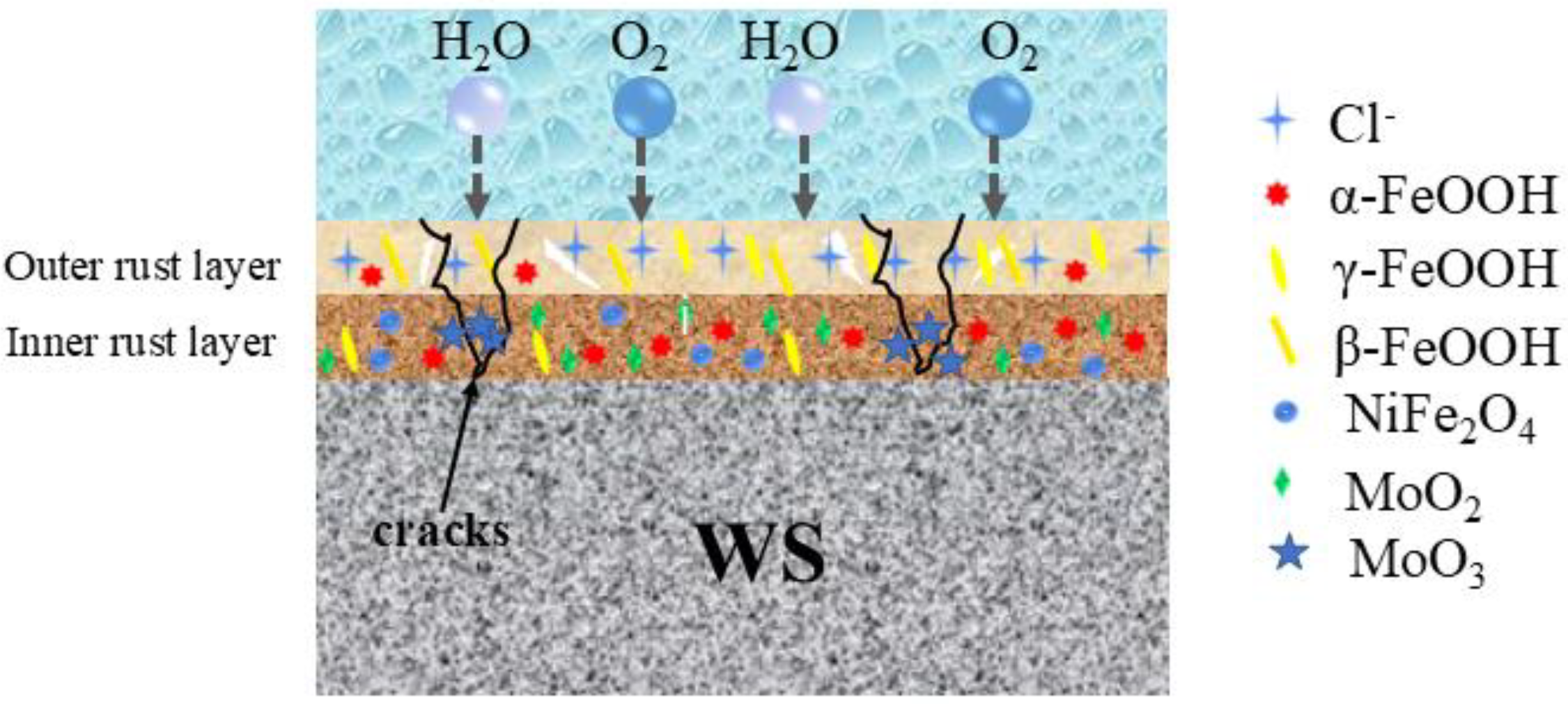
Adding a specific amount of Mo to 1%Ni weathering steel (WS) significantly enhances its corrosion resistance. The increasing Mo content promotes the formation of a stable and compact rust layer, which markedly increases the proportion of α-FeOOH. This transformation endows the rust layer with effective physical barrier properties, thereby providing superior protection against corrosion.
(2)
The presence of Mo leads to the formation of MoO2 and MoO3 deposits within the holes and cracks of the rust layer. These deposits serve multiple functions. Compaction and Uniformity: They make the rust layer more compact and uniform. Trapping Corrosive Particles: They trap corrosive particles, preventing further penetration. Promotion of α-FeOOH Formation: They facilitate the formation of α-FeOOH, which contributes to the rust layer’s protective ability by forming a physical barrier.
(3)
Only some of the Mo ions migrate to the vicinity of the Ni element for the hydrolysis reaction, which led to the difficultly in improving the corrosion rate of the steel with a high Mo content. Hence, the content of the Mo element can be controlled at 0.3–0.5% for the 1Ni WS.

Author Contributions

Conceptualization, Q.W.; methodology, Q.W. and C.H.; software, Q.Y. and M.Q.; validation, S.W.; formal analysis, S.W.; investigation, Q.Y.; resources, Q.W. and M.Q.; data curation, Q.Y. and M.Q.; writing—original draft preparation, Q.W. and C.H.; writing—review and editing, Q.W. and C.H.; visualization, Q.W.; supervision, Q.W.; project administration, Q.W. All authors have read and agreed to the published version of the manuscript.

Funding

This research was funded by the Development Program between Nanjing Iron & Steel Co., Ltd. and Yanshan University (Grant No. IG A B21090004), the Cangzhou Natural Science Foundation (Grant No. 221001012D), and the Scientific Research and Innovation Project of Cangzhou Normal University (Grant No. cxtdl2301).

Data Availability Statement

The original contributions presented in this study are included in the article. Further inquiries can be directed to the corresponding author.

Conflicts of Interest

Author Mingliang Qiao was employed by Nanjing Iron & Steel Co., Ltd. The remaining authors declare that the research was conducted in the absence of any commercial or financial relationships that could be construed as a potential conflict of interest. Besides, the authors declare that this study received funding from Nanjing Iron & Steel Co., Ltd. The funder was not involved in the study design, collection, analysis, interpretation of data, the writing of this article or the decision to submit it for publication.

References

  1. Jia, J.; Cheng, X.; Yang, X.; Li, X.; Li, W. A study for corrosion behavior of a new-type weathering steel used in harsh marine environment. Constr. Build. Mater. 2020, 259, 119760. [Google Scholar] [CrossRef]
  2. Morcillo, M.; Chico, B.; Diaz, I.; Cano, H.; Fuente, D.D.L. Atmospheric corrosion data of weathering steels. A review. Corros. Sci. 2013, 77, 6–24. [Google Scholar] [CrossRef]
  3. Wu, W.; Cheng, X.; Zhao, J.; Li, X. Benefit of the corrosion product film formed on a new weathering steel containing 3% nickel under marine atmosphere in Maldives. Corros. Sci. 2019, 165, 108416. [Google Scholar] [CrossRef]
  4. Zhang, B.; Liu, W.; Sun, Y.; Yang, W.; Chen, L.; Xie, J.; Li, W. Corrosion behavior of the 3 wt% Ni weathering steel with replacing 1 wt% Cr in the simulated tropical marine atmospheric environment. J. Phys. Chem. Solids 2023, 175, 111221. [Google Scholar] [CrossRef]
  5. Diaz, I.; Cano, H.; Fuente, D.D.L.; Chico, B.; Vega, J.M.; Morcillo, M. Atmospheric corrosion of Ni-advanced weathering steels in marine atmospheres of moderate salinity. Corros. Sci. 2013, 76, 348–360. [Google Scholar] [CrossRef]
  6. Usami, A.; Kihira, H.; Kusunoki, T. 3%Ni Weathering Steel Plate for Uncoated Bridges at High Airborne Salt Environment. Shinnittetsu Giho 2003, 19–21. Available online: https://www.nipponsteel.com/en/tech/report/nsc/pdf/n8706.pdf (accessed on 1 April 2025).
  7. Yu, Q.; Yang, X.; Dong, W.; Wang, Q.; Zhang, F.; Gu, X. Layer-by-layer investigation of the multilayer corrosion products for different Ni content weathering steel via a novel Pull-off testing. Corros. Sci. 2022, 195, 109988. [Google Scholar] [CrossRef]
  8. Jia, J.; Liu, Z.; Cheng, X.; Du, C.; Li, X. Development and optimization of Ni-advanced weathering steel: A review. Corros. Commun. 2021, 2, 82–90. [Google Scholar] [CrossRef]
  9. Cheng, X.; Jin, Z.; Liu, M.; Li, X. Optimizing the nickel content in weathering steels to enhance their corrosion resistance in acidic atmospheres. Corros. Sci. 2017, 115, 135–142. [Google Scholar] [CrossRef]
  10. Zhu, C.; Gao, X.; Zhu, C.; Li, W.; Liu, T.; Du, L.; Wu, H. A study on corrosion behavior of advanced weathering steel relying on Ni–Mo synergy under marine atmosphere. J. Mater. Res. Technol. 2024, 30, 8469–8481. [Google Scholar] [CrossRef]
  11. Xu, X.; Zhang, T.; Wu, W.; Jiang, S.; Yang, J.; Liu, Z. Optimizing the resistance of Ni-advanced weathering steel to marine atmospheric corrosion with the addition of Al or Mo. Constr. Build. Mater. 2021, 279, 122341. [Google Scholar] [CrossRef]
  12. Nishimura, T.; Kodama, T. Clarification of chemical state for alloying elements in iron rust using a binary-phase potential–pH diagram and physical analyses. Corros. Sci. 2003, 45, 1073–1084. [Google Scholar] [CrossRef]
  13. Hao, L.; Zhang, S.; Dong, J.; Ke, W. A study of the evolution of rust on Mo–Cu-bearing fire-resistant steel submitted to simulated atmospheric corrosion. Corros. Sci. 2012, 54, 244–250. [Google Scholar] [CrossRef]
  14. Teramoto, K.H.A. An X-ray photo-electron spectroscopic study on the role of molybdenum in increasing the corrosion resistance of ferritic stainless steels in HC1. Corros. Sci. 1979, 19, 3–14. [Google Scholar]
  15. Sun, Y.; Liu, W.; Dong, B.; Zhang, T.; Chen, L.; Yang, W.; Li, H.; Zhang, B.; Xie, J.; Cui, J. Designing Weathering Steel with Optimized Mo/Ni Ratios for Better Corrosion Resistance in Simulated Tropical Marine Atmosphere. Met. Mater. Int. 2024, 30, 909–927. [Google Scholar] [CrossRef]
  16. TB/T 2375-1993 (1993); Test Method for Periodic Immersion Corrosion of Weathering Steels for Railway. Ministry of Railways: Beijing, China, 1993.
  17. Wang, B.; Liu, L.; Cheng, X.; Wu, W.; Liu, C.; Zhang, D.; Li, X. Advanced multi-image segmentation-based machine learning modeling strategy for corrosion prediction and rust layer performance evaluation of weathering steel. Corros. Sci. 2024, 237, 112334. [Google Scholar] [CrossRef]
  18. Kamimura, T.; Hara, S.; Miyuki, H.; Yamashita, M.; Uchida, H. Composition and protective ability of rust layer formed on weathering steel exposed to various environments. Corros. Sci. 2006, 48, 2799–2812. [Google Scholar] [CrossRef]
  19. Cano, H.; Neff, D.; Maricllo, M.; Dillmann, P.; Diaz, I.; de la Fuente, D. Characterization of corrosion products formed on Ni 2.4 wt%-Cu 0.5 wt%-Cr 0.5 wt% weathering steel exposed in marine atmospheres. Corros. Sci. 2014, 87, 438–451. [Google Scholar] [CrossRef]
  20. Zhang, T.; Liu, W.; Chen, L.; Dong, B.; Yang, W.; Fan, Y.; Zhao, Y. On how the corrosion behavior and the functions of Cu, Ni and Mo of the weathering steel in environments with different NaCl concentrations. Corros. Sci. 2021, 192, 109851. [Google Scholar] [CrossRef]
  21. Antunes, R.A.; Costa, I.; Faria, D.L.A.D. Characterization of corrosion products formed on steels in the first months of atmospheric exposure. Mater. Res. 2003, 6, 403–408. [Google Scholar] [CrossRef]
  22. Yu, Q.; Dong, W.; Yang, X.; Wang, Q.; Zhang, F. Insights into the corrosion mechanism and electrochemical properties of the rust layer evolution for weathering steel with various Cl deposition in the simulated atmosphere. Mater. Res. Express 2021, 8, 36515–36518. [Google Scholar] [CrossRef]
  23. Liu, H.; Huang, F.; Yuan, W.; Hu, Q.; Liu, J.; Cheng, Y.F. Essential role of element Si in corrosion resistance of a bridge steel in chloride atmosphere. Corros. Sci. 2020, 173, 108758. [Google Scholar] [CrossRef]
  24. Mansfeld, F. Tafel slopes and corrosion rates obtained in the pre-Tafel region of polarization curves. Corros. Sci. 2005, 47, 3178–3186. [Google Scholar] [CrossRef]
  25. Mccafferty, E. Validation of corrosion rates measured by the Tafel extrapolation method. Corros. Sci. 2005, 47, 3202–3215. [Google Scholar] [CrossRef]
  26. Hedenstedt, K.; Simic, N.; Wildlock, M.; Ahlberg, E. Kinetic study of the hydrogen evolution reaction in slightly alkaline electrolyte on mild steel, goethite and lepidocrocite. J. Electroanal. Chem. 2016, 783, 1–7. [Google Scholar] [CrossRef]
  27. Yu, Q.; Dong, W.; Yang, X.; Wang, Q.; Zhang, F. The Role of the Direct Current Electric Field in Enhancing the Protective Rust Layer of Weathering Steel. J. Mater. Eng. Perform. 2021, 30, 6309–6322. [Google Scholar] [CrossRef]
  28. Chen, Z.; Yu, Q.; Zhao, L.; Zhang, C.; Gu, M.; Wang, Q.; Wang, G. Insight into the role of Si on corrosion resistance of weathering steel in a simulated industrial atmosphere. J. Mater. Res. Technol. 2023, 26, 487–503. [Google Scholar] [CrossRef]
  29. Hao, L.; Zhang, S.; Dong, J.; Ke, W. Atmospheric corrosion resistance of MnCuP weathering steel in simulated environments. Corros. Sci. 2011, 53, 4187–4192. [Google Scholar] [CrossRef]
  30. Wu, W.; Cheng, X.; Hou, H.; Liu, B.; Li, X. Insight into the product film formed on Ni-advanced weathering steel in a tropical marine atmosphere. Appl. Surf. Sci. 2018, 436, 80–89. [Google Scholar] [CrossRef]
  31. Wu, W.; Dai, Z.; Liu, Z.; Liu, C.; Li, X. Synergy of Cu and Sb to enhance the resistance of 3%Ni weathering steel to marine atmospheric corrosion. Corros. Sci. 2021, 183, 109353. [Google Scholar] [CrossRef]
  32. Niu, G.; Yuan, R.; Wang, E.; Yang, X.; Liu, Z.; Li, Z.; Zhang, Z.; Gong, N.; Li, K.; Su, B. Unraveling the influence of Mo on the corrosion mechanism of Ni-advanced weathering steel in harsh marine atmospheric environments. J. Mater. Sci. Technol. 2024, 195, 41–62. [Google Scholar] [CrossRef]
  33. Kimura, M.; Kihira, H.; Ohta, N.; Hashimoto, M.; Senuma, T. Control of Fe(O,OH)6 nano-network structures of rust for high atmospheric-corrosion resistance. Corros. Sci. 2005, 47, 2499–2509. [Google Scholar] [CrossRef]
Figure 1. The microstructure of WS. (a) 0.15Mo; (b) 0.30Mo; (c) 0.45Mo.
Metals 15 00430 g001
Figure 2. The weight loss diagram (a); the corrosion rate diagram (b).
Metals 15 00430 g002
Figure 3. The surface topographies of four experimental specimens exposed to simulated marine atmospheric conditions.
Metals 15 00430 g003aMetals 15 00430 g003b
Figure 4. The XRD patterns of four experimental specimens exposed to simulated marine atmospheric conditions. Subfigure (a) displays the 24 h corrosion products, (b) the 96 h reaction layer, (c) the 360 h oxidation structure, and (d) the phase composition quantification within the corrosion product layers.
Metals 15 00430 g004
Figure 5. The corrosion-protective performance evaluation of four experimental specimens exposed to simulated marine atmospheric conditions.
Metals 15 00430 g005
Figure 6. The microscopic morphology of four test samples. (a1,b1,c1,d1) refer to 24 h; (a2,b2,c2,d2) refer to 96 h; (a) Q235; (b) 0.15Mo; (c) 0.30 Mo; (d) 0.45 Mo.
Metals 15 00430 g006
Figure 7. The cross-sectional microscopic morphology of four test samples in the simulated marine atmospheric environment. (a1,b1,c1,d1) refer to 24 h; (a2,b2,c2,d2) refer to 360 h; (a) Q235; (b) 0.15v; (c) 0.30 Mo; (d) 0.45 Mo.
Metals 15 00430 g007
Figure 8. The Tafel plots of the four test samples in the simulated marine atmospheric environment. (a) After 24 h; (b) after 96 h; (c) after 360 h.
Metals 15 00430 g008
Figure 9. The EIS plot of four test samples in the simulated marine atmospheric environment (a1,b1,c1), Nyquist plots (a2,b2,c2), and (a3,b3,c3) Bode plots for the different corrosion time periods. (a) 24 h; (b) 96 h; (c) 360 h.
Metals 15 00430 g009
Figure 10. Electrochemical equivalent circuits of the rust layer.
Metals 15 00430 g010
Figure 11. Mechanism diagram of containing Mo 1Ni WS.
Metals 15 00430 g011
Table 1. Chemical compositions of the test samples.
SteelCSiMnPSNiMoCuFe
Q2350.1500.220.640.0030.003---Balance
0.15Mo0.0530.200.920.0030.0021.300.160.59Balance
0.30Mo0.0460.210.890.0030.0031.330.290.55Balance
0.45Mo0.0520.200.900.0030.0031.300.450.58Balance
Table 2. Parameters of wet–dry cyclic corrosion test.
-Experimental Parameters
Solution35 g/L ± 1 g/L (3.5%NaCl solution)
pH7.5–8.2
Temperature45 ± 2 °C
Relative humidity70 ± 5%RH
Cycle time60 ± 3 min, infiltration time 12 ± 1.5 min
Test period24 h, 96 h, 168 h, 216 h, 360 h
Reference standardTB/T 2375-1993
Table 3. Tafel curve parameters with the four test samples.
SamplesEcorr/V(vs.SCE)Icorr/μA·cm−2bc/mV·dec−1ba/mV·dec−1
24 h
Q235−0.710 ± 0.008154.33 ± 5.79−144.3 ± 0.2257.0 ± 1.0
0.15Mo−0.667 ± 0.01180.64 ± 6.17−165.5 ± 0.4308.6 ± 0.2
0.30Mo−0.631 ± 0.00379.62 ± 0.78−242.1 ± 0.3207.5 ± 0.2
0.45Mo−0.615 ± 0.00280.33 ± 2.47−283.2 ± 0.6132.8 ± 0.7
96 h
Q235−0.732 ± 0.005103.86 ± 7.34−118.3 ± 0.3130.0 ± 0.6
0.15Mo−0.578 ± 0.00480.11 ± 1.79−125.9 ± 0.4310.7 ± 0.4
0.30Mo−0.577 ± 0.00378.14 ± 3.87−127.3 ± 0.5328.9 ± 0.6
0.45Mo−0.569 ± 0.00579.14 ± 3.57−145.3 ± 0.6323.4 ± 0.1
360 h
Q235−0.667 ± 0.00480.32 ± 8.77−136.7 ± 0.5132.8 ± 0.4
0.15Mo−0.550 ± 0.00978.34 ± 5.26−110.7 ± 0.9165.0 ± 0.3
0.30Mo−0.546 ± 0.00573.63 ± 8.34−119.3 ± 0.4207.4 ± 0.6
0.45Mo−0.539 ± 0.01553.78 ± 8.49−137.2 ± 0.6183.1 ± 0.5
Table 4. The fitting results of the EIS curves.
SamplesCycles/hRs/Ω·cm2Qrust(Y0) × 10−3−1·cm2·sn)nrustRrust/Ω·cm2Qdl(Y0) × 10−3−1·cm2·sn)ndlRct/Ω·cm2
Q2352443.7211.240.4132.7816.450.3429.45
9645.3121.470.5442.4628.720.4462.76
36051.8436.420.5357.9241.770.5169.76
0.15Mo2473.2113.340.5037.2111.610.3368.31
9692.3127.890.5151.0122.740.4872.11
36047.3155.410.6267.3336.410.6071.46
0.30Mo2451.2714.310.5549.6215.480.4080.19
9648.7827.750.5959.6720.790.4099.48
36052.3157.670.6888.2121.110.4997.67
0.45Mo2453.4819.870.5050.3113.390.5080.34
9650.9451.220.5758.9720.110.51100.14
36092.9858.310.6686.2122.790.58109.79
Disclaimer/Publisher’s Note: The statements, opinions and data contained in all publications are solely those of the individual author(s) and contributor(s) and not of MDPI and/or the editor(s). MDPI and/or the editor(s) disclaim responsibility for any injury to people or property resulting from any ideas, methods, instructions or products referred to in the content.

