Abstract
Hydrogen, as a clean energy source, has gradually become an important choice for the energy transformation in the world. Utilizing existing natural gas pipelines for hydrogen-blended transportation is one of the most economical and effective ways to achieve large-scale hydrogen transportation. However, hydrogen can easily penetrate into the pipe material during the hydrogen-blended transportation process, causing damage to the properties of the pipe. The heat-affected zone (HAZ) of the weld, being the weakest part of the pipeline, is highly sensitive to hydrogen embrittlement. The microstructure and properties of the grains in the heat-affected zone undergoes changes during the welding process. Therefore, this paper divides the HAZ of X80 welded pipes into three sub-HAZ, namely the coarse-grained HAZ, fine-grained HAZ, and intercritical HAZ, to study the hydrogen behavior. The results show that the degree of hydrogen damage in each sub-HAZ varies significantly at different strain rates. The coarse-grained HAZ has the highest hydrogen embrittlement sensitivity at low strain rates, while the intercritical HAZ experiences the greatest hydrogen damage at high strain rates. By combining the microstructural differences within each sub-HAZ, the plastic damage mechanism of hydrogen in each sub-HAZ is analyzed, with the aim of providing a scientific basis for the feasibility of using X80 welded pipes in hydrogen-blended transportation.
1. Introduction
With the growing consumption of fossil energy, which has caused some environmental problems [1]. Hydrogen as a clean energy source that can replace traditional energy sources has gradually been valued by countries around the world [2,3,4]. The delivery of hydrogen has been a technical barrier to achieve the large-scale application of hydrogen energy, and the existing delivery methods are inefficient, making it difficult to meet the growing demand for hydrogen energy [5]. Using the existing natural gas pipeline system for hydrogen–natural gas-blended transportation has become an effective way to achieve large-scale hydrogen delivery [6,7,8]. For natural gas pipeline systems, the internationally recognized hardness of the hydrogen-blended transportation pipelines should not exceed 22 HRC, and the tensile strength should not exceed 793 MPa [9]. At present, the existing natural gas long-distance pipelines in various countries around the world mainly use pipeline steel below the X80 grade, and newly constructed natural gas long-distance pipelines are still dominated by X80 welded pipe. The tensile strength of X80 pipeline steel is below 770 MPa, which is in line with the requirements for steel used in hydrogen-blended natural gas pipelines [10,11,12]. However, hydrogen can easily penetrate into the pipeline materials, leading to a reduction in plasticity and even hydrogen cracking [13,14,15]. The occurrence of hydrogen embrittlement seriously jeopardizes the safety of blended hydrogen pipelines, resulting in environmental damage, casualties, and economic losses. Therefore, extensive research is required to investigate the effects of hydrogen blending on the safety of natural gas pipelines.
Welded joints in long-distance pipeline systems are prone to fracture failure, and the heat-affected zone (HAZ) generated due to rapid heat input during the welding process is the most sensitive to hydrogen embrittlement [16,17]. Changes in the microstructural of the zone occur due to the different thermal cycling of the grains within the HAZ during the welding process [18]. The entire weld HAZ is a region of continuous microstructural change, which can be generally divided into coarse-grained HAZ (CGHAZ), fine-grained HAZ (FGHAZ), and intercritical HAZ (ICHAZ) [19,20]. However, the HAZ is a very narrow region, so the properties of each sub-HAZ are usually investigated by means of thermal simulations. Li et al. conducted a thermal simulation study on hydrogen damage in the CGHAZ and the ICHAZ of the X65 pipeline. The results showed that the hydrogen damage degree in both zones reached over 50% [21]. Nguyen et al. studied the hydrogen sensitivity of the X70 weld zone, and the results showed that the hydrogen embrittlement sensitivity in the FGHAZ was higher than that in the CGHAZ [22]. Yan et al. studied the microstructure and hydrogen embrittlement sensitivity of two X65 pipeline pipes at different temperatures by means of thermal simulations, and the results showed that acicular ferrite had a lower hydrogen embrittlement sensitivity [23]. The microstructure in the HAZ of X80 welded pipes primarily consists of ferrite and bainite, along with some carbides and martensite/austenite (M/A) [24,25]. Gao et al. investigated the hydrogen embrittlement behavior of X80 steel weld joints and did not separately compare the hydrogen damage in each subregion of the HAZ [26,27]. Zhang et al. investigated the hydrogen embrittlement sensitivity of X80 and found that the hydrogen embrittlement sensitivity in the CGHAZ is significantly higher than that in the FGHAZ, which contradicts the findings of Nguyen et al. [28]. The research conducted by Gou et al. indicates that the hydrogen-induced cracking sensitivity of the CGHAZ of X80 steel is higher than that of the FGHAZ, which is consistent with the research findings by Zhang et al. [29]. Moreover, Zhao et al. focused on studying the hydrogen embrittlement sensitivity of the CGHAZ of X80 welded pipe [17]. Gou et al. also focused on the hydrogen embrittlement behavior of X80 welded pipes in the CGHAZ, and the results showed that the microstructure containing lath bainite has a lower hydrogen embrittlement sensitivity compared to that of granular bainite (GB) [30,31]. However, the hydrogen embrittlement behavior for the ICHAZ of the X80 welded pipe has not been carried out [29,30,31]. Li et al. conducted research on the hydrogen permeation behavior of X80 steel and found that the hydrogen concentration in the microstructure of the ICHAZ is higher than that in the FGHAZ and the CGHAZ [32]. This result indicates that the hydrogen damage in the ICHAZ of X80 welded pipes deserves a more in-depth study. The above results indicate that the effect of hydrogen mainly depends on the microstructure and type of HAZ [33,34,35]. Previous studies on the hydrogen embrittlement phenomenon in the HAZ of X80 welded pipes were mainly focused on the CGHAZ, especially the lack of systematic research on the hydrogen embrittlement in the ICHAZ of the X80 welded pipe.
The degree of hydrogen damage in the HAZ of welded pipes is a key issue that affects the safety of the entire hydrogen-blended pipeline system. At present, the hydrogen embrittlement behavior in the HAZ has not been comprehensively studied, and the results remain controversial. In this study, three sub-HAZs of the X80 welded pipe were accurately simulated using thermal simulation experiments, and the hydrogen embrittlement sensitivity of the three subregions was compared. The degree of hydrogen damage in each subregion is evaluated at different strain rates, and the mechanism of hydrogen embrittlement differences in each subregion is analyzed to provide a reference for the safe design of hydrogen-blended natural gas pipelines.
2. Research Methods
2.1. Experimental Materials
The experimental material is a commercial X80 LSAW pipe with a wall thickness of 22 mm, welded using a double-sided submerged arc welding process with a welding heat input of 45 kJ/cm. The chemical composition is shown in Table 1, and the microstructure is shown in Figure 1. It can be seen that the microstructure of this X80 welded pipe base metal (BM) consists of acicular ferrite, and the HAZ consists of three sub-zones that are in contact with the welding material (WM). These three sub- HAZs are the CGHAZ, FGHAZ, and ICHAZ.

Table 1.
Chemical composition of the BM of the X80 pipe (wt.%).
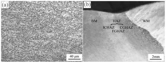
Figure 1.
(a) The microstructure of the X80 welded pipe base material and (b) the macrostructure of the zone near the welded joints.
2.2. Thermal Simulation Tests
Welding thermal simulation tests at different peak temperatures were carried out on a Gleeble-3800 thermal simulation tester (DSI, New York, NY, USA) to obtain materials in different sub-HAZs. Since the peak temperature in the HAZ decreased with increasing distance from the weld fusion zone, the peak temperatures at different locations from the weld fusion zone of the X80 welded pipe were calculated using the following equation [36]:
where T is the peak temperature, T0 is the preheating temperature, q/v is the welding heat input, t is the heating time, λ is the thermal conductivity, r is the radial distance from the heat source, and a is the thermal diffusivity.
It is calculated that thermal simulation specimens with peak temperatures of 1320 °C, 1020 °C, and 880 °C can be used to represent the CGHAZ, the FGHAZ, and the ICHAZ, respectively.
2.3. Tensile Property Tests
To better characterize the mechanical properties of the three typical subregions of the HAZ under hydrogen-charged conditions, slow strain rate tensile tests were conducted on the CGHAZ, FGHAZ, and ICHAZ samples under both hydrogen-charged and air conditions, and the stress–strain curves of the material were recorded. The slow strain rate tensile test was carried out according to the test method and sample size specified in the GBT228.1-2010 [37]. The test materials used were the materials from each sub-HAZ after the thermal simulation experiment, and the sample size is shown in Figure 2. Under the condition of keeping other test conditions consistent, the differences in the mechanical properties of each subregion after being hydrogen-charged were tested using different stretching rates, with stretching rates of 1 × 10⁻⁴ s−1, 1 × 10⁻³ s−1, and 1 × 10⁻² s−1. The electrolytic hydrogen-charged time was selected as 2 h. Electrolytic hydrogen charging was conducted using a CS2350M electrochemical workstation (CorrTest, Wuhan, China). The specimen is used as the cathode, and the platinum sheet is used as the anode. A 0.5 mol/L was used as the electrolyte solution, and 3.84 mmol/L Na2S was used as the toxic agent. The electrolytic hydrogen charging current is 20 mA/cm2. After hydrogen charging for 2 h, hydrogen content tests were conducted in the samples of three subregions using the ONH5500 test machine (NCS, Suzhou, China). The results indicated that the hydrogen content of all the hydrogen-charged samples in the three subregions was within the range of 6.4 ± 0.67 ppm. The tensile test without the hydrogen-charged condition was selected, with a strain rate of 1 × 10⁻⁴ s−1. The average value of the three samples was tested under the same experimental conditions. Each tensile test was carried out until the specimen broke. Data during the test were collected, and a stress–strain diagram was plotted.
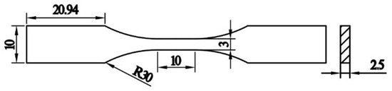
Figure 2.
Schematic of the specimen’s geometry for slow strain rate tensile tests.
2.4. Microstructure Analysis Test
The metallographic structure of each subregion in the real and thermally simulated HAZs of the X80 welded pipe was observed by using the Axiover 200MAT (ZEISS, Jena, Germany) optical microscope (OM), respectively, and the difference in metallographic structure between the thermally simulated specimen and the real HAZ was compared. The microstructure of the thermal simulation specimens was observed under secondary electron scanning at 10 kV using a S-3400N (Hitachi, Tokyo, Japan) scanning electron microscope (SEM). Both the specimens observed using the OM and SEM were polished and then corroded with 5% nitric acid alcohol. The grain size, grain orientation, and microstrain of each subregion in the real and thermally simulated HAZs were analyzed and compared using electron back-scattered diffraction (EBSD). The EBSD tests were carried out with each specimen placed on a plane parallel to the rolling direction (RD) and the cross-section direction (TD) of the X80 base material, and the test was conducted at an operating voltage of 20 kV with a step size of 0.2 μm. The SEM was also used to observe the fractography of the tensile sample to analyze the influencing factors of the difference in the degree of hydrogen damage in each subregion.
3. Results
3.1. Microstructure of the HAZ in the X80 Welded Pipe
The microstructure within each sub-HAZ in the X80 welded pipe is shown in Figure 3a–c. It can be seen that the CGHAZ is dominated by granular bainite (GB) (Figure 3a). Due to the high peak temperature, the grains are fully austenitizing during heating, and the grain size grows continuously, resulting in a coarse grain at room temperature. And the primary austenite grain boundary is clearly visible in the CGHAZ. The microstructure of the FGHAZ is mainly composed of polygonal ferrite (PF) and a small amount of acicular ferrite (AF) (Figure 3c). The PF is equiaxed, and the AF has a finer grain structure. Compared with the grains in the CGHAZ, the grain sizes of AF and PF are significantly reduced, and the primary austenite grain boundaries basically disappear. The ICHAZ structure undergoes partial phase transition recrystallisation as the austenitizing temperature is not reached. It is mainly composed of finer AF that has not undergone phase transformation, and a small amount of PF is produced by partial phase transformation recrystallization (Figure 3e). A comparison of the microstructures of the subregions in the simulated HAZ with those in the real HAZ shows that the microstructures of the two HAZs are similar. The thermally simulated CGHAZ consists of GB within the primary austenite grain boundaries (Figure 3b). The thermally simulated FGHAZ is composed of PF and a small amount of AF (Figure 3d). The thermally simulated ICHAZ is composed of even finer acicular and PF (Figure 3f). This result justifies the thermal simulation process in these three subregions of the HAZ.
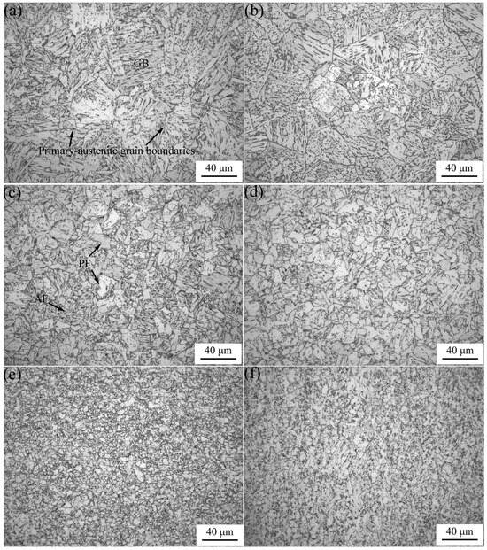
Figure 3.
X80 welded pipe HAZ of each subregion of the metallographic structure: the real HAZ (a) CGHAZ, (c) FGHAZ, and (e) ICHAZ; thermal simulation of the HAZ, (b) CGHAZ, (d) FGHAZ, and (f) ICHAZ.
The microstructures of each subregion in the real weld HAZ and thermal-simulated HAZ were characterized via EBSD, and the results are shown in Figure 4. It can be seen that the grain orientation of each subregion in the HAZ of the thermal simulation is basically the same as that of the real HAZ, which means that the properties of the sub-HAZs measured via the thermal simulation of the HAZ can reflect the real HAZ properties and microstructure changes. The grain orientation results show that the orientation of the bainite grains within the same primary austenite grain boundaries in the CGHAZ is similar, and the grains in the CGHAZ tend to be in the (111) and (001) orientations (Figure 4a,d). However, the difference in orientation between neighboring ferrite grains within the FGHAZ is large, and the grains’ orientation shows anisotropy (Figure 4b,e). The orientation change between most of the neighboring grains within the ICHAZ is large, while some grains within the ICHAZ appear to be oriented in the same rolling band orientation, indicating that these grains are not affected by the heating process and still retain a rolling state structure that is consistent with that of the base material (Figure 4c,f).
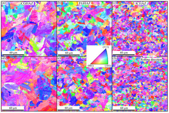
Figure 4.
EBSD analysis results of each subregion of the HAZ of the X80 welded pipe: (a) the CGHAZ, (b) FGHAZ, and (c) ICHAZ of the real HAZ and the (d) CGHAZ, (e) FGHAZ, and (f) ICHAZ of the HAZ of the thermal simulation.
Figure 5 shows the structure morphology of each sub-HAZ of the X80 welded pipe under SEM observation. The black matrix in the microstructure of the CGHAZ is the GB matrix, and the bright white is the GB grain boundary and the M/A structure (Figure 5a). Some of the primary austenite grain boundaries are clearly visible, and there are GBs with different orientations and morphologies distributed within the primary austenite grain boundaries. The bright white massive GBs are distributed inside and at the boundaries, along with coarse, massive, and striated M/A. The M/A is also found on trident grain boundaries, which consist of primary austenite grain boundaries. The AF in the FGHAZ is black, and the grain boundaries and M/A are bright white, and the local AF is distributed as a bunch (Figure 5b). The M/A in the FGHAZ is distributed between the AF laths and PF grain boundaries, with a small amount distributed inside the grains, and the massive M/A is significantly reduced. The size of AF grains in the ICHAZ is unevenly distributed, and the M/A at the grain boundaries and inside the grains is more finely distributed in the form of dots and particles (Figure 5c).
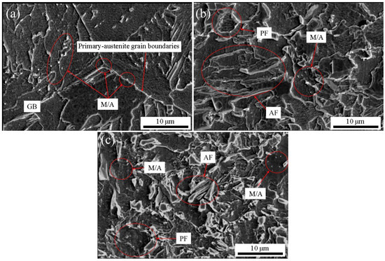
Figure 5.
SEM structure of X80 welded pipe thermal simulation in the HAZ in each subregion: (a) CGHAZ; (b) FGHAZ; (c) ICHAZ.
3.2. Tensile Properties of Each Sub-HAZ
Figure 6 shows the stress–strain curve of each sub-HAZ of the X80 welded pipe under different strain rates. Table 1 shows the tensile strength and total elongation of specimens in each subregion under different strain rates. The total elongation is the total strain at the time of specimen fracture during the tensile test. By comparing the specimens without hydrogen charging in each subregion, it can be seen that the CGHAZ has the highest tensile strength and the lowest total elongation in the welded HAZ, which are 663 MPa and 26.8%, respectively. The FGHAZ has the median tensile strength and lowest total elongation of 658 MPa and 28.5%, respectively. The ICHAZ has the lowest tensile strength of 653 MPa and the highest total elongation of 30.8%. In the elastic deformation stage of the material, the stress–strain curves of the specimens in each subregion under different strain rates before and after hydrogen charging were basically identical, indicating that there was basically no effect of hydrogen on the mechanical behavior of each subregion in the elastic stage under different loading rates. Moreover, the tensile strength of each subregion after hydrogen charging barely changed, in which the maximum difference in the tensile strength of the CGHAZ was 2.3% compared with that of the non-hydrogen charging sample; the maximum difference in tensile strength of the FGHAZ was 3.1%, and the maximum difference in tensile strength of the ICHAZ was 1.8%. However, the total elongation of the specimens with different strain rates decreased to a greater extent after hydrogen charging.
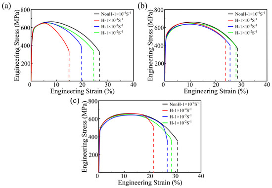
Figure 6.
Stress–strain curves in various subregions of the HAZ of the X80 welded pipe at different strain rates: (a) CGHAZ; (b) FGHAZ; (c) ICHAZ.
As can be seen from Table 2, the total elongation of each subregion shows a decreasing trend with a decreasing strain rate. At a strain rate of 1 × 10⁻⁴ s−1, the total elongation of specimens in each subregion affected by hydrogen is the lowest. Among them, the total elongation of the specimens in the CGHAZ decreased most seriously, and its total elongation decreased to 14.8%. Meanwhile, the total elongation in the FGHAZ decreased to 23.9%, and the total elongation in the ICHAZ decreased to 21.5%. The total elongation of the specimens affected by hydrogen in each subregion increased at a high strain rate of 1 × 10⁻² s−1, but it was still lower than that of the non-hydrogen charging specimens. Compared with the elongation of the non-hydrogen charging specimens, the elongation of the CGHAZ decreased to 24.5%, while the elongation of the FGHAZ decreased by only 0.1%, and the elongation of the ICHAZ decreased to 27.9%. It shows that at higher strain rates, the effect of hydrogen on the FGHAZ is small, while the elongation of the CGHAZ and the ICHAZ still has a greater degree of influence.
Table 2.
Tensile strength and total elongation of the X80 welded pipe in the HAZ under different strain rate conditions.
The total elongation of a material represents the plasticity of this material. The quantitative calculation of the degree of plastic damage to a material by hydrogen is generally derived from Equation (2) for hydrogen embrittlement sensitivity [22]:
where HE is the hydrogen embrittlement sensitivity index, I0 is the total elongation of the specimen under air condition, and I1 is the total elongation of the specimen under the electrolytic hydrogen charging condition.
Figure 7 shows the histogram of the hydrogen embrittlement sensitivity index under different strain rate conditions in each subregion. It can be seen that all three subregions have the highest hydrogen embrittlement sensitivity at a strain rate of 1 × 10⁻⁴ s−1. The highest value of 44.8% is found in the CGHAZ, and the lowest value of 16.1% is found in the ICHAZ. With the increase in strain rate, the hydrogen embrittlement sensitivity index of the CGHAZ decreased to 8.5%; the ICHAZ still had 9.4%, and the hydrogen embrittlement sensitivity index of the FGHAZ decreased to 0.3% when the strain rate became 1 × 10⁻² s−1. The results show that the strain rate has a great influence on the degree of plastic damage in the HAZ of the X80 welded pipe, especially in the CGHAZ, where the hydrogen embrittlement sensitivity index of the material is reduced by 36.3% when the strain rate is reduced from 1 × 10⁻² s−1 to 1 × 10⁻⁴ s−1. It can also be seen that the hydrogen embrittlement sensitivity index is the largest in the CGHAZ, followed by the ICHAZ, and the smallest in the FGHAZ at the slower strain rate. However, the hydrogen embrittlement sensitivity index of the ICHAZ becomes the largest when the strain rate is elevated to 1 × 10⁻² s−1, and therefore attention needs to be paid to the hydrogen damage behavior of the ICHAZ.
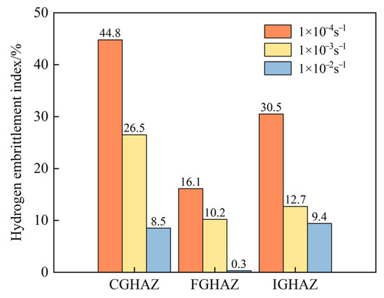
Figure 7.
Hydrogen embrittlement index in each sub-HAZ of the X80 welded pipe at different strain rates.
3.3. Tensile Fractography in Each Sub-HAZ
Figure 8 shows the macroscopic and microscopic fractography of the tensile specimens in the three sub-HAZs under the condition of no hydrogen charging. Figure 8a–c represent the macroscopic fractography in the CGHAZ, FGHAZ, and ICHAZ before hydrogen charging, respectively. It can be seen that the tensile fracture of the three subregions under the no hydrogen charging condition showed obvious necking and large plastic deformation around the fracture. The whole fracture is radial, which is a typical characteristic of ductile fractures. Smooth areas were found at the edges of the fracture in all three subregions, which were formed due to the unstable crack extension caused by the shear stress generated at the edge of the necking zone during unidirectional stretching. Figure 8d–f show the enlarged views corresponding to the red dashed line at the center of the macroscopic fracture in the three subregions. In the figure, it can be seen that the fractography at the center of the three sub-HAZs’ fracture is honeycomb-like. This is a kind of dimple formed by the growth and aggregation of microscopic pores generated during plastic deformation. The results show that the samples ductile fracture when subjected to slow strain rate stretching under non-hydrogen-charged conditions.
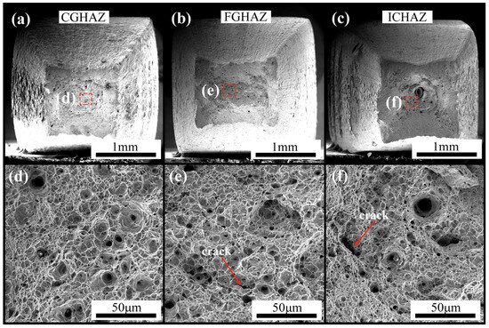
Figure 8.
Tensile fractography of various sub-HAZs of the X80 welded pipe without hydrogen charging: macroscopic morphology of the (a) CGHAZ, (b) FGHAZ, and (c) ICHAZ; local magnification of the (d) CGHAZ, (e) FGHAZ, and (f) ICHAZ.
Figure 9 shows the tensile fractography of the three subregions of the weld heat-affected zone at a strain rate of 1 × 10⁻⁴ s−1 under hydrogen-charged conditions. Figure 9a–c show the macroscopic fractography of hydrogen-charged specimens in the CGHAZ, FGHAZ, and ICHAZ, respectively. Compared with the fracture of the specimen without hydrogen charging, the macroscopic necking degree of the fracture of the specimen affected by hydrogen is reduced, and more obvious brittle fracture characteristics appear at the edge of the fracture. Figure 9d–f are local enlargements of the dashed area at the center of the tensile fracture after hydrogen charging in the CGHAZ, FGHAZ, and ICHAZ, respectively. It can be seen that the overall shape of the center position is a dimple, which is relatively shallow compared to the shape of the fracture without hydrogen charging. Among them, more microcracks appeared in the specimen in the CGHAZ, indicating that the CGHAZ was most affected by hydrogen among the three subregions. Figure 9g–i show the local magnification of the dashed area at the edge position of the tensile fracture after hydrogen charging in the CGHAZ, FGHAZ, and ICHAZ, respectively. It can be seen that in the local magnification of the fracture edge position in the CGHAZ, there is a large area of cleavage planes, and the river-like pattern is radial, which extends in all directions from the longer crack source in the central position, which is a typical characteristic of brittle fractures (Figure 9g). Figure 9h is a local magnification of the location of the fracture edge of the FGHAZ. The figure appears in the quasi-cleavage plane, and in a small amount of the slip separation process of the smooth plane, the area around the dimple is obviously shallow, the dimple’s morphology from the isometric dimple to the formation of shear dimple shear stresses is accompanied by a small number of dissolution planes. This is a kind of fracture mode between a brittle fracture and a ductile fracture, and the cleavage cracks expand into cleavage planes at different locations, and they finally fracture in a plastic manner. Figure 9i shows a magnified view of the fracture edge position in the ICHAZ. A large number of cleavage planes as well as river-like patterns appear in the figure, showing certain brittle fracture characteristics, and are accompanied by a small number of shallow shear dimples. The brittleness characteristics are more pronounced at the edge position of the ICHAZ compared to the FGHAZ.
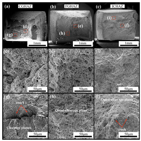
Figure 9.
Tensile fractography of X80 welded pipe HAZ subregions after hydrogen charging: macroscopic morphology of the (a) CGHAZ, (b) FGHAZ, and (c) ICHAZ; local magnification of fracture center of the (d) CGHAZ, (e) FGHAZ, and (f) ICHAZ; local magnification of the fracture edge of the (g) CGHAZ, (h) FGHAZ, and (i) ICHAZ.
4. Discussion
Comparing the tensile properties of the three subregions of the HAZ of the X80 welded pipe in the non-hydrogen-charged state, it is clear that the plasticity of the CGHAZ is the worst, at only 26.8% (Figure 6 and Table 1). In order to explain this phenomenon, the microstructure of each sub-HAZ in the non-hydrogen-charged state was analyzed via EBSD in the undeformed state and at 2.5% deformation at a strain rate of 1 × 10⁻⁴ s−1. As can be seen from the distribution of grain boundaries in the pristine state in the CGHAZ, the primary austenite grain boundaries are all blue with high-angle boundaries, whereas the grain boundaries between the bainite laths are mostly red with low-angle boundaries (Figure 10a). Low-angle boundaries are mainly formed by some sub-grain boundaries due to small orientation differences and the tilt and torsion between grains. Therefore, the microstrain is more concentrated where small-angle aggregation occurs, and the dislocation density here is also higher [24]. The high-strain regions in the CGHAZ are mainly concentrated at the bainite boundaries. This is because the bainite transformation is an intermediate temperature transformation, a transformation mechanism that usually does not involve diffusion processes of iron atoms but only carbon atoms [38]. High strain energy is induced, which results in a high and concentrated dislocation density between and within bainite slats in the CGHAZ. During the stretching process, a further increase in low-angle grain boundaries and microstrains between the bainite laths in the CGHAZ occurs due to plastic deformation (Figure 5, Figure 10d, Figure 11 and Figure 12d). The crack is generated, and the plasticity of the coarse crystal zone decreases in the CGHAZ. At the same time, the M/A distributed at the primary austenite grain boundaries and between the GB laths act as hard phases [23], where they exacerbate the strain concentration (Figure 5 and Figure 12a). Therefore, the presence of M/A promotes crack initiation during deformation and further exacerbates the embrittlement phenomenon in the CGHAZ, resulting in the CGHAZ becoming the zone with the lowest plasticity in the HAZ of the X80 welded pipe.
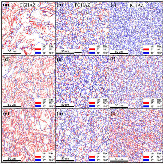
Figure 10.
The grain boundary distribution in the HAZ of the X80 welded pipe: CGHAZ: (a) undeformed, (d) deformed by 2.5% without hydrogen charging, and (g) deformed by 2.5% after hydrogen charging; FGHAZ: (b) undeformed, (e) deformed by 2.5% without hydrogen charging, and (h) deformed by 2.5% after hydrogen charging; and the ICHAZ: (c) undeformed, (f) deformed by 2.5% without hydrogen charging, and (i) deformed by 2.5% after hydrogen charging.
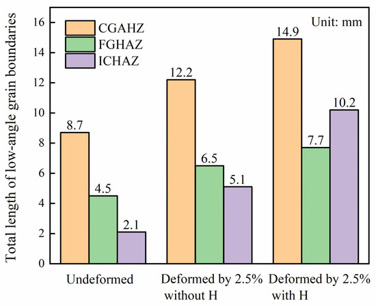
Figure 11.
The total length of low-angle grain boundaries in various sub-HAZs of the X80 welded pipe.
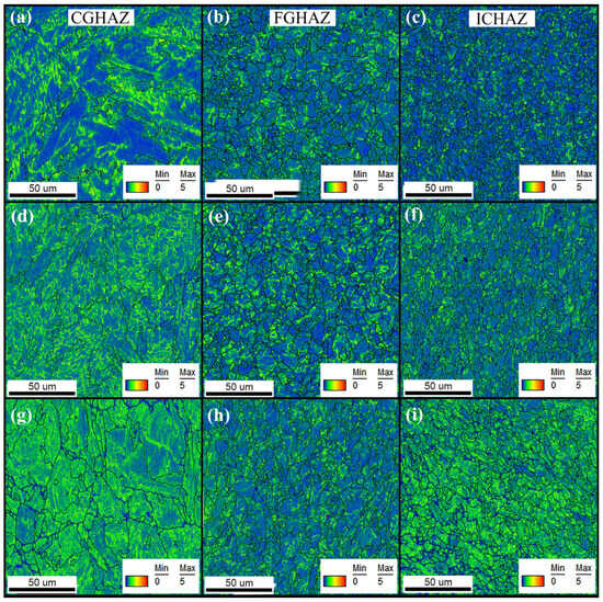
Figure 12.
The microstrain distribution in the HAZ of the X80 welded pipe: CGHAZ: (a) undeformed, (d) deformed by 2.5% without hydrogen charging, and (g) deformed by 2.5% after hydrogen charging; FGHAZ: (b) undeformed, (e) deformed by 2.5% without hydrogen charging, and (h) deformed by 2.5% after hydrogen charging; and the ICHAZ: (c) undeformed, (f) deformed by 2.5% without hydrogen charging, and (i) deformed by 2.5% after hydrogen charging.
In the undeformed state, there is a large orientation difference between the different ferrite grains in the FGHAZ and the ICHAZ (Figure 3), so the grain boundaries of the different ferrite grains form high-angle boundaries (Figure 10b,c). The high-strain region of the fine crystal region and the critical region is also mainly distributed in the FGHAZ, and ICHAZs are also mainly distributed in the low-angle boundaries. Therefore, the low-angle boundaries in the ICHAZ are the least, and the induced microstrains are much smaller than the other two subregions (Figure 12a–c).
After deformation, the low-angle grain boundaries in the critical crystal region increase significantly (Figure 11), but the proportion of high-strain regions generated is still less than that in the fine crystal region (Figure 12e,f). At the same time, compared with the microstructure in the ICHAZ, the M/A generated by complete phase change recrystallization in the FGHAZ is much larger than that in the ICHAZ. The distribution of M/A in the ICHAZ is relatively uniform, and less prone to stress concentration (Figure 5 and Figure 12b), which reduces the probability of crack initiation. Therefore, compared with the ICHAZ, the FGHAZ is more prone to crack initiation. In addition, it can also be seen from the tensile fracture of the non-hydrogen-charged specimen that the dimples in the ICHAZ are larger and deeper (Figure 8), which is also a manifestation of the high plastic deformation capacity. Therefore, in the non-hydrogen-charged state, the ICHAZ has the best plasticity, with a high total elongation of 30.8%.
At lower strain rates (<1 × 10⁻³ s−1), the hydrogen embrittlement sensitivity of the hydrogen-charged CGHAZ is the highest. Especially, when the strain rate is at 1 × 10⁻⁴s−1, the total elongation decrease in the CGHAZ is as high as 44.8%. This result indicates that the CGHAZ is most severely plastically damaged by hydrogen at low strain rates in the HAZ, which is consistent with the findings of Zhang et al. [28]. The hydrogen embrittlement behavior of the material is closely related to its microstructures [39,40]; therefore, the microstructures of the CGHAZ after deformation under the influence of hydrogen were further investigated using EBSD (Figure 10g and Figure 12g). Compared with the CGHAZ in the non-hydrogen-charged state, the low-angle boundaries of the CGHAZ after hydrogen filling extend to the inside of the bainite slats except along the GB (Figure 10d,g). The microstrain inside the GB also increases greatly (Figure 12d,g). According to the HELP theory, hydrogen is able to enhance dislocation mobility by decreasing the critical stress of the dislocations and promote the proliferation and movement of the dislocations during the deformation process [41,42]. Due to the presence of primary dislocations at GB, a strong trapping energy is generated at the grain boundaries, which binds the migration and diffusion of hydrogen atoms [43]. At the same time, the binding effect of dislocations on hydrogen causes hydrogen to move along with the dislocations [44]. The aggregated hydrogen atoms push the dislocations closer to the grain boundaries, resulting in the proliferation of dislocations at the grain boundaries. Thus, the introduction of hydrogen exacerbates the increase in microstrain near the grain boundaries of the GB in the CGHAZ. The M/A structure distributed between the bainite laths acts as a heterogeneous phase and will provide a new phase interface. Hydrogen atoms within the GB will create dislocation loops around the M/A structure during dislocation slip, leading to the occurrence of high-density dislocations between the GB in the CGHAZ after hydrogen charging [16]. Areas with a high dislocation density cause dislocation entanglement, which hinders dislocation slip and leads to the formation of cleavage fractures (Figure 9g), leading to a reduction in the plasticity of the CGHAZ. In addition, hydrogen atoms enter into the material, regardless of the presence of primary dislocations or strain-induced dislocations, which affects the aggregation of hydrogen atoms. Hydrogen atoms aggregated at defects such as dislocations and grain boundaries in the CGHAZ will be compounded into hydrogen molecules, resulting in a local hydrogen concentration difference, and the hydrogen atoms will diffuse to the surrounding low-concentration regions and reaggregate. The continuous compounding of hydrogen atoms into hydrogen molecules leads to an increase in the internal pressure at the defects [45,46]. When the stress caused by the hydrogen pressure exceeds the critical stress for crack formation in the material, it leads to cracking and further reduces the plasticity of the material. As a result, a sharp reduction in plasticity occurs in the CGHAZ after hydrogen charging.
After hydrogen charging, all subregions of the specimens showed a large area in the high-strain zone after deformation, indicating that the synergistic effect of hydrogen atoms and a lower strain rate can promote the multiplication of dislocations and increase the capture efficiency of hydrogen atoms in the internal microstructure of the material. Among them, the microstrain region in the FGHAZ is less variable, and the high-strain region is more uniformly distributed. As a result, the degree of dislocation pile-up in the FGHAZ is lower, and the efficiency of capturing hydrogen atoms is also lower. The degree of plastic damage caused by hydrogen atoms depends on the rate of hydrogen segregation to dislocations and the slip rate of dislocations. The strain rate is directly proportional to the rate of dislocation movement, i.e., the rate of dislocation movement increases as the strain rate increases [47]. When a slower strain rate is used, hydrogen atoms and dislocations fully interact with each other, and as the dislocations slip, the dislocations carry a high concentration of hydrogen atoms in the dislocation slipping process as obstacles to the aggregation. On the other hand, the dislocation pile-up is generally released through forms such as disintegration or climb migration and takes more sufficient time to complete compared to dislocation slips [48]. Therefore, at lower strain rates, the dislocations entangled in the matrix have enough time to be released. This results in a more severe degree of dislocation plugging and a more efficient diffusion of dislocation-carrying hydrogen at low strain rates. Macroscopically, it is shown that at lower strain rates, materials in different subregions of the HAZ exhibit higher hydrogen embrittlement sensitivity indices than at higher strain rates (Figure 7). At low rates of plastic deformation, the dislocation hydrogen-carrying efficiency is significantly higher in the CGHAZ composed of GB with higher dislocation density than in the FGHAZ and ICHAZs. At the same time, the primary austenite grain boundaries can also serve as channels for hydrogen diffusion, accelerating the movement of hydrogen atoms [49]. The coarse M/A is also prone to local stress concentration, and multiple factors together lead to a strong hydrogen embrittlement sensitivity in the CGHAZ. The density of primary dislocations of the AF and PF in the FGHAZ and ICHAZs is lower than that in the CGHAZ, and the capture efficiency for hydrogen is also lower than that of the CGHAZ. With the occurrence of plastic deformation, the local dislocation density in the ICHAZ is much higher than that in the FGHAZ (Figure 10h,i and Figure 12). During the heating process, the ICHAZ contains extremely fine AF grains that have not undergone a phase transformation, and the smaller grain size implies a greater number of grain boundaries (Figure 3). In contrast, complete phase transformation and recrystallization occur in the FGHAZ, resulting in a significant reduction in fine AF grains. During the deformation process, dislocations accumulate at the AF grain boundaries in the ICHAZ, leading to a higher local dislocation density than that in the FGHAZ (Figure 12h,i). As a result, the ICHAZ exhibits a higher hydrogen embrittlement sensitivity than the FGHAZ. Because of this, the fracture of specimens with locally higher dislocation densities in the ICHAZ also showed a larger area of cleavage planes and more microcracks than in the FGHAZ, resulting in a fracture with more pronounced brittle fracture characteristics (Figure 9i).
When the strain rate is increased to 1 × 10⁻² s−1, the ICHAZ shows a higher hydrogen embrittlement sensitivity index than the CGHAZ. At high strain rates, the rate at which hydrogen atoms enter the matrix and cluster around dislocations cannot keep up with the dislocation slip speed, resulting in a lower concentration of hydrogen atoms carried by dislocations. Therefore, compared with low strain rates, the damage effect of hydrogen is significantly reduced at high strain rates (Figure 7). However, due to the largest number of high-angle boundaries in the ICHAZ caused by fine grains and the large orientation difference between grains on both sides of the high-angle boundaries, the ability to capture hydrogen atoms in the ICHAZ is enhanced. (Figure 10c). Meanwhile, the ability of the CGHAZ and FGHAZ to capture hydrogen significantly decreases at high strain rates. Additionally, during deformation, the high density of dislocations generated by AF grains in the ICHAZ also increases the local concentration of hydrogen atoms, and the resulting high-strain regions thereby lead to a large stress concentration gradient in the ICHAZ, which is prone to microcrack initiation and reduces the material’s plasticity [50]. Therefore, at high strain rates, the ICHAZ suffers the highest degree of damage due to hydrogen.
5. Conclusions
In this paper, each sub-HAZ of the X80 welded pipe is taken as the research object, the hydrogen damage behavior of each sub-HAZ under different strain rates is studied. The reasons for the differences in hydrogen embrittlement sensitivity in each sub-HAZ are analyzed. The conclusions are as follows:
- When deformed at a low strain rate of less than 1 × 10⁻³ s−1, the CGHAZ of the X80 welded pipes shows the highest hydrogen embrittlement sensitivity, followed by the ICHAZ, and the FGHAZ has the lowest sensitivity. When deformed at a strain rate of 1 × 10⁻⁴ s−1, the hydrogen embrittlement sensitivity of the ICHAZ in the HAZ becomes the highest, followed by the CGHAZ, while the FGHAZ is almost unaffected. Therefore, when designing and using X80 welded pipes for hydrogen transportation, while paying attention to the hydrogen damage behavior in the CGHAZ, the hydrogen damage behavior in the ICHAZ should not be ignored.
- The granular bainite structure in the CGHAZ has a higher hydrogen embrittlement sensitivity. After being affected by hydrogen, the granular bainite grains have the most low-angle boundaries and high-strain regions during deformation. Next is the acicular ferrite in the ICHAZ. The polygonal ferrite in the FGHAZ is least affected by hydrogen.
- At high strain rates, the efficiency of hydrogen loading on dislocations decreases, and hydrogen atoms are more likely to be captured by grain boundaries, leading to the formation of high-strain regions. The ICHAZ, composed of fine grains, has the most high-angle boundaries and thus has the greatest ability to capture hydrogen. This is the main reason for the high hydrogen embrittlement sensitivity in the ICHAZ at high strain rates.
Author Contributions
Conceptualization, W.L.; Methodology, W.L., R.-X.B. and B.-H.C.; Validation, B.-C.G., R.-X.B. and B.-H.C.; Formal analysis, B.-C.G. and J.-T.S.; Investigation, L.T. and B.-H.C.; Resources, J.-T.S. and R.-X.B.; Data curation, W.L, B.-C.G. and J.-T.S.; Writing—original draft, L.T., W.L. and K.X.; Writing—review & editing, K.X., G.-Y.Q. and F.-R.X.; Visualization, L.T. and B.-H.C.; Supervision, K.X. and F.-R.X.; Project administration, F.-R.X.; Funding acquisition, K.X. and G.-Y.Q. All authors have read and agreed to the published version of the manuscript.
Funding
This work was supported by the S&T Program of Hebei (No. 22314601D); the Natural Science Foundation of Hebei Province (Grant No. E2022203174).
Data Availability Statement
The datasets generated during and/or analyzed during the current study are available from the first author upon reasonable request.
Conflicts of Interest
Author Ji-Tong Sha was employed by the company HCIG New-Energy Co., Ltd. The remaining authors declare that the research was conducted in the absence of any commercial or financial relationships that could be construed as a potential conflict of interest.
References
- Smith, C.; Hill, A.K.; Torrente-Murciano, L. Current and Future Role of Haber–Bosch Ammonia in a Carbon-Free Energy Landscape. Energy Environ. Sci. 2020, 13, 331–344. [Google Scholar] [CrossRef]
- Koohi-Fayegh, S.; Rosen, M.A. A Review of Energy Storage Types, Applications and Recent Developments. J. Energy Storage. 2020, 27, 101047. [Google Scholar] [CrossRef]
- Herib, B.; André, F. A review at the role of storage in energy systems with a focus on Power to Gas and long-term storage. Renew. Sustain. Energy Rev. 2018, 81, 1049–1086. [Google Scholar] [CrossRef]
- Dawood, F.; Anda, M.; Shafiullah, G.M. Hydrogen Production for Energy: An Overview. Int. J. Hydrogen Energy 2020, 45, 3847–3869. [Google Scholar] [CrossRef]
- Jaworski, J.; Kułaga, P.; Blacharski, T. Study of the Effect of Addition of Hydrogen to Natural Gas on Diaphragm Gas Meters. Energies 2020, 13, 3006. [Google Scholar] [CrossRef]
- Omar, B.; Zahreddine, H.; Milos, B.D.; Elaoud, S. The synergistic effects of hydrogen embrittlement and transient gas flow conditions on integrity assessment of a precracked steel pipeline. Int. J. Hydrogen Energy 2020, 45, 18010–18020. [Google Scholar]
- Nazir, H.; Muthuswamy, N.; Louis, C.; Jose, S.; Prakash, J.; Buan, M.E.; Flox, C.; Chavan, S.; Shi, X.; Kauranen, P.; et al. Is the H2 economy realizable in the foreseeable future? Part II: H2 storage, transportation, and distribution. Int. J. Hydrogen Energy 2020, 45, 20693–20708. [Google Scholar] [CrossRef]
- Yu, Q.; Hao, Y.; Ali, K.; Hua, Q.; Sun, L. Techno-economic analysis of hydrogen pipeline network in China based on levelized cost of transportation. Energy Convers. Manag. 2024, 301, 118025. [Google Scholar] [CrossRef]
- Battersby, P.N.; Averill, A.F.; Ingram, J.M.; Holborn, P.G.; Nolan, P.F. Suppression of hydrogen–oxygen–nitrogen explosions by fine water mist: Part 2. Mitigation of vented deflagrations. Int. J. Hydrogen Energy 2012, 37, 19258–19267. [Google Scholar] [CrossRef]
- Meng, B.; Gu, C.H.; Lin, Z.; Zhou, C.; Li, X.; Zhao, Y.; Zheng, J.; Chen, X.; Han, Y. Hydrogen effects on X80 pipeline steel in high-pressure natural gas/hydrogen mixtures. Int. J. Hydrogen Energy 2017, 42, 7404–7412. [Google Scholar] [CrossRef]
- Chi, M.; Zeng, X.; Gao, Y.; Jiangg, H.; Xu, T.; Xiong, F. Experimental and numerical studies on ductile fracture behavior of X80 pipeline steel: Phase ratio and grain size. J. Mater. Res. Technol. 2025, 35, 7018–7036. [Google Scholar] [CrossRef]
- Wiskel, J.B.; Li, X.; Ivey, D.G.; Henein, H. Characterization of X80 and X100 Microalloyed Pipeline Steel Using Quantitative X-ray Diffraction. Metall. Mater. Trans. B 2018, 49, 1597–1611. [Google Scholar] [CrossRef]
- Ohaeri, E.G.; Qin, W.; Szpunar, J. A critical perspective on pipeline processing and failure risks in hydrogen service conditions. J. Alloys Compd. 2021, 857, 158240. [Google Scholar] [CrossRef]
- Yang, G.; Guo, Z.; Li, Z.; Liang, L.; Zhang, Y.; Guo, H.; Wang, C.; Xu, K.; Li, L. Effect of hydrogen on low-cycle fatigue properties and the mechanism of hysteresis energy method lifetime prediction of X80 pipeline steel. Corros. Sci. 2025, 243, 112599. [Google Scholar] [CrossRef]
- Wang, H.; Zhang, C.; Ma, H.; Tong, Z.; Huang, Y.; Jin, Y.; Su, C.; Zheng, W. Assessing the effects of loading rate on fracture toughness of AISI 1020 and API 5L X80 steels with hydrogen charging: Experimental and numeric simulation study. Eng. Fract. Mech. 2025, 314, 110771. [Google Scholar] [CrossRef]
- Olden, V.; Alvaro, A.; Akselsen, O.M. Hydrogen diffusion and hydrogen influenced critical stress intensity in an API X70 pipeline steel welded joint e experiments and FE simulations. Int. J. Hydrogen Energy 2012, 37, 11474–11486. [Google Scholar] [CrossRef]
- Zhao, W.; Zhang, T.; Zhao, Y.; Sun, J.; Wang, Y. Hydrogen Permeation and Embrittlement Susceptibility of X80 Welded Joint under High-Pressure Coal Gas Environment. Corros. Sci. 2016, 111, 84–97. [Google Scholar] [CrossRef]
- Kang, X. Hydrogen embrittlement of carbon steels and their welds. In Gaseous Hydrogen Embrittlement of Materials in Energy Technologies; Woodhead Publishing: Sawston, UK, 2012; pp. 526–561. [Google Scholar] [CrossRef]
- Duan, R.H.; Wang, Y.Q.; Luo, Z.A.; Wang, G.D.; Xie, G.M. Hydrogen Embrittlement Behavior in the Nugget Zone of Friction Stir Welded X100 Pipeline Steel. Int. J. Hydrogen Energy 2023, 48, 8296–8309. [Google Scholar] [CrossRef]
- Sun, Y.; Fujii, H.; Imai, H.; Kondoh, K. Suppression of Hydrogen-Induced Damage in Friction Stir Welded Low Carbon Steel Joints. Corros. Sci. 2015, 94, 88–98. [Google Scholar] [CrossRef]
- Li, Q.; Deng, C.; Wu, S.; Zhao, H.; Xu, X.; Liu, Y.; Gong, B. Coupled effect of microstructure heterogeneity and hydrogen on local embrittlement of CGHAZ and IC-CGHAZ in X65 pipeline steel. Mater. Sci. Eng. A 2024, 917, 147391. [Google Scholar] [CrossRef]
- Ngyen, T.T.; Beak, U.B.; Park, J.; Nahm, S.H.; Tak, N. Hydrogen environment assisted cracking in X70 welding heat-affected zone under a high-pressure hydrogen gas. Theor. Appl. Fract. Mech. 2020, 109, 102746. [Google Scholar] [CrossRef]
- Yan, Y.; Li, L.; Wang, H.; He, N.; Sun, Y.; Xu, L.; Li, L.; Li, H.; Wang, Z.; Zhang, C.; et al. Investigation of hydrogen embrittlement senitivity of X65 pipeline steel with different compositions employing thermal simulation. Int. J. Hydrogen Energy 2024, 84, 118–131. [Google Scholar] [CrossRef]
- Zhao, Z.P.; Qiao, G.Y.; Li, G.P.; Yang, W.W.; Liao, B.; Xiao, F.R. Fatigue properties of ferrite/bainite dual-phase X80 pipeline steel welded joints. Sci. Technol. Weld. Join. 2017, 22, 217–226. [Google Scholar] [CrossRef]
- Xu, K.; Qiao, G.Y.; Wang, J.S.; Zhang, S.Y.; Xiao, F.R. Research on the fatigue properties of sub-heat-affected zones in X80 pipe. Fatigue Fract. Eng. Mater. Struct. 2020, 43, 2915–2927. [Google Scholar] [CrossRef]
- Gao, Z.W.; Gong, B.M.; Wang, B.Y.; Wang, D.; Deng, C.; Yu, Y. Effect of fatigue damage on the hydrogen embrittlement sensitivity of X80 steel welded joints. Int. J. Hydrogen Energy 2021, 46, 38535–38550. [Google Scholar] [CrossRef]
- Gao, Z.; Wu, S.; Xiang, T.; Deng, C. Coupling effect of post-weld heat treatment and fatigue damage on the hydrogen embrittlement of X80 steel welded joints. J. Mater. Res. Technol. 2024, 31, 2646–2657. [Google Scholar] [CrossRef]
- Zhang, T.; Zhao, W.; Deng, Q.; Jiang, W.; Wang, Y.; Wang, Y.; Jiang, W. Effect of microstructure inhomogeneity on hydrogen embrittlement susceptibility of X80 welding HAZ under pressurized gaseous hydrogen. Int. J. Hydrogen Energy 2017, 42, 25102–25113. [Google Scholar] [CrossRef]
- Gou, J.; Nie, R.; Xing, X.; Cui, G.; Liu, J.; Deng, X.; Cheng, Y.F. Hydrogen-induced cracking of welded X80 steel studies by experimental testing and molecular dynamics modeling. Corros. Sci. 2023, 214, 111027. [Google Scholar] [CrossRef]
- Gou, J.; Xing, X.; Cui, G.; Li, Z.; Liu, J.; Deng, X.; Cheng, Y.F. Effect of hydrogen on impact fracture of X80 steel weld: Various heat inputs and coarse grain heat-affected zone. Mater. Sci. Eng. A 2023, 886, 145673. [Google Scholar] [CrossRef]
- Gou, J.; Xing, X.; Cui, G.; Li, Z.; Liu, J.; Deng, X. Hydrogen-Induced Cracking in CGHAZ of Welded X80 Steel under Tension Load. Metals 2023, 13, 1325. [Google Scholar] [CrossRef]
- Li, G.; Du, M. Electrochemical corrosion, hydrogen penetration and stress corrosion cracking behavior of X80 steel heat-affected zone in sulfate-reducing bacteria-containing seawater. Corros. Sci. 2025, 243, 112590. [Google Scholar]
- Świerczyńska, A.; Fydrych, D.; Landowski, M.; Rogalski, G.; Łabanowski, J. Hydrogen embrittlement of X2CrNiMoCuN25–6-3 super duplex stainless steel welded joints under cathodic protection. Constr. Build. Mater. 2020, 238, 117697. [Google Scholar] [CrossRef]
- Zhang, T.; Wang, Y.; Zhao, W.; Tang, X.; Du, T.; Yang, M. Hydrogen permeation parameters of X80 steel and welding HAZ under high pressure coal gas environment. Acta Metall. Sin. 2015, 51, 1101–1110. [Google Scholar]
- Masoumi, M.; Herculano, L.F.G.; de Abreu, H.F.G. Study of texture and microstructure evaluation of steel API 5L X70 under various thermomechanical cycles. Mater. Sci. Eng. A 2015, 639, 550–558. [Google Scholar]
- Kim, S.; Kang, D.; Kim, T.-W.; Lee, J.; Lee, C. Fatigue crack growth behavior of the simulated HAZ of 800MPa grade high-performance steel. Mater. Sci. Eng. A 2011, 528, 2331–2338. [Google Scholar] [CrossRef]
- GB/T 228.1-2010; Metallic materials—Tensile testing—Part 1: Method of test at room temperature. Standards Press of China: Beijing, China, 2010.
- Yu, S.F.; Qian, B.N.; Guo, X.M. Effect of accelerating cooling on microstructure and toughness of HAZ of X70 pipeline steel. Acta Metall. Sin. 2005, 41, 402–406. [Google Scholar]
- Li, L.; Guo, Z.; Ma, Y.; Tang, L.; Xu, K. Multi-scale hydrogen embrittlement prediction model of low alloy steel based on multi-dimensional defect reconstruction. Eng. Fract. Mech. 2025, 313, 110644. [Google Scholar] [CrossRef]
- Dwivedi, S.K.; Vishwakarma, M. Hydrogen embrittlement in different materials: A review. Int. J. Hydrogen Energy 2018, 43, 21603–21616. [Google Scholar] [CrossRef]
- Gong, P.; Nutter, J.; Rivera-Diaz-Del-Castillo, P.E.J.; Rainforth, W.M. Hydrogen embrittlement through the formation of low-energy dislocation nanostructures in nanoprecipitation-strengthened steels. Sci. Adv. 2020, 6, eabb6152. [Google Scholar] [CrossRef]
- Birnbaum, H.K.; Sofronis, P. Hydrogen-enhanced localized plasticity–A mechanism for hydrogen-related fracture. Mater. Sci. Eng. A 1994, 176, 191–202. [Google Scholar] [CrossRef]
- Chen, Y.-S.; Lu, H.; Liang, J.; Rosenthal, A.; Rosenthal, A.; Liu, H.; Sneddon, G.; McCarroll, I.; Zhao, Z.; Li, W.; et al. Observation of hydrogen trapping at dislocations, grain boundaries, and precipitates. Science 2020, 367, 171–175. [Google Scholar] [CrossRef]
- Li, L.; Liang, L.; Wang, Y.; Liu, J.; Sun, M.; Zhao, P.; Hu, J.; Xu, G.; Wang, G.; Xu, K. In situ study on the orientation and strain-rate correlation mechanism of hydrogen embrittlement behavior of ferrite under shear stress. J. Mater. Res. Technol. 2024, 33, 9674–9692. [Google Scholar]
- Venezuela, J.; Liu, Q.; Zhang, M.; Zhou, Q.; Atrens, A. A review of hydrogen embrittlement of martensitic advanced high-strength steels. Corros. Rev. 2016, 34, 153–186. [Google Scholar]
- Louthan, M.R., Jr. Strain localization and hydrogen embrittlement. Scr. Metall. 1983, 17, 451–454. [Google Scholar]
- Liu, J.H.; Wang, L.; Wang, X.S. Effect of strain rate on hydrogen embrittlement sensitivity of H2 charged SA508-III steel. Heat Treat. Met. 2018, 43, 227. [Google Scholar]
- Dong, D.Y.; Liu, Y.; Wang, L.; Su, L. Effect of strain rate on dynamic deformation behavior of DP780 steel. Acta Metall. Sin. 2013, 49, 159. [Google Scholar]
- Zhou, X.; Song, J. Effect of local stress on hydrogen segregation at grain boundaries in metals. Mater. Lett. 2017, 196, 123–127. [Google Scholar] [CrossRef]
- Naragani, D.; Sangid, M.D.; Shade, P.A.; Schuren, J.C.; Sharma, H.; Park, J.S.; Kenesei, P.; Bernier, J.V.; Turner, T.J.; Parr, I. Investigation of fatigue crack initiation from a non-metallic inclusion via high energy x-ray diffraction microscopy. Acta Mater. 2017, 137, 71–84. [Google Scholar] [CrossRef]
Disclaimer/Publisher’s Note: The statements, opinions and data contained in all publications are solely those of the individual author(s) and contributor(s) and not of MDPI and/or the editor(s). MDPI and/or the editor(s) disclaim responsibility for any injury to people or property resulting from any ideas, methods, instructions or products referred to in the content. |
© 2025 by the authors. Licensee MDPI, Basel, Switzerland. This article is an open access article distributed under the terms and conditions of the Creative Commons Attribution (CC BY) license (https://creativecommons.org/licenses/by/4.0/).