Abstract
Annealing and rolling play critical roles in improving the mechanical properties of arc spraying coatings. In this work, we successfully fabricated copper–steel bimetallic sheets (CSBSs) using an arc spray-rolling short process and achieved excellent internal bonding of the copper coating and improved deep-drawing of the CSBSs via annealing and rolling synergistic treatment. The results indicate that the microstructure of the copper coating became dense, and the porosity effectively reduced after annealing–rolling–annealing (ARA) treatment. Tight bonding was also observed between the copper coating and steel substrate. The copper coating had a porosity of less than 0.2%, an average grain size of 3.8 μm, and a micro-hardness of 55 HV0.05. After tensile testing, the As-sprayed coating generated brittle fractures and delamination. The A-R-A coating also displayed elongated dimples, with the majority oriented along the TD direction, and bonded well with the steel substrate. In addition, the As-sprayed coating fell off directly after deep drawing. In contrast, the A-R-A coating did not exhibit cracks and fall off. The fracture mechanism gradually changed from falling off and cracking, to toughness deformation due to the reduced porosity and tighter grain boundaries, and finally to cooperative deformation due to the metallurgical bonding of the sprayed particles and good interface bonding properties. These findings provide guidance and reference for the practical application of thermal spray additive manufacturing.
1. Introduction
Laminated metal composites (LMCs) are new materials that are created by combining two or more metals with different properties through physical or chemical methods. Due to their superior properties and economic advantages, they have gradually replaced some single-metal products [1]. Among these materials, copper–steel bimetallic sheets (CSBSs) play a significant role in the aerospace, construction, military, and electronic industries, among others, due to the strength of steel, the corrosion resistance of copper, and their high conductivity and thermal properties. They are crucial materials in bimetallic composites [2].
After years of development, the methods for preparing LMCs have become increasingly mature. Among these, thermal spraying technology, one of the deposition composite methods, is expected to become a new preparation process for double- or multi-layer LMCs due to its high deposition efficiency, low production cost, and flexible operation [3,4]. However, forming a strong and dense copper layer on steel using only arc spraying technology is difficult. This difficulty mainly arises from void formation in the coating during spraying, as well as oxide generation and stress concentration during re-solidification. Additionally, controlling the coating thickness uniformity is a challenge [5]. These factors significantly limit the coating’s processing performance. Several methods have been applied in arc spraying to optimize coating performance, including using inert gases like argon as carriers to reduce oxides, adjusting the spraying power and pressure to reduce porosity, and polishing the substrate before spraying [6,7]. However, using argon as a carrier is costly, and adjusting spray parameters or polishing substrates have a limited impact on improving the coating’s mechanical properties and adhesion.
Combining spraying and rolling is a viable composite preparation method, as rolling can thin, homogenize, and densify the coating [8]. However, untreated coatings do not have room-temperature rolled properties. During the rolling process, the coating always breaks or delaminates. This is because the sprayed coating often exhibits high residual stress and defects (such as voids and oxidation), which negatively impact its rolling performance [9]. Zhang et al. [10] found that the interface of ZW31/PMMC composite sheets that extruded without annealing exhibited numerous defects and poor interface bonding quality. Therefore, the sprayed coating must undergo an annealing treatment before rolling to optimize the interface and microstructure of the composite plate, ensuring it meets the requirements for rolling. Clearly, the process parameters of both rolling and annealing are critical factors in this composite preparation process. By adjusting the rolling reduction, number of rolling passes, and annealing insulation temperature and time, high-performance CSBSs can be produced. However, excessive reduction increases processing costs, while too many rolling passes can exacerbate work hardening [11,12,13]. Additionally, an improper insulation temperature and time may prevent the achievement of an optimal copper layer performance [14,15]. Moreover, after cold rolling, stress relief annealing is required for the CSBS. This process can reduce residual internal stresses in sheets [16,17]. However, there is limited research on the preparation of bimetallic composite sheets using a combination of arc spraying, rolling, and annealing processes.
In this study, we developed a novel method for preparing copper–steel bimetallic sheets (CSBSs) using a combination of arc spraying technology, rolling, and annealing processes. By leveraging spray, annealing, and cold rolling parameters derived from previous orthogonal experiments, CSBSs with excellent mechanical properties were successfully fabricated. The characterization and comparison of the microstructure and mechanical properties of the coatings in different states provide useful insights for advancing thermal spray rolling composite preparation technology in the field of metal composite materials.
2. Materials and Methods
2.1. Materials and CSBS Preparation
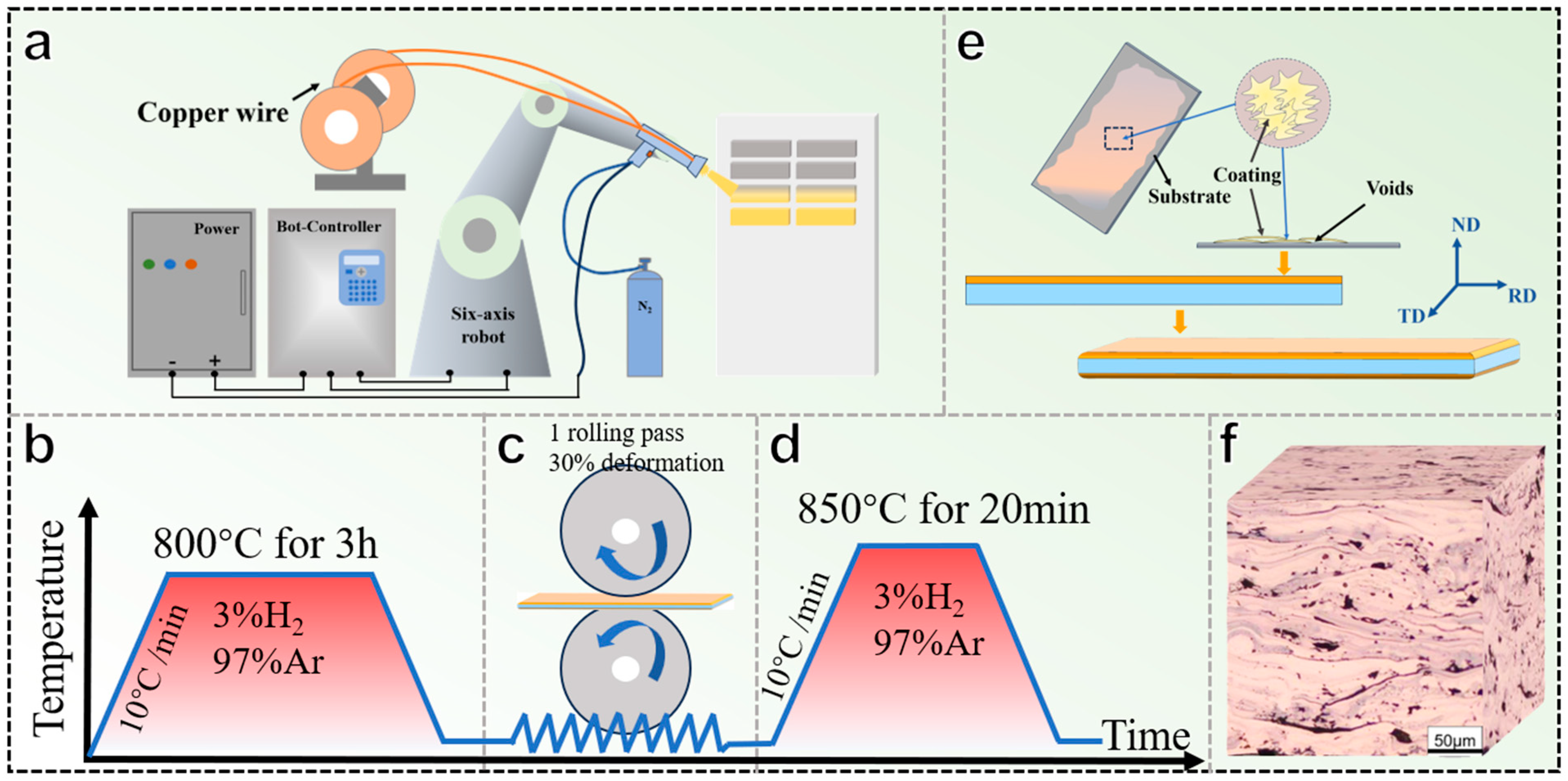
The substrate was commercial AISI 1015 (Maoteng Metal Material Co., Ltd., Dongguan, China) with a size of 150 mm × 45 mm × 4 mm. The sprayed wire material was commercial T1 pure copper wire (Jinkai Metal Material Co., Ltd., Laiyang, China) with a diameter of 2 mm. Before spraying, the surface of the steel was polished using a sanding machine (ATB1A-3100, Saiwider Robot Co., Ltd., Shanghai, China) with 80 grit sandpaper to remove the oxide layer and improve the surface roughness. The Cu coating was fabricated using an arc spraying system (DH-600A, Deyang Instrument Co., Ltd., Deyang, China). Figure 1 schematically presents the preparation process of the CSBS samples. During spraying, the spray gun was clamped onto a six-axis industrial robotic arm (AR1440, Yaskawa Robotics Co., Ltd., Kitakyushu, Japan) and sprayed along the S-shaped spraying trajectory (Figure 1a). The spraying process was protected in a N2 atmosphere. The lateral movement speed of the spray gun was 400 mm/s, and the specific spraying parameters are shown in Table 1. A coating layer of 250–300 μm thickness was sprayed onto both surfaces of the substrate, resulting in an overall thickness of 4.6 mm for the CSBSs. After CSBS preparation, post-processing was performed as shown in Figure 1b–d. The macroscopic and surface morphology diagrams of the prepared CSBS samples, as well as the metallographic phase diagram of the coating cross section, are shown in Figure 1e,f.

Figure 1.
Schematic diagram of CSBS preparation process: (a) arc spraying system, (b) first annealing process, (c) cold-rolling process, (d) second annealing process, (e) schematic diagram of molten particle deposition, and (f) morphology of coating.

Table 1.
Arc spraying parameters.
In the following description, As-sprayed, S-A, S-A-R, and S-A-R-A represent CSBS samples in the sprayed state, after the first annealing, after rolling, and after the second annealing, respectively.
2.2. Microstructure and Composition Characterization
The prepared CSBS sample was wire cut into small samples of 10 × 10 mm. We ground the cross section of the samples parallel to the rolling direction with sandpaper of 100, 240, 600, 1000, 1500, and 2000 mesh in sequence, and we then polished them with 2.5 and 0.5 μm alumina grinding paste. We observed the void and oxide layer distribution of the coating using an optical microscope (DMI5000M, Leica Microsystems Co., Ltd., Wetzlar, Germany), and we calculated the porosity using ImageJ software (version: 1.54k). The microstructure and elemental distribution of the coating were analyzed using a scanning electron microscope (VEGA3, Tescan Group a.s., Cranberry Twp, PA, USA) equipped with an energy dispersive spectrometer (EDS). The microstructure of the coating grains was further examined using electron backscatter diffraction (Nordlysmax3, Oxford Instruments Co., Ltd., Oxford, UK). The grain orientation, size, and boundary data were obtained and analyzed using AZtecCrystal (version: 2.1.2) and Channel 5 (version: 5.12)software. For EBSD analysis, a step size of 0.075 μm was set for the As-sprayed samples, and 0.5 μm was set for the S-A, S-A-R, and S-A-R-A samples. The phase composition of the coating surface was analyzed using an X-ray diffractometer (SmartLab 9 kW, Rigaku Corporation Co., Ltd., Akishima, Japan) with Cu Kα1 radiation (λ = 0.1405 mm). The 2θ range from 20° to 80° was selected, with a scanning rate of 10°/min and a step size of 0.02°.
2.3. Mechanical Test
The tensile samples were cut along the parallel rolling direction and tested using a universal material testing machine (AG-X, Shimadzu, Kyoto, Japan) at room temperature (RT, 25 ± 1 °C) with a cross-head velocity of 0.5 mm/min and a gauge length of 19 mm (±0.1 mm). The tensile fracture morphology of the coating was observed and analyzed using an SEM, and the dimensions of the tensile samples are shown in Figure 2a.
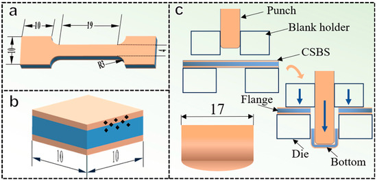
Figure 2.
Sample shape and size for mechanical testing (Unit: mm). (a) Tensile sample (b) Hardness test sample (c) Procedure and sample of deep-drawing test.
Micro-hardness measurements of the sample substrate, interface, and coating were conducted using a Vickers micro-hardness tester (HVS-1000AT, Henwaii, Laizhou, China). The load was 50 g, the loading time was 10 s, and the size of the hardness test samples is shown in Figure 2b. Nanoindentation testing was performed on the interfaces of samples using an iMicro nanoindenter (Nano-mechanics, Kla Instrument, Milpitas, CA, USA). The indentation matrix covered an area of 45 × 45 µm, with 100 evenly distributed indentation test points on the substrate.
The deep drawing test was performed on samples with specific parameters shown in Table 2. The mechanical properties of the samples were evaluated by observing the presence of cracks on the surface of the convex and concave molds, as well as inside the samples, using macroscopic and SEM methods. The deep drawing shape is shown in Figure 2c.
Table 2.
Deep drawing parameters.
3. Results and Discussion
3.1. Morphologies and Phases of Coatings
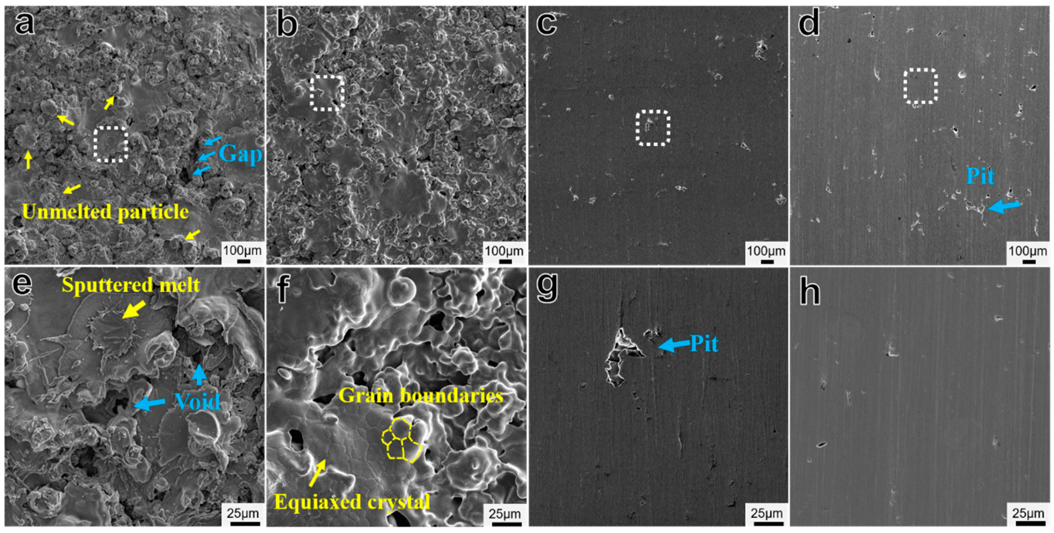
The surface morphologies of the coatings on the CSBS samples are shown in Figure 3. The As-sprayed coating surface consists of a completely melted flat morphology and a partially melted granular morphology, with voids and indistinct intervals between the solidified layers (Figure 3a). The formation of voids and gaps is attributed to the volume shrinkage of molten particles upon cooling, as well as the release of gases dissolved in the molten particles [18]. Voids and gaps, as defects, can negatively impact the mechanical properties of coatings [19]. The density of the coating is primarily influenced by the size of the molten particles. Excessive molten particles can lead to a loose, porous coating, while smaller particles tend to form a denser, more compact coating, which reduces oxidation within the coating [20]. The size of molten particles is mainly determined by spraying power, air pressure, and nozzle shape [3,21]. The coating’s morphology after the first annealing is shown in Figure 3b,f. Compared to the As-sprayed coating, the S-A coating exhibits distinct grain boundaries, revealing a completely new morphology. The presence of clear grain boundaries suggests that the coating has undergone grain recovery and recrystallization at high temperatures. At elevated temperatures, the diffusion rate of the copper atoms is enhanced, promoting the formation of recrystallization nuclei and accelerating grain growth, leading to the development of equiaxed crystals [22]. However, the gaps between larger voids and the solidified layers still remain, as they cannot be eliminated by annealing alone. The coating’s morphology after rolling shows significant changes, with no large gaps or intervals, but a smoother appearance featuring only a few pits from the rolling process. After secondary annealing, the surface morphology remains largely unchanged.

Figure 3.
Surface morphologies of CSBS coatings: (a) As-sprayed coating, (b) S-A coating, (c) S-A-R coating, and (d) S-A-R-A coating. (e–h) are the corresponding magnified images marked by white rectangular frames in (a–d), respectively.
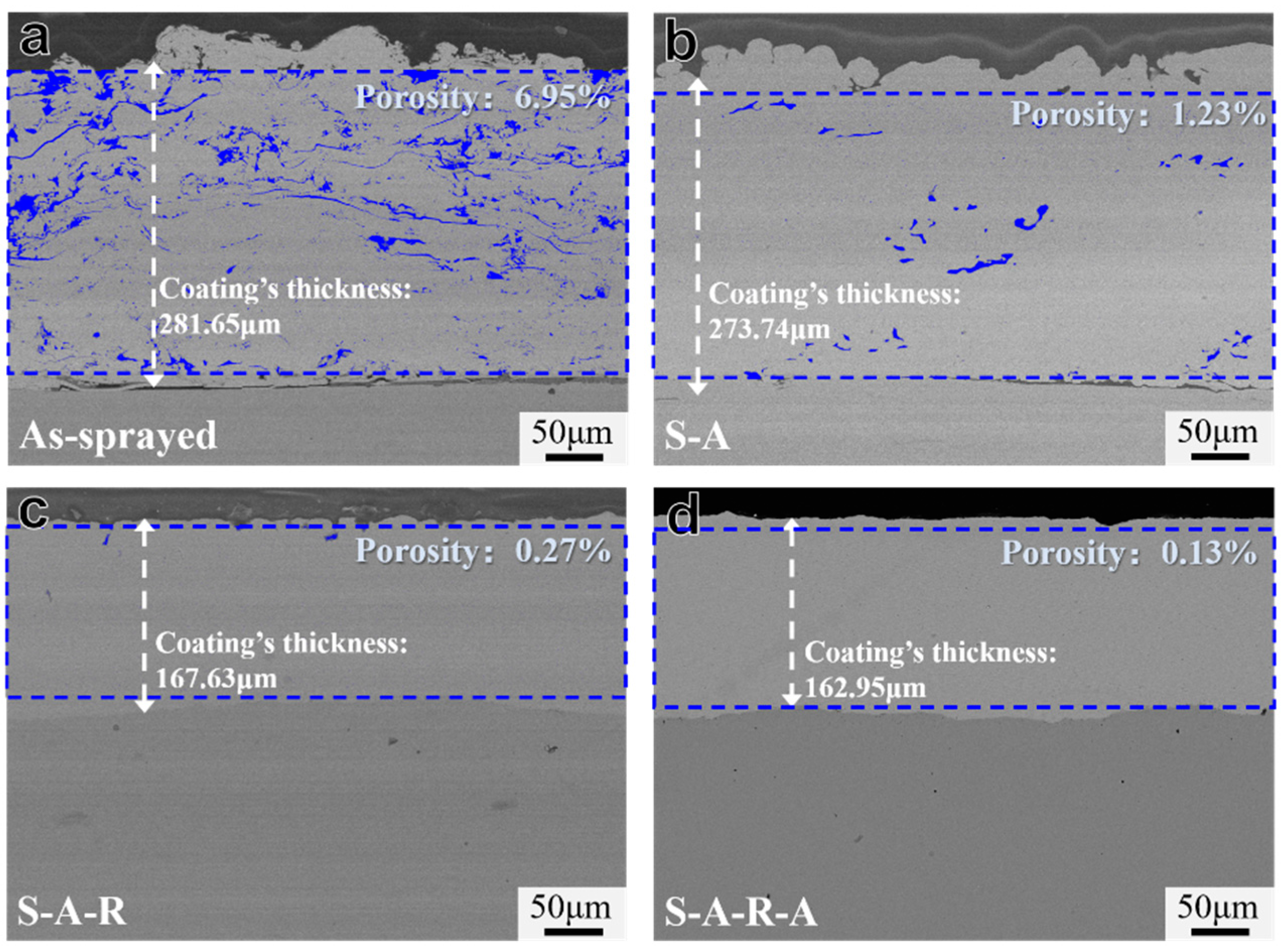
The presence of numerous voids in arc-sprayed coatings is a primary factor contributing to their inferior mechanical properties. As shown in Figure 4a,b, the As-sprayed coating exhibited substantial porosity (6.95%, marked in blue), which was significantly reduced after annealing. This improvement indicates that the Ostwald ripening of Cu grains at elevated temperatures promoted the elimination of intergranular pores through grain boundary migration. Furthermore, thermal-activated atomic diffusion facilitated stress relaxation-induced plastic flow and the partial self-healing of microcracks [23]. Subsequent rolling deformation further enhanced densification (Figure 4c,d), where residual pores were compressed and closed due to plastic strain. The final secondary annealing achieved complete pore elimination through recrystallization-driven microstructure homogenization.
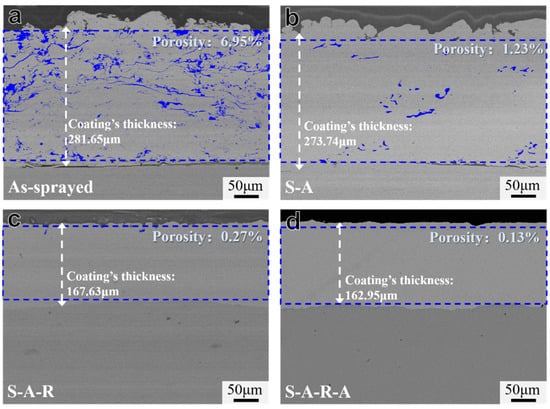
Figure 4.
Cross-sectional morphologies of CSBS coatings: (a) As-sprayed coating, (b) S-A coating, (c) S-A-R coating, and (d) S-A-R-A coating.
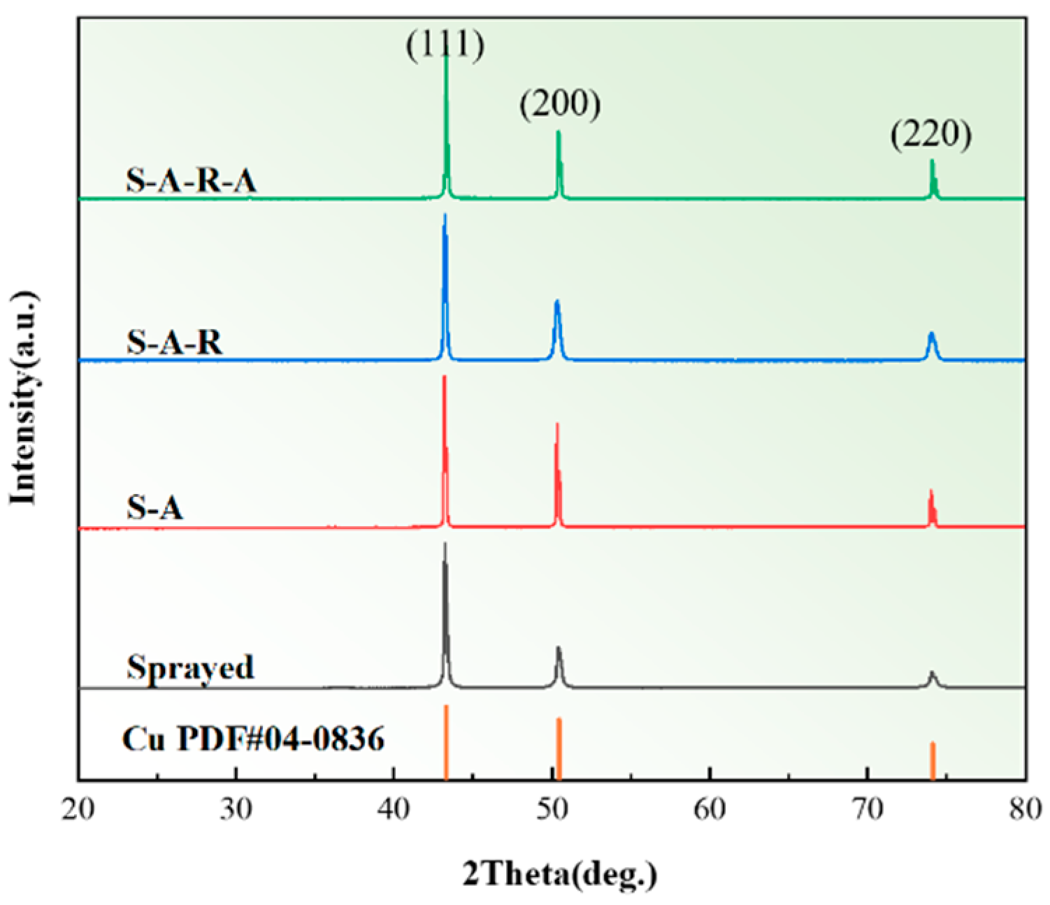
The XRD results are shown in Figure 5, and only the diffraction peaks of Cu can be identified in the coatings. This indicates that the Cu particles did not undergo oxidation or phase transition during spraying and ARA treatment. This is due to the use of N2 as the spraying gas during the spraying process and the introduction of a reducing atmosphere during the annealing process.
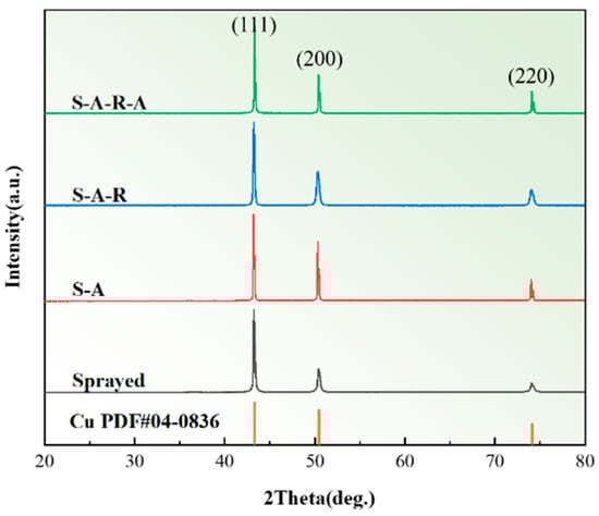
Figure 5.
XRD results of CSBS coatings.
3.2. Interfacial and Coating Microstructures
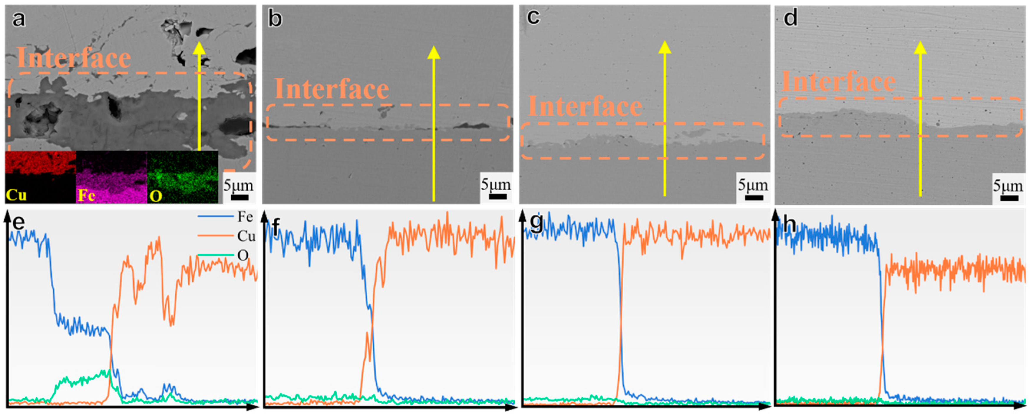
The element distribution and interface bonding morphology between the coating and substrate influence the coating’s adhesion strength [24] The SEM images and elemental distribution at the CSBS interface are shown in Figure 6. In Figure 6a, clear voids and a dark layer, approximately 10 to 20 μm wide, are visible at the interface of the As-sprayed coating. Additionally, elemental analysis revealed that copper exhibited high strength in the coating, followed by a significant decrease, while iron became active at the interface in the presence of oxygen. This result confirms the formation of an oxide film on the steel substrate during the spraying process. Furthermore, no mutual diffusion of copper and steel was observed at the CSBS sample interface, indicating that metallurgical bonding between the coatings and substrates was minimal, with the bonding mode primarily mechanical. However, as shown in Figure 6b–d, the voids at the interfaces gradually decreased with post-treatments. In Figure 6b, there are still a few narrow voids at the interface of the S-A sample, but the oxygen element is already at a low and stable level, indicating that annealing effectively reduces the oxides in the sample. The main reduction reactions are as follows:
CuO(s) + H2(g) → Cu(s) + H2O(g)
Fe2O3(s) + 3H2(g) → 2Fe(s) + 3H2O(g)
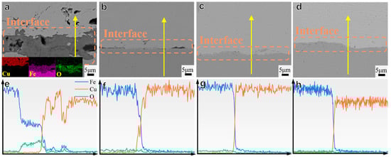
Figure 6.
SEM images and EDS results of the element distributions across the CSBS interface: (a,e) As-sprayed sample, (b,f) S-A sample, (c,g) S-A-R sample, and (d,h) S-A-R-A sample. The arrows are roads of EDS line scan paths. The inset images in (a) show the EDS mapping of the interface.
Compared to the samples before rolling, the interfaces of the S-A-R and S-A-R-A samples are more tightly bonded. The voids at the original interface were filled after rolling deformation.
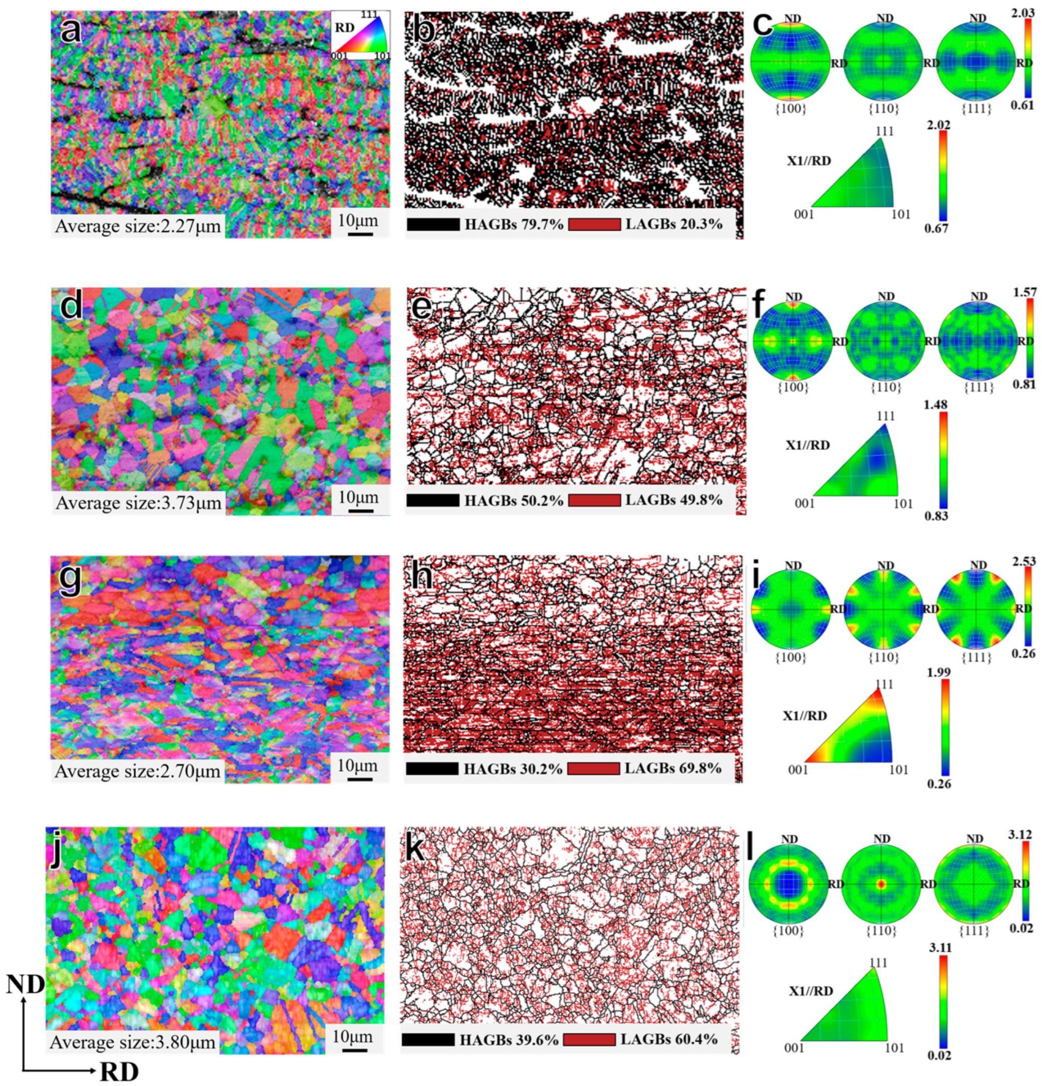
Figure 7 further reveals the effect of post-treatment on the microstructure of CSBS coatings via EBSD. The As-sprayed coating exhibits predominantly elongated grains perpendicular to the substrate, with layered stacking and no pronounced crystallographic texture. The rapid cooling of droplets upon substrate impingement suppresses equiaxed grain nucleation or growth in the melt, favoring columnar grain formation along the thermal gradient [25]. Additionally, insufficient time for crystallographic orientation adjustment under ultrahigh cooling rates induces significant differences between adjacent grains, resulting in abundant high-angle grain boundaries (HAGBs, misorientation > 10°). During annealing, the S-A coating releases residual stresses and strain energy stored in HAGBs, promoting grain boundary migration and recrystallization nucleation. This process reduces HAGBs and forms equiaxed grains [26]. The resulting random grain orientation lowers dislocation resistance, suppresses crack initiation, and significantly enhances the coating’s plastic deformation capability [27,28]. The grains in the S-A-R coating reorient preferentially toward the <001> and <111> directions, with texture intensities of 1.91 and 1.98, respectively. A strong {110}<111> texture component is also observed. As shown in Figure 7h, low-angle grain boundaries (LAGBs, misorientation between 2°–10°) dominate and concentrate in the middle-lower regions of the coating. This indicates that the mid-lower layers of the coating constitute the primary zone of plastic deformation during the rolling process, resulting in pronounced work hardening, which diminishes the strain compatibility between the coating and the substrate. As shown in Figure 7j–l, the grains in the S-A-R-A coating redeveloped a random orientation. Compared to the S-A-R coating, the aggregation of LAGBs was alleviated, facilitating dislocation slip during deformation and thereby promoting homogeneous plastic deformation of the coating.
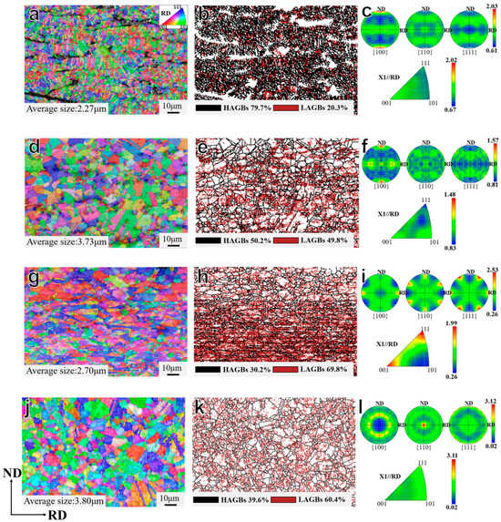
Figure 7.
OIM maps, grain boundary distributions, polo figures, and IPFs of CSBS coatings under different states: (a–c) As-sprayed coating; (d–f) S-A coating; (g–i) S-A-R coating; (j–l) S-A-R-A coating.
3.3. Micro-Hardness
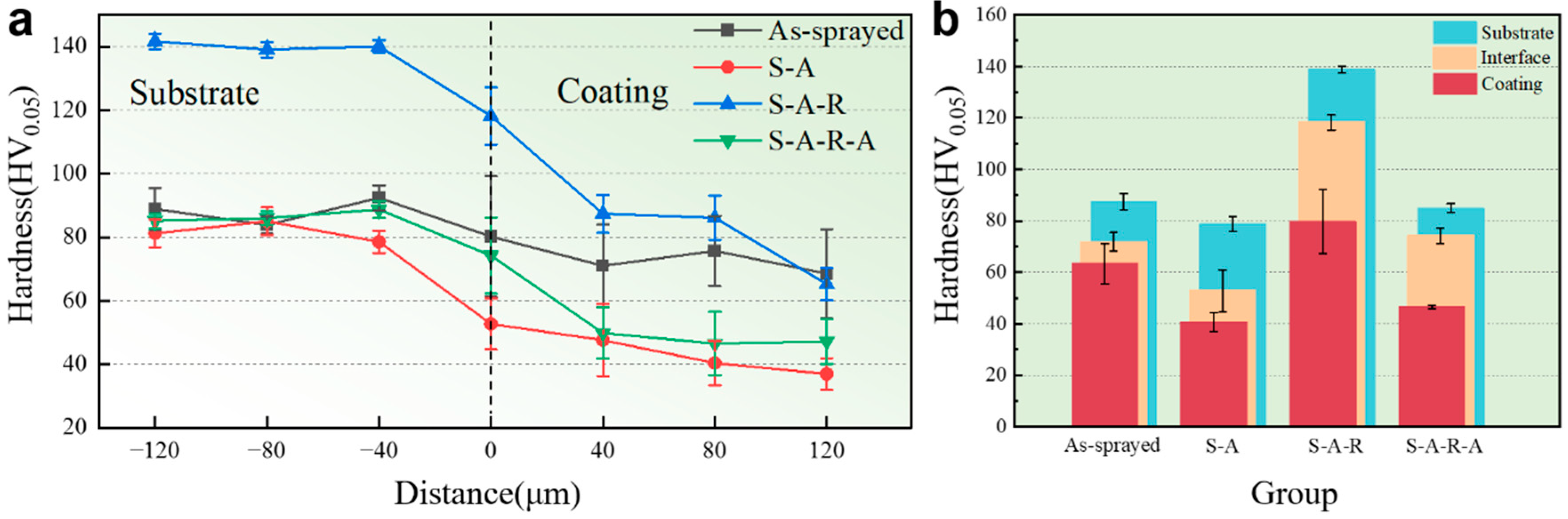
Figure 8 shows the micro-hardness depth curves of the CSBS copper coating under different states. As shown in Figure 8a, the micro-hardness of the CSBS sample decreases significantly from the substrate to the coating. The micro-hardnesses of the coatings are always lower than those of the substrates. The hardnesses of the As-sprayed and S-A-R coatings are higher than that of pure copper, while in the S-A and S-A-R-A coatings, they are slightly lower. The coatings of the As-sprayed and S-A-R samples share a common characteristic: both have undergone significant plastic deformation, leading to a pronounced work hardening effect and resulting in high coating hardness [29]. After annealing, grain refinement during heat-treatment improves the micro-hardness of the coating. However, the simultaneous reduction of oxides and dislocation density has a greater thermal softening effect, which reduces the overall hardness of CSBSs [30,31]. As shown in Figure 8b, with the progress of post-processing, the hardness distribution becomes more uniform, which benefits the processing performance of CSBSs.
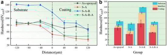
Figure 8.
Micro-hardnesses of (a) different locations at the interface of CSBS samples and (b) different regions of CSBS samples.
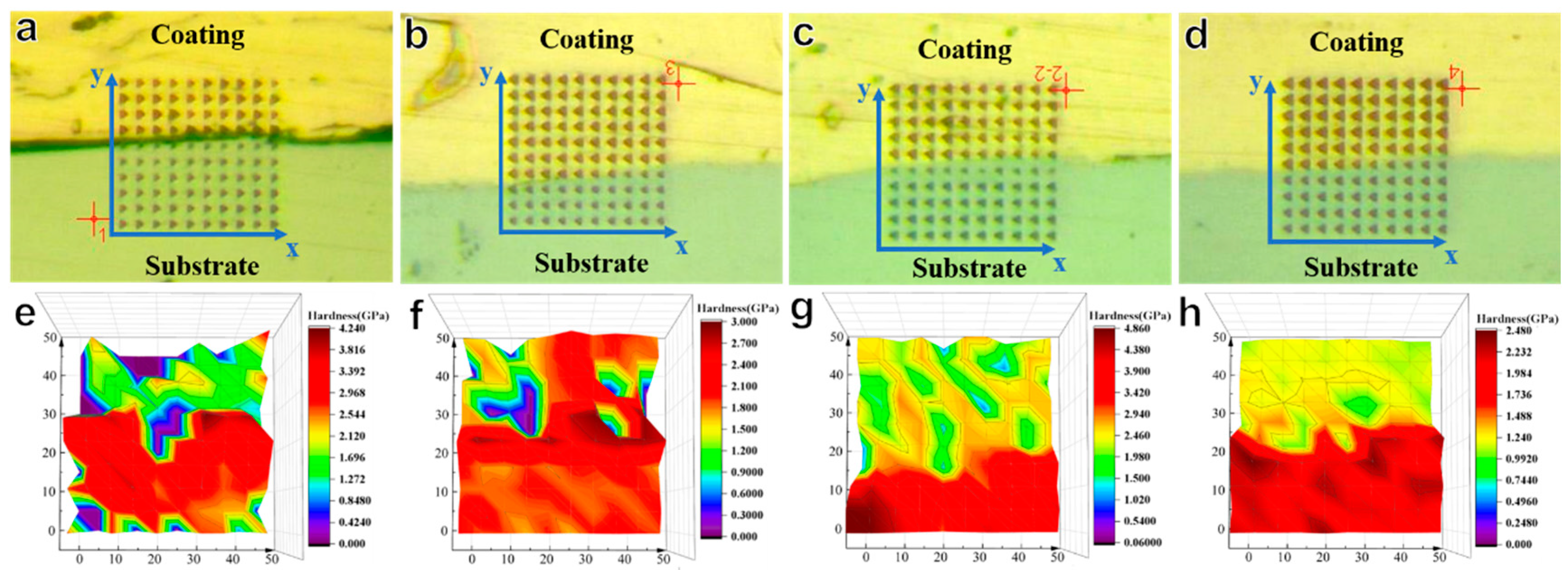
We constructed a three-dimensional hardness contour map at the interface through nanoindentation testing to reveal the mechanical properties of the CSBS substrate, interface, and coating, as shown in Figure 9a–d. Red indicates high hardness, predominantly present at the substrate and interface. The high-hardness regions in the As-sprayed interface are mainly concentrated at the interface and substrate surface, with a peak hardness of 3.79 GPa (Figure 9e). The significant hardness variation in the As-sprayed coating is primarily due to defects such as voids and a relatively higher oxide content near the interface, leading to uneven hardness distribution. After the first annealing, the overall hardness of the CSBS decreases, which is attributed to grain regrowth during the annealing process. The highest hardness is concentrated at the interface, with a peak value of 2.86 GPa (Figure 9f). Uneven hardness remains in the coating, mainly due to the presence of voids. After rolling, the overall hardness of the CSBS increases, and due to void closure, there is a significant difference in hardness between the substrate and coating. The highest hardness in the substrate is 4.84 GPa, while the highest hardness in the coating is 2.87 GPa (Figure 9g). Due to the significant hardness difference between copper and steel, the deformation after rolling also differs (copper: 45%, steel: 25%), resulting in varying degrees of work hardening in different regions [32]. After the second annealing, the overall hardness of the CSBS decreases and becomes uniformly distributed, with a maximum value of 2.47 GPa (Figure 9h). Comparing the hardness values from various points, the hardness of the CSBS after secondary annealing is the lowest, whether at the coating, interface, or substrate. This is because the higher temperature during secondary annealing results in a longer stress relief time for the CSBS [33]. The dislocations generated during deformation preferentially accumulate at the grain boundaries where the deformation is most significant, resulting in varying work-hardening effects at different locations. The variations in hardness at the same y-coordinate value can also be attributed to differences in the locations of nanoindentation points within grains, at grain boundaries, or in regions with void defects [34].

Figure 9.
Dot matrix distribution of nanoindentation at the CSBS interface: (a) As-sprayed sample, (b) S-A sample, (c) S-A-R sample, and (d) S-A-R-A sample. (e–h) are the corresponding 3D hardness distribution cloud maps in (a–d), respectively.
3.4. Fractured Morphologies of Tensile Tests
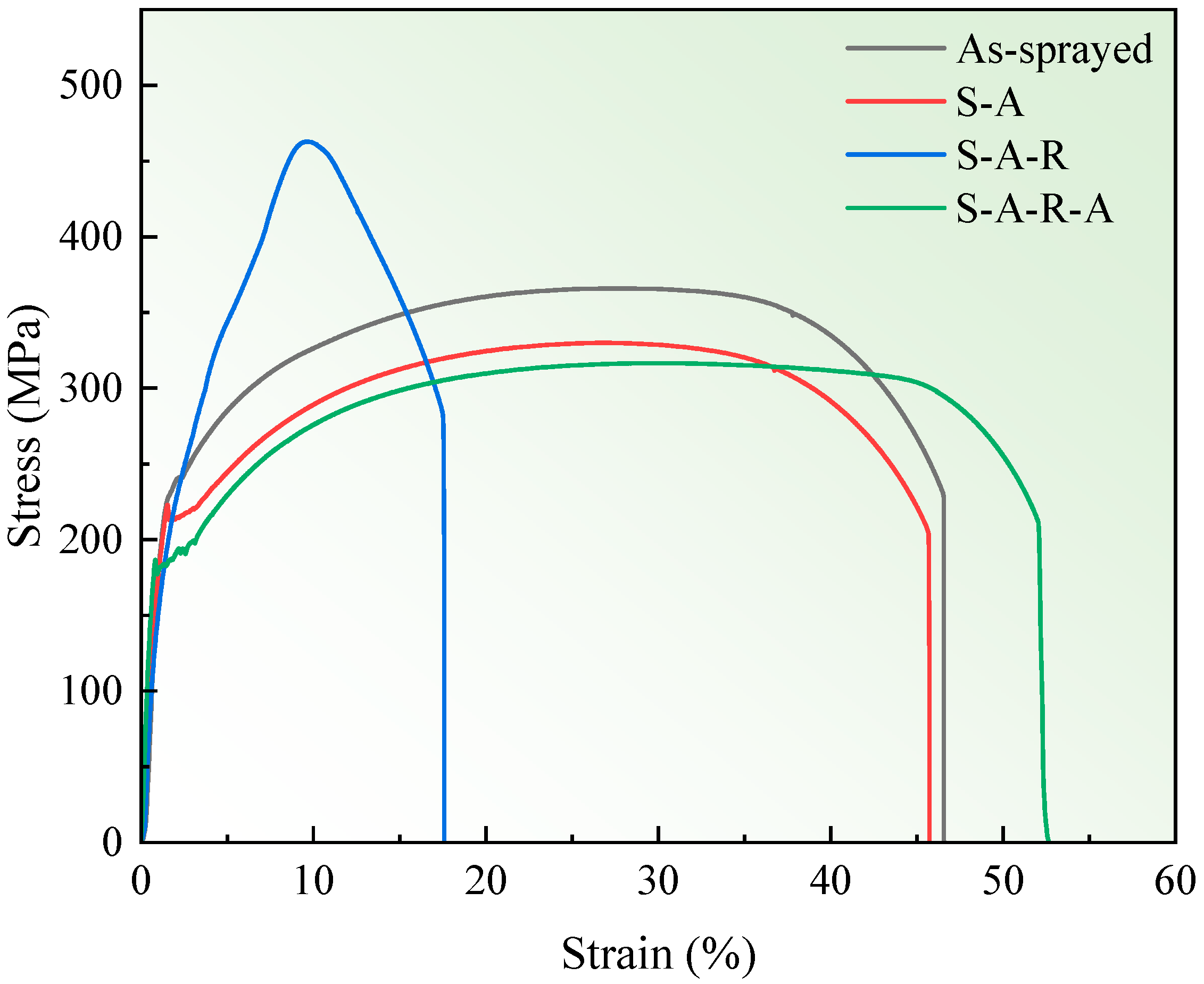
Figure 10 presents the stress–strain curves of CSBSs under different states, with a comparative analysis of curve variations to investigate the influence of ARA treatment on the mechanical properties of the substrate. After the first annealing, the substrate exhibits only a 35% reduction in ultimate tensile strength (UTS) compared to the As-sprayed state. This strength degradation is primarily attributed to dislocation density reduction and elimination of work hardening effects during the first annealing process. Subsequent cold rolling reintroduces high-density dislocations and deformation structures, regenerating work hardening effects that significantly enhance UTS while drastically reducing ductility. Following the second annealing, residual stress elimination in the substrate results in further UTS reduction and improved elongation, ultimately achieving optimal plastic deformation capacity in the substrate.
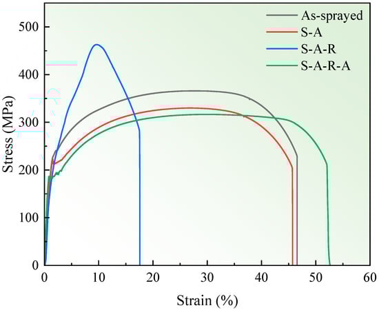
Figure 10.
Stress–strain curves of the CSBS samples.
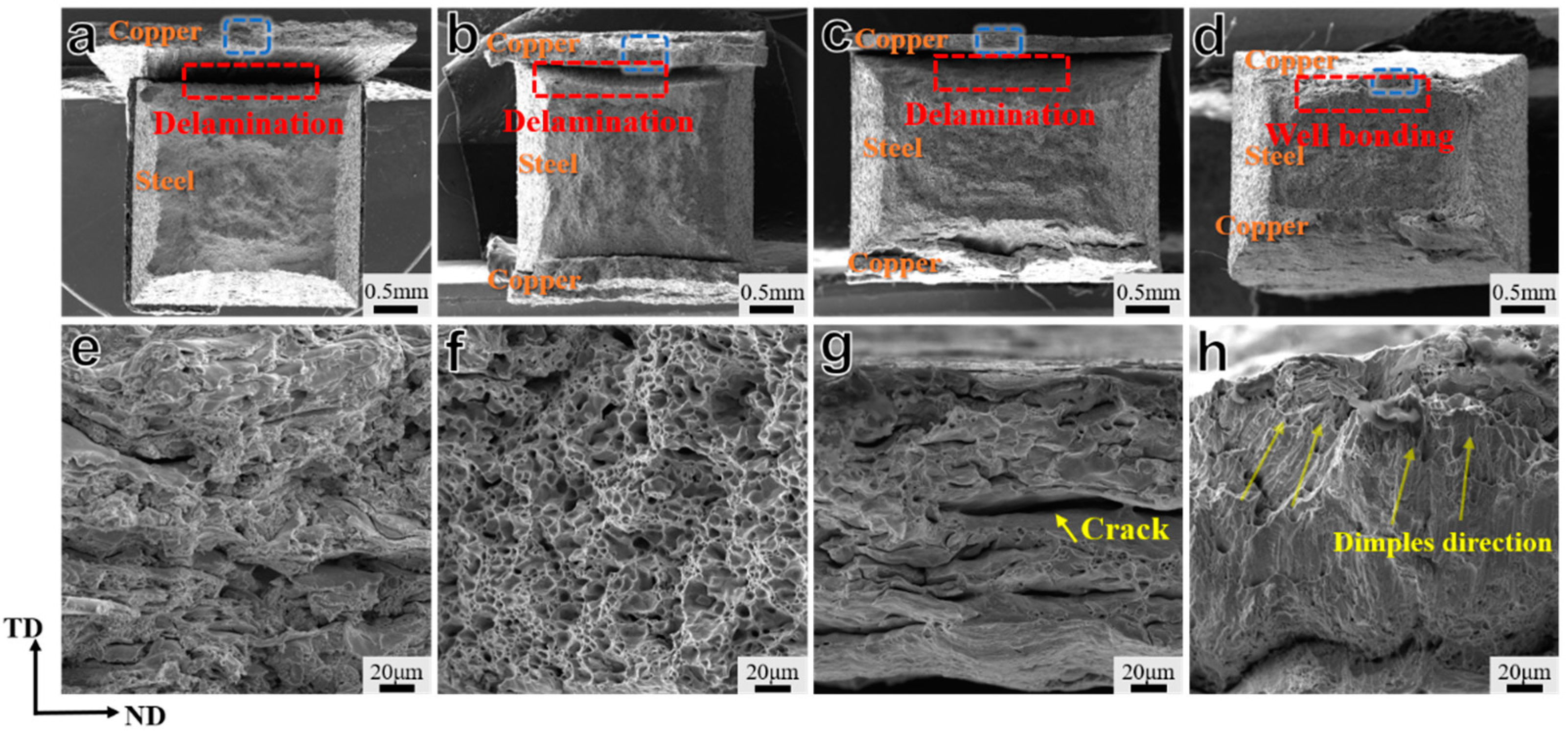
The fracture morphology of the coating reflects its plasticity and the adhesion between the coating and substrate after yielding. Figure 11a–d shows the overall morphologies of the fracture surfaces of the tensile samples and also demonstrates the adhesions between the coatings and the substrates after tensile fracture. It can be seen that, before the final annealing treatment (A-R-A), debonding always occurs between the coatings and substrates in the tensile samples. We observed the fracture morphologies of the coatings through higher magnification SEM images to explore their debonding and bonding mechanisms. The fracture of the As-sprayed coating retains its layered structure, as shown in Figure 11e. This indicates that the coating did not undergo plastic deformation before fracture, but instead, it experienced brittle fracturing and separation from the substrate under a continuous tensile force. The coating is formed by the mechanical stacking of rapidly solidified droplets during the spraying process, which results in high residual stress and the presence of hard, brittle oxides, leading to poor toughness [35]. The fracture surface morphology of the S-A coating exhibits RD-oriented dimples, a typical feature of ductile fracturing, as shown in Figure 11f. The significant difference in the size of the dimples indicates that the void boundaries within the coating are areas of preferential internal stress concentration. In these regions, microscale plastic deformation is more pronounced, and the formation and propagation of microcracks or voids are denser, leading to the aggregation of small ductile dimples [36]. The tensile fracture surface of the S-A-R coating exhibits relatively small, clustered dimples and voids, with distinct grains and a strong three-dimensional effect, as shown in Figure 11g. The fracture surface is darker in color, indicating a microporous aggregation-type intergranular fracture. Due to the significant hardness difference between the coating and the substrate, a strain distribution occurs during rolling deformation: the softer copper layer undergoes plastic deformation first, while the steel substrate remains in the elastic deformation stage. This heterogeneous deformation leads to the accumulation of geometrically necessary dislocations (GNDs) at the interface [37]. However, the accumulation of GNDs in the S-A-R coating did not result in hetero-deformation-induced (HDI) strengthening, nor did it increase the coating’s ductility. Instead, it weakened the bonding between grain boundaries, becoming the preferred path for crack propagation [38]. This is due to the voids in the softer region (coating). Cracks approximately 10 μm wide were observed in the copper layer. This is attributed to the disordered grain orientation around the voids within the coating, which results from varying stresses. These stresses hinder dislocation motion and cause accumulation at the grain boundaries. The combined effect of high-density stress and dislocations leads to crack formation. The tensile fracture surface of the S-A-R-A coating exhibits an elongated dimple morphology, with the majority oriented along the TD direction, as shown in Figure 11h. This is because the coating experiences significant shear stress during stretching, which results from both the tensile force and the bonding force between the coating and the substrate. The formation of this type of dimple indicates that work hardening in CSBSs is eliminated after annealing, leading to improved plasticity and reduced stress concentration at the interface. After the tensile test specimen fractured, the coating remained firmly attached to the substrate, without any signs of warping.
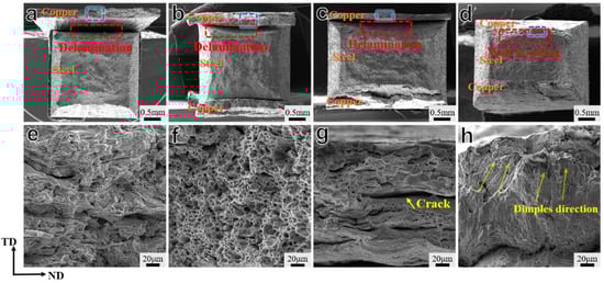
Figure 11.
Fractured morphologies of the CSBS samples: (a) As-sprayed sample, (b) S-A sample, (c) S-A-R sample, and (d) S-A-R-A sample. (e–h) are the corresponding magnified images of coatings marked by blue rectangular frames in (a–d), respectively.
3.5. Deep-Drawing Deformation Behavior
To further investigate the effect of post-processing technology on the performance of CSBS copper coatings prepared using arc spraying, deep-drawing tests were conducted on the CSBS samples. We verified the feasibility of the post-treatment process by inspecting the surfaces and cross sections of the deep-drawing samples for cracks. The deep-drawing samples of CSBSs in different states are shown in Figure 12; cup shapes are formed under high-speed impact loads. There was no earing at the mouth of any of the four deep-drawing samples. As shown in Figure 12a,e, the surface coating on the convex mold of the As-sprayed deep-drawing sample has mostly peeled off, exposing the steel substrate, with only a small amount of coating remaining on the concave mold surface. The cup mouth exhibits noticeable undulations compared to the other samples. In contrast, as shown in Figure 12b,f, the S-A coating fully adheres to the steel substrate, but more cracks are present at the bending point on the convex mold surface, perpendicular to the tensile direction. Further, these cracks are long and deep, exposing the substrate. As shown in Figure 12c,g, the S-A-R deep-drawing sample exhibits a smooth coating surface due to rolling. However, both the coating and substrate show severe failure, with the coating cracking after deformation and the substrate breaking at the bend. In contrast, Figure 12d,h show the S-A-R-A deep-drawing sample, where both the coating and substrate deform uniformly, and the concave and convex mold surfaces fully adhere. Additionally, the cup mouth is smoother.
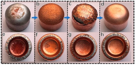
Figure 12.
Macroscopic morphologies of CSBS deep-drawing samples: (a,e) As-sprayed sample, (b,f) S-A sample, (c,g) S-A-R sample, and (d,h) S-A-R-A sample.
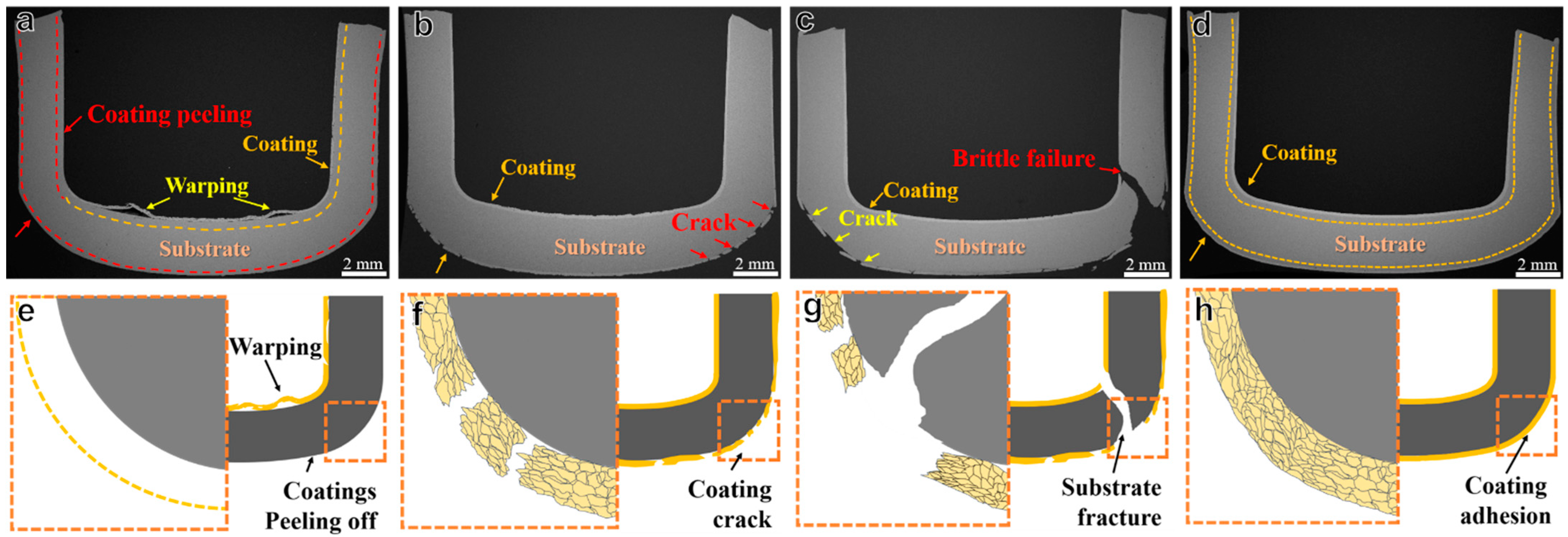
Figure 13 shows the cross-sectional morphologies of the deep-drawing samples. From Figure 13a, it can be seen that the coating on the surface of the convex mold of the As-sprayed sample peeled off under high-speed impact, while the coating on the concave mold exhibited warping. As shown in Figure 13b, the deep-drawing performance of the S-A sample was significantly improved, and the coating fully adhered to the substrate. However, many cracks appeared on the surface of the convex die, extending through to the substrate. This indicates that the voids within the coating, which cannot be eliminated by annealing, still have a significant impact on the plastic deformation properties of the coating. Because the presence of voids affects the deformation continuity of the coating, when subjected to force bending, the voids at the bending areas preferentially become areas of stress concentration, increasing the brittleness of the surrounding area and leading to cracking [39]. Therefore, rolling is used to solve the void problem inside the coating, and the roughness of the CSBS surface can be reduced to make the surface smoother and denser at the same time. However, rolling also has negative effects, as shown in Figure 13c, for the S-A-R deep-drawing sample. Deformation during rolling induces work hardening in both the coating and the substrate, leading to poor plasticity of the CSBS. The deep-drawing samples not only experienced significant cracking of the coating but also fracturing of the substrate at the bending area. Therefore, it is necessary to carry out a stress-relief annealing process. Figure 13d shows the cross-sectional morphology of the S-A-R-A deep-drawing sample; there are no more cracks or warping in the coating and substrate, and the layers have adhered to each other well.
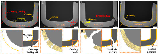
Figure 13.
CSBS deep-drawing sample cross-sectional morphologies under SEM (a–d) and schematic showing mechanisms (e–h): (a,e) As-sprayed sample, (b,f) S-A sample, (c,g) S-A-R sample, and (d,h) S-A-R-A sample.
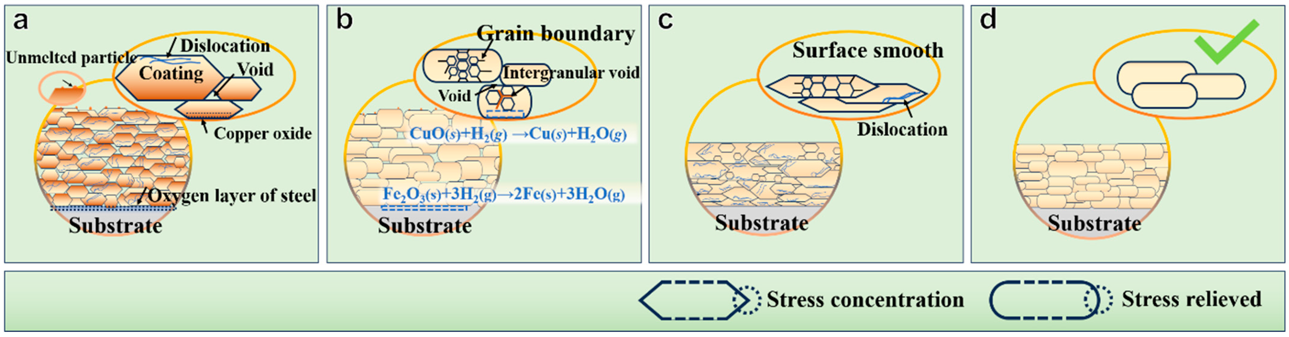
To more intuitively observe and compare the internal structures of coatings in different samples, Figure 14 illustrates the surface morphology and microstructural evolution of the CSBS coating and its post-treatment. The internal and surface characteristics of the As-sprayed coating are shown in Figure 14a. The coating contains voids and oxides, with the proportion of HAGBs reaching 92.5%. These grain boundaries accumulate a significant number of dislocations. This occurs because the coating inevitably reacts with air during the solidification process, leading to the formation of solid oxides. The oxide, with its high melting point, solidifies first, forming a hard shell on the surface of the droplet. These shells reduce the plasticity of the droplet surface, leading to the creation of voids during particle stacking and the formation of the coating [40]. Additionally, the rapid solidification of the melt prevents complete grain growth, resulting in the accumulation of dislocations [41]. Further, numerous un-melted particles are present on the surface of the sample, highlighting the rough surface characteristics typical of arc spray coatings. The internal and surface features of the S-A coating are shown in Figure 14b. Using a 3% H2-97% Ar mixture gas as the annealing atmosphere not only prevents oxidation of the sample during annealing but also effectively reduces oxide formation on the coating and interface. After sufficient recovery and recrystallization time, the coating grains grow into equiaxed crystals with distinct grain boundaries. However, the grain boundaries and the interior of the coating remain insufficiently dense due to the rapid solidification of molten particles, which introduces a high number of defects that cannot be fully eliminated by heat treatment alone. After rolling, the coating of the CSBS sample is significantly densified, as shown in Figure 14c. After rolling, the un-melted particles on the surface are flattened, resulting in a smooth CSBS surface. However, the rolling deformation leads to the accumulation of dislocations and stress concentrations (work hardening) within the CSBS. Following the second annealing, the internal stress and geometrically necessary dislocations (GNDs) at the coating interface are eliminated (Figure 14d), and the coating ultimately becomes denser, with uniform thickness and enhanced toughness and plasticity. The synergistic deformation ability of the coating and substrate is improved, and the problem of cracking during high-speed impact load deformation is solved.
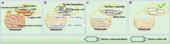
Figure 14.
Evolution and characterization of CSBS coating grains: (a) As-sprayed sample, (b) S-A sample, (c) S-A-R sample, and (d) S-A-R-A sample.
4. Conclusions
In this work, copper–steel bimetallic sheets were fabricated using a novel method of arc spray-rolling short technology. The internal bonding property of the sprayed particles in the copper coating was improved via annealing–rolling–annealing (ARA) cooperative regulation treatment. The main findings are as follows:
- (1)
- Annealing and cold-rolling synergistic treatments effectively reduce the porosity of the As-sprayed coating and improve the density of the copper coating. The voids in the coating and interface disappear after cold-rolling and two-stage annealing treatment, as well as the oxide at the interface. Tight bonds form between the copper coating and steel substrate.
- (2)
- The grain sizes of the As-sprayed coating are smaller due to the rapid cooling rate during the spraying process. The grains experience the processes of growing, elongating, and growing after annealing–rolling–annealing treatment. The results of micro-hardness testing show that a uniform stress distribution appeared in the 3D microhardness cloud map of the A-R-A sample, indicating a more homogeneous hardness distribution in the coating.
- (3)
- The ARA processing significantly improves the toughness and interface bonding strength of the coating. After tensile testing, the fractured surface of the CSBS sample displays an elongated dimple morphology with the majority oriented along the TD direction. Meanwhile, the copper coating remains firmly bonded to the steel substrate and deforms cooperatively with the substrate.
- (4)
- The copper coating of the As-sprayed CSBS sample falls off directly after deep drawing due to the low interface bonding strength, as well as the poor coating properties. In contrast, the copper coating of the CSBS sample after ARA treatment does not crack and fall off, indicating that this process results in proper hardness and toughness and a better interface bonding strength, leading to a more synergistic deformation under the deep-drawing process.
Author Contributions
Conceptualization, P.S.; Methodology, T.Y., J.B., Q.L. and P.S.; Investigation, T.Y., J.B., D.K., R.Z., Y.L., T.H. and P.S.; Writing—original draft, T.Y.; Writing—review & editing, D.K.; Supervision, D.K., R.Z., Y.L., T.H., Q.L. and P.S. All authors have read and agreed to the published version of the manuscript.
Funding
The research was supported by the Key Research and Development Program of Yunnan Province (grant no. 202303AP140016) from Peng Song, the Major Science and Technology Special Program of Yunnan Province (grant no. 202302AB080003) from Peng Song, Yunnan Fundamental Research Projects (grant no. 202401CF070146) from Dehao Kong, and Yunnan Provincial Department of Education Science Research Project (grant no. 2024J0076) from Dehao Kong.
Data Availability Statement
The original contributions presented in this study are included in the article. Further inquiries can be directed to the corresponding authors.
Conflicts of Interest
The authors declare no conflict of interest.
References
- Bazhina, A.; Konstantinov, A.; Chizhikov, A.; Bazhin, P.; Stolin, A.; Avdeeva, V. Structure and mechanical characteristics of a layered composite material based on TiB/TiAl/Ti. Ceram. Int. 2022, 48, 14295–14300. [Google Scholar] [CrossRef]
- Guo, Y.; Wu, X.; Ren, G.; Liu, Z.; Yuan, R.; Yang, X.; Dong, P. Microstructure and properties of copper-steel bimetallic sheets prepared by friction stir additive manufacturing. J. Manuf. Process. 2022, 82, 689–699. [Google Scholar] [CrossRef]
- Liang, D.; Zhou, Y.; Liu, X.; Zhou, Q.; Huang, B.; Zhang, E.; Chen, Q.; Shen, J. Wettability and corrosion performance of arc-sprayed Fe-based amorphous coatings. Surf. Coat. Technol. 2022, 433, 128129. [Google Scholar] [CrossRef]
- Daram, P.; Munroe, P.R.; Banjongprasert, C. Microstructural evolution and nanoindentation of NiCrMoAl alloy coating deposited by arc spraying. Surf. Coat. Technol. 2020, 391, 125565. [Google Scholar] [CrossRef]
- Cheng, J.B.; Liang, X.B.; Xu, B.S. Devitrification of arc-sprayed FeBSiNb amorphous coatings: Effects on wear resistance and mechanical behavior. Surf. Coat. Technol. 2013, 235, 720–726. [Google Scholar] [CrossRef]
- Tillmann, W.; Abdulgader, M.; Wirtz, A.; Milz, M.P.; Biermann, D.; Walther, F. The Effect of Argon as Atomization Gas on the Microstructure, Machine Hammer Peening Post-Treatment, and Corrosion Behavior of Twin Wire Arc Sprayed (TWAS) ZnAl4 Coatings. Coatings 2022, 12, 32. [Google Scholar] [CrossRef]
- Yuan, M.; Liu, L.; Wang, J.; Hu, Q.; Zhang, H.; Zhang, S.; Zhou, X. Crack-healing behaviour of MoSi2 dispersed Yb2Si2O7 environmental barrier coatings. Ceram. Int. 2022, 48, 29919–29928. [Google Scholar] [CrossRef]
- Ren, Y.; Tariq, N.U.H.; Liu, H.; Cui, X.; Shen, Y.; Wang, J.; Xiong, T. An innovative and flexible approach to fabricate Mg/Al composite plates: Cold spraying and hot rolling post-treatment. Mater. Sci. Eng. A 2022, 849, 143515. [Google Scholar] [CrossRef]
- Singh, R.; Schruefer, S.; Wilson, S.; Gibmeier, J.; Vassen, R. Influence of coating thickness on residual stress and adhesion-strength of cold-sprayed Inconel 718 coatings. Surf. Coat. Technol. 2018, 350, 64–73. [Google Scholar] [CrossRef]
- Zhang, X. Microstructure and Properties of Particle Reinforced Magnesium Sheet; Taiyuan University of Science and Technology: Taiyuan, China, 2020. [Google Scholar]
- Al-Ghamdi, K.A.; Hussain, G. On the comparison of formability of roll-bonded steel-Cu composite sheet metal in incremental forming and stamping processes. Int. J. Adv. Manuf. Technol. 2016, 87, 267–278. [Google Scholar] [CrossRef]
- Li, S.; Beyerlein, I.J.; Alexander, D.J.; Vogel, S.C. Texture evolution during multi-pass equal channel angular extrusion of copper: Neutron diffraction characterization and polycrystal modeling. Acta. Mater. 2005, 53, 2111–2125. [Google Scholar]
- Xu, J.; Fu, J.; Li, S.; Xu, G.; Li, Y.; Wang, Z. Effect of annealing and cold rolling on interface microstructure and properties of Ti/Al/Cu clad sheet fabricated by horizontal twin-roll casting. J. Mater. Res. Technol. 2022, 16, 530–543. [Google Scholar]
- Sun, L.; Chen, M.-H.; Zhang, L. Microstructure evolution and grain orientation of IMC in Cu-Sn TLP bonding solder joints. J. Alloys. Compd. 2019, 786, 677–687. [Google Scholar]
- Zhang, G.; Yu, J.; Su, C.; Di, C.; Ci, S.; Mou, Y.; Fu, Y.; Qiao, K. The effect of annealing on the properties of copper-coated carbon fiber. Surf. Interfaces 2023, 37, 102630. [Google Scholar]
- Kheiri, S.; Mirzadeh, H.; Naghizadeh, M. Tailoring the microstructure and mechanical properties of AISI 316L austenitic stainless steel via cold rolling and reversion annealing. Mater. Sci. Eng. A 2019, 759, 90–96. [Google Scholar]
- Li, J.; Lin, X.; Wang, J.; Zheng, M.; Guo, P.; Zhang, Y.; Ren, Y.; Liu, J.; Huang, W. Effect of stress-relief annealing on anodic dissolution behaviour of additive manufactured Ti-6Al-4V via laser solid forming. Corros. Sci. 2019, 153, 314–326. [Google Scholar]
- Ndumia, J.N.; Kang, M.; Gbenontin, B.V.; Lin, J.; Nyambura, S.M. A Review on the Wear, Corrosion and High-Temperature Resistant Properties of Wire Arc-Sprayed Fe-Based Coatings. Nanomaterials 2021, 11, 2527. [Google Scholar] [CrossRef]
- Tang, Z.; Guo, L.; Li, Z.; Huang, K.; Zheng, T.; Sun, R. A comparative study of void characteristics on the mechanical response of unidirectional composites. Mech. Mater. 2022, 174, 104456. [Google Scholar]
- Seng, D.H.L.; Zhang, Z.; Zhang, Z.-Q.; Meng, T.L.; Teo, S.L.; Tan, B.H.; Loi, Q.; Pan, J.; Ba, T. Impact of spray angle and particle velocity in cold sprayed IN718 coatings. Surf. Coat. Technol. 2023, 466, 129623. [Google Scholar]
- Joshi, R.; Boesl, B.; Agarwal, A.; Thomas, T. Desktop Manufacturing of Plasma-Sprayed Coating and Computational Estimation of its Mechanical Properties. J. Therm. Spray. Technol. 2024, 33, 2686–2697. [Google Scholar] [CrossRef]
- Pan, X.-L.; Hu, X.-G.; Zhao, J.; Qiu, L. Research Progress on Evaluation Methods of Interfacial Bonding Strength of Film/Coating. Surf. Technol. 2022, 51, 50–65. [Google Scholar]
- Feng, Z.; Wang, X.; Tan, H.; Zhang, F.; Fan, W.; Wang, Y.; Fang, Y.; Wang, J.; Wu, F.; Lin, X.; et al. Effect of heat treatment patterns on porosity, microstructure, and mechanical properties of selective laser melted TiB2/Al–Si–Mg composite. Mater. Sci. Eng. A 2022, 855, 143932. [Google Scholar] [CrossRef]
- Liu, P.; Wang, X.; Chen, D.; Long, M.; Duan, H. Interface structure characterization and elements doping on interface bonding strength and tensile failure mechanism of NiCo coating/Cu matrix. Results. Phys. 2021, 30, 104883. [Google Scholar] [CrossRef]
- Liu, W.; Cheng, Y.; Sui, H.; Fu, J.; Duan, H. Microstructure-based intergranular fatigue crack nucleation model: Dislocation transmission versus grain boundary cracking. J. Mech. Phys. Solids 2023, 173, 105233. [Google Scholar] [CrossRef]
- Alaneme, K.K.; Okotete, E.A. Recrystallization mechanisms and microstructure development in emerging metallic materials: A review. J. Sci-Adv. Mater. Dev. 2019, 4, 19–33. [Google Scholar] [CrossRef]
- Li, R.; Zhou, J.; Zhang, G. A unified explanation for variation of the grain growth exponent based on grain boundary migration kinetics. J. Alloys. Compd. 2024, 976, 173159. [Google Scholar]
- Deng, Y.; Deng, C. Size and rate dependent grain boundary motion mediated by disconnection nucleation. Acta. Mater. 2017, 131, 400–409. [Google Scholar] [CrossRef]
- Li, D.; Zhang, C.; Wang, R.; Zhang, J.; Hu, R.; Zhang, Y.; Li, G.; Lu, X. Microstructure and properties evolution of Co06/Ni60A duplex coating on copper by plasma cladding, Surf. Coat. Technol. 2022, 429, 127978. [Google Scholar]
- Gallet, J.; Perez, M.; Guillou, R.; Ernould, C.; Le Bourlot, C.; Langlois, C.; Beausir, B.; Bouzy, E.; Chaise, T.; Cazottes, S. Experimental measurement of dislocation density in metallic materials: A quantitative comparison between measurements techniques (XRD, R-ECCI, HR-EBSD, TEM). Mater. Charact. 2023, 199, 112842. [Google Scholar] [CrossRef]
- Vinay, G.; Chavan, N.M.; Kumar, S.; Jyothirmayi, A.; Bodapati, B.R. Improved microstructure and properties of cold sprayed zinc coatings in the as sprayed condition. Surf. Coat. Technol. 2022, 438, 128392. [Google Scholar] [CrossRef]
- Fang, T.; Li, W.; Tao, N.; Lu, K. Revealing extraordinary intrinsic tensile plasticity in gradient nano-grained copper. Science 2011, 331, 1587–1590. [Google Scholar] [CrossRef]
- Feng, R.; Song, W.; Li, H.; Qi, Y.; Qiao, H.; Li, L. Effects of Annealing on the Residual Stress in γ-TiAl Alloy by Molecular Dynamics Simulation. Materials 2018, 11, 1025. [Google Scholar] [CrossRef] [PubMed]
- Li, C.; Li, D.; Yuan, X.; Song, P.; Feng, J.; Huang, T.; Lu, J. Effect of water vapour on preferential orientation of thermally grown oxide at 1050 °C. Corros. Sci. 2022, 209, 110737. [Google Scholar]
- Huang, J.; Chu, X.; Yang, T.; Fang, H.; Ye, D.; Wang, W.; Zhang, X.; Sun, W.; Huang, R.; Li, C.-J. Achieving high anti-sintering performance of plasma-sprayed YSZ thermal barrier coatings through pore structure design. Surf. Coat. Technol. 2022, 435, 128259. [Google Scholar]
- Wang, J.; Fu, M.; Shi, S. Influences of size effect and stress condition on ductile fracture behavior in micro-scaled plastic deformation. Mater. Des. 2017, 131, 69–80. [Google Scholar] [CrossRef]
- Jiang, S.; Peng, R.L.; Zhao, X.; Zuo, L.; Jia, N. Deformation incompatibility enables hetero-deformation induced strengthening in Ti/Nb laminates. Mater. Res. Lett. 2023, 11, 126–133. [Google Scholar] [CrossRef]
- Zhu, Y.; Wu, X. Heterostructured materials. Prog. Mater. Sci. 2023, 131, 101019. [Google Scholar]
- Qiu, X.; Qi, L.; Zan, Y.-N.; Wang, Y.-J.; Wang, J.-Q.; Du, H.; Xiong, T.-Y. In-situ Sip/A380 alloy nano/micro composite formation through cold spray additive manufacturing and subsequent hot rolling treatment: Microstructure and mechanical properties. J. Alloys. Compd. 2019, 780, 597–606. [Google Scholar]
- Lakkannavar, V.; Yogesha, K.; Prasad, C.D.; Phanden, R.K.; Srinivasa, G.; Prasad, S.C. Interfaces, Thermal spray coatings on high-temperature oxidation and corrosion applications–a comprehensive review. Res. Surf. Interfaces 2024, 16, 100250. [Google Scholar]
- Zhao, Y.; Aoyagi, K.; Yamanaka, K.; Chiba, A. A survey on basic influencing factors of solidified grain morphology during electron beam melting. Mater. Des. 2022, 221, 110927. [Google Scholar]


Disclaimer/Publisher’s Note: The statements, opinions and data contained in all publications are solely those of the individual author(s) and contributor(s) and not of MDPI and/or the editor(s). MDPI and/or the editor(s) disclaim responsibility for any injury to people or property resulting from any ideas, methods, instructions or products referred to in the content. |
© 2025 by the authors. Licensee MDPI, Basel, Switzerland. This article is an open access article distributed under the terms and conditions of the Creative Commons Attribution (CC BY) license (https://creativecommons.org/licenses/by/4.0/).