Abstract
This research investigates the application of activated tungsten inert gas (A-TIG) welding on boiler grade SA516 Grade 70 carbon steel using nano titanium dioxide (TiO2) nano flux to enhance weld penetration depth, microstructure, and mechanical properties. A unique flux application technique was devised and experiments were carried out. Response Surface Methodology (RSM) was utilized to optimize weld parameters, namely arc length, welding current, and travel speed.The selection between A-TIG and TIG welding significantly influences penetration depth, as A-TIG benefits from arc constriction and elevated current density. The welding speed is crucial for controlling heat input, whereas current and arc length enhance penetration by influencing arc force and energy distribution. Optimizing all three parameters guarantees optimal penetration and weld quality. Microstructural research revealed enhanced mechanical properties in A-TIG weldments, distinguished by acicular ferrite in the fusion zone, which augmented toughness and tensile strength (520 MPa) compared to TIG weldments (470 MPa) and the base metal (480 MPa). Although A-TIG welds exhibited reduced impact toughness (68 J) relative to the base metal (128 J), A-TIG joints had superior ductility. The findings of this research clearly demonstrate the A-TIG welding process improved the depth of penetration and mechanical strength of the weld joints.
1. Introduction
SA516 Grade 70 carbon steel is widely utilized in the production of boilers and pressure vessels and is renowned for its superior mechanical qualities. Its resistance to fracture enhances its durability under cold conditions. The low carbon equivalent (0.41 wt%) improves weldability, minimizing the risk of cracking and assuring structural integrity and durability in industrial applications (Patel et al. [1]).
Welding is the preferred technique for joining SA516 Grade 70, creating strong, continuous joints with superior corrosion resistance relative to fasteners or rivets. TIG welding is frequently utilized for its accuracy and superior weld quality, utilizing an electric arc and inert gas shielding (such as argon) to protect the weld pool from contamination. This technique is very efficient for thin or fragile materials, ensuring low distortion, superior control, and a polished finish, rendering it suitable for applications demanding both strength and precision.
Notwithstanding its benefits, TIG welding has limitations, especially regarding penetration depth. A single pass on square-edged butt joints attains around 3 mm of penetration, making repeated passes necessary for thicker materials, hence augmenting time and cost (Niagaj [2]). Additional passes also produce more heat, expanding the Heat-Affected Zone (HAZ) and potentially modifying metallurgical characteristics. Thicker components necessitate wider root gaps and more filler material, hence raising material expenses and welding time (Paul et al. [3]).
Edge preparation for TIG welding, especially for thicker materials, is laborious and time-consuming. ISO 9692-1:2013 mandates beveling or grooving to reduce joint thickness at the root, thereby ensuring adequate weld penetration [4]. This procedure, however, increases workload, extends welding duration, and escalates total expenses (Thilipkumar et al. [5]).
Activated TIG (A-TIG) welding was developed to address these limitations, involving the application of a thin coating of activating flux (usually oxides or halides combined with solvents such as acetone or ethanol) to the base material prior to welding. This flux enhances the welding process by increasing penetration, enhancing efficiency, and reducing heat input, as a result, minimizing the Heat-Affected Zone (HAZ) and the number of required passes. A-TIG effectively reduces the limitations of traditional TIG welding, rendering it a more efficient and economical option for thicker materials (Rakesh et al. [6]).
This study examines the effect of nano TiO2 flux on penetration depth, weld microstructure, and mechanical parameters in the TIG welding of SA516 Grade 70 carbon steel. This research seeks to evaluate the potential of a novel application method for nano TiO2 flux in enhancing welding process efficiency and weld quality. The literature analysis offers a comprehensive review of the key domains relevant to our investigation, including (1) fusion welding of SA516 Grade 70 carbon steel, (2) Activated TIG (A-TIG) welding of carbon steels, (3) A-TIG welding of alloy steels, and (4) A-TIG welding of ferrous alloys using nanoparticles.
2. Literature Review
2.1. Fusion Welding of SA516 70 Gd. Alloy
Patel et al. [1] found that elevated heat input enhances hardness and tensile strength while reducing impact strength, highlighting the need of heat management. Shakya et al. [7] optimized Magnetically Controlled Gas Tungsten Arc Welding (MC-GTAW) for SA 516 Grade 70 steel, attaining a penetration of 3.92 mm and enhancing tensile strength, impact strength, and hardness by 3.16%, 22.76%, and 1.51%, respectively. Barros et al. [8] demonstrated that TIG repair passes in Metal Active Gas (MAG) welding reduced crack susceptibility, residual stress, and stabilized microhardness in ASTM A516 Grade 70 steel joints [9]. Taraphdar et al. [10] observed that several weld passes in Gas Metal Arc Welding (GMAW) heightened residual stress, which was substantially alleviated by preheating. Salah et al. [11] and Hall [12] determined that a filler metal diameter of ≤2.4 mm and a moderate welding speed optimize Submerged Arc Welding (SAW) of A516 Grade 70 carbon steel, enhancing hardness and toughness. Amanie et al. [13] established that welding speed has a greater impact on microstructure than current, influencing cooling rates and composition. These findings underscore the essential roles of welding settings, filler metal selection, and thermal control in improving welded joint characteristics.
SA516 Grade 70 possesses superior weldability, making it appropriate for the TIG, MIG, SMAW, SAW, and MAG welding techniques. Effective heat management is essential, since higher heat input improves strength and hardness while reducing impact resistance (Patel et al. [1]). MC-GTAW promotes penetration (3.92 mm) and mechanical properties (Shakya et al. [7]), whereas TIG repair welding improves bead quality and minimizes cracks (Barros et al. [8]). Preheating reduces residual stress in GMAW (Taraphdar et al. [10]). Effective heat control and parameter optimization guarantee robust, defect-free welds for pressure vessels and structural applications.
2.2. Activated TIG (A-TIG) Welding of Carbon Steels
Niagaj [2] discovered that TiO2 and SiO2 fluxes enhanced penetration by 30% to over 200%, especially in carbon and low-alloy steels. Tathgir et al. [14,15] revealed that SiO2, MoO2, and TiO2 increased penetration by 124%, with an additional 70% enhancement from 5% in argon, attributed to arc constriction and inward Marangoni convection. Kurtulmus [16] determined the ideal welding conditions, indicating that elevated current enhanced penetration, while a 0.17 TiO2 ratio at a 3 mm arc length yielded the most favorable outcomes. Rakesh et al. [6,17] established that oxides, chlorides, and fluorides elevated arc voltage, diminished arc area, and improved penetration via reversed Marangoni convection. Savytsky et al. [18] indicated that sulfur and oxygen impurities enhanced penetration by 1.3–1.5 times, whereas flux activation in high-tensile steels augmented it by 2–3 times, with oxygen having a 1.5 times more significant impact than sulfur.
Vora et al. [19,20] adjusted parameters for SA516 grade 70 steel utilizing Hybrid Teaching–Learning-Based Optimization (HTS) and the Response Surface Methodology (RSM), precisely predicting the Depth of Penetration (DOP), Heat Input (HI), and Heat-Affected Zone (HAZ).
The research shows that TiO2 flux substantially improves weld penetration in A-TIG welding of low-carbon and mild steels. Niagaj [2] documented a penetration increase ranging from 30% to 200%, whereas Tathgir et al. [14,15] ascribed an enhancement of up to 124% to arc constriction and reversed Marangoni convection. Kurtulmus [16] determined an ideal TiO2 ratio of 0.17, facilitating superior penetration at a 3 mm arc length, whereas Rakesh et al. [6,17] highlighted TiO2’s contribution to enhancing arc voltage and weld depth. Vora et al. [19,20] enhanced SA516 Grade 70 welding through HTS and RSM to forecast the Depth of Penetration (DOP), Heat Input (HI), and Heat-Affected Zone (HAZ).
These findings demonstrate that TiO2 flux serves as an effective activator for enhancing penetration, while process optimization further increases weld efficiency, and mechanical qualities, rendering it a cost-efficient alternative for high-quality welds in carbon steels.
2.3. Activated TIG (A-TIG) Welding of Alloy Steels
Arivazhagan et al. [21] investigated A-TIG welding of 2.25Cr-1Mo (P22) steel, revealing enhanced hardness and impact toughness, with post-weld heat treatment elevating toughness from 133 J to 177 J, eliminating proeutectoid ferrite, and reducing costs. Dhandha et al. [22] reported a 231% increase in penetration using MnO2 flux, however the tensile strength and impact toughness were inferior to those of conventional TIG. Paul et al. [3] and Saha et al. [23] validated the superiority of SiO2-based A-TIG welding, achieving 6.86 mm penetration and a 23% decrease in welding time for 8 mm stainless steel, whilst Saha et al. saw a 174% increase in penetration and a 70% reduction in time for 10 mm AISI-316L stainless steel. These investigations underscore the efficacy of tailored fluxes in improving weld penetration, mechanical characteristics, and process efficiency across diverse steel varieties.
Acharya et al. [24] employed the Analytic Hierarchy Process (AHP) to enhance penetration and productivity in SS 304L welding, attaining a penetration of 4.42 mm with a heat input of 2.767 kJ/mm, a pulse frequency of 160 Hz, and a welding speed of 0.5 mm/s. Sunny et al. [25] determined that welding current is the principal factor affecting penetration depth and bead width in AISI 904L plates, with RSM enabling accurate optimization. Bodkhe et al. [26] optimized A-TIG welding for SS 304L, attaining 6 mm penetration at 200 A, in contrast to 3 mm with conventional TIG, with SiO2 flux augmenting performance. Arunmani et al. [27] enhanced the fatigue strength of UNS S 32750 SDSS joints, determining that a torch speed of 69.85 mm/min and a current of 125.20 A are ideal. Korra et al. [28,29] validated the reliability of RSM in forecasting DOP in 10 mm SDSS 2507 plates, emphasizing welding current as the predominant factor. Pandya et al. [30] attained a depth-to-width ratio of 0.88 in duplex stainless steel with SiO2 flux, whereas Vidyarthy et al. [31] formulated an empirical model to forecast weld bead shape in Ferritic Stainless Steel. Joseph et al. [32] utilized a Taguchi L9 orthogonal array to enhance weld quality in AISI 4135 steel.
A-TIG welding markedly improves penetration depth, mechanical characteristics, and process efficiency in alloy steels using fluxes such as TiO2, SiO2, and MnO2 (Dhandha et al. [22], Paul et al. [3]). Optimized welding parameters, including current, torch speed, and heat input, are essential to improving weld quality (Sunny et al. [25], Korra et al. [28,29]). Furthermore, the Response Surface Methodology (RSM) has shown effectiveness in forecasting and improving welding characteristics, enabling precise control of Depth Of Penetration (DOP), heat input, and bead shape (Bodkhe et al. [26], Pandya et al. [30]). Flux-assisted A-TIG welding, when integrated with data-driven optimization, creates a strong and efficient welding method for alloy steels, rendering it a practical solution for industrial and structural applications.
2.4. A-TIG Welding of Ferrous Alloys Using Nanoparticles
Nano fluxes in A-TIG welding significantly improve weld penetration, microstructure, and efficiency. Balos et al. [33] showed that TiO2 coatings enhance weld depth by modifying Marangoni convection, shifting heat flow inward, and refining grain structure, resulting in stronger welds. Balos et al. [34] reported a 61% penetration increase with a 2% SiO2–3% TiO2 combination, reducing consumables and costs, while microstructural analysis confirmed that A-TIG promotes vertical grain recrystallization, improving weld strength. Balos et al. [35] validated A-TIG for aerospace applications, showing that TiO2 and SiO2 fluxes eliminated shielding gas needs while improving penetration, strength, and ductility, with impact tests maintaining 80–95% toughness. Balos et al. [36] demonstrated that nano–micron oxide flux particles enhanced liquid metal flow, enabling single-pass welding without filler material, achieving MIG-like productivity while maintaining TIG joint quality, particularly for thick materials. Balos et al. [37] determined that 5% SiO2 flux provided the best balance of penetration, cost, and efficiency, while higher concentrations caused flux separation and increased energy consumption. For thick steel plates, Zhang et al. [38] found that Fe2O3 nanowire flux achieved full 8 mm penetration in a single pass, doubling that of microscale flux, while also increasing joint strength to 700.7 MPa and reducing angular distortion. Tseng et al. [39] observed that SiO2 nanoparticles improved weld depth by 524% and reduced angular distortion by 78%, while Al2O3 had no effect. Afolalu et al. [40] confirmed that FeO nano flux enhanced weld depth, tensile strength, and ductility by refining the grain structure, making it superior to conventional fluxes.
Nano fluxes exceed micro fluxes in A-TIG welding by markedly increasing weld penetration, refining microstructure, and enhancing mechanical characteristics. Balos et al. [33,34,35,36,37] established that TiO2, SiO2, and Fe2O3 nanowires enhance weld depth, whereas Zhang et al. [38] achieved complete penetration of 8 mm HMS steel utilizing Fe2O3 nanowire flux, in contrast to micro-scale flux, which attained merely 4 mm. Tseng et al. [39] documented a 524% enhancement in weld depth and a 78% decrease in angular distortion with SiO2 nanoparticles. Nano flux enhances Marangoni convection more efficiently, facilitating deeper penetration and improved grain structure (Afolalu et al. [40]). Nanoparticles enhanced penetration more than submicron particles; however, a combination of nano- and micron-sized particles produced the best weld by reducing particle size through collisions between agglomerates and submicron particles, thereby effectively improving weld penetration (Balos et al. [33]). Nano flux coatings, specifically TiO2 and SiO2, facilitate vertical grain recrystallization (Balos et al. [34]) and diminish shielding gas usage and welding expenses (Balos et al. [35]). The ideal concentration of 5% SiO2 (Balos et al. [37]) achieves a balance of penetration, cost-effectiveness, and efficiency. Nano flux improves weld quality, rendering A-TIG welding a more efficient and sustainable option. This paper addresses the following research questions.
RQ 01: How does the use of nano TiO2 flux in A-TIG welding enhance weld penetration depth, microstructure, and mechanical properties compared to conventional TIG welding on SA516 Grade 70 carbon steel?
RQ 02: What is the role of critical parameters (arc length, welding current, and travel speed) in optimizing the A-TIG welding process for sustainable and efficient industrial applications?
RQ 03: How do the mechanical and microstructural improvements achieved with A-TIG welding impact its suitability and sustainability for pressure vessel manufacturing? Table 1 presents a summary of the literature in relation to the research questions.

Table 1.
Literature summary table.
3. Materials and Methods
The primary objective of this research is to investigate the impact of incorporating nano TiO2 flux on the depth of penetration, weld microstructure, and mechanical properties during TIG welding of SA516 Grade 70 carbon steel. This study explores a novel application method for nano TiO2 flux, aiming to enhance the welding process’s effectiveness. Key aspects of the research include the following:
- Depth of Penetration: evaluating how nano TiO2 flux influences the depth of penetration compared to conventional TIG welding techniques.
- Weld Microstructure: analyzing changes in the weld microstructure resulting from the use of nano TiO2 flux.
- Mechanical Properties: assessing the mechanical properties of the weld, including strength and toughness, with the application of nano TiO2 flux.
- Process Comparison: comparing the novel nano TiO2 flux TIG welding process with traditional TIG welding processes in terms of penetration depth, weld microstructure, mechanical properties, and overall process duration. Through this comprehensive comparison, the research aims to determine the potential benefits and improvements offered by nano TiO2 flux in TIG welding applications.
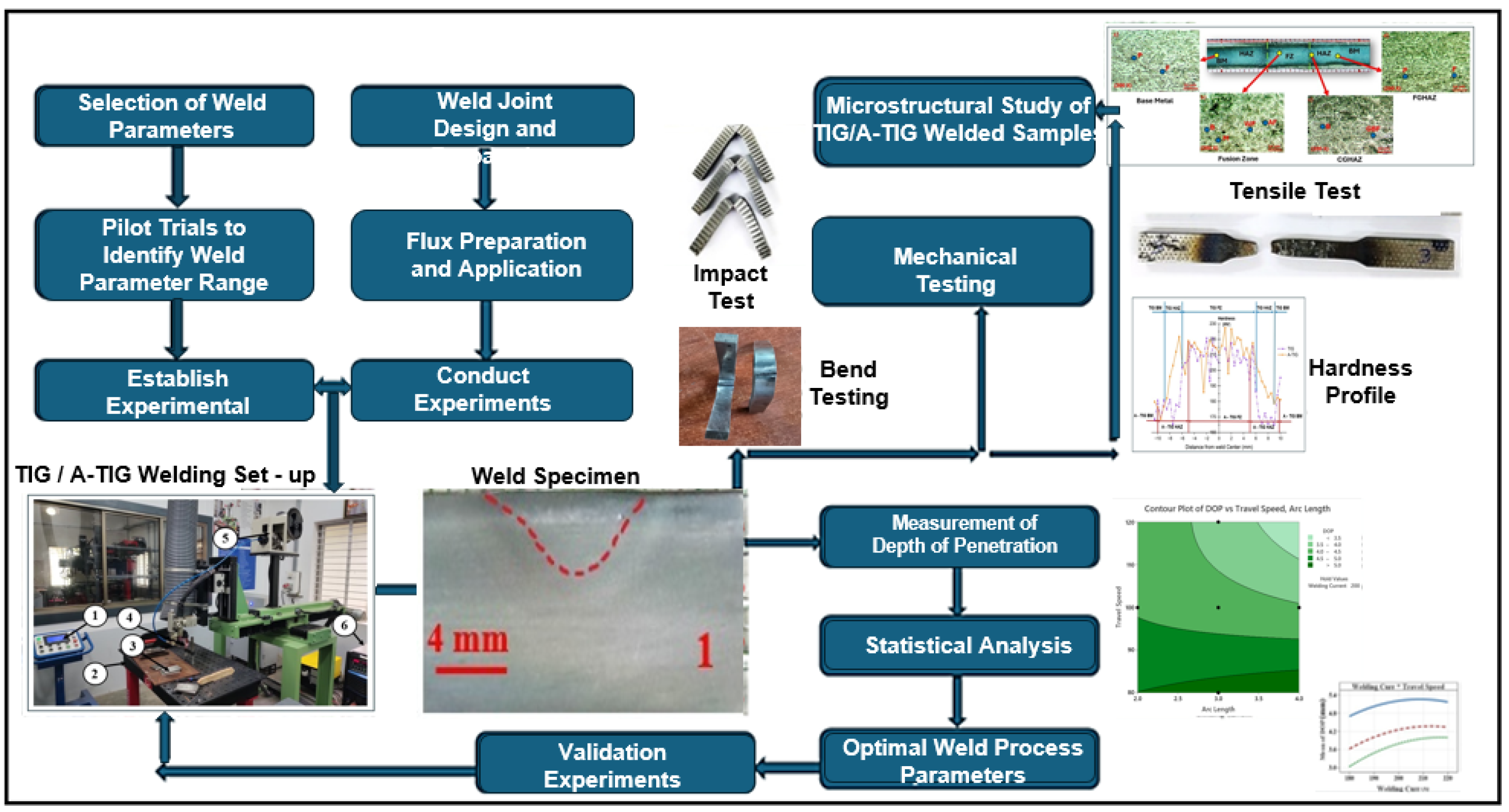
The methodology employs a systematic approach, beginning with the identification and selection of essential welding parameters, succeeded by pilot trials to determine their operational ranges. Nano TiO2 flux is applied to the substrate with a novel application method. A design matrix is created utilizing Central Composite Design (CCD) to systematically alter welding current, travel speed, and arc length. Experiments are conducted according to the CCD, with the response variable, depth of penetration, documented for each trial. Statistical analysis using Analysis of Variance (ANOVA) is utilized to assess the importance of individual characteristics and their interactions.
The welding settings are later improved using RSM executed in Minitab, with the objective of maximizing penetration depth. A validation experiment is performed to verify the optimized parameters. Thorough mechanical, metallurgical, and macroscopic assessments are conducted on the A-TIG weld specimens. Moreover, traditional TIG welding is performed with the same optimized parameters, facilitating a comparative assessment between the A-TIG and TIG procedures for penetration depth, mechanical properties, and weld microstructure. The methodology is provided in Figure 1.

Figure 1.
Methodology of the study.
3.1. Experimental Setup
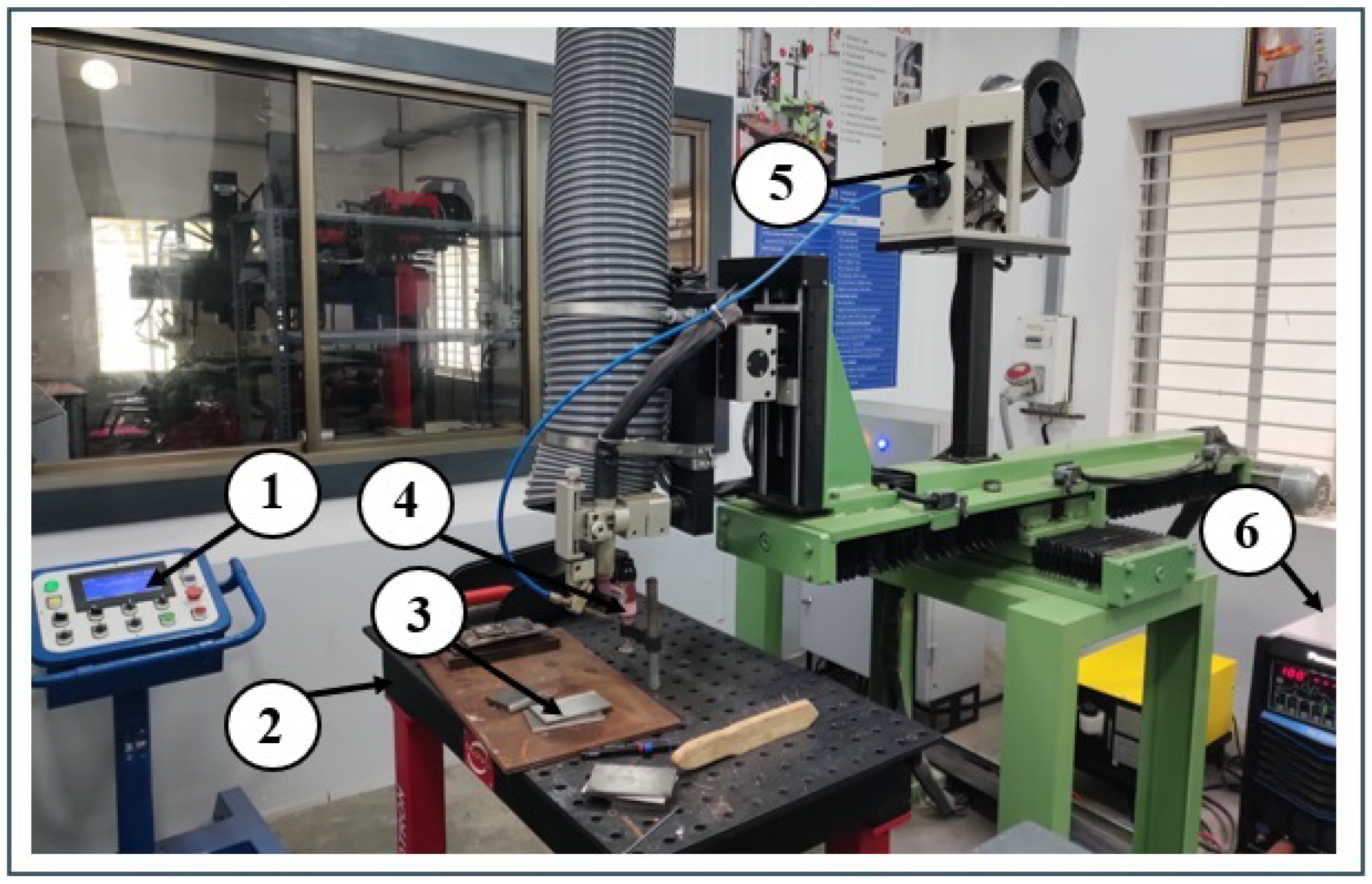
The experiment employed a Gas Tungsten Arc Welding (GTAW) Linear Welding System. Figure 2 illustrates the experimental setup. The investigations utilized SA516 70 grade carbon steel as the substrate material. The material properties are presented in Table 2. The experimental configuration included a 3 mm diameter 2% thoriated tungsten electrode, chosen for its capacity to ensure steady arc conditions and improve welding efficacy.
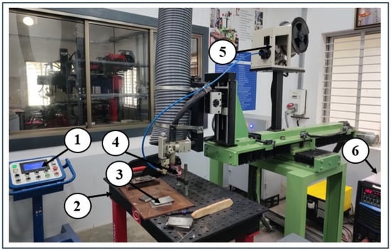
Figure 2.
TIG welding Experimental Setup. 1—Controller, 2—Welding table, 3—SA516 70 Gd. Workpiece, 4—Welding Torch, 5—Filler wire, 6—Welding machine.
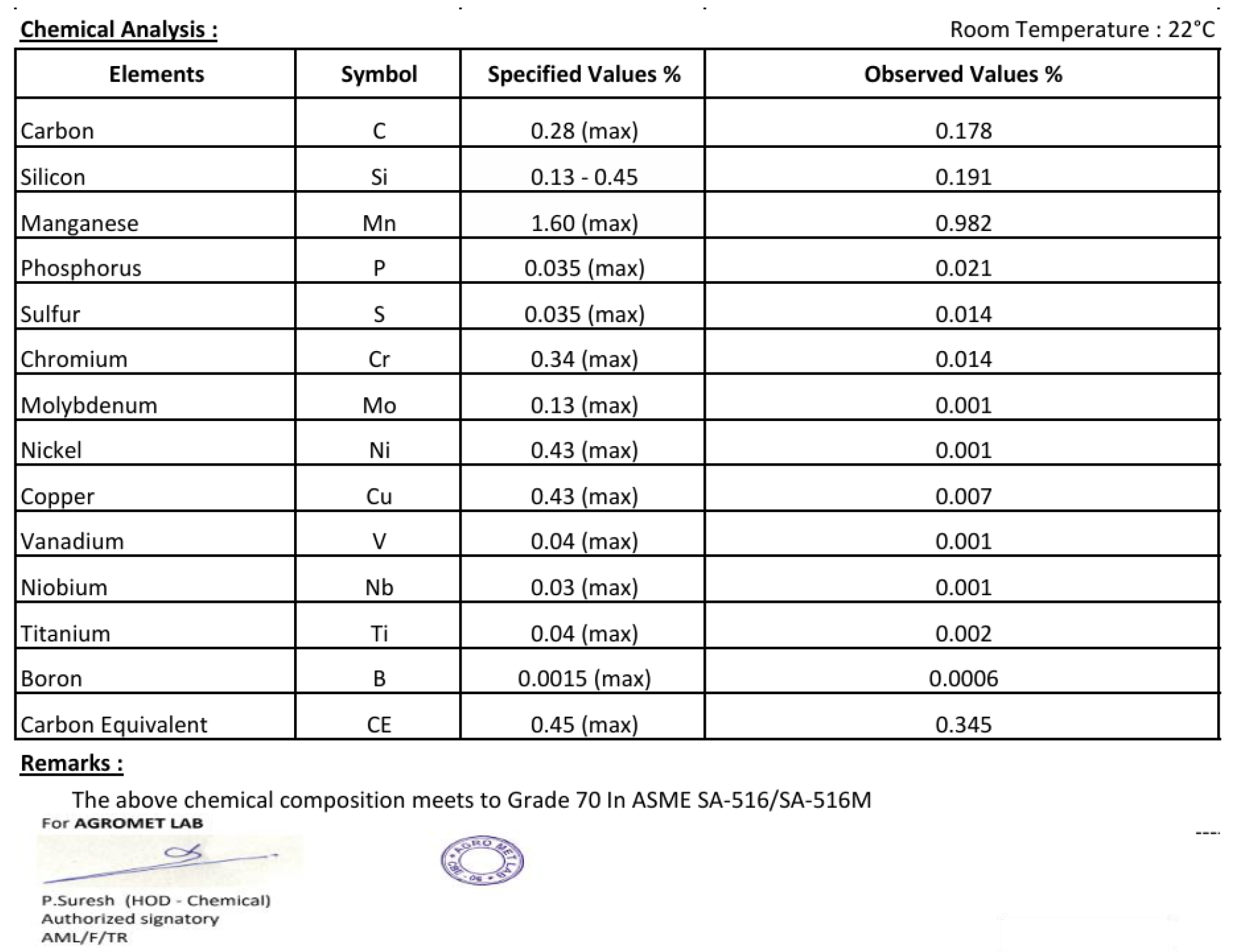
Table 2.
Chemical composition (% wt) of base metal SA 516 Gr 70 Carbon Steel (Figure A1).
The electrode tip was angled at 60°, and the torch was oriented at a 90° angle to the surface of the SA516 70 grade carbon steel plates, guaranteeing maximum arc stability during the welding process. Argon shielding gas was delivered at a flow rate of 10 liters per minute (LPM) to ensure sufficient protection and prevent contamination of the weld pool. A nozzle of size 10 was utilized to guarantee adequate gas dispersion. The mechanical linear welding system facilitated exact regulation of the welding torch’s velocity and trajectory, thereby guaranteeing uniform bead-on-plate welds during all trials. This configuration enabled regulated alterations in welding settings and for a thorough examination of their impacts on weld quality, bead morphology, and overall efficacy. Figure 3 shows the method by which the work piece was clamped to the weld table.
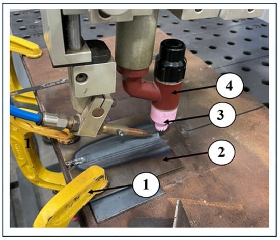
Figure 3.
Clamping method of workpiece and position of weld torch. 1—Fixture, 2—Weld Plates, 3—Nozzle, 4—Welding Torch.
3.2. Application of TiO2 Flux on SA516 70 Gr. Alloy
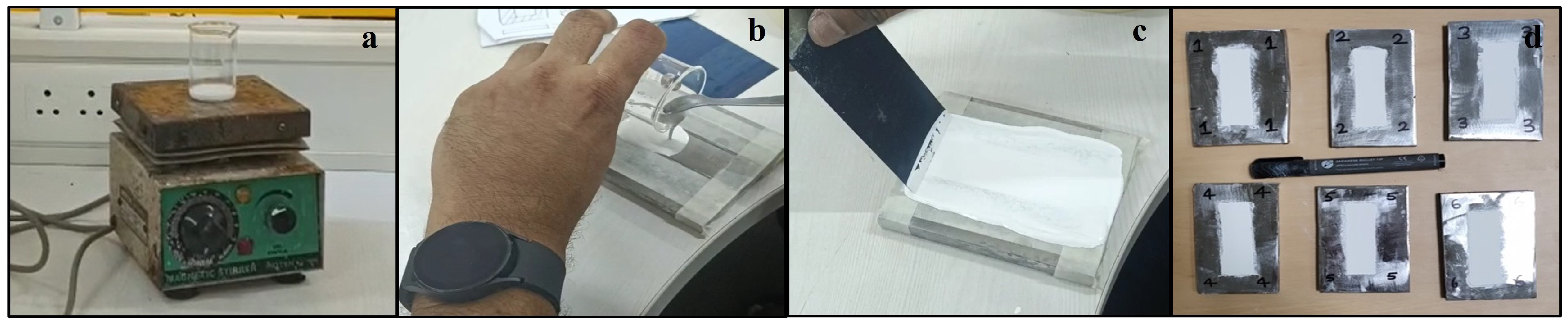
To prepare the flux mixture, 5 mL of acetone was combined with 2.5 g of TiO2 flux in a beaker. The mixture was thereafter agitated for 10 min using a magnetic stirrer to attain a homogeneous consistency. A rectangular slotted plate with a rectangular slot measuring 65 mm by 20 mm and with a thickness of 0.2 mm was firmly affixed to the base plate (100 × 75 × 10 mm) to serve as a mold for flux application. The prepared flux mixture was meticulously poured into the rectangular slot. A blade was subsequently employed to properly distribute the flux mixture across the slot, guaranteeing a uniform thickness of the flux coating over the weld area. The acetone in the combination facilitates the rapid solidification of the flux, resulting in a consistent coating throughout the weld zone. After the flux solidified, the slotted plate was detached, resulting in a pristine and uniform flux layer on the base plate, prepared for the welding procedure. The measured flux thickness was 0.15 mm. Figure 4 displays the various stages of flux application.

Figure 4.
(a) Mixing of TiO2 flux with acetone. (b) Pouring the mixture over the rectangular slotted plate. (c) Swiping the mixture with a blade for uniform thickness. (d) TiO2 flux applied on SA516 Gr. 70 carbon steel.
3.3. Welding Trials
Previous studies demonstrated that penetration depth is predominantly affected by welding factors like arc length (mm), welding current (A), and travel speed (mm/min). Consequently, these parameters were chosen for comprehensive analysis. Pilot trials were performed on SA 516 Gr 70 carbon steel sheets to ascertain the appropriate operational limits for the TIG welding process parameters. Throughout these trials, TIG process parameters such as welding current, arc voltage, travel speed, and shielding gas flow rate were methodically altered. Each parameter was independently modified while maintaining the constancy of the others, facilitating a concentrated assessment of its impact on weld quality and bead aesthetics.
After each trial, the welds underwent visual inspection and evaluation based on essential quality standards, encompassing bead morphology, penetration depth, and the identification of discontinuities such as porosity, undercutting, or incomplete fusion. The inspection results established the operational parameters for each criterion, guaranteeing minimal weld flaws, consistent arc conditions, and optimal bead properties. The established parameter ranges for experimental design were selected to enhance weld quality and reduce defect occurrence, so creating a solid basis for subsequent experimental inquiry. The input parameters and their corresponding levels are delineated in Table 3.
Table 3.
Process parameters and level.
3.4. Design Matrix Based on Central Composite Design
Central Composite Design (CCD) employing three coded levels (−1, 0, and +1) was utilized to investigate the influence of essential welding factors on penetration depth throughout the welding process. The design matrix, generated using Minitab 19 software, consisted of 20 experimental runs to systematically examine the effects of parameter alterations on welding outcomes. The trials employed diverse combinations of welding current (180–220 A), travel speed (80–120 mm/min), and arc length (2–4 mm) on SA 516 Gr 70 carbon steel sheets measuring 100 × 75 × 10 mm. The plate prior to welding was at ambient temperature. The experimental conditions were rigorously controlled according to the design matrix to yield accurate and consistent results.
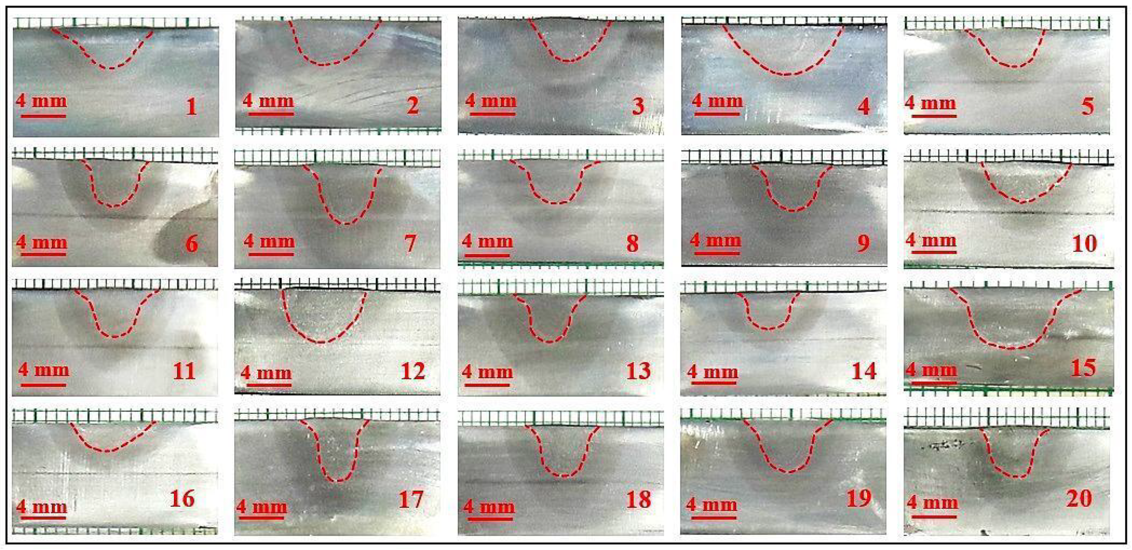
The principal objective of this strategy was to improve penetration depth by identifying the optimal combination of input parameters. The CCD approach enabled a thorough examination of the relationships between input factors and the response, providing substantial insights into the effects of welding current, travel speed, and arc duration on weld penetration. Each welded specimen was cut perpendicularly to the weld direction using a electric cutting machine. One side of the cut sample was abraded using a belt grinder, polished with various grades of emery paper using a disc polisher, and subsequently treated with alumina paste to achieve a mirror-like finish. The samples were then etched using a nital solution, including 2% ethanol or methanol and 98% nitric acid (HNO3) to reveal the weld dimensions. High-definition images were captured using a digital camera in TIFF format to obtain high-quality images. The depth of penetration was measured at the central vertical plane of the weld, aligned with the tungsten electrode axis and the welding direction. ImageJ2 software was used to quantify penetration depth, ensuring consistency across trials. The macrographs of polished and etched bead on plate samples are presented in Figure 5. The design matrix with the response is tabulated in Table 4.
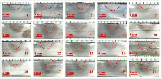
Figure 5.
Macrograph of polished and etched bead-on-plate samples used for DOP measurement.
Table 4.
Design Matrix with Response.
4. Optimization of Weld Parameters Using Response Surface Methodology (RSM)
The influence of welding parameters on penetration depth was examined by Analysis of Variance (ANOVA). The input process parameters were optimized using RSM with Minitab software. A validation trial was performed using the optimized parameters on a 6 mm thick SA516 Grade 70 carbon steel plate. The A-TIG weldment created with the ideal parameters was subjected to mechanical testing, encompassing tensile, impact, microhardness, and bend tests. To maintain consistency, each test was conducted three times.
4.1. TIG Welding of SA516 70 Gd. Carbon Steel
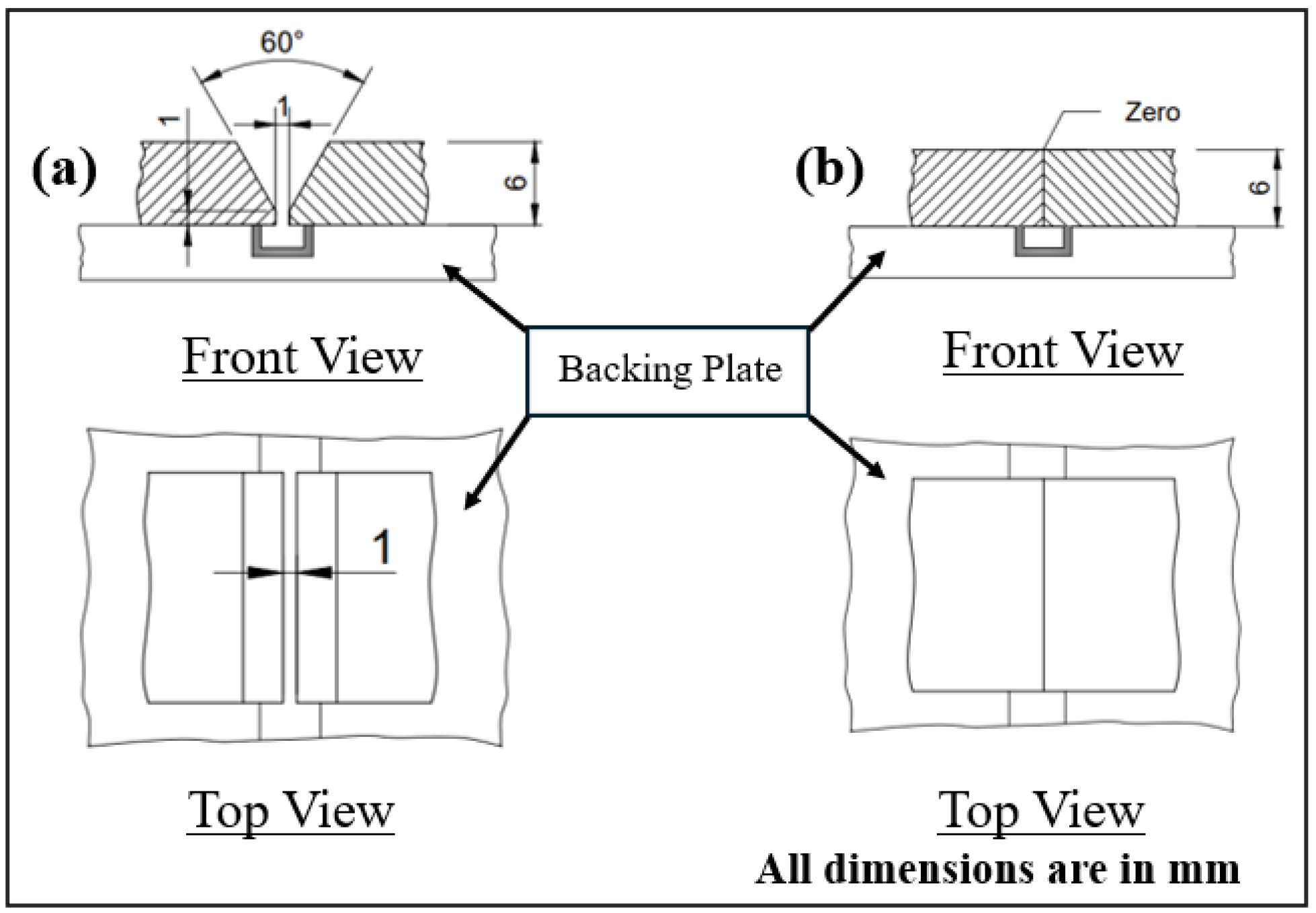
Two plates of SA516 70 Gd. carbon steel with dimensions 120 mm × 55 mm × 6 mm each were joined by TIG welding process. A weld groove with a 60° included angle was prepared using a vertical milling machine. The root opening of the test assembly was maintained at 1 mm, and a copper backing plate was used to prevent burn-through. Figure 6a illustrates the TIG weld joint configuration. The welding parameters for the root pass were as follows: welding current of 170 A, welding speed of 150 mm/min, arc length of 3 mm, gas flow rate of 12 L/min, filler wire ER70S-6 with a diameter of 1.2 mm, and a filler wire feed rate of 200 mm/min. For the two subsequent passes, the welding parameters were adjusted to a current of 220 A, a welding speed of 80 mm/min, and an arc length of 4 mm, based on the optimum conditions identified in the A-TIG experiment. A total of three passes were required to complete the weld.
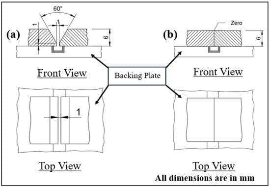
Figure 6.
(a) TIG weld joint configuration. (b) A-TIG weld joint configuration.
4.2. Mechanical Testing and Microstructural Analysis of Weldment
The TIG and A-TIG weldments were subjected to tensile test, Charpy impact test, bend test, and hardness test. Transverse tensile tests were conducted on sub-sized coupons (100 mm × 6 mm × 6 mm), fabricated in accordance with ASTM E8:8M standards, utilizing a constant crosshead velocity of 1 mm/min on a Universal Testing Machine (Fine Spavy Associates & Engineers Pvt. Ltd., Miraj, Maharashtra, India) [42]. Charpy V-notch impact tests were performed on sub-sized coupons (55 mm × 10 mm × 6 mm) fabricated via Wire Electrical Discharge Machining (WEDM) (Power Drive, Coimbatore, India) in accordance with ASTM E23-12C standards to evaluate the weldments’ behavior under impact loads [43]. The weld joint’s hardness was assessed with a Vickers microhardness tester, utilizing a 0.5 kg load for 15 s. The three point bend test was conducted based on the ASTM E190 standard to evaluate the ductility and the soundness of the weld joint [44]. Figure 7 illustrates the schematic of the test specimens in the welded joint. Metallographic characterization entailed the analysis of transverse sections (50 mm × 10 mm × 6 mm) of the weld, encompassing the base metal, HAZ, and fusion zone. The samples were carefully prepared using disc polishing with emery sheets, followed by the application of alumina paste to attain a mirror-like quality. The microstructure was exposed by etching the samples with a nital solution composed of 2% ethanol or methanol and 98% nitric acid (HNO3).
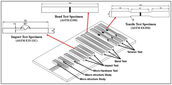
Figure 7.
Schematic of test specimens in the welded joint.
5. Results and Discussion
This section presents a comprehensive analysis of the experimental study regarding the influence of nano TiO2 flux on the penetration depth and mechanical qualities of TIG-welded SA516 Grade 70 joints. The findings are systematically delineated to underscore the impact of welding settings and flux on penetration depth, microstructural characteristics, and mechanical performance. Significant findings demonstrate the statistically validated influence of welding conditions on penetration depth, substantiated by ANOVA and optimized using RSM. Metallurgical investigations indicate microstructural transformations induced by the welding process, whereas tensile, impact, bend, and hardness assessments illustrate the enhanced characteristics of A-TIG welds relative to traditional TIG welds. A productivity analysis underscores the sustainability and efficiency of A-TIG welding, affirming its viability for industrial applications. The discussion integrates the findings with theoretical and practical viewpoints, providing a comprehensive understanding of the improvements facilitated by nano TiO2 flux.
5.1. Effect of Weld Parameters and Flux on the Penetration Depth
Minitab software is used to understand the significance of the main, second-order, and two-way interaction effects of parameters on the response: depth of penetration. This is understood using the ANOVA table, Table 5. The significance level of the experiment is set as 95%. The determined p-value of the model is less than 0.05, indicating that the model is significant.
Table 5.
The ANOVA analysis of the DOP. The * in F-Value and p-value means not computable due to zero pure error.
From Table 5, the p values for the main effects of parameters, arc length, welding current, and travel speed are 0.041, 0.003, and 0.000, respectively, all of which are less than 0.05. This indicates that the effect of the main parameter on depth of penetration is significant. The p-value of all second-order interaction effects are greater than 0.05 indicating that all second-order interaction effects on the depth of penetration are not significant.
The p-values of the two-way interactions, Arc Length—Welding Current and Arc Length—Travel Speed, are both 0.002, indicating that the effect of the two respective two-way interactions on depth of penetration are significant. The and adjusted values of 0.9370 and 0.8686, respectively, which are close to 1, indicate the adequacy of the model.
The depth of penetration based on the mathematical model on actual factors is given by,
Arbitrary values of welding current (C), torch speed (T), and arc length (A) can be employed to verify DOP.
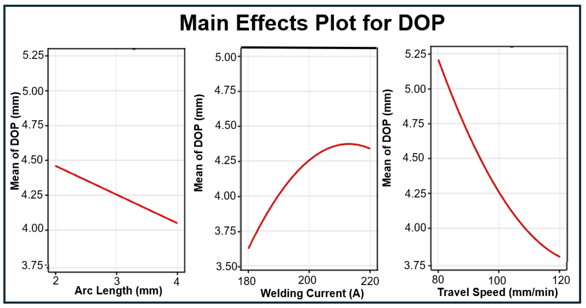
Figure 8 and Figure 9 depict the main effect plot and the interaction plot for Depth of Penetration (DOP), respectively. The correlation between arc length and DOP is linear, signifying that DOP diminishes consistently as arc length expands. The interaction between arc length and welding current significantly influences the Marangoni effect, which dictates weld penetration depth. At 180 A and 200 A, shorter arc lengths result in a more focused heat input, enhancing inward Marangoni convection and leading to deeper penetration. However, at 220 A, increasing arc length causes excessive heat dispersion, reducing the surface tension gradient that drives inward convection. This shift promotes outward Marangoni flow, where molten metal spreads laterally rather than flowing downward, leading to a decrease in penetration depth despite the higher overall heat input.
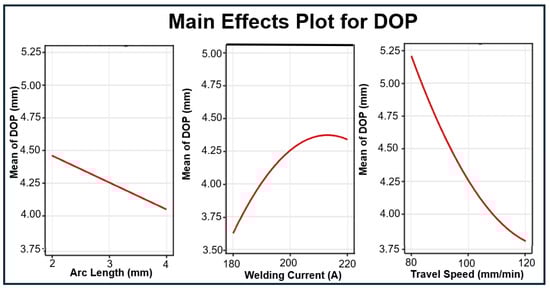
Figure 8.
Main effect plot for depth for penetration in A-TIG Process.
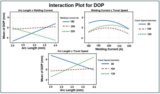
Figure 9.
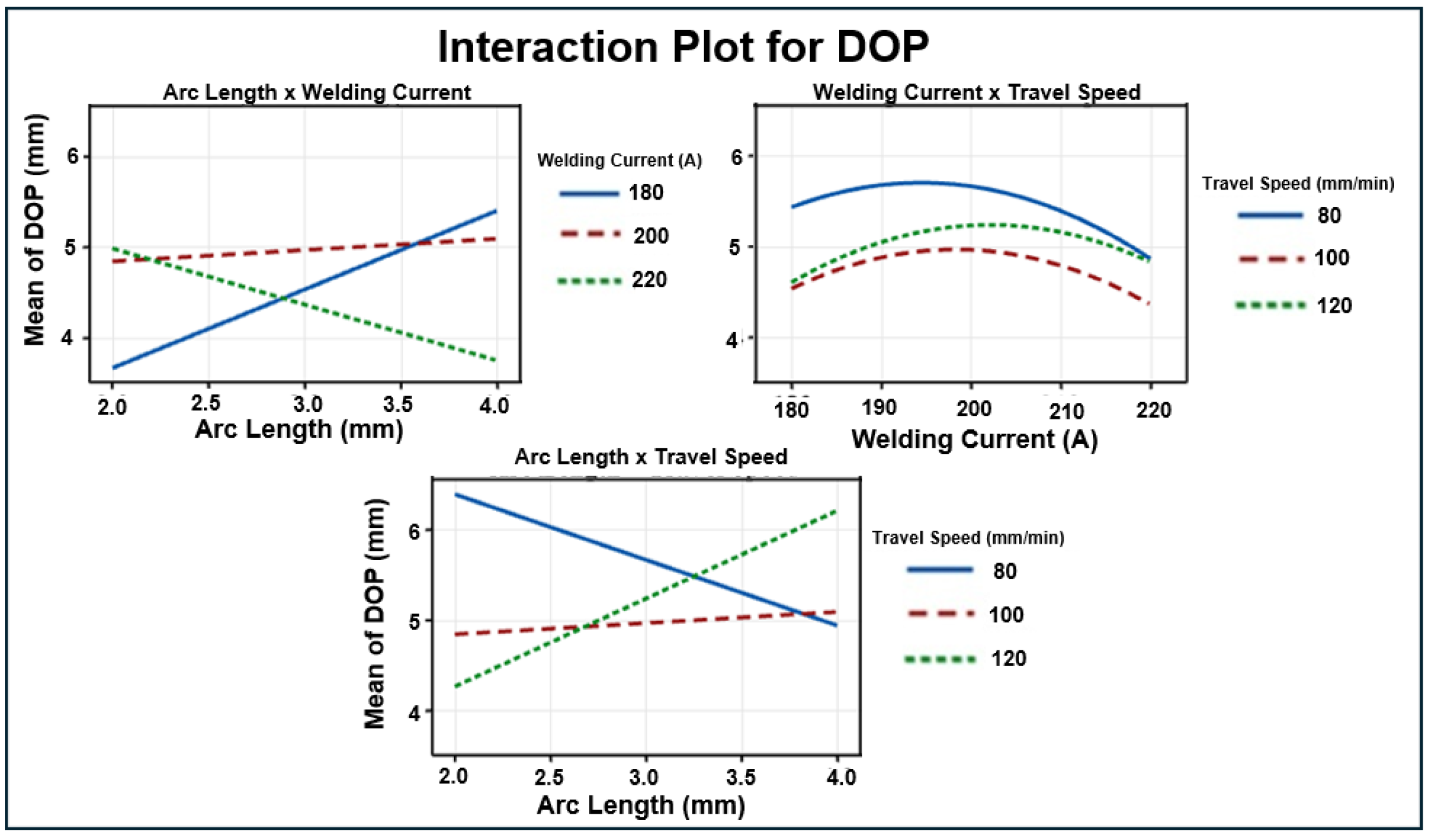
Interaction plot for depth for penetration in A-TIG Process.
Similar trends have been reported in high-current welding research, where increased arc length and energy density alter the Marangoni effect. Studies by Tsai et al. [45] and Mills et al. [46] indicate that excessive heat input can reduce inward Marangoni convection, decreasing penetration efficiency. Additionally Mendez et al. [41] demonstrated that in high-current GTAW, increased arc pressure pushes molten metal outward, forming a thin liquid layer under the arc. This layer solidifies prematurely, limiting penetration depth and increasing defects. These findings align with the observed reverse effect of arc length on DOP at 220 A in Figure 9.
The effects of welding current and travel speed on DOP are non-linear; an increase in welding current greatly enhances DOP, but a higher travel speed markedly reduces DOP. Figure 9 illustrates that the interaction effects between Arc Length × Welding Current, as well as Arc Length × Travel Speed, significantly influence the response.
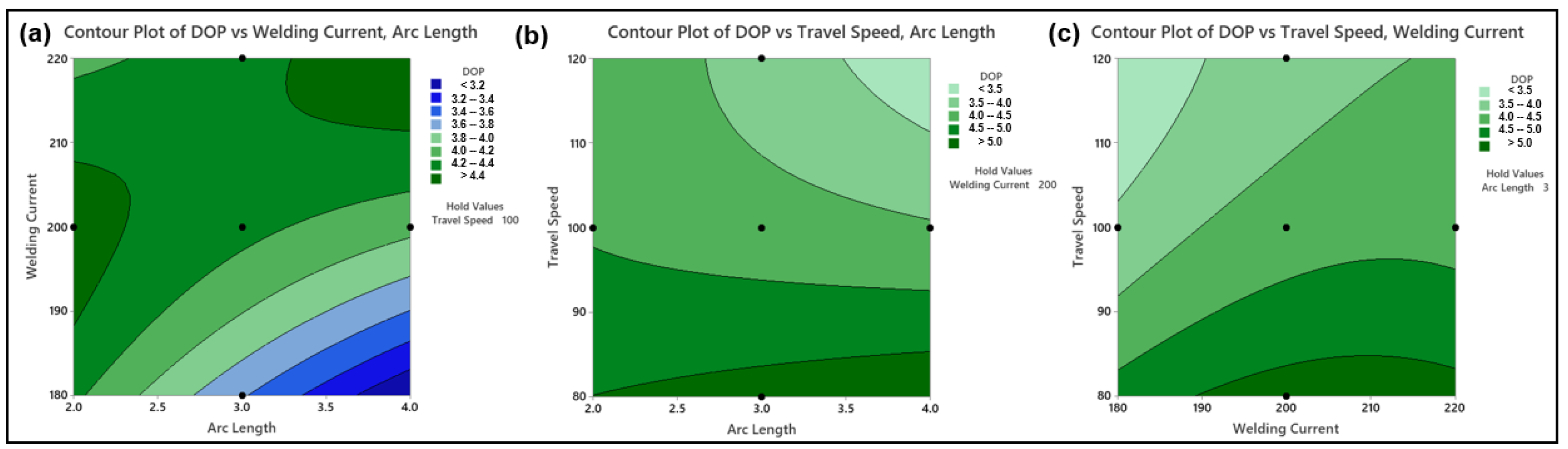
The impact of weld current and arc length on DOP is seen in the contour plot, Figure 10a. It is seen that DOP increases with increasing arc length, where the DOP is at its maximum between a weld current of 190 A to 205 A. Thereafter on increasing the weld current, the DOP becomes stable. Furthermore, it is seen that DOP increases at higher weld current and higher arc length. Figure 10b shows the impact of travel speed and arc length on DOP. It is observed that DOP increases with increasing arc length, whereas travel speed shows an inverse trend with respect to DOP. Figure 10c shows the influence of travel speed and welding current on DOP. DOP increases with increase in weld current. DOP increases with decreasing travel speed.
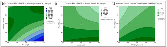
Figure 10.
(a) Contour Plot indicating the effect of Weld Current and Arc Length on DOP. (b) Contour Plot indicating the effect of Travel Speed and Arc Length on DOP. (c) Contour Plot indicating the effect of Travel Speed and Weld Current on DOP.
Based on the Design of Experiment (DOE) and RSM approaches, optimum parameters for Activated TIG welding are arrived at to achieve maximum depth of penetration. The optimum input parameters obtained are arc length of 4 mm, welding current of 220 A and travel speed of 80 mm/min for the predicted maximum depth of penetration of 5.78 mm. Confirmatory tests were conducted with the obtained optimum parameters, and a full penetration on 6 mm thick plate of SA516 Gr. 70 carbon steel using TiO2 flux is obtained. Figure 11a illustrates the application of the flux for the confirmatory test and Figure 11b shows the A-TIG welded sample produced using the optimum parameters. Figure 11c illustrates the macrograph of the A-TIG weld showing full penetration of the 6 mm plate.
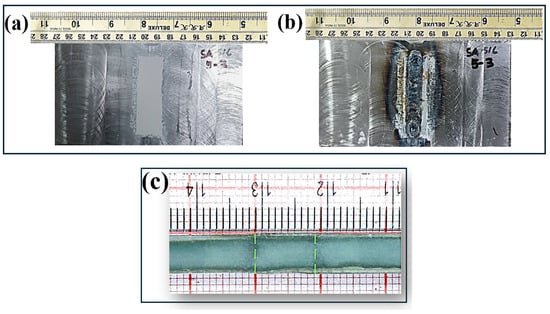
Figure 11.
(a) Flux application for validation. (b) Validated A-TIG welded sample. (c) A-TIG full penetration on 6 mm plate.
5.2. Metallurgical Analysis of A-TIG and TIG Weldments
In arc welding, microstructural alterations profoundly influence material characteristics. The welding process subjects the base metal to elevated temperatures, resulting in melting followed by rapid solidification. The rapid heating and cooling induce phase transformations in the metal, hence enhancing the grain structure and modifying the microstructure. These transitions are crucial in ascertaining the material’s ultimate properties and strength.
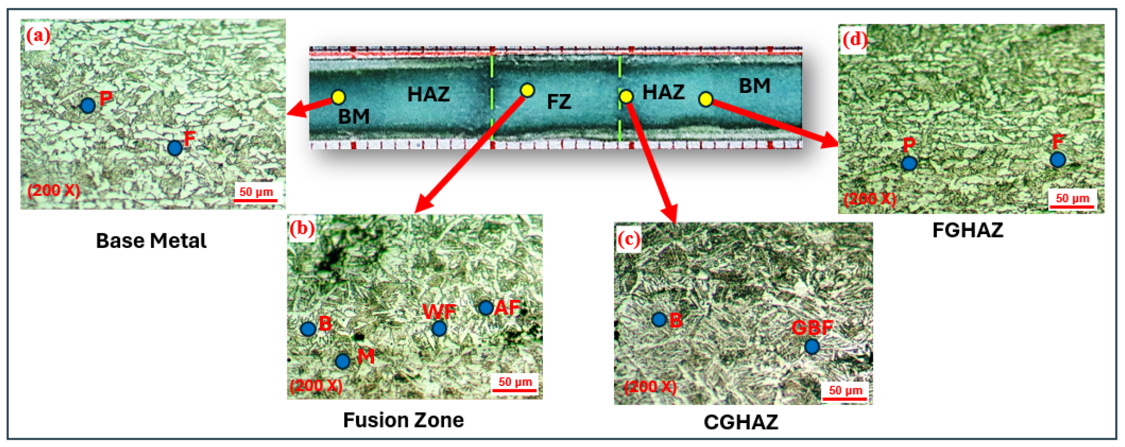
Figure 12 illustrates the microstructural evolution in A-TIG welded specimens produced at optimized welding conditions (220 A, 4 mm arc length, 80 mm/min travel speed, and 1.73 kJ/mm heat input). The welding parameters used for generating these microstructures are summarized in Table 6. The microstructure of SA 516 grade 70 base metal, illustrated in Figure 12a, exhibits a systematic arrangement of pearlite and ferrite phases inside the material. The microstructure of the Fusion Zone (FZ), Figure 12b observed in the specimen consists of a columnar ferrite configuration. It predominantly comprises acicular ferrite (AF), Widmanstätten ferrite (WF) and small amounts of Bainite (B) and Martensite (M).
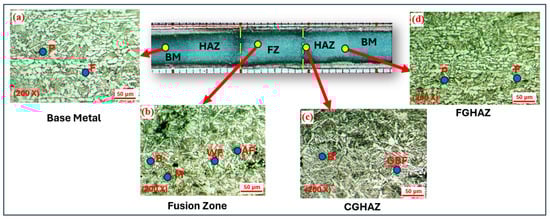
Figure 12.
Microstructures of polished and etched A-TIG weldment. (a) Base Metal. (b) Weld Metal. (c) CGHAZ. (d) FGHAZ.
Table 6.
Weld Parameters used for A-TIG and TIG welding.
The microstructure development in the coarse-grained area of the HAZ, Figure 12c, is influenced by several elements, chiefly the material’s chemical composition, the peak temperature attained during welding, and the cooling rate. The maximum temperature dictates the degree of austenite grain development, thereby influencing the grain size in this area. The cooling rate directly affects the microstructure that forms within the austenite grains as the material starts to cool. The alloy composition is essential, influencing both the grain size of the austenite and the resultant microstructural phases. Collectively, these elements influence the mechanical characteristics, strength, and performance of the HAZ. The microstructure of the Coarse-Grained Heat-Affected Zone (CGHAZ) primarily consists of a bainite mixture. Furthermore, it comprises grain boundary ferrite (GF).
The Fine-Grained Heat-Affected Zone (FGHAZ), Figure 12d, develops when the temperature remains below the threshold for grain coarsening. Furthermore, it undergoes a reduced cooling rate in comparison to the Coarse-Grained Heat-Affected Zone (CGHAZ). Consequently, this zone has a microstructure akin to the Parent Metal (PM), albeit with a finer grain structure resulting from the grain refinement process. A reduced cooling rate facilitates a more regulated transformation, resulting in smaller, more refined grains in this area, hence improving its mechanical qualities. Yang [47] and Huang et al. [48] documented similar structures in the weld.
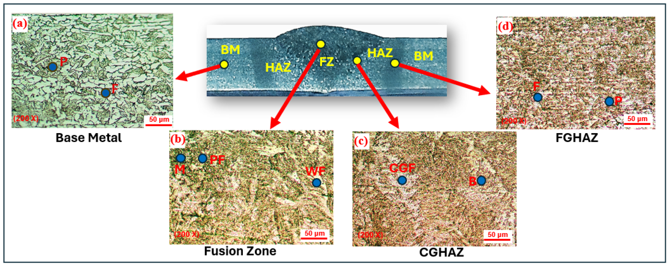
Figure 13 illustrates the microstructure of various regions within the TIG weldment, encompassing the Fusion Zone (FZ), Coarse-Grained Heat-Affected Zone (CGHAZ), and Fine-Grained Heat-Affected Zone (FGHAZ). The fusion zone, Figure 13b, predominantly exhibits a microstructure phases of Martensite (M) and Widmanstätten ferrite (WF). The CGHAZ region, Figure 13c, predominantly comprises coarsened grains, exhibiting significant characteristics of Coarse-Grained Ferrite (CGF), Bainite (B), and a little Martensite (M). In the FGHAZ area, Figure 13d, a refined mixture of fine Pearlite (FP) and Ferrite (F) is present.
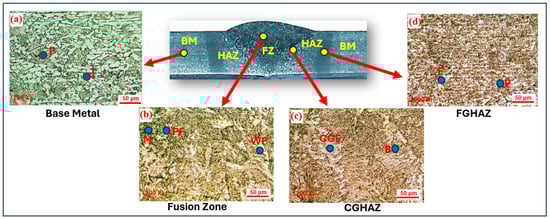
Figure 13.
Microstructures of polished and etched TIG weldment. (a) Base Metal (b). Weld Metal. (c) CGHAZ. (d) FGHAZ.
5.3. Tensile Test Results of A-TIG and TIG Weldments
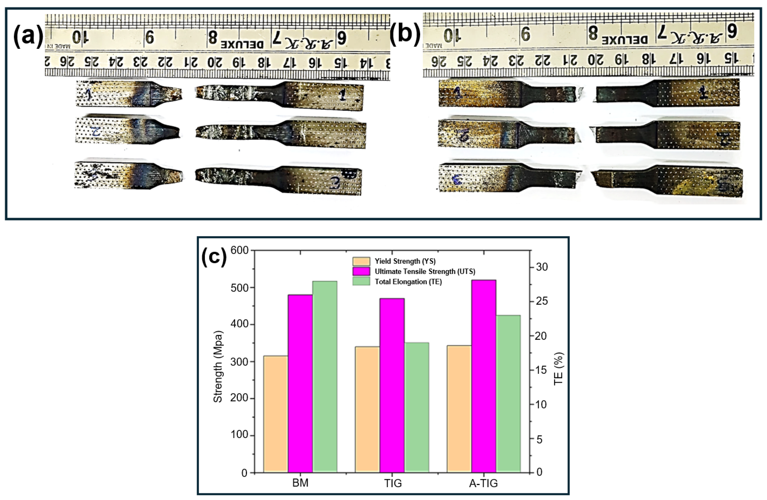
The tensile test was conducted on three distinct samples: A-TIG-welded, TIG-welded, and base metal specimens. Figure 14a,b depicts the fracture characteristics of A-TIG- and TIG-welded joints during tensile testing. The A-TIG weld sample displayed a pronounced cup and cone pattern in the fracture, indicative of ductile fractures. This indicates that the material experienced considerable plastic deformation prior to fracture. Moreover, the fracture transpired either within the base metal or at a significant distance from the fusion zone, signifying that the welds possessed commendable structural integrity and resistance to fracture propagation. The TIG weld specimen fractured at the weld interface and the failure seems to be due to shear slip, which signifies ductile fracture.

Figure 14.
(a) Tensile-tested A-TIG-welded specimens. (b) Tensile-tested TIG-welded specimens. (c) Comparison of tensile strengths.
The fracture mechanism in tensile testing of TIG and A-TIG weldments of SA516 Gr. 70 alloy is determined by their microstructures. In A-TIG weldments, the Fusion Zone (FZ) comprises Acicular Ferrite (AF), Widmanstätten Ferrite (WF), and bainite, which improve ductility and toughness by obstructing crack propagation and facilitating plastic deformation. The Fine-Grained Heat-Affected Zone (FGHAZ), characterized by refined ferrite and pearlite, enhances toughness. In TIG welding, Widmanstätten ferrite, characterized by its acicular shape, facilitates slip and plastic deformation, enabling the material to experience shear slip instead of brittle cleavage. This enables localized deformation, a defining property of ductile failure (Bhadeshia et al. [49]).
The A-TIG welded specimens exhibited superior tensile strength compared to both the base metal and conventional TIG-welded specimens. The tensile strength of the base metal was recorded at 480 MPa, but the A-TIG weld exhibited a superior tensile strength of 520 MPa and the tensile strength of the TIG-welded sample was 470 MPa. The percentage elongation of the ATIG weldment decreased to 23%, compared to 27% for the base metal. Figure 14c presents a comparison of yield strength, ultimate tensile strength, and total elongation for the base metal and TIG and A-TIG weldments.
The enhanced tensile characteristics of the A-TIG weldments compared to the TIG weldments, can be ascribed to the microstructural variations in the FZ and HAZ, coupled with optimal cooling rates and diminished residual stresses. The fusion zone of the A-TIG weldment is characterized by acicular ferrite, which imparts superior toughness and crack propagation resistance owing to its fine, interlocking structure. The TIG weldment FZ mostly comprises martensite, which is brittle, and Widmanstätten ferrite, leading to diminished ductility and toughness (Wang et al. [50], Shakya et al. [7]).
5.4. Impact Test Results of A-TIG and TIG Weldments
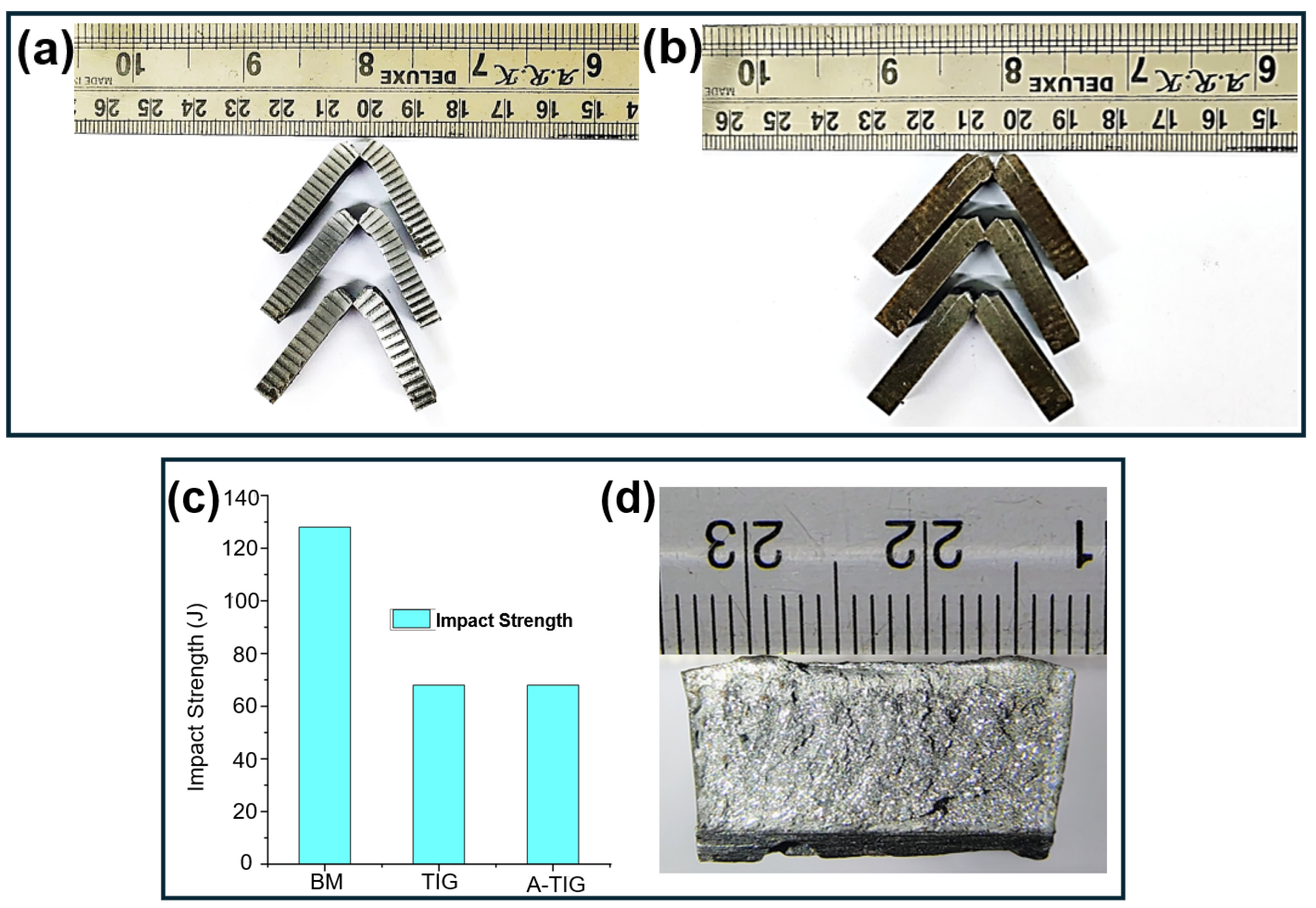
Charpy impact tests were conducted to assess the impact toughness of the specimens under severe conditions, as seen in Figure 15a,b. This test assesses the material’s ability to absorb energy following a sudden impact, providing insight into its toughness and fracture resistance. Three samples were assessed for both the base metal and the welded joints, and the average of these values was calculated to ensure accuracy and reliability in the evaluation. The impact tests were conducted at a room temperature of 30 °C.
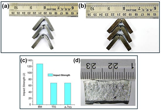
Figure 15.
(a) Impact-tested A-TIG welded specimens. (b) Impact-tested TIG welded specimens. (c) Comparison of impact strengths. (d) Macro of a fractured impact-tested specimen.
The base metal showed an impact toughness of 128 J, but the A-TIG and TIG welds revealed decreased impact toughness values of 68 J. The comparison of the impact strength of the base metal and TIG and A-TIG specimens is shown in Figure 15c. Figure 15d shows the macro of a fractured impact-tested specimen. The ferrite–pearlite microstructure of the base metal offers an optimal combination of strength and ductility, enabling it to absorb greater impact energy compared to the A-TIG and TIG weldments. In A-TIG and TIG welding, the thermal input induces thermal cycles that may result in coarse microstructures within the HAZ. Coarse bainite and ferrite in the CGHAZ diminish toughness, as coarse microstructures are typically brittle. The fusion zone in both welds comprises martensite, which enhances strength but concurrently renders the weld brittle, reducing its toughness (Manivelmuralidaran et al. [51], Wang et al. [50]).
The A-TIG and TIG samples displayed brittle fracture during the impact testing. The brittle fracture seen in the TIG and A-TIG weldments of SA516 Gr. 70 alloy during impact testing is ascribed to the microstructural characteristics of the FZ and the CGHAZ. The FZ, characterized by brittle Martensite and Widmanstätten ferrite, alongside the CGHAZ including coarse grains of Bainite and Coarse-Grained Ferrite (CGF), facilitates crack initiation and propagation. A-TIG welding improves toughness by facilitating acicular ferrite production; nonetheless, the existence of brittle phases in the fusion zone is a significant concern (Bhadeshia et al. [49]).
5.5. Bend Test Results of A-TIG and TIG Weldments
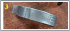
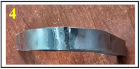
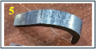
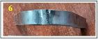
Four A-TIG-welded specimens and two TIG-welded specimens underwent a three-point bend test. The testing was conducted in accordance with the ASTM E190 standard. Among the A-TIG samples, two underwent a 180° bend at the face, while the remaining two were bent 180° at the root. In a similar manner, one TIG-welded specimen was subjected to a 180° bend at the face, while the other was bent at the root. The test results indicated that all the four A-TIG samples passed without fractures, Figure 16a,b. Both TIG-welded samples successfully passed the examination without any defects, Figure 16c. The results obtained were in accordance with the acceptance standard ASME SEC IX:2023 [52]).
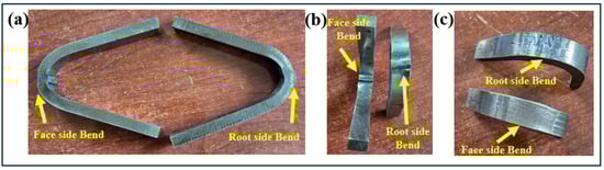
Figure 16.
(a,b) Bend-tested A-TIG-welded specimen. (c) Bend-tested TIG-welded specimen.
According to ASME Section IX:2023, a bend test is considered acceptable if defects on the convex surface do not surpass 3 mm, there are no complete fractures, and corner discontinuities are confined to 6 mm. All four A-TIG- and both TIG-welded specimens, subjected to bending at both the face and root, exhibited no fractures or flaws, thereby affirming their integrity in accordance with the ASME Section IX:2023 standard. The A-TIG and TIG samples endured an average maximum load of 1450 N and 2580 N, respectively, during the test. The detailed report of the test is provided in Table 7.
Table 7.
A-TIG and TIG bend test results.
The A-TIG-welded SA 516 grade 70 alloy has a microstructural arrangement characterized by acicular ferrite and columnar structures in the weld metal, along with grain refinement and tough phases in the CGHAZ, which collectively enhance its resistance to cracking under bending stress. The interlocking characteristics of acicular ferrite inhibit crack initiation and propagation, while the stable microstructures in the CGHAZ and base metal further augment resistance to cracking. This elucidates why the weld had no fractures even under maximum stress during the bend test.
5.6. Hardness Test Results of A-TIG and TIG Weldments
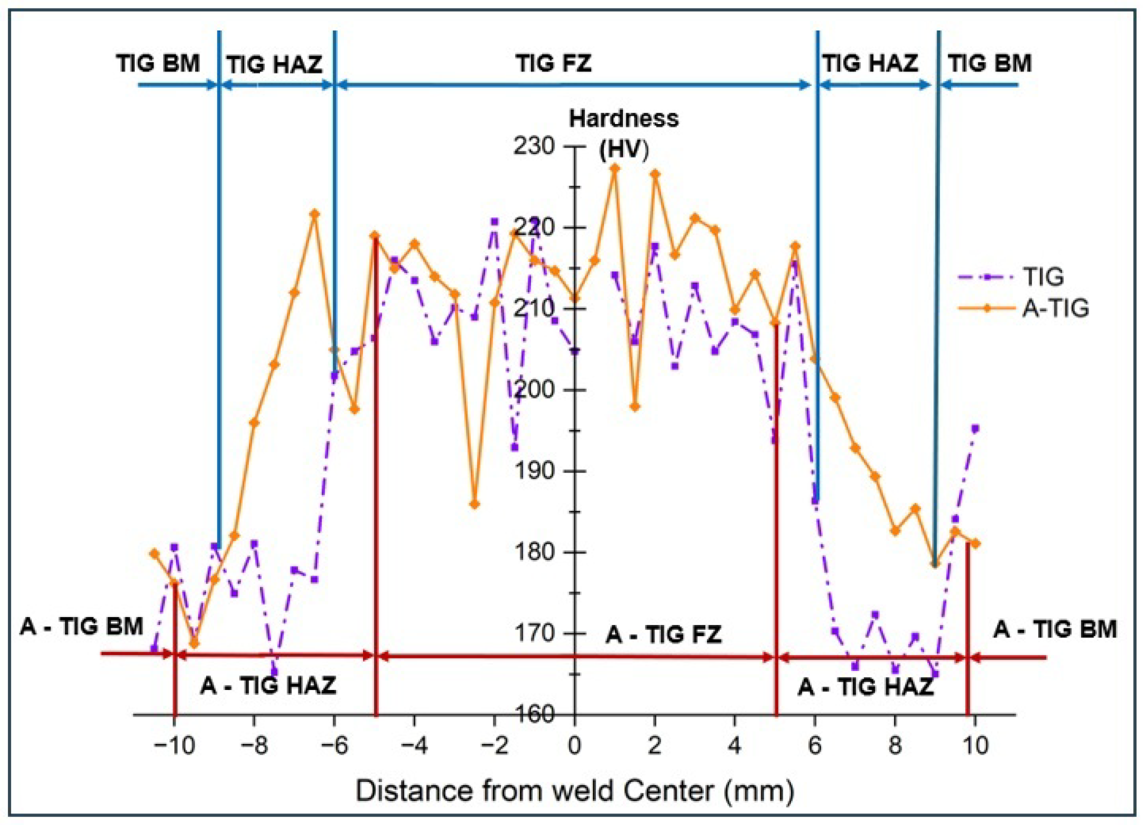
Figure 17 depicts the hardness profiles of A-TIG and TIG weldments for SA516 Grade 70 carbon steel. Hardness assessments were performed in three specific areas: the parent metal (PM), the Heat-Affected Zone (HAZ), and the Weld Metal (WM), with evaluations completed from the weld face for both A-TIG and TIG processes. The mean hardness in the fusion zone was determined to be 214 HV for the A-TIG weldment and 209 HV for the TIG weldment. The average hardness values in the heat-affected zone were 193 HV for the A-TIG weldment and 176 HV for the TIG weldment. A progressive reduction in hardness was noted as the measurements neared the base metal.
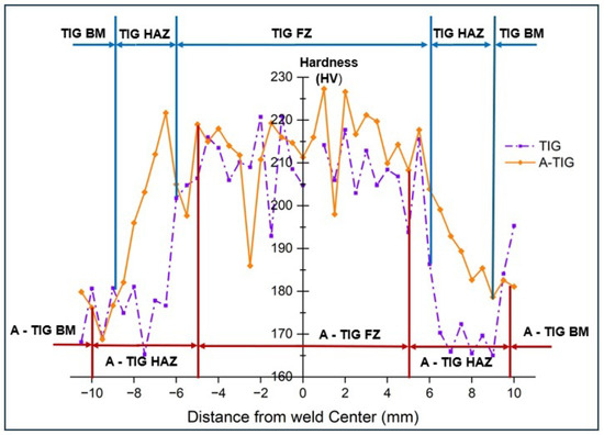
Figure 17.
Hardness Profile of A-TIG and TIG Weldment.
The enhanced hardness in the fusion zone of both the A-TIG and the TIG weldments is due to the presence of acicular ferrite. This fine, elongated microstructure markedly improves hardness by imparting strength while maintaining a level of flexibility. In contrast, the HAZ displays reduced hardness owing to the presence of coarse bainite in its microstructure. Bainite provides a compromise between strength and toughness; nonetheless, its hardness is often inferior to that of martensite. Moreover, the coarser grains in the heat-affected zone reduce dislocation density and grain boundary strengthening, thus decreasing hardness. In the FGHAZ and base metal areas, softer phases like ferrite and fine pearlite predominate. Although these phases enhance ductility, they lead to reduced hardness in comparison to tougher phases such as martensite or bainite (Aravind et al. [53], Wang et al. [50]).
5.7. A-TIG Welding: A Sustainable Solution for Improved Productivity in Welding
Industries, although acknowledging the benefits of A-TIG welding, remain reluctant to entirely adopt it as a substitute for traditional TIG welding. This hesitance arises from multiple sources, including established practices and apprehensions regarding the feasibility of extensive implementation. A-TIG welding provides significant productivity advantages. This section assesses productivity improvements based on simplified assumptions to demonstrate these advantages.
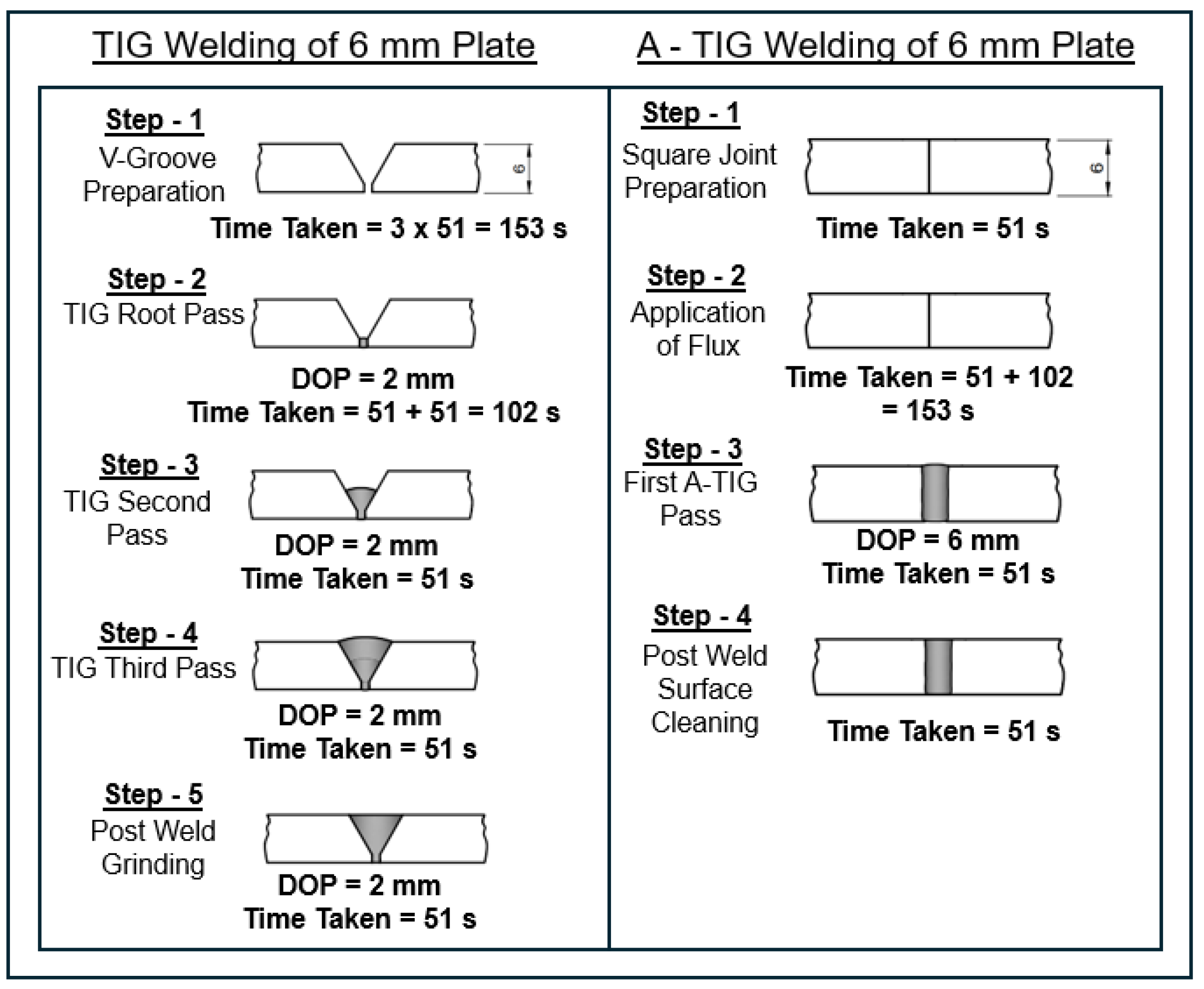
An equivalent time approach is presented in order to improve the evaluation of welding productivity (Paul et al. [3]). The duration of a single welding pass along the joint, T, serves as a benchmark. All other pertinent procedures are approximated as functions of T, so streamlining the entire analysis.
For single-sided butt welding of 6 mm-thick plates by TIG welding, a V-groove is made between the plate to be joined, Figure 18. The preparation time for the V-groove is estimated to be thrice that of a single welding pass. The plates are subsequently tack-welded at both ends to guarantee accurate alignment and placement, requiring an anticipated duration of T. The weld is completed by executing three successive TIG welding passes. Ultimately, grinding or finishing is executed to eliminate surplus weld metal and enhance appearance, which requires an anticipated duration of T. The cumulative equivalent duration for this TIG welding procedure can be expressed as:
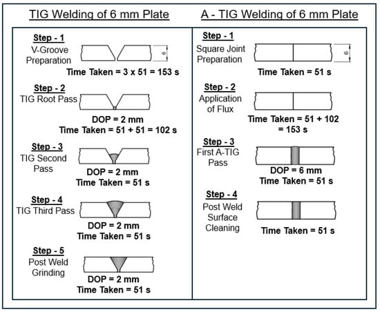
Figure 18.
Illustration of steps taken for welding 6 mm plate by A-TIG and TIG Welding Processes.
A square joint is formed between the plates while employing A-TIG welding for single-side joining of 6 mm-thick plates. The preparation of the square joint is estimated to need time T. The plates are subsequently positioned and secured using tack welding at both ends, so assuring correct orientation and alignment. The plates are positioned contiguously, Figure 18. The corresponding time is designated as T. The flux is subsequently combined with acetone and applied to the plate’s surface. The application of the flux is assumed to need double the time of a single welding pass. Only one weld pass is necessary to make the joint. Surface cleaning occurs post-welding to eliminate flux deposits from the weld surface. The duration of cleaning is presumed to be T. The cumulative equivalent duration for A-TIG butt welding of 6 mm-thick plates is articulated as:
The duration for a single weld pass, T, is determined to be 51 s. The cumulative equivalent durations for TIG and A-TIG butt welding of a 6 mm-thick plate, as derived from Equation (2) and Equation (3), are 7 min and 5 min, respectively.
A-TIG welding provides substantial benefits in the fusion of thicker plates by markedly decreasing heating cycles. Traditional TIG welding frequently necessitates numerous passes, resulting in high heat loss, increased energy consumption, and enhanced operational expenses. Prolonged heating cycles lead to more thermal distortion, undermining component precision and requiring supplementary post-welding procedures, hence further depleting time and resources. The current study indicates that A-TIG welding enables the joining of 6 mm-thick plates in a single cycle, in contrast to the three cycles required for TIG welding, hence enhancing efficiency and production. A-TIG welding promotes sustainability by minimizing energy usage and greenhouse gas emissions, therefore decreasing the carbon footprint of industry. Furthermore, reducing distortion diminishes material waste and the necessity for rework, hence improving resource efficiency. A-TIG welding is a sustainable and effective method for welding thicker materials by enhancing productivity, reducing costs, and promoting environmentally friendly practices.
5.8. Theoretical and Practical Implications
This work brings both theoretical and practical applications to the understanding and implementation of nano TiO2 flux in A-TIG welding for SA516 Grade 70 carbon steel.
- Advancing the Knowledge of Nano Flux in Welding: The integration of nano TiO2 flux gives substantial insight into its influence on welding characteristics, including penetration depth, microstructure, and mechanical properties. The new application technique of nano flux opens up new avenues for theoretical exploration in this direction to ensure better weld quality and industrial efficiency.
- Refinement of Welding Parameter Optimization Models: This study will contribute to the development of more robust theoretical models that use RSM to optimize the critical welding parameters, such as arc length, welding current, and travel speed. These refined models offer enhanced understanding of how welding parameters affect the penetration depth and mechanical qualities, advancing the theoretical frameworks for welding optimization.
- Insights into Microstructure and Mechanical Behavior: The study gives in-depth theoretical insight into the development of specific microstructures, including acicular ferrite, Widmanstätten ferrite, and bainite in A-TIG weldments. This understanding clearly explains how the changes in microstructure give rise to changes in the most important mechanical properties, such as strength, ductility, and toughness, thus strengthening the metallurgical base of welding science.
- Sustainability and Efficiency in Welding: The theoretical frameworks emanating from this study depict the potential of nano TiO2 flux to enhance sustainability in welding. Showing that fewer welding passes are required for full penetration and, consequently, less processing time, this study provides support for adopting more energy-efficient and resource-conscious welding practices that are in line with global sustainability goals.
- Increased Welding Productivity: From a practical standpoint, the use of nano TiO2 flux increases productivity because it reduces the number of welding passes required to complete the task, thus reducing the overall process time by 29%. This clearly gives an edge to those industries that involve high-volume manufacturing since it tends to bring down the overall time and production cost.
- Improved Weld Penetration and Quality: By attaining full penetration in a single weld pass, the research work in this paper takes into account the main difficulties in welding thick materials. The results show an improvement in joint quality and a reduction in supplementary passes, while at the same time, defects in the HAZ are decreased.
- Improved Mechanical Properties: A-TIG welding with nano TiO2 flux gives mechanical benefits of increased tensile strength, ductility, and hardness. A-TIG welds have a tensile strength of 520 MPa, while only 470 MPa was obtained using the traditional TIG method. All the enhanced properties make the A-TIG welding process very attractive in applications requiring supreme mechanical performances.
- Cost Efficiency and Resource Utilization: The reduced welding time achieved with A-TIG translates into large cost savings and improved resource efficiency. Industries can achieve better productivity without compromising weld quality by lowering operational expenses through an increase in manufacturing throughput.
- Sustainable Industrial Applications: The adoption of nano TiO2 flux as a cost-effective alternative to conventional TIG welding offers huge practical benefits to industries relying on SA516 Grade 70 steel, including power generation, pressure vessel fabrication, and structural engineering. Furthermore, the reduction in energy consumption and resource efficiency obtained with fewer welding passes contributes to sustainable manufacturing practices and helps promote environmentally responsible industrial operations.
This comprehensive integration of theoretical insight and practical application demonstrates the transformation potential of nano TiO2 flux in advancing both the science and practice of welding for critical industrial applications.
6. Conclusions
This research investigates the application of A-TIG welding on SA516 Gr. 70 carbon steel utilizing 200 nm titanium dioxide (TiO2) flux. The Response Surface Methodology (RSM) was employed to optimize critical parameters—arc length, welding current, and travel speed—to enhance weld penetration depth. A novel application method for nano TiO2 flux was developed and tested, with results compared to traditional TIG welding for penetration depth, microstructure, mechanical qualities, and productivity. The key findings of the study are detailed below.
- From the ANOVA, out of the three input parameters, the travel speed has the most influence on depth of penetration, followed by welding current and arc length.
- A full penetration of 6 mm was attained in a single weld pass during TIG welding of SA516 70 Gd. alloy with nano TiO2 flux for a travel speed of 80 mm/min, welding current of 220 A, and arc length of 4 mm, whereas three weld passes were necessary to obtain the same penetration without the flux under the identical process parameters.
- The base metal SA516 70 Gd. alloy comprises a combination of pearlite and ferrite. In A-TIG weldments, the fusion zone predominantly comprises acicular ferrite, Widmanstätten ferrite, and minor quantities of Bainite and Martensite, whereas the CGHAZ consists of bainite and grain boundary ferrite, and the FGHAZ comprises fine-grained pearlite and ferrite.
- The TIG weldment’s fusion zone comprises Martensite and Widmanstätten ferrite, whereas the CGHAZ is distinguished by coarse-grained ferrite, Bainite, and Martensite, and the FGHAZ exhibits a refined blend of fine Pearlite and Ferrite.
- In comparison to the base metal (480 MPa) and TIG-welded (470 MPa) specimens, the A-TIG-welded specimen demonstrated enhanced ductility and better tensile strength (520 MPa). The TIG weld’s martensitic fusion zone causes decreased ductility and toughness, whereas the acicular ferrite microstructure of the A-TIG weld enhances toughness and tensile characteristics.
- The base metal demonstrated an impact toughness of 128 J, but the TIG and A-TIG weldments showed a lower toughness of 68 J. While the coarse microstructures and martensite in the welds led to poorer toughness and increased brittleness, the base metal’s ferrite-pearlite microstructure provided a better balance of strength and ductility.
- The hardness profiles of the A-TIG and TIG weldments for SA516 Grade 70 carbon steel indicated that the A-TIG weld exhibited marginally greater hardness in the fusion zone (214 HV) than the TIG weld (209 HV). Hardness reduced towards the base metal due to the presence of acicular ferrite in the fusion zone, coarse Bainite in the heat-affected zone, and softer ferrite and Pearlite in the base metal and fine-grained heat-affected zone, which enhanced ductility.
- The three-point bend test, conducted as per the ASTM E190 standard, evaluated the ductility and integrity of A-TIG and TIG weldments. All four A-TIG specimens passed the bend test showing no discontinuity after a 180° face bend. Both TIG-welded specimens also passed the test without defects. The results, meeting ASME Section IX:2023 criteria, confirm A-TIG welding as a qualified process for fabricating SA516 Grade 70 pressure vessel material.
- The A-TIG welding process requires 29% less time than TIG welding to join a 6 mm plate from one side.
Future Scope of the Study
This research aims to enhance the utilization of nano TiO2 flux in the TIG welding of SA516 Grade 70 carbon steel. An essential focus of future research will be the examination of how the particle size of the nano TiO2 flux affects weld penetration, mechanical characteristics, and microstructural development. This encompasses comprehending the influence of different particle sizes on grain structure and overall weld quality. A key emphasis will be the utilization of nano TiO2 flux in both circumferential and longitudinal welding of cylindrical specimens, emulating practical situations like pipeline and pressure vessel welding. This will entail improving welding parameters for curved geometries and evaluating the homogeneity, microstructure, and mechanical performance of the welds under practical operating situations. The techno-commercial viability of the A-TIG welding process will be assessed, encompassing a comprehensive cost analysis, energy efficiency evaluations, and feasibility studies for industrial use. These investigations will also evaluate sustainability and environmental consequences, with the objective of positioning the technique as a cost-effective and environmentally benign alternative to traditional TIG welding. These efforts aim to position A-TIG welding with nano TiO2 flux as a sustainable, efficient, and versatile solution for critical industrial applications.
Author Contributions
Conceptualization, R.N. and K.R.; methodology, R.N., K.R. and A.S.; software, R.N. and A.S.; validation, R.N., K.R., A.S. and D.T.T.; formal analysis, B.S. and D.T.T.; investigation, K.R. and B.S.; resources, K.R., A.S. and B.S.; data curation, R.N., K.R., A.S. and D.T.T.; writing—original draft preparation, R.N.; writing—review and editing, K.R., A.S., B.S. and D.T.T.; visualization, R.N., K.R. and A.S.; supervision, K.R. and B.S. All authors have read and agreed to the published version of the manuscript.
Funding
This research received no external funding.
Data Availability Statement
The original contributions presented in this study are included in the article. Further inquiries can be directed to the corresponding author.
Conflicts of Interest
The authors declare no conflicts of interest.
Appendix A
Figure A1.
Chemical Analysis report of SA516 70 Gd. Carbon steel.
Figure A1.
Chemical Analysis report of SA516 70 Gd. Carbon steel.
References
- Patel, S.; Patel, P.; Mehta, V. Experimental Study of the Effect of Heat Input on Mechanical Properties of TIG Welded Joints of SA516 Grade 70 Material. Int. J. Res. Sci. Innov. 2017, IV, 29–35. [Google Scholar]
- Niagaj, J. Influence of activated fluxes on the bead shape of A-TIG welds on carbon and low-alloy steels in comparison with stainless steel AISI 304L. Metals 2021, 11, 530. [Google Scholar] [CrossRef]
- Paul, B.C.; Saha, S.; Das, S. Productivity Benefits in Employing SiO2 Flux-Based Activated TIG Welding for Joining Thicker Components. In Advances in Additive Manufacturing and Metal Joining: Proceedings of AIMTDR 2021; Springer: Singapore, 2023; pp. 423–434. [Google Scholar]
- ISO 9692-1:2013; Welding and Allied Processes—Recommendations for Joint Preparation—Part 1: Manual Metal Arc Welding, Gas-Shielded Metal Arc Welding, Gas Welding, TIG Welding and Beam Welding of Steels. International Organization for Standardization: Geneva, Switzerland, 2013. Available online: https://cdn.standards.iteh.ai/samples/62520/3c8a9a9f80e740aaa5f8f0a8979bb96d/ISO-9692-1-2013.pdf (accessed on 24 March 2025).
- Thilipkumar, K.; Sellamuthu, R.; Saravanan, R. An investigation on the microstructure, wear rate and hardness of Surface alloying Ni-Hard 4 cast iron with Tungsten Using GTA. Mater. Today Proc. 2020, 24, 548–556. [Google Scholar]
- Rakesh, N.; Rameshkumar, K. Activated flux induced Tungsten inert gas welding of Ferrous alloys—A Review. J. Phys. Conf. Ser. 2022, 2272, 012020. [Google Scholar]
- Shakya, P.; Singh, K.; Arya, H.K. Influence of External Magnetic Field on Mechanical and Metallurgical Properties of Pressure Vessel Steel (SA 516 Grade 70) Welds Using Gas Tungsten Arc Welding. J. Press. Vessel. Technol. 2023, 145, 061504. [Google Scholar]
- de Barros, R.d.M.C.; das Neves, M.D.M. Residual Stress and Fracture Toughness Study in A516 Gr70 Steel Joints Welded and Repaired by Arc Processes. Engineering 2023, 15, 749–758. [Google Scholar]
- ASTM A516/A516M-17; Standard Specification for Pressure Vessel Plates, Carbon Steel, for Moderate- and Lower-Temperature Service. ASTM International: West Conshohocken, PA, USA, 2017.
- Taraphdar, P.K.; Mahapatra, M.M.; Pradhan, A.K.; Singh, P.K.; Sharma, K.; Kumar, S. Evaluation of through-thickness residual stresses and microstructure in SA516 Gr. 70 steel welds. Proc. Inst. Mech. Eng. Part B J. Eng. Manuf. 2021, 235, 958–973. [Google Scholar]
- Salah, A.N.; Kaddami, M. Effect of Filler Metal Diameter on Weld Joint of Carbon Steel SA516 Gr 70 and Filler Metal SFA 5.17 in Submerged Arc Welding SAW. Int. J. Mater. Metall. Eng. 2019, 13, 114–117. [Google Scholar]
- Hall, A.M. The Effect of Welding Speed on the Properties of ASME SA516 Grade 70 Steel. Ph.D. Thesis, University of Saskatchewan, Saskatoon, SK, Canada, 2010. [Google Scholar]
- Amanie, J.; Oguocha, I.; Yannacopoulos, S. Effect of submerged arc welding parameters on microstructure of SA516 steel weld metal. Can. Metall. Q. 2012, 51, 48–57. [Google Scholar]
- Tathgir, S.; Bhattacharya, A.; Bera, T.K. Influence of current and shielding gas in TiO2 flux activated TIG welding on different graded steels. Mater. Manuf. Processes 2015, 30, 1115–1123. [Google Scholar]
- Tathgir, S.; Bhattacharya, A. Activated-TIG welding of different steels: Influence of various flux and shielding gas. Mater. Manuf. Processes 2016, 31, 335–342. [Google Scholar]
- Kurtulmus, M. Effects of welding parameters on penetration depth in mild steel A-TIG welding. Sci. Iran. 2019, 26, 1400–1404. [Google Scholar]
- Rakesh, N.; Mohan, A.; Navaf, P.; Harisankar, M.; Nambiar, S.J.; Harikrishnan, M.; Devadathan, J.; Rameshkumar, K. Effect of fluxes on weld penetration during TIG welding—A review. Mater. Today Proc. 2023, 72, 3040–3048. [Google Scholar]
- Savytsky, O.; Savytsky, M.; Bajić, D.; Shkrabalyur, Y. Influence of the impurities on the depth of penetration with carbon steel weldings. Metalurgija 2014, 53, 167–170. [Google Scholar]
- Vora, J.; Patel, V.K.; Srinivasan, S.; Chaudhari, R.; Pimenov, D.Y.; Giasin, K.; Sharma, S. Optimization of activated tungsten inert gas welding process parameters using heat transfer search algorithm: With experimental validation using case studies. Metals 2021, 11, 981. [Google Scholar] [CrossRef]
- Vora, J.J.; Abhishek, K.; Srinivasan, S. Attaining optimized A-TIG welding parameters for carbon steels by advanced parameter-less optimization techniques: With experimental validation. J. Braz. Soc. Mech. Sci. Eng. 2019, 41, 261. [Google Scholar]
- Arivazhagan, B.; Vasudevan, M. Studies on A-TIG welding of 2.25 Cr-1Mo (P22) steel. J. Manuf. Processes 2015, 18, 55–59. [Google Scholar]
- Dhandha, K.H.; Badheka, V.J. Comparison of mechanical and metallurgical properties of modified 9Cr–1Mo steel for conventional TIG and A-TIG welds. Trans. Indian Inst. Met. 2019, 72, 1809–1821. [Google Scholar]
- Saha, S.; Paul, B.C.; Das, S. Productivity improvement in butt joining of thick stainless steel plates through the usage of activated TIG welding. SN Appl. Sci. 2021, 3, 416. [Google Scholar]
- Acharya, S.; Gonda, D.; Das, S.; Bose, D.; Islam, R. Augmentation of Depth of Penetration and Productivity Benefits of ATIG Welds Using the AHP. Int. J. Anal. Hierarchy Process 2023, 15. [Google Scholar] [CrossRef]
- Sunny, K.T.; Korra, N.N.; Vasudevan, M.; Arivazhagan, B. Parameter optimization and experimental validation of A-TIG welding of super austenitic stainless steel AISI 904L using response surface methodology. Proc. Inst. Mech. Eng. Part E J. Process Mech. Eng. 2022, 236, 2608–2617. [Google Scholar]
- Bodkhe, S.C.; Dolas, D.R. Optimization of activated tungsten inert gas welding of 304L austenitic stainless steel. Procedia Manuf. 2018, 20, 277–282. [Google Scholar]
- Arunmani, A.; Senthilkumar, T. Enhancing fatigue resistance of activated tungsten inert gas welded UNS S32750 super duplex stainless steel by optimizing its technological properties. Trans. Can. Soc. Mech. Eng. 2020, 45, 81–91. [Google Scholar]
- Korra, N.N.; Balasubramanian, K.; Vasudevan, M. Optimization of activated tungsten inert gas welding of super duplex alloy 2507 based on experimental results. Proc. Inst. Mech. Eng. Part B J. Eng. Manuf. 2015, 229, 1407–1417. [Google Scholar]
- Korra, N.N.; Vasudevan, M.; Balasubramanian, K. Multi-objective optimization of activated tungsten inert gas welding of duplex stainless steel using response surface methodology. Int. J. Adv. Manuf. Technol. 2015, 77, 67–81. [Google Scholar]
- Pandya, D.; Badgujar, A.; Ghetiya, N.; Oza, A.D. Characterization and optimization of duplex stainless steel welded by activated tungsten inert gas welding process. Int. J. Interact. Des. Manuf. (IJIDeM) 2022, 1–13. [Google Scholar] [CrossRef]
- Vidyarthy, R.S.; Dwivedi, D.K.; Muthukumaran, V. Optimization of A-TIG process parameters using response surface methodology. Mater. Manuf. Processes 2018, 33, 709–717. [Google Scholar]
- Joseph, J.; Muthukumaran, S. Optimization of activated TIG welding parameters for improving weld joint strength of AISI 4135 PM steel by genetic algorithm and simulated annealing. Int. J. Adv. Manuf. Technol. 2017, 93, 23–34. [Google Scholar]
- Balos, S.; Dramicanin, M.; Janjatovic, P.; Zabunov, I.; Pilic, B.; Goel, S.; Szutkowska, M. Suppressing the use of critical raw materials in joining of AISI 304 stainless steel using activated tungsten inert gas welding. Metals 2019, 9, 1187. [Google Scholar] [CrossRef]
- Balos, S.; Dramicanin, M.; Janjatovic, P.; Zabunov, I.; Klobcar, D.; Busic, M.; Grilli, M.L. Metal oxide nanoparticle-based coating as a catalyzer for A-TIG welding: Critical raw material perspective. Metals 2019, 9, 567. [Google Scholar] [CrossRef]
- Balos, S.; Dramicanin, M.; Janjatovic, P.; Kulundzic, N.; Zabunov, I.; Pilic, B.; Klobčar, D. Influence of metallic oxide nanoparticles on the mechanical properties of an A-TIG welded 304l austenitic stainless steel. Materials 2020, 13, 4513. [Google Scholar] [CrossRef] [PubMed]
- Baloš, S.; Dramićanin, M.; Janjatović, P.; Rajnovic, D.; Kulundžić, N.; Zabunov, I.; Šiđanin, L. Activated flux based on TiO2 nano and micro particles for A-TIG welding. Zavar. Zavarene Konstr. 2024, 69, 17–23. [Google Scholar] [CrossRef]
- Baloš, S.; Dramićanin, M.; Janjatović, P.; Zabunov, I.; Kulundžić, N.; Tabaković, S.; Grabulov, V. Influence of oxide content in activated tungsten inert gas welding. Zavar. Zavarene Konstr. 2022, 67, 181–186. [Google Scholar]
- Zhang, L.; Hu, A. Fe2O3 nanowire flux enabling tungsten inert gas welding of high-manganese steel thick plates with improved mechanical properties. Appl. Sci. 2021, 11, 5052. [Google Scholar] [CrossRef]
- Tseng, K.H.; Lin, P.Y. UNS S31603 stainless steel tungsten inert gas welds made with microparticle and nanoparticle oxides. Materials 2014, 7, 4755–4772. [Google Scholar] [CrossRef]
- Afolalu, S.; Ikumapayi, O.; Emetere, M.; Ongbali, S. Investigation of mechanical properties and characterization of a joint using nano flux powder for a-tig welding. Mater. Today Proc. 2021, 44, 2879–2883. [Google Scholar] [CrossRef]
- Mendez, P.F.; Eagar, T.W. Penetration and defect formation in high-current arc welding. Weld. J. 2003, 82, 296. [Google Scholar]
- ASTM E8/E8M-13a; Standard Test Methods for Tension Testing of Metallic Materials. ASTM International: West Conshohocken, PA, USA, 2013.
- ASTM E23-12c; Standard Test Methods for Notched Bar Impact Testing of Metallic Materials. ASTM International: West Conshohocken, PA, USA, 2016. [CrossRef]
- ASTM E190-14; Standard Test Method for Guided Bend Test for Ductility of Welds. ASTM International: West Conshohocken, PA, USA, 2014.
- Tsai, N.; Eagar, T. Distribution of the heat and current fluxes in gas tungsten arcs. Metall. Trans. B 1985, 16, 841–846. [Google Scholar]
- Mills, K.; Keene, B.; Brooks, R.; Shirali, A. Marangoni effects in welding. Philos. Trans. R. Soc. Lond. Ser. A Math. Phys. Eng. Sci. 1998, 356, 911–925. [Google Scholar]
- Yang, Y. The Effect of Submerged arc Welding Parameters on the Properties of Pressure Vessel and Wind Turbine Tower Steels. Ph.D. Thesis, University of Saskatchewan, Saskatoon, SK, Canada, 2008. [Google Scholar]
- Huang, H.H.; Tsai, W.T.; Lee, J.T. The influences of microstructure and composition on the electrochemical behavior of a516 steel weldment. Corros. Sci. 1994, 36, 1027–1038. [Google Scholar]
- Bhadeshia, H.K.D.H.; Honeycombe, R.W.K. Steels: Microstructure and Properties; Butterworth-Heinemann: Oxford, UK, 2017. [Google Scholar]
- Wang, X.; Miao, Z.; Gong, W.; Lu, G.; Sun, J.; Wang, Y.; Xie, G. Enhanced Toughness and Ductility of Friction Stir Welded SA516 Gr. 70 Steel Joint via Post-Welding Annealing. Materials 2023, 17, 116. [Google Scholar] [CrossRef] [PubMed]
- Manivelmuralidaran, V.; Senthilkumar, K.; Ebby, J.; Prabhu, T.R. Optimisation of parameters influencing cold crack resistance of SAE 950A steel. Sādhanā 2021, 46, 157. [Google Scholar] [CrossRef]
- ASME International. Welding, Brazing, and Fusing Qualifications. In ASME Boiler and Pressure Vessel Code, Section IX, ASME International; ASME International: New York, NY, USA, 2023. [Google Scholar]
- Aravind, A.; Saravanan, R. Improvement in hardness, wear rate and corrosion resistance of silicon bronze using gas tungsten arc. Mater. Today Proc. 2020, 24, 406–414. [Google Scholar] [CrossRef]


Disclaimer/Publisher’s Note: The statements, opinions and data contained in all publications are solely those of the individual author(s) and contributor(s) and not of MDPI and/or the editor(s). MDPI and/or the editor(s) disclaim responsibility for any injury to people or property resulting from any ideas, methods, instructions or products referred to in the content. |
© 2025 by the authors. Licensee MDPI, Basel, Switzerland. This article is an open access article distributed under the terms and conditions of the Creative Commons Attribution (CC BY) license (https://creativecommons.org/licenses/by/4.0/).