Article

Enhancement of Corrosion Resistance of MAO/Polydopamine/Polylactic Acid-Coated AZ31 Magnesium Alloy for Biomedical Applications

1
Department of Chemical Engineering, Materials and Industrial Production, University of Napoli Federico II, Piazzale Tecchio 80, 80125 Napoli, Italy
2
Institute for Polymers, Composites and Biomaterials, National Research Council, 80078 Pozzuoli, Italy
3
Department of Industrial Engineering, University of Perugia, Via G. Duranti 93, 06125 Perugia, Italy
*
Author to whom correspondence should be addressed.
Metals 2025, 15(2), 146; https://doi.org/10.3390/met15020146
Submission received: 31 December 2024 / Revised: 27 January 2025 / Accepted: 28 January 2025 / Published: 31 January 2025

Abstract

:
This paper aimed to investigate the enhancement of the corrosion resistance of a protective system applied on the AZ31 magnesium alloy to be used as an orthopedic biomedical device, composed of three different superimposed layers: (a) magnesium-based oxide, (b) polydopamine, and (c) polylactic acid. Specifically, morphological and chemical analyses, crystallographic, roughness, and micro-hardness were carried out. The electrochemical measurements were performed in Hanks’ Balanced Salt solution at 37 °C. The micro arc oxidation (MAO) treatment involved the classic pancake structure of the oxide with a consequent high extension of the real area.The sealing ofits pores via the polydopamine was well highlighted through the surface roughness analysis. As expected, the magnesium oxide layer reduced the degradation rate.The presence of polydopamine on the oxide layer improved the corrosion resistance of the alloy, showing a pseudo-passivity range in the potentiodynamic polarization curve, due to the filling of oxide pores.The highest impedance modulus in the electrochemical impedance spectroscopy analysis during the temporal observation of 168 h was observed when all coatings were applied on magnesium substrate, due to a synergetic action. Thus, the multilayers should represent a protective system to control the degradation process.

1. Introduction

An important and essential challenge for using metallic materials to make biodegradable medical devices is ensuring a controlled biodegradation process during the reconstruction of the hosting tissue. A major contribution to solving this problem could be provided using magnesium alloys, which exhibit some remarkable chemical/physical properties [1]. Magnesium, being a crucial human element for the body [2], guarantees a high biocompatibility of its alloys, which exhibit mechanical properties similar to those of human bone, with an elastic modulus, E, of 45 GPa and a low density, ρ = 1.74 g/cm3, compared to other alloys used in the biomedical field [3]. These peculiarities make magnesium alloys potentially useful for the creation of devices such as biodegradable implants, plates, prostheses, screws, etc. [4,5]. However, the intrinsic rapid degradation of these alloys in the human environment can inevitably lead to an uncontrolled impairment of mechanical properties, the production of gas bubbles at the implant/tissue interface with obvious problems in the healing phase, and problems with the delamination and alkalization of surrounding tissues due to the production of hydroxyl ions [6]. Two strategies to overcome these drawbacks could be the design of an ad hoc alloy with appropriate chemical/physical properties or the use of coatings in order to ensure, in both cases, the adequate and controlled degradation kinetics of the material. Numerous surface treatments, including anodizing [7,8], inorganic apatite-based coatings [9], conversion layers [10,11], and organic coatings [12,13], have been studied to slow the rate of magnesium corrosion in biological environments. The anodization, in particular plasma electrolytic oxidation (PEO), also defined as micro-arc oxidation (MAO), which is a very hard-anodizing treatment in which the breakdown of the coating occurs, has been widely used in various experimental studies [14]. The PEO treatment allows the growth of an oxide layer very adherent to the substrate due to the spark discharges formed on it causing its localized melting/remelting. It is a complex treatment in which chemical and electrochemical reactions occur simultaneously. Several parameters can be modified to obtain a defined morphology, thickness, and chemical composition. For example, the morphology and thickness could be affected by the current or voltage applied, as well as by the metallurgical composition of the substrate [15]. On the other hand, the chemical composition could be influenced by the electrolyte used during the treatment [16].
Similarly, various types of surface treatments leading to the formation of protective layers are being actively studied [17]. Hydrothermal treatments, for example, have been used to obtain films composed of Mg5(CO3)4(OH)2·4H2O particles with a “flower-like” spherical morphology [18], while electrodeposition treatments have been used to form hydroxyapatite layers [19]. Chemical treatments, on the other hand, often showed difficulty in covering the whole substrate, with the consequence of facilitating corrosion phenomena [20]. Another approach to controlling the degradation rate is using synthetic organic coatings based on biodegradable polymers, such as polycaprolactone (PCL) and polylactic acid (PLA) [21,22,23], or natural organic coating, made of chitosan, alginate, cellulose, and so on [24]. If the use of the latter has presented difficulties in achieving homogeneous and high-quality coating, the former has presented poor adhesion [25]. PEO/polymer hybrid coatings on magnesium alloy [26,27] to improve biodegradation and biocompatibility properties have already proven to be a very encouraging methodology for modifying the interface properties of materials, as reported by Munõz et al. [28], who demonstrated how the use of PLA on a PEO-treated AZ31 sample improves both its fracture strength and corrosion resistance. A possible alternative to this approach is the design of a multilayer protective system in which each layer can perform a specific task and work in synergy with the others [29,30,31]. Wei et al. [32] investigated the corrosion behavior and hemocompatibility/cytotoxicity of a magnesium alloy, AZ31, used for biodegradable cardiovascular stents, on which PEO was first carried out and which was then coated with a Poly-l-Lactic Acid (PLLA) layer and, finally, with a polydopamine layer. Polydopamine (PDA) is the product of the polymerization of dopamine, the building block of adhesive proteins that make up the mussel plates and allow them to attach to different types of substrates in a wet or dry environment [33]. It was used to immobilize heparin, which is an anticoagulant that reduces the risk of thrombus formation in the proximity of the implant. However, although the external layer of a polydopamine-based coating improves heparinization, the authors discovered worse corrosion resistance when the acid polylactic layer was coated with the polydopamine film, probably due to partial hydrolysis of the PLLA during the coating treatment. On the other hand, Tian et al. [34] evaluated the corrosion resistance and cytotoxicity of an AZ31 specimen subjected to PEO treatment, coated first with PCL and then, using polydopamine as adhesive, with polyhexamethylene (PHMB), which had an antibacterial function. In contrast to the previous paper, Tian et al. found that the application of polydopamine did not deteriorate the underlying organic film in terms of corrosion resistance.
The current paper aims to realize a multilayer protective system overlapping a layer of magnesium-based oxide obtained using the PEO technique, for which, in contrast to previous papers, polydopamine was used as an intermediate layer, sealing the system with the last film of polylactic acid. In addition, the polydopamine layer was applied to the substrate with green technology never found in literature, to the best knowledge of the authors, avoiding the use of strong chemical compounds. The three layers, therefore, are hypothesized to provide the following: (i) increased corrosion resistance for the base alloy, (ii) the sealing of the pores present in the oxide layer, and (iii) better control of the corrosion kinetics of the metal substrate, which, thanks to the presence of the polydopamine layer between the oxide and the film of PLA, will degrade slowly.

2. Materials and Methods

2.1. Sample Preparation

Wrought rectangular sheets (20mm × 50 mm × 3 mm) of AZ31 magnesium alloy (Goodfellow Cambridge Ltd., Cambridge, UK) with the nominal composition of 2.5–3.5% Al, 0.7–1.3% Zn, 0.2–1% Mn, and balanced Mg were used as a substrate. Hanks’ Balanced Salt solution, used as a physiological media and composed of 0.185 g/L CaCl2∙2H2O, 0.09767 g/L MgSO4, 0.4 KCl g/L, 0.06 KH2PO4 g/L, 0.35 g/L NaHCO3, 8.0 g/L NaCl, 0.04788 g/L Na2HPO4, and 1.0 g/L D-Glucose, was supplied by Merck (Merck KGaA, Darmstadt, Germany). All chemical reagents were supplied by Merck (Merck KGaA, Darmstadt, Germany). The PLA film, 80 ± 5 µm thick, was obtained supplied by Total Energies Corbion (Total Energies Corbion, Gorinchem, The Netherlands).
All samples were previously mechanically polished using sandpapers of up to 1200 grit with ethanol as a lubricant. Then, the specimens were washed in ethanol and dried in a compressed air flow.

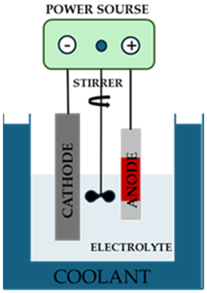
2.1.1. Treatment: Micro-Arc Oxidation

The micro-arc oxidation (MAO) treatment was conducted in a silicate-based solution (0.04 M) and sodium hydroxide (0.05 M) using the cell schematized in Figure 1 [35]. The magnesium specimens, used as an anode, with an exposed area of 1 cm2 and appropriately protected on the rest of the surface with red shielding tape, and a platinum plate used as a cathode were connected to the power source (TDK, Lambda, Milan, Italy). A hanging agitator ensured the continuous mixing of the electrolyte (40 rpm), while the coolant maintained a temperature for the bath lower than 20 ± 2 °C. The anodization was performed in a galvanostatic condition, applying a current density value of 0.030 A/cm2 for 1200 s. At the conclusion of the anodization, the specimens were washed in distilled water and dried in a compressed air flow.

2.1.2. Bio-Inspired Coating

The anodized specimens were dipped for 3 h in the mild stirred bio-inspired solution, composed of 0.2 g of dopamine hydrochloride (C8H11NO2·HCl) in 100 mL of 0.01M Tris (C4H11NO3) buffer solution (pH 8.5), prepared an hour before the treatment to allow the polymerization process [36]. The specimens were then washed under a distilled water flow and dried in a jet of cold air. Although the coating deposited was very thin, about ten nm, brown coloration was observed on the specimens’ surface.

2.1.3. Polylactic Acid Film

The last layer covering the specimens was made of a biodegradable polymer, polylactic acid, applied using a green technology, i.e., hot pressing, which avoids the use of the strong chemical solvents otherwise necessary to dissolve the PLA [28]. Briefly, a PLA film, placed on the treated samples (via anodization and/or bio-inspired deposition), was pressed onto them by applying 2 bar for 300 s at a temperature of 170 °C. The optimal process conditions were considered to be those that produced specimens whose manual disassembly allowed the removal of only the excess PLA, which was not in contact with the metal substrate.
The final structure of the sample, including the coating consisting of an inner layer of anodic oxide, an intermediate layer of polydopamine, and an outer PLA film, is visualized in Figure 2.
In particular, six types of samples were prepared, hereinafter indicated as follows: (1) Mg SS (Mg alloy untreated); (2) Mg-PDA (Mg alloy covered with only a polydopamine layer); (3) Mg-PLA (Mg alloy covered with only a PLA film; (4) Mg-MAO (Mg alloy after the anodization); (5) Mg-MAO-PDA (Mg alloy after anodization and the deposition of polydopamine layer); (6) Mg-MAO-PDA-PLA (Mg alloy after anodization, the deposition of a polydopamine layer, and the application of the PLA film).

2.2. Surface Characterizations

Surface morphological features were captured with a confocal laser scanning microscope (Lext 5100, Olympus Evident, Tokyo, Japan) and a scanning electron microscope (SEM, Mod. FEI QUANTA 200 F, Hillsboro, OR, USA) at an accelerating voltage of 20 kV in a high-vacuum condition, connected with an energy-dispersive X-ray analysis (EDX, Oxford, UK) probe. After the chemical analysis, the specimens were sputtered with an ultrathin conductive layer based on gold alloy. The images were taken at 1000×. The crystallographic structure of the oxide layer was investigated using a Gracing Incidence X-Ray Diffraction analysis (GI-XRD, PANalytical X’Pert PRO, Milan, Italy). The roughness measurements of the anodized specimens were carried out using the confocal laser scanning microscope mentioned above, and some of the most useful roughness parameters were considered, as reported in a previous paper [37]. Three different areas of about 62.5 mm2 were analyzed for each type of sample, and the average value of the roughness parameters was calculated. The hardness of the oxide coating was evaluated with a Vickers micro-hardness test (HX-1000 Remet, Bologna, Italy) from the top view, using a load of 100 g (HV0.1) applied for 15 s. The average value of ten measurements of each specimen was reported.
To study the corrosion characteristics in vitro, potentiodynamic polarization and electrochemical impedance spectroscopy (EIS) analyses were carried out, employing a potentiostat with an integrated frequency response analyzer (Interface 1010E, Gamry, Voghera (PV), Italy). The latter instrument was connected to a classical electrochemical system in which the specimens were used as working electrode; a platinum wire was linked to the counter-electrode, while a saturated calomel electrode (SCE) was used as a reference electrode to measure the working electrode potential. The electrolyte consisted of Hanks’ Balanced Salt solution [38] maintained at body temperature by means of a thermostatic bath. The open circuit potential (OCP) value, observed for ten minutes, was used to polarize the specimens from −100 mV against the OCP until a current density value of 1 mA/cm2 was achieved, with a sweep rate of 0.166 mV/s. If the potentiodynamic polarization curve is a single time-point test that changes the surface specimen, the EIS allows one to study its alteration over time. The EIS spectra were recorded for 7 days via the application of a low-intensity potential signal in an AC regime with respect to the OCP value in the frequency range from 50 × 105 Hz to 2 × 10⁻² Hz. Hanks’ Balanced Salt solution was changed every day. The tests’ reproducibility was ensured by repeating all analyses three times.

3. Results

3.1. Morphological and Chemical Analysis

The images in Figure 3 depict the appearance of the specimens taken before and after the polydopamine deposition and/or anodization. The different coloration is due to the presence of the brown polydopamine layer on the Mg-PDA specimen, and the gray oxide is due to the anodic coating on the Mg-MAO specimen, while the light brown on the Mg-MAO-PDA specimen is due to the polydopamine layer on the porous structure of the oxide coating. The presence of the PLA coating (Figure 3e) is not easily discernible from optical images.
The SEM observations reported in Figure 4 reveal the effect of polydopamine on the magnesium substrate, which tends to degrade due to the pH value of the polydopamine bath (Figure 4b). According to the Pourbaix diagram, the magnesium in contact with an aqueous solution at a pH value of 8.5 produces Mg2+ ions [39]; in other words, it corrodes. In particular, the surface appeared cracked [40], although the grooves generated during the mechanical pretreatment were still evident, suggesting the formation of a very thin but not uniform-thickness polydopamine layer. As previously reported [41], the cracked morphology could be attributed to the dehydration of the polydopamine layer during the drying phase of the treatment. Whereas the anodization involves the well-known pancake-like feature with several pores that have an average diameter of 2.5 ± 0.8 µm (Figure 4f) and random oblong pores having larger diameters, generated via the coalescence of multiple pores. When polydopamine covered the oxide anodic coating, a widening of the porosity was observed, as the mussel-inspired layer could internally erode the oxide pores. An analogous result was found by Chu et al. [42] when the anodic oxide coating of AZ31B magnesium alloy wires was sealed in a ZrO2 sol system, probably due to shrinkage during the drying of a zirconia sol–gel coating. The application of PLA film covers the porous surface, slightly revealing the pattern of the polymeric coating according to an ordered scheme (Figure 4e), as will be better revealed later (see Figure 11).
The cross-sectional view of the Mg-MAO specimen in Figure 5 shows a thickness of about 13.3 ± 2.2 µm and a structure consisting of a very thin barrier layer covered by an outer porous layer with large pores due to the development of gas during the anodization in this region, which has been widely reported in the literature.
The EDX analysis performed on the Mg specimen (Figure 6a) shows the presence of oxygen, in addition to the main component of the alloy, zinc and aluminum, due to the high reactivity of magnesium with the oxygen, which involves the easy growth of oxide on its surface. The chloride peak could be due to the residual acid used during the pretreatment to etch the surface. Although the XPS analysis is the best characterization technique, especially for nanometric coatings, to evaluate the presence of polydopamine, the EDX analysis allowed the discovery of additional carbon and nitrogen peaks on the Mg-PDA sample (Figure 6b), which were related to the dopamine aromatic chain and the amine group attached to it, respectively [43]. On the anodized sample, in addition to the elements constituting the alloy, aluminum and zinc, oxygen was also detected due to the formation of the anodic oxide coating, contaminated by the silicon and sodium elements present in the electrolytic solution and dragged inside via the micro-discharge channels created during the MAO treatment (Figure 6c). The specimen covered with the polydopamine layer on the oxide coating exhibits all the previously shown peaks (Figure 6d). The presence of the PLA film revealed, as expected, a marked peak of carbon and oxygen (Figure 6e).
In Figure 7, the SEM cross-section view of the specimen after the micro-arc oxidation treatment, the polydopamine deposition, and the hot-pressed PLA is depicted. The polydopamine layer, being very thin, was difficult to detect. A lack of very defined interfaces suggests good adhesion between the layers. However, it was possible to see that hot pressing reduced the thickness of the PLA to about 25 ± 2 µm.

3.2. Crystallographic Analysis

In Figure 8, the XRD spectra of the only anodized samples compared to the untreated samples are reported to investigate the crystallographic structure of the oxide layer. Via the analysis of the characteristic peaks, peaks corresponding to the MgO and Mg2SiO4 phases are present in the anodized sample. This confirms the theoretical finding that, as a result of the continuous melting and re-solidification of the oxide during the complex PEO process, there is an enrichment of the composition of the coating, which will eventually also contain the elements present in the electrolyte [44]. In addition, Mg-associated peaks representing the metal substrate were observed, suggesting the penetration of the X-ray in the bulk of the substrate, although a gracing incidence analysis was carried out. The β-phase (Mg17Al12) composed the substrate, but as the Al concentration in the AZ31 alloy is low, the amount is probably too low to be detected through the XRD measurements [45]. Owing to the amorphous nature of PDA and PLA, new peaks were not possible to identify in the XRD patterns [46]. Given the thickness of the PLA film, it is reasonable to expect a lower peak intensity of magnesium for the coated sample, as was already observed for the anodized-only one. The Joint Committee on Powder Diffraction Standards (JCPDS) schedules used to identify the phases are Nos. 35-0821 for Mg, Nos. 30-0794 for MgO, and Nos. 35-0821 for Mg2SiO4.

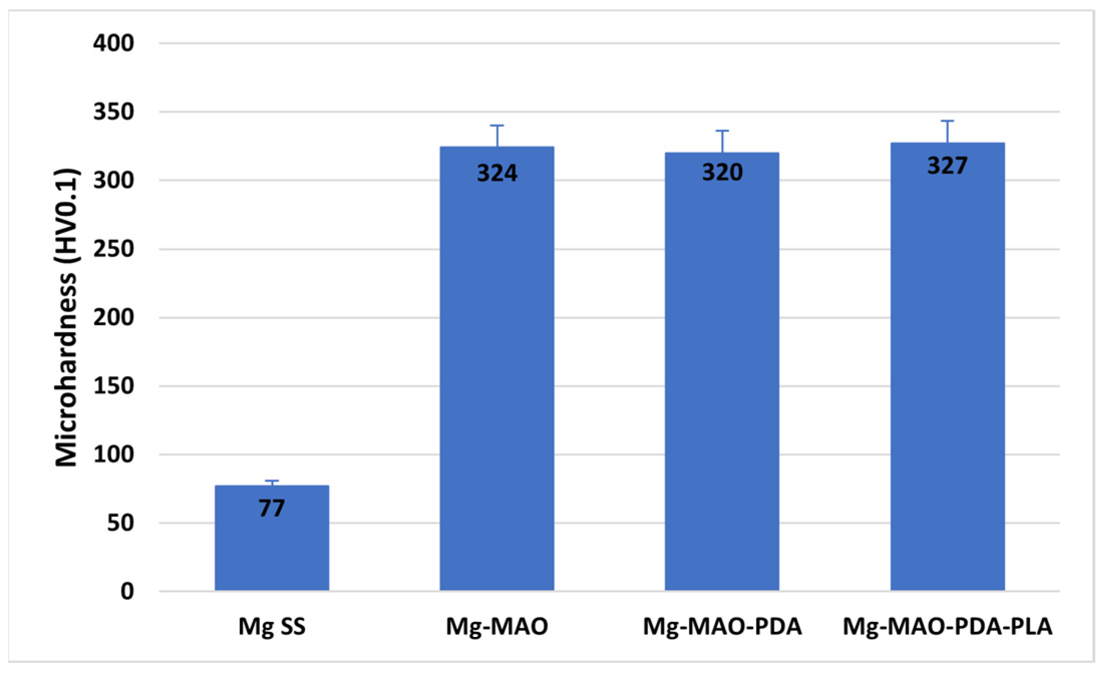
3.3. Micro-Hardness Test

The ceramic-like characteristic of the oxide layer should provide good hardness properties, depending on the phase structure and compactness. The oxide coating, given its ceramic nature, shows higher values of this parameter compared to the magnesium substrate, as reported in Figure 9. Specifically, for the magnesium substrate, a value of about 77 ± 5 HV was recorded, whereas the anodic coating presents a micro-hardness of about 324 ± 20 HV, higher than the values reported in literature [47]. The contribution of organic coatings, polydopamine and PLA, does not provide any substantial change in the hardness of the sample.

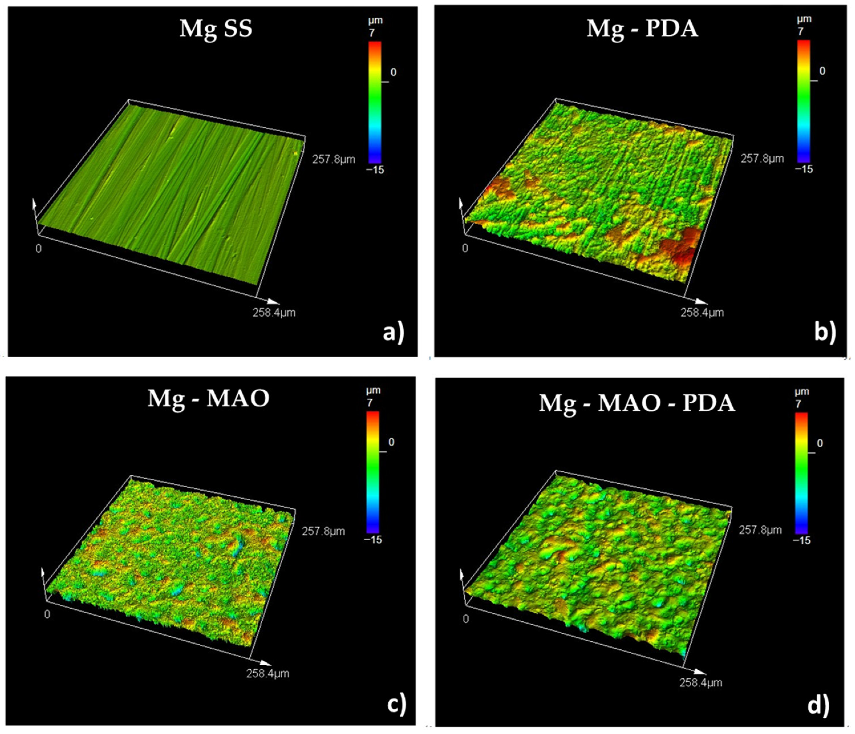
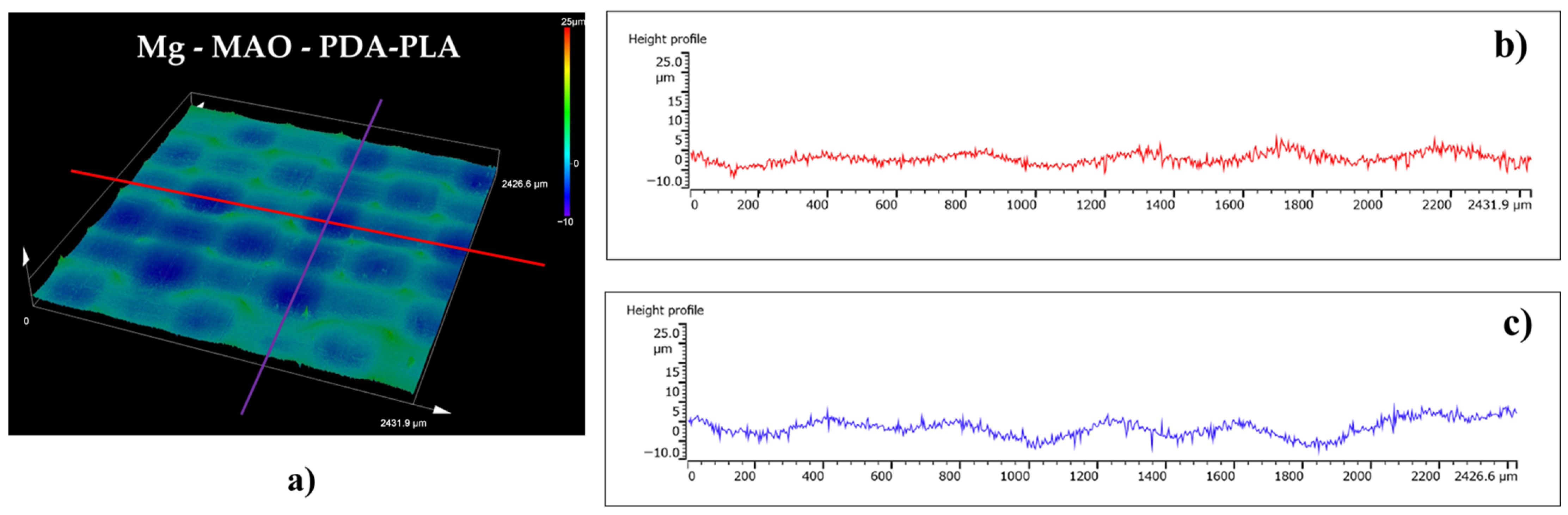
3.4. Roughness Measurements

The surface roughness parameters values obtained by performing the measurements by means of the laser confocal scanning microscope are listed in Table 1.
From the results, it is interesting to note the effect of the PDA deposition when it is applied on both the magnesium substrate and the oxide coating. In the first case (Mg-PDA specimen), as expected, a change of the Sa parameter was recorded, from 0.3 to 1.3 µm. In addition, an erosion effect can be detected when observing the higher values for Sp and Sv, suggesting higher peaks and lower valleys. As a result, the resulting developed area, Sdr, increases from 2.1% to about 40%. The only anodization treatment (Mg-MAO) further amplifies the distance between the peaks and the valley, extending the developed area of about 300% (Sdr), and it produces a morphology characterized by sharp peaks and the prominence of valleys, as shown in the Sku and Ssk values, respectively. The deposition of the mussel-inspired coating (polidopamina layer) on the anodized specimen, on the other hand, reduces the peak-to-valley distance by filling the porosity, and it significantly smooths the surface, as evidenced by the reduction in the Sdq value of 1%, particularly changing the shape of the peaks, as attested by the reduced value of Sku.
Three-dimensional roughness graphs are displayed in Figure 10. The magnesium substrate has a smooth surface with evident grooves due to mechanical pretreatment. The erosive effect of the polydopamine layer can be detected on Mg-PDA samples whose surface appears rough. The anodizing treatment results in a very porous surface, with clear sharp peaks and deep valleys. The polydopamine layer on the anodic coating presents enlarged pores, confirming the SEM observations, smoothing the peaks, and filling the valleys, as evidenced by the lack of blue zones (see Figure 10 Mg-MAO-PDA sample). A similar effect was observed by Li et al. [48] when covering the anodic oxide coating functionalizing clinochrysotile-like magnesium silicate nanotubes (MSNTs) with a corrosion inhibitor.
Although the importance of surface topography for cell adhesion, migration, differentiation, and proliferation processes is widely discussed in the literature [49], and it is established that cells are able to recognize the chemical [50] and topography of the substrate used as contact guidance for their development process, the topic remains very complex since a surface can be characterized by different levels of roughness: macro-, micro-, submicron-, and/or nano. At the same time, it could present pits, grooves, fibers, or pores with a chaotic or ordinate texture. Several papers [51,52,53,54,55] have investigated the influence of an isotropic or anisotropic pattern on cells’ behavior, revealing a better response in the former case and also defining the beneficial size and shape of the micro-chambers composing the pattern when considering the cells’ size (about 10–20 µm). Nikkahn et al. [56] studied the influence of two kinds of 3D isotropic patterns of a silicon substrate, designed with star-shaped or circular micro-chambers of about 150 µm in width and 50 µm in depth, on the adhesion of human fibroblast cells and human breast cancer cells (MDA-MB-231), demonstrating the different influence of the micro-chamber’s shape on the adhesion mechanism between healthy and diseased cells. Altomare et al. [57] investigated several varieties of grooves depths (0.5–5 µm) and widths (5–100 µm) to improve myoblast cells’ behavior on a PLA/trimethylene carbonate copolymer film. The authors, although they obtained the best finding from deeper and narrower grooves, highlighted the importance of also studying the behavior for a long time period due to the improvement in cellular development after the first days. Different techniques are listed in the literature to obtain desiderata from 3D micro-patterns [49]. In this work, the hot-pressing technique used to apply the PLA film allowed a specific surface pattern to be imprinted and used as contact guidance, with the opportunity of possibly also choosing the valleys’ shape and size to stimulate the regenerative processes of the host tissue. The 3D graph of the Mg-MAO-PDA-PLA sample displayed in Figure 11a shows an isotropic pattern, characterized by circular micro-chambers, of the PLA film. This pattern was not revealed via SEM observations due to the high magnification used.
To verify the shape of the valleys, profile measurements were taken along perpendicular directions, a representation of which is shown in Figure 11b,c. It is possible to note the curved side walls of the valleys, characterized by a width of approximately 400 µm and a depth of approximately 5 µm.

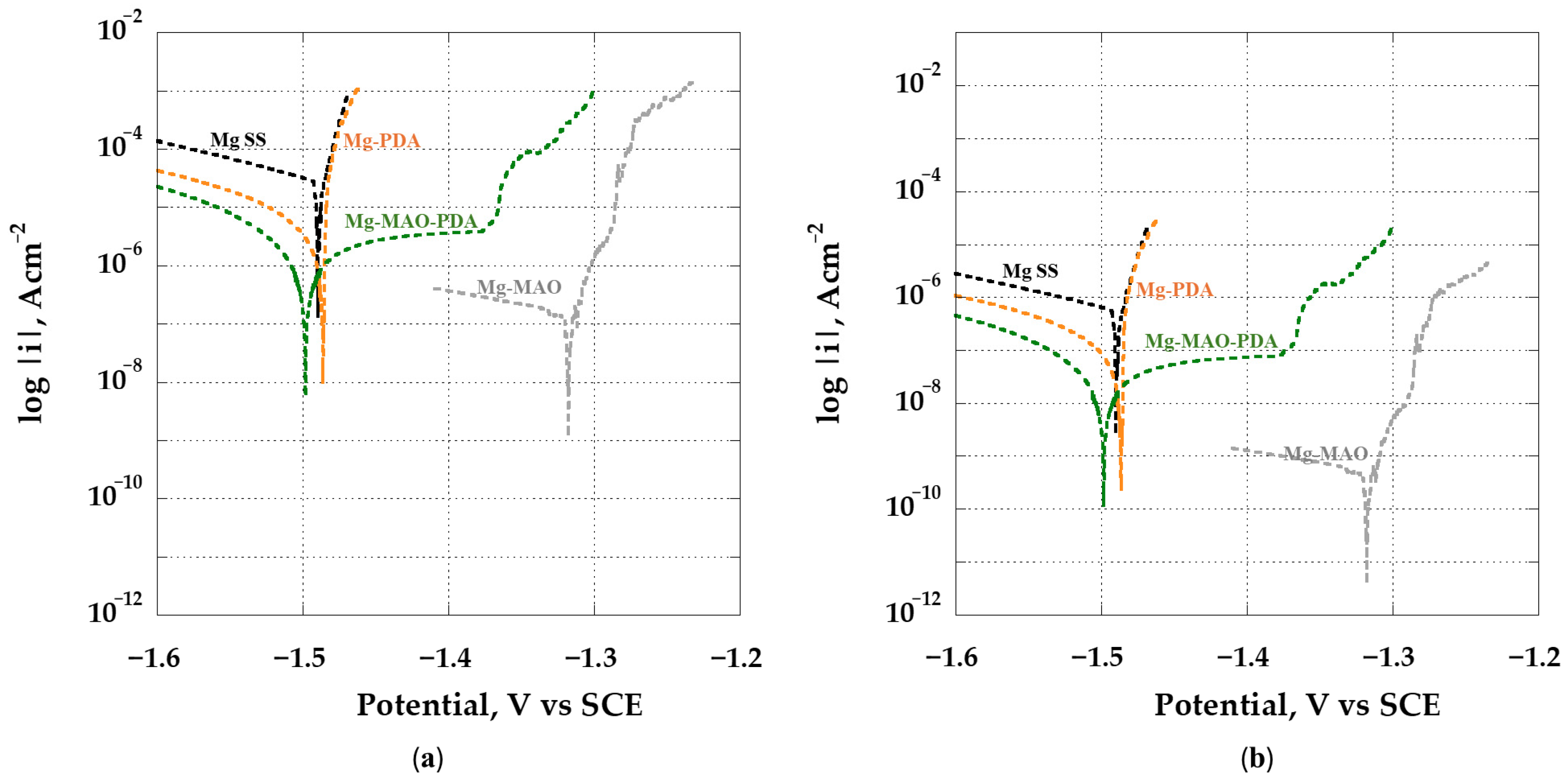
3.5. Electrochemical In Vitro Characterization

It is well known that, when magnesium and its alloys are in contact with an aqueous solution with a pH value lower than 9, the degradation process involves the following partial reactions [58]:
Mg → Mg2+ + 2e (anodic reaction)
2 H2O + 2e → H2 + 2 (OH) (cathodic reaction)
Mg2+ + 2 (OH) → Mg(OH)2 (product formation)
The magnesium hydroxide and magnesium oxide, formed as by-products, will deposit on the surface of the metallic substrate, forming a protective film whose stability is affected by the local pH value, which changes due to the cathodic reaction (2). In addition, the presence of chloride ions in the solution could transform the protective layer MgO/Mg(OH)2 into soluble MgCl2 [59]. An important aspect to consider regarding the corrosion of magnesium, in contrast to other metals such as iron or aluminum, is the so-called “negative difference effect” (NDE) that it shows when it is anodically polarized [60]. This means that, when the anodic overpotential is increased, the cathodic current density of hydrogen rises instead of decreasing. So, the oxidation results in an increasing production of hydrogen gas, causing the breakdown of the protective film and a fast increase in the anodic current. However, by controlling Mg alloy corrosion kinetics, the development of hydrogen gas can be controlled. It may be pursued by allowing the process of degradation of the metal substrate in the body environment, the so-called biodegradation process, to occur at a rate comparable to the rate of healing of living tissue (i.e., bone growth) so that the amount of hydrogen produced can be such that the harmful effects it produces are avoided; at the same time, the daily amount of magnesium ions released in the body does not exceed an amount of 330–420 mg/day [61].
Being a valve metal, magnesium and its alloys could generally degrade according to the pitting corrosion mechanism, a kind of mechanism related to the local rupture of the protective layer and the formation of small pits that trigger the degradation process. For magnesium alloys, the presence of second phases or intermetallic compounds also involves galvanic corrosion due to different electrochemical potential between the α-Mg matrix and second phase or intermetallic phases, such as β (Mg17Al12), composing the Mg-Al series alloys. The secondary β-phases are cathodic to the α-Mg matrix [58] and have good passive behavior over a broad range of pH values. However, their contribution to the corrosion process depends upon their amount, size, and distribution. When the grain size of a magnesium alloy is small and the volume fraction of the β-phase is high, the distribution of the β-phase on the α-Mg matrix is continuous, providing corrosion protection through a barrier layer effect. On the other hand, if the grain size is larger and the β- phases cannot cover the α-phase completely, galvanic corrosion results with the α-phase acting as an anode and undergoing corrosion [62]. The corrosion product, Mg(OH)2, precipitates over the α-Mg matrix, and this surface film is only partially selective, as the continuity of the film is interrupted by the presence of the secondary phase.
The corrosion of magnesium and its alloys in Hanks’ Balanced Salt solution has been widely investigated [63,64,65,66]. However, to the best of the authors’ knowledge, few papers have discussed the corrosion of the AZ31 magnesium alloy in this kind of solution, simulating the body’s living environment. Bukovinova and Hadzima [67] investigated the corrosion mechanisms of two different processing technologies, casting and extrusion, used to produce samples of the AZ31 in Hanks’ Balanced Salt solution for about 500 h through electrochemical impedance spectroscopy analysis. They found that the technologies influenced the morphologies and degradation rates; in fact, in the case of cast alloy, corrosion proceeds more in depth in the sites with the initial surface damage, while for extruded alloys, corrosion proceeds more in width with an increasing exposure time. A finer microstructure of the extruded alloys leads to a more uniform corrosion process in a physiological solution compared to the non-uniform degradation process developed on the cast alloy, characterized by a coarse microstructure. Xin et al. [68] deeply investigated the corrosion mechanism of AZ91 in Hanks’ Balanced Salt solution and, among other things, highlighted the influence of the secondary phase, which, although forming galvanic couples, blocks the spreading of corrosion along the α-Mg matrix when they form a continuous distribution around it. Magnesium and calcium phosphate precipitates were found in addition to the expected corrosion products. In particular, they claimed that both the increase in the pH, due to the reaction (2), and the high presence of Mg ions in the physiological solution suppresses the formation of calcium phosphate in the typical ratio of the hydroxyapatite but stimulate the precipitation of the magnesium phosphate.
In this research, to study corrosion behavior in terms of the corrosion current density and corrosion mechanism, potentiodynamic polarization tests and electrochemical impedance spectroscopy analyses, respectively, were performed in Hanks’ Balanced Salt solution at 37 °C. From potentiodynamic polarization curves, it is possible to define good corrosion resistance when the curve records high corrosion potential, Ecorr, and a low current density, icorr. The potentiodynamic polarization scans obtained from analyzing the samples are displayed in Figure 12. In Figure 12a, the Mg SS curve shows the highest current density value and a low corrosion potential, Ecorr, of about −1.48 V vs. SCE, also reported in the literature [69]. The deposition of the polydopamine layer, while recording a near corrosion potential value to the Mg SS and presenting a cracked surface, reduces the corrosion rate by about one order of magnitude [70]. Instead, when the micro-arc oxidation treatment is performed, a decrease of two orders of magnitude in the current density is possible to detect (Mg-MAO), along with an increase in the corrosion potential (about −1.32 V vs. SCE), indicating that the physical barrier of the oxide coating can be an effective pathway for enhancing the corrosion properties. The lack of a passivity range should not be surprising due to the porosity characterizing the coating, as recorded for aluminum alloys [71,72]. The dipping in the polydopamine bath after the anodizing (Mg-MAO-PDA) would seem to compromise the beneficial effect of oxidation in terms of Ecorr since this parameter was reduced compared to that of the Mg-MAO specimen, probably due to a catalytic effect explained in the following. However, the current density is the term that must be considered when evaluating corrosion resistance properties. Looking at the current density, we find that the Mg-MAO-PDA sample presented a good reduction in the corrosion current density compared to the untreated and only polydopamine-covered samples, as shown by the shift in its curve towards lower current densities. In addition, it presented a behavior like that shown in the pseudo-passivity condition, as reported, for example, by Jothi et al. [73]. In this case, it was due to the polydopamine layer, which, by penetrating pores, simultaneously enlarges and seals them, as highlighted by roughness measurements, conferring good corrosion resistance.
All the above considerations regarding the corrosion current density can be applied if the geometrical area is considered (Figure 12a). However, from roughness measurements, it is possible to consider the real extension of the samples’ area (Figure 12b), which has never been investigated in the literature. In particular, by considering the Sdr parameter (see Table 1), which represents the percentage extension of the area, and knowing the geometrical area on which the roughness measurement was performed, the real area was estimated through a simple proportion. This allows an impressive reduction in the corrosion rate evident as the translation of the curves towards lower current densities (Figure 12b), especially for the anodized samples, i.e., Mg-MAO and Mg-MAO-PDA.
The lack of an activation mechanism and the quick achievement of a trans-passivity condition do not allow for the calculation of the corrosion rate using the Tafel approach specified in the standards of ASTM G102-89 (Reapproved 2015) [74]. In these cases, an extrapolation of the above-mentioned approach is possible for determining the corrosion current density, identified as the intersection point between the tangent to the cathodic branch and the corrosion potential, Ecorr. The Mg SS sample shows a corrosion current density of 2.65 ± 0.3 × 10⁻⁵ A cm−2 [75], a value similar to that obtained considering the geometrical area. As expected, the anodized sample Mg-MAO records a very low corrosion current density of 5.99 ± 0.8 × 10⁻¹⁰ A cm−2. The only polydopamine layer (Mg-PDA) improves the corrosion current density compared to the untreated sample, 1.94 ± 0.3 × 10⁻⁷ A cm−2, due to the formation of a rougher surface than that of the untreated sample. The Mg-MAO-PDA specimen exhibits a pseudo-passive range, confirming the sealing of the pores already shown via roughness measurements. Thus, in these cases, the pseudo-passivity current density is the kinetic better data to consider, which is equal to 7.35 ± 0.4 × 10⁻⁸ A cm−2, instead of the corrosion current density value. Its higher value than that of Mg-MAO could be due to some effect explained in the EIS analysis, which confirmed this behavior. The corrosion parameters evaluated from potentiodynamic polarization curves are summarizedin Table 2.
The EIS results obtained from all samples allowed to derive interesting considerations about the role played by the various constituents of the three-layer coating studied. In Figure 13, the Bode plots spectra of the specimens obtained at the beginning of the immersion in Hanks’ Balanced Salt solution at 37 °C are shown.
The poor corrosion resistance in the presence of chloride ions of the magnesium alloy is confirmed by the response offered via the Mg SS sample, which presents an impedance modulus at a low frequency range (0.02–1 Hz) of about 102 Ω cm2. Two constant times in the phase plot, one at medium frequencies and another at low ones, indicate two electrochemical processes [76], the charge transfer, and the absorption of intermediate species, which are also confirmed through the Nyquist plot magnified in Figure 14b, in which a capacitive arc and a folliwing inductive loop are shown [62]. Coating the magnesium substrate with a polydopamine (Mg-PDA) layer shows a slight improvement compared to the unmodified one. The impedance value at the lowest frequencies is one order of magnitude higher, equal to about 103 Ω cm2 [77], while the phase angle plot showed two peaks, one apparent at medium frequencies and another only alluded to in the low ones, but the Nyquist plot highlighted both and also revealed, in this case, an inductive loop. The protective effect offered via the anodization treatment (Mg-MAO specimen) can be clearly highlighted in the Bode plot, where the impedance modulus increases at high frequencies of two orders of magnitude and about four orders of magnitude at low frequencies (106 Ω cm2) compared to the unmodified sample. The improved electrochemical response was also revealed through the capacitance behavior recorded in the phase diagram, which, in the high and medium frequency ranges, shows a value of 90°. Compared to the previous samples, a different curve was recorded in the Nyquist plot, characterized by two enlarged capacitive loops, which are ascribable to the structure of the oxide coating, composed of an inner compact barrier layer with higher protective properties than the outer thick, porous layer. However, the behavior exhibited by Mg-MAO-PDA specimen confirms the potentiodynamic polarization results by showing a reduction in the impedance modulus by more than two orders of magnitude throughout the frequency range when compared with the anodized sample. This behavior can be justified by considering that, during the formation of the polydopamine layer on the anodized coating, a degradation process is triggered. The porosity of the oxide layer could have two effects: the first is determined by the increase in the specimen area and the second by the fact that the pores, due to their size, may behave as occluded cells and thus result in autocatalytic corrosion phenomena. This could be the reason for the reduced corrosion potential recorded in the potentiodynamic polarization test. The Nyquist plot showed an enlarged capacitive arc in the high-frequency range. However, the capacitive arc in the low-frequency range is nearly invisible, and the inductive loop found on the Mg-PDA sample became almost invisible.
When the film of polylactic acid was applied on the polydopamine layer or on the anodic oxide coating, it offered the expected barrier protection. From the Bode plots, displayed in Figure 13, it was possible to check that the Mg-MAO-PLA and Mg-PDA-PLA showed very similar values for the impedance modulus of about 109 Ω cm2, with a capacitive behavior until a value of frequency of 1 Hz, as revealed by −90° of the phase plot. At the lowest frequencies, a resistive behavior was recorded, with a reduction in the angle phase to a 0 value. On the other hand, the Nyquist diagrams (Figure 15) highlight the different electrochemical mechanisms when the PLA covered the samples. The Mg-MAO-PLA revealed a capacitive arc, while the Mg-PDA-PLA sample presented an enlarged but depressed capacitive arc, as if subtending two arcs, and an inductive loop at the lowest frequencies, as alluded to in the same sample without the PLA film. These behaviors suggest an easy penetration of the electrolyte into the PLA film, which is also due to the very low crystallinity of the latter when it is hot-pressed into the sample, as reported by Liu et al. [78]. However, the high impedance modulus values recorded suggest an “electrode block” function of the PLA. The best electrochemical response was conferred when the polydopamine layer was used as an intermediate layer (Mg-MAO-PDA-PLA sample) since the impedance modulus reached a value of 1010 Ω cm2, exhibiting a capacitive behavior until the low frequencies. The different behavior is highlighted in the Nyquist plot, in which a very large capacitive arc was displayed. It is probably due to the synergistic action between the porous and thick oxide layer, with its high corrosion resistance, and the polydopamine coating, which filled the pores and improved the adhesion between the oxide and the thick PLA film to such a level that the oxide/PLA interface could barely be distinguished, as shown in Figure 7 above, in contrast to the findings of Alabbasi et al. [79].
The EIS test was carried out for a prolonged period compared to the previous investigations [80,81], i.e., until 168 h of immersion in the test solution. The spectra are depicted in Figure 16.
An increase of approximately one order of magnitude (1 × 10³ Ω cm2) in the impedance modulus values at the lowest frequency of the unmodified specimen (Mg SS) confirmed the presence of a “protective” layer on the surface through the continuous formation and dissolution processes. This latter, attributable to a Mg(OH)2 layer [82], appears as craters filled with corrosion products in Figure 18, and its presence is highlighted as an inductive loop in the Nyquist plot in Figure 17. During the long immersion in the solution, these deposits become thicker, improving the magnesium’s corrosion properties compared to the beginning of the immersion test.
Although the impedance modulus of Mg-PDA seemed not to change after 168 h, its surface image in Figure 18 shows craters apparently covered by corrosion products attributable to magnesium and calcium phosphate. The anodized specimen, Mg-MAO, after long immersion in the solution, presented a significant variation in the impedance modulus, which reduced its value by two orders of magnitude at the lowest frequencies. However, its surface appears slightly altered with the formation of small white compounds, probably made of phosphate and calcium, as investigated by Seyfoori et al. [83]. The Nyquist plot confirmed the reduction in the protective properties by again showing two capacitive loops with reduced diameters. Exceptionally, the Mg-MAO-PDA sample seemed to present insignificant changes in the impedance modulus during the long observation time but superficially showed some points of degradation, as highlighted by the Nyquist plot with an increasingly lowered arc, as if it subtended two arcs.
The effect procured via the presence of the PLA coating is still clear after 168 h in Hanks’ Balanced Salt solution. Although all samples covered with the PLA film showed a low-frequency impedance value, lower by 4–5 orders of magnitude compared to those recorded at the beginning of the analysis, the values were of about 2–3 × 10⁴ Ω∙cm2, about an order of magnitude greater than the values of the specimens without the PLA film. The impedance modulus values exhibited by these specimens at high frequency remained at the same order of magnitude, but only the presence of the polydopamine layer involved the development of the swelling phenomena, as demonstrated in Figure 18 (Mg-PDA-PLA specimen), due to the cracked surface (see Figure 4b), through which the electrolyte readily penetrated and triggered rapid corrosion. The only anodic oxide layer presents very small and few brown points (Mg-MAO-PLA specimen), suggesting a possible initial degradation process, whereas the contribution of both the anodic coating and the polydopamine layer continued to decelerate the degradation process of the magnesium substrate. The complex corrosion mechanism in the presence of the PLA film was highlighted by the Nyquist plot, in which unavoidable absorption phenomena were observed as inductive loops, suggesting the formation of by-products for the corrosion phenomena, although the surface appearance of the Mg-MAO-PDA-PLA sample seemed to be macroscopically unmodified.

4. Conclusions

Samples of AZ31 magnesium alloy were superficially modified via the deposition of a three-layer coating consisting of an internal layer of anodic oxide obtained through electrolytic plasma oxidation, an intermediate layer based on polydopamine, and a film of polylactic acid applied without the use of solvents.
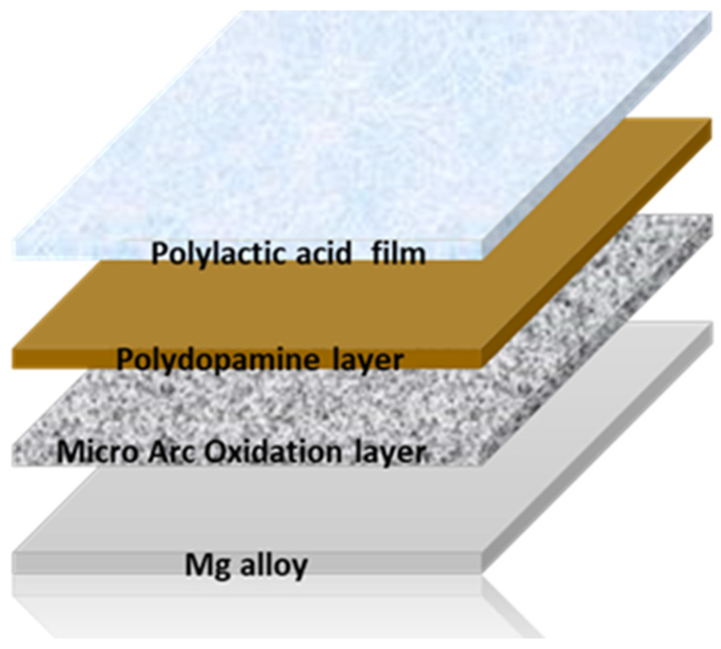
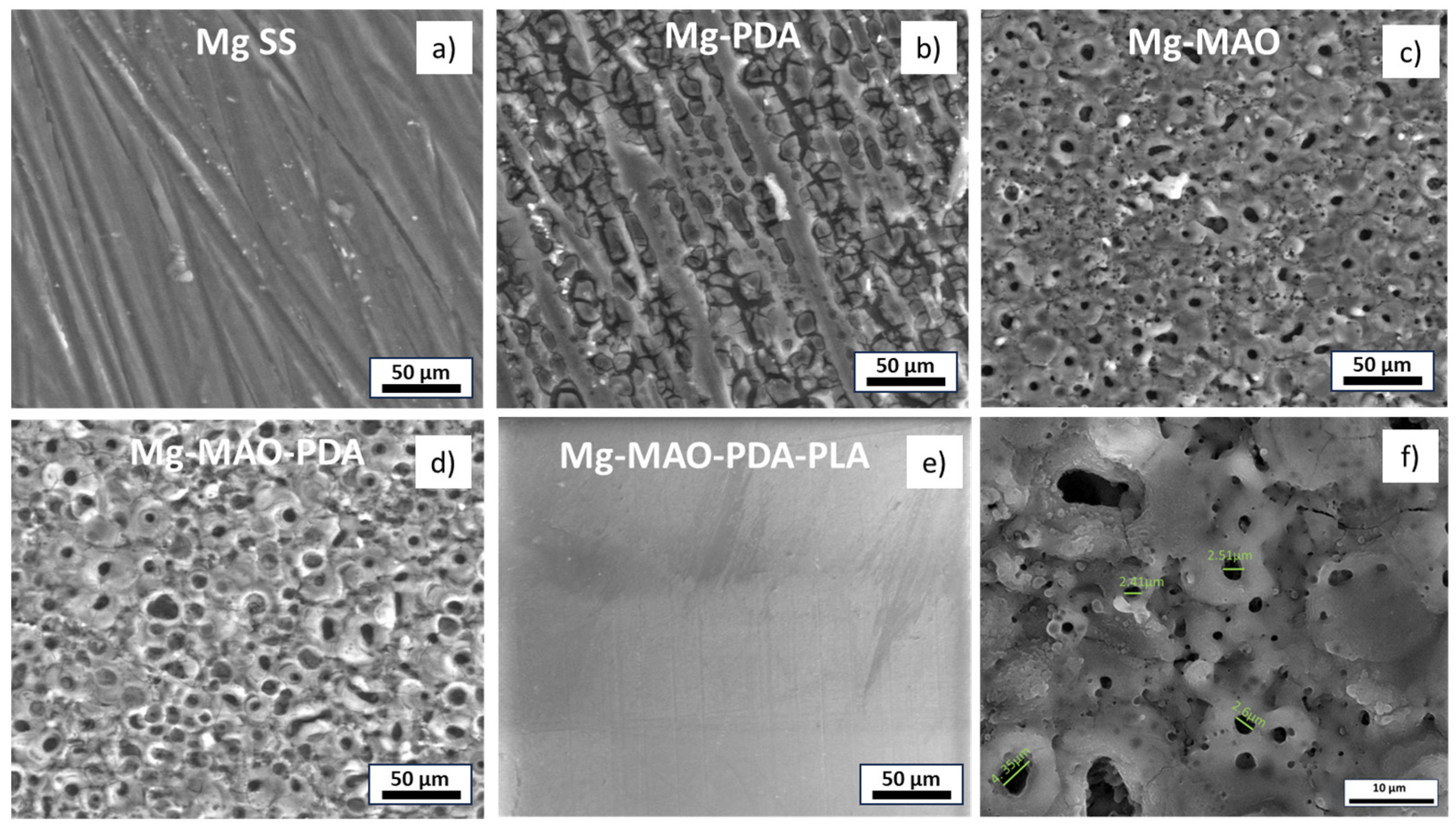
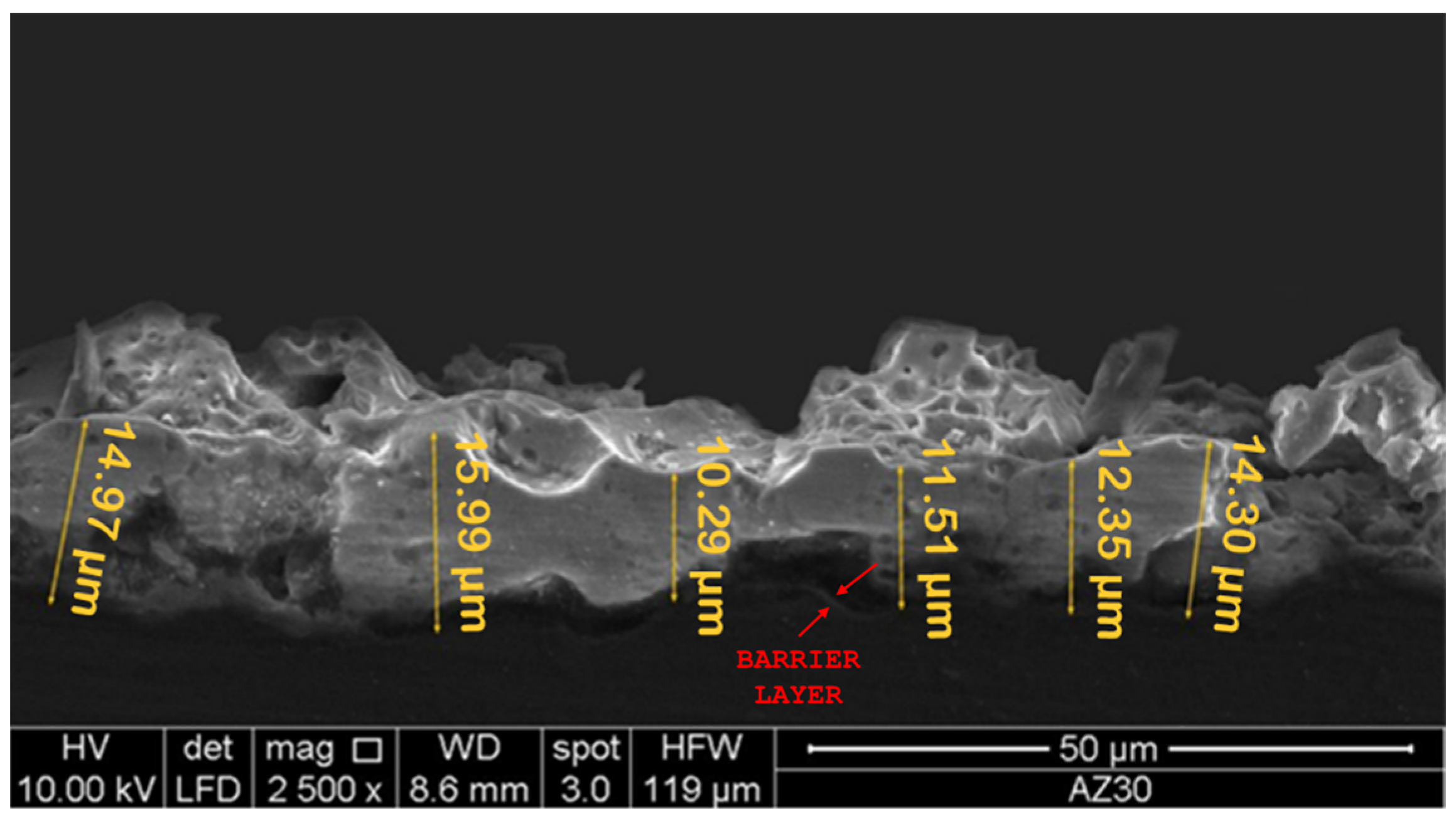
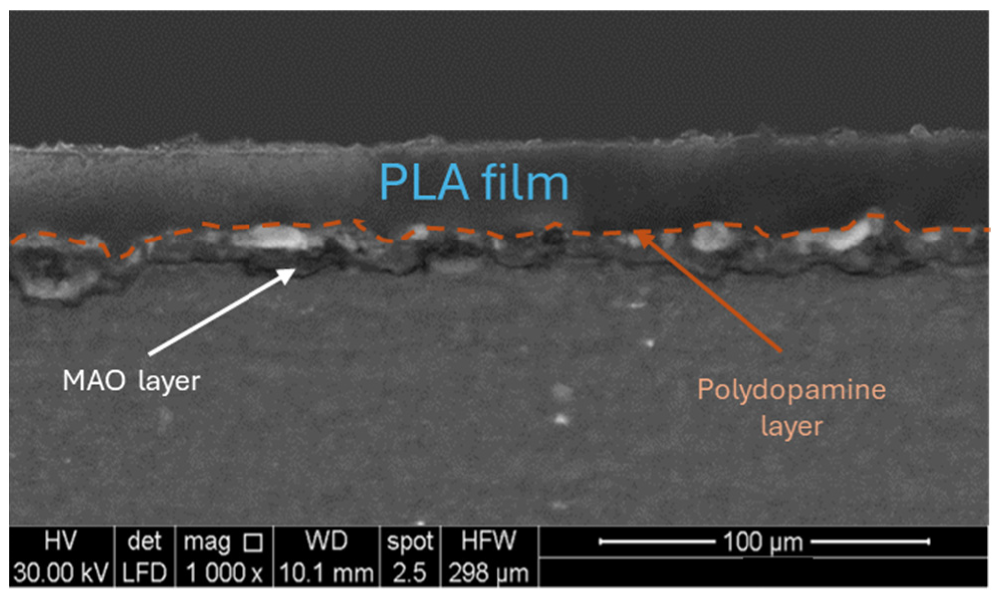
  • The electrochemical treatment involved the classical pancake-like morphology, characterized by many small pores, which were enlarged and filled with the polydopamine layer, whose thickness was nanometric. The thickness of the anodic oxide was of about 13 µm, while the PLA layer showed a thickness of about 25 µm.
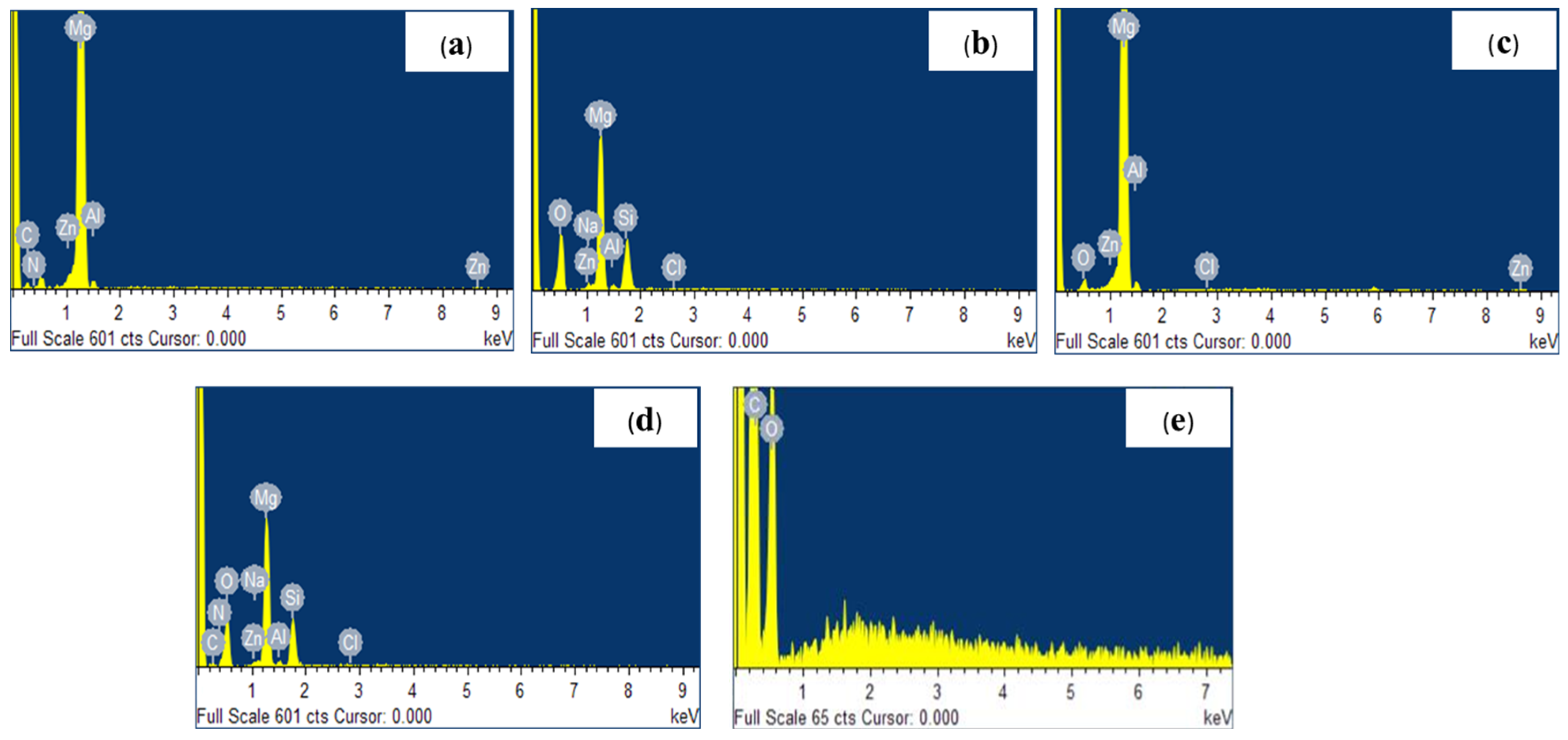
  • The EDX analysis, in addition to the elements composing the substrate, revealed the presence of oxygen, silicon, and sodium after the anodization treatment, as well as the presence of nitrogen and carbon when the polydopamine layer was applied and carbon and oxygen after the deposition of the PLA film.
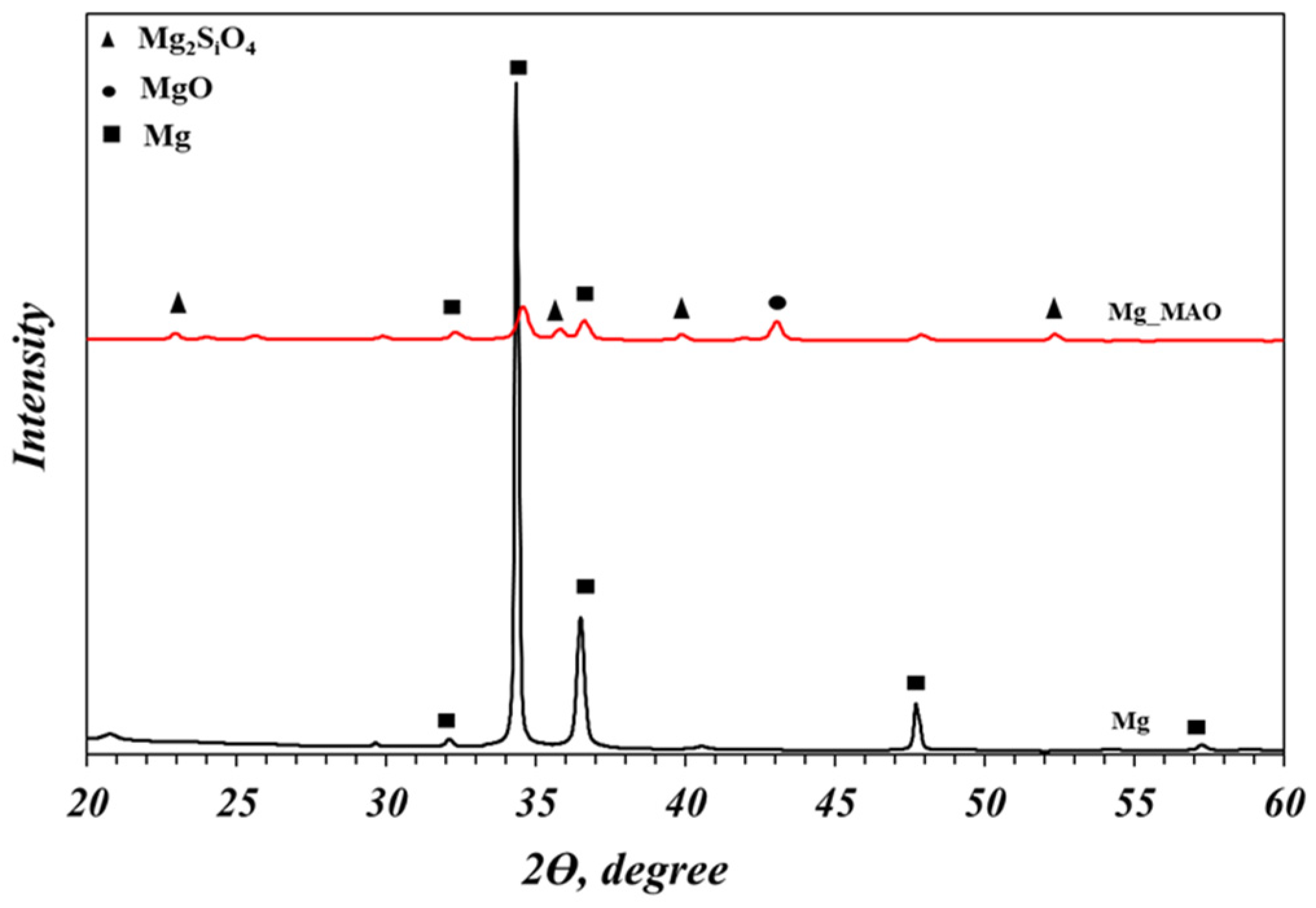
  • The XRD analysis showed the crystallographic structure of the oxide coating, revealing the magnesium oxide and the magnesium silicate as principal compounds.
  • The micro-hardness measurements revealed a higher hardness of the oxide coating compared to the untreated sample. The presence of the polydopamine and the PLA film did not affect the value.
  • The roughness measurement highlighted the great extension of the area after the MAO treatment due to high porosity, as revealed through the Sdr parameters (very high for the Mg-MAO specimen), and the smoothing effect of the polydopamine, as attested to in the Sp and Sv values’ parameters, suggesting the sealing of oxide pores. In addition, the presence of the PLA film gave the surface neat, square patterning, which could improve cellular adhesion.
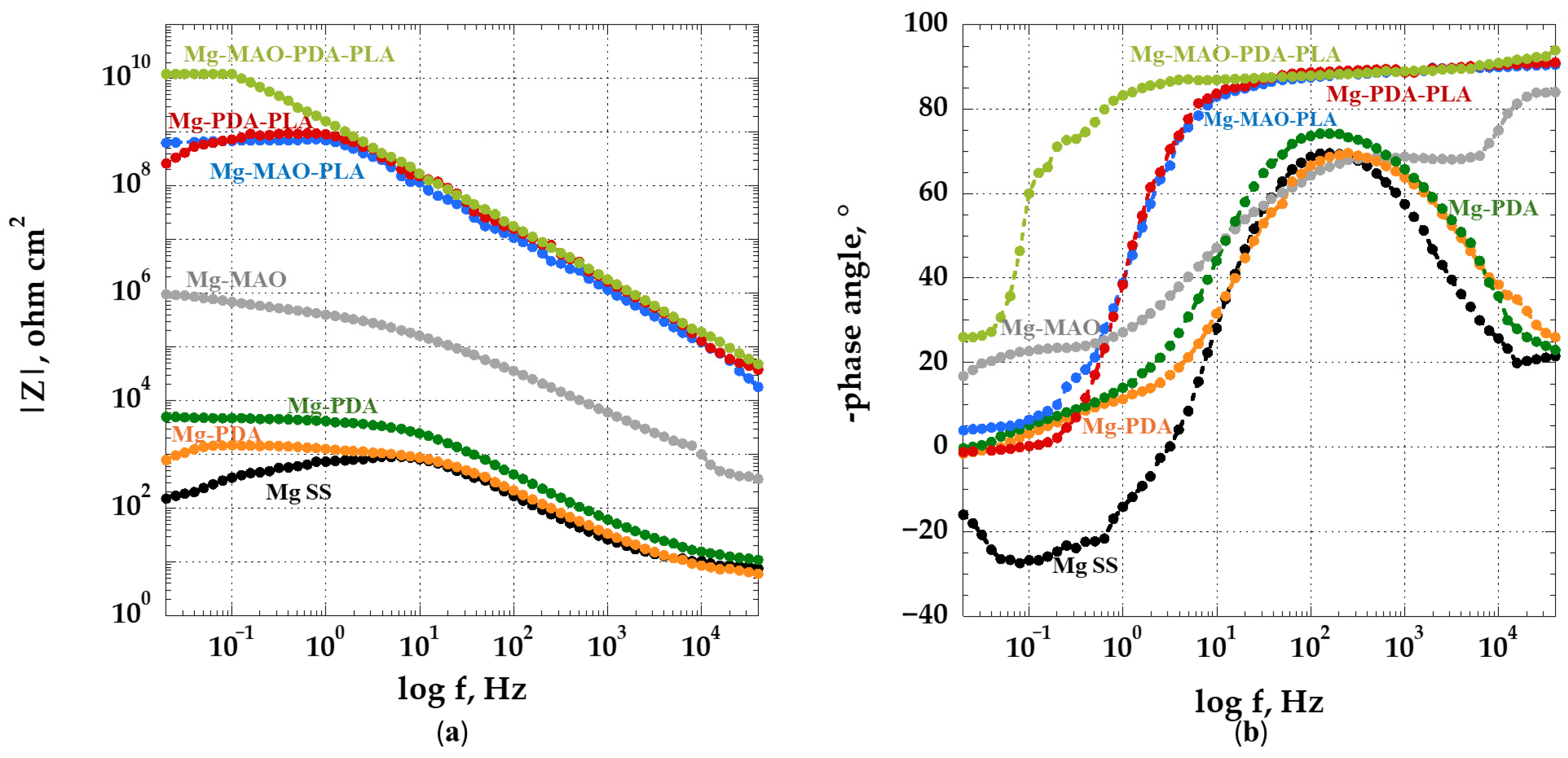
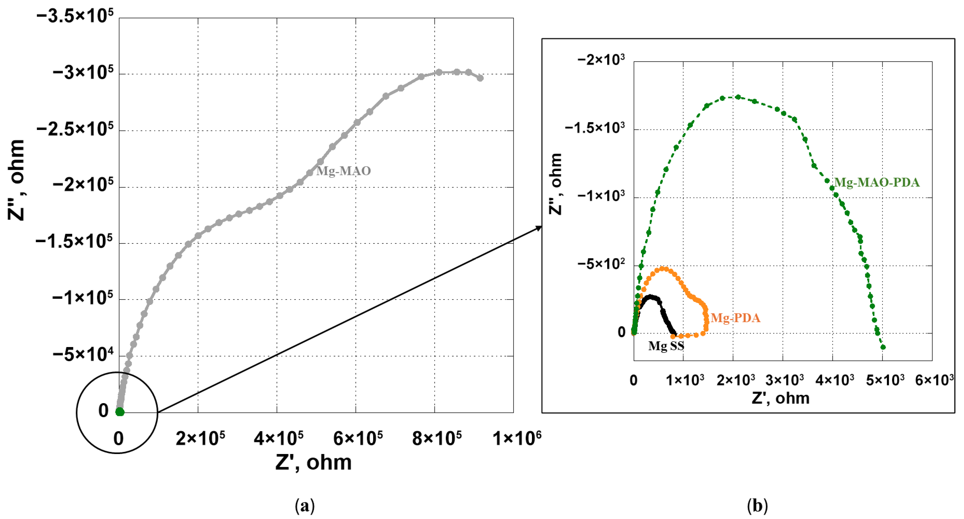
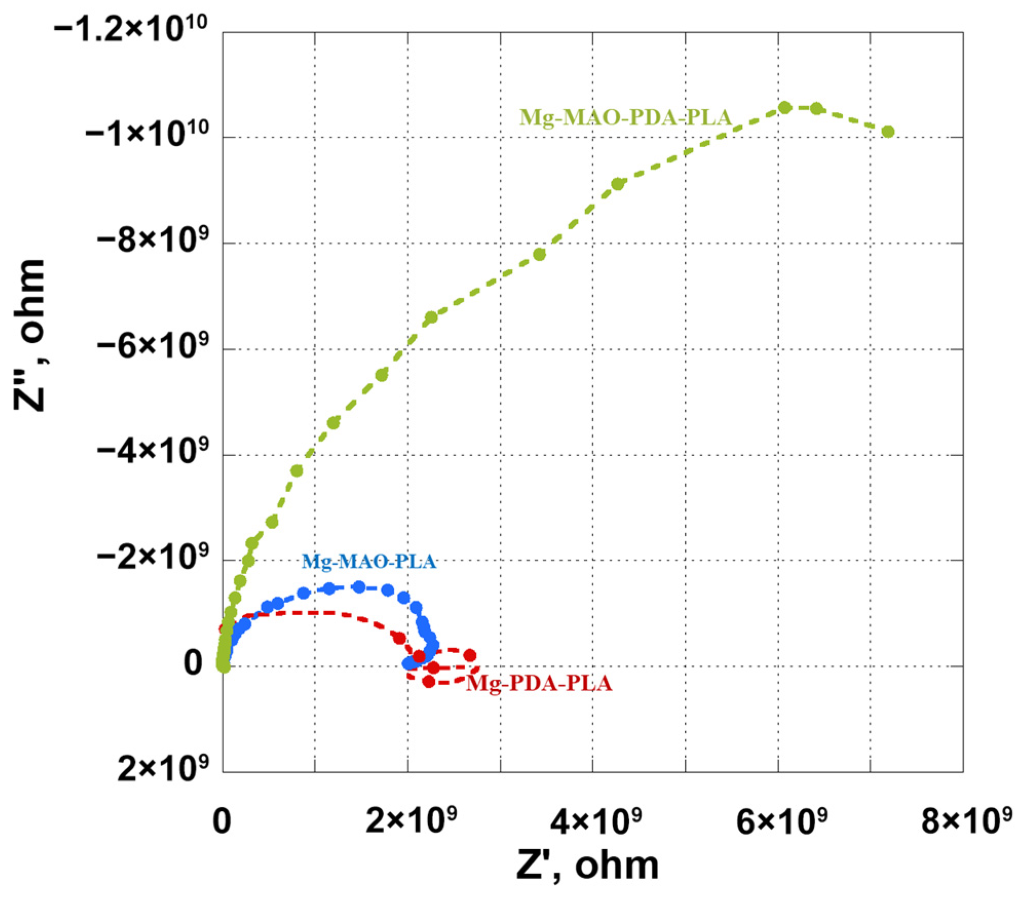
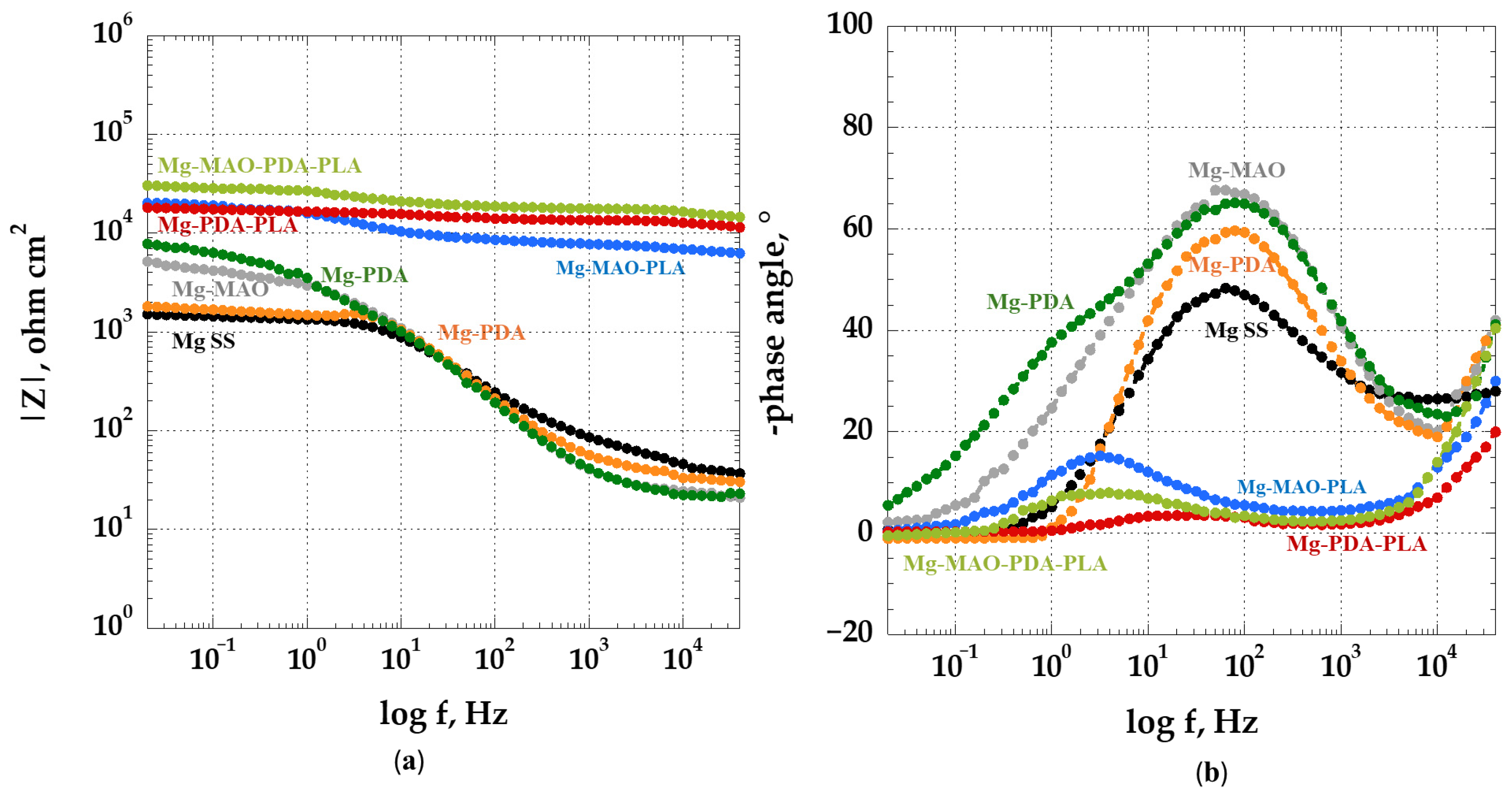
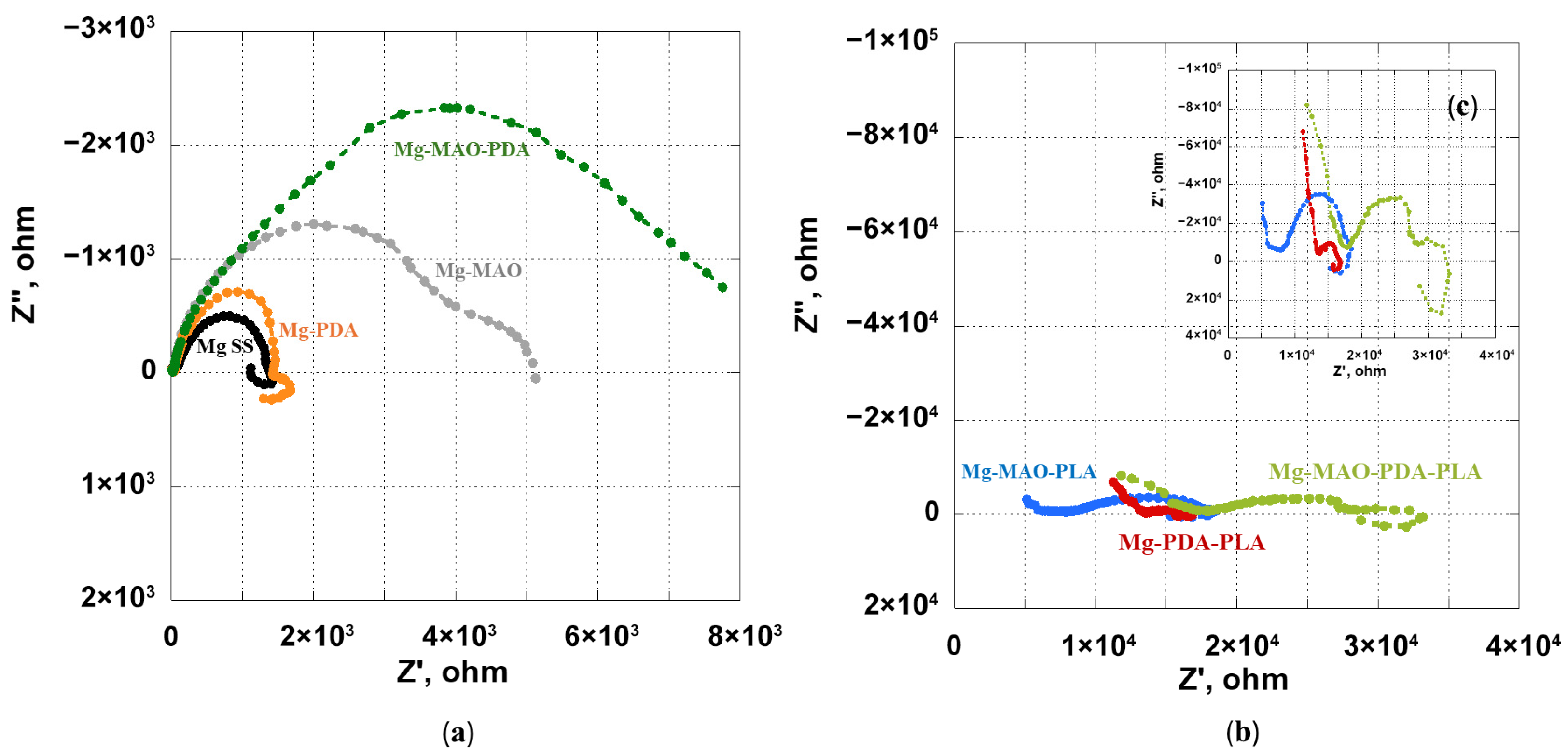
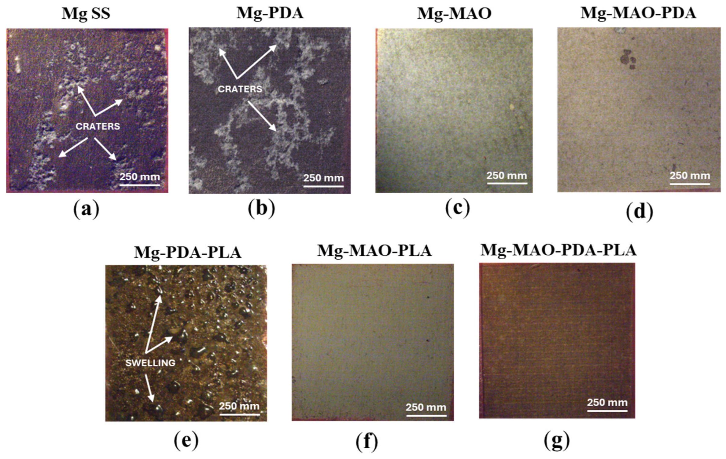
  • The beneficial effect of the applied coatings was highlighted in the electrochemical tests, which showed a better response for surface-modified specimens in terms of corrosion kinetics. In particular, from the potentiodynamic polarization was observed an improvement in the corrosion current density and the corrosion potential for the anodized specimen. Different behavior was apparent after the application of the polydopamine on the anodic oxide, which reduced the corrosion potential, but it involved a passivity range by ennobling the corrosion behavior. The EIS analysis confirmed the results of the potentiodynamic polarization, and during the immersion time of 168 h, it revealed the best corrosion resistance for the specimen covered with all coatings.
This research has demonstrated that a careful design of the coating system, in terms of the morphology and thickness of each layer composing it, may reduce the degradation process of magnesium alloys, thanks to the sealing of the oxide pores with a polydopamine layer and the presence of the PLA film, which could potentially improve the healing of the host tissues for biodegradable implants’ applications due to the tailored pattern that could be used to apply it.

Author Contributions

Conceptualization, A.A. and T.M.; methodology, A.A.; validation, A.A., P.R. and A.D.S.; formal analysis, A.A.; investigation, A.A., F.D., P.R. and G.S.; data curation, A.A., G.S. and F.D.; writing—original draft preparation, A.A.; writing—review and editing, A.A. and P.R.; visualization A.D.S.; supervision, A.A. and T.M. All authors have read and agreed to the published version of the manuscript.

Funding

The research presented in this contribution was partially financed by the Government of Italy Ministry of Education University and Research to the Department of Chemical Engineering, Materials and Industrial Production of the University of Napoli Federico II through the PON R&I 2014–2020—Axis IV “Education and research for recovery—REACT-EU” Action IV.6—“Research contracts on Green issues” (Ministero dell’Istruzione, dell’Università e della Ricerca: PON_GREEN_RTDA_2021_25).

Data Availability Statement

The original contributions presented in this study are included in the article. Further inquiries can be directed to the corresponding author(s).

Conflicts of Interest

The authors declare no conflicts of interest.

References

  1. Amukarimi, S.; Mozafari, M. Biodegradable Magnesium-based Biomaterials: An Overview of Challenges and Opportunities. MedComm 2021, 2, 123–144. [Google Scholar] [CrossRef]
  2. De Baaij, J.H.; Hoenderop, J.G.; Bindels, R.J. Magnesium in Man: Implications for Health and Disease. Physiol. Rev. 2015, 95, 1–46. [Google Scholar] [CrossRef] [PubMed]
  3. Zindani, D.; Kumar, K.; Paulo Davim, J. 4—Metallic Biomaterials—A Review. In Mechanical Behaviour of Biomaterials; Davim, J.P., Ed.; Woodhead Publishing: Sawston, UK, 2019; pp. 83–99. ISBN 978-0-08-102174-3. [Google Scholar]
  4. Kirkland, N.T. Magnesium Biomaterials: Past, Present and Future. Corros. Eng. Sci. Technol. 2012, 47, 322–328. [Google Scholar] [CrossRef]
  5. Witte, F. The History of Biodegradable Magnesium Implants: A Review: The THERMEC’2009 Biodegradable Metals. Acta Biomater. 2010, 6, 1680–1692. [Google Scholar] [CrossRef]
  6. Witte, F.; Fischer, J.; Nellesen, J.; Crostack, H.-A.; Kaese, V.; Pisch, A.; Beckmann, F.; Windhagen, H. In Vitro and in Vivo Corrosion Measurements of Magnesium Alloys. Biomaterials 2006, 27, 1013–1018. [Google Scholar] [CrossRef]
  7. Wu, C.S.; Zhang, Z.; Cao, F.H.; Zhang, L.J.; Zhang, J.Q.; Cao, C.N. Study on the Anodizing of AZ31 Magnesium Alloys in Alkaline Borate Solutions. Appl. Surf. Sci. 2007, 253, 3893–3898. [Google Scholar] [CrossRef]
  8. Dai, D.; Wang, H.; Li, J.-Z.; Wu, X.-D. Environmentally Friendly Anodization on AZ31 Magnesium Alloy. Trans. Nonferrous Met. Soc. China Engl. Ed. 2008, 18, s380–s384. [Google Scholar] [CrossRef]
  9. Zhang, Y.; Zhang, G.; Wei, M. Controlling the Biodegradation Rate of Magnesium Using Biomimetic Apatite Coating. J. Biomed. Mater. Res. B Appl. Biomater. 2009, 89B, 408–414. [Google Scholar] [CrossRef] [PubMed]
  10. Cheng, Y.-L.; Wu, H.-I.; Chen, Z.-H.; Wang, H.-M.; Zhang, Z.; Wu, Y.-W. Corrosion Properties of AZ31 Magnesium Alloy and Protective Effects of Chemical Conversion Layers and Anodized Coatings. Trans. Nonferrous Met. Soc. China Engl. Ed. 2007, 17, 502–508. [Google Scholar] [CrossRef]
  11. Dabalà, M.; Brunelli, K.; Napolitani, E.; Magrini, M. Cerium-Based Chemical Conversion Coating on AZ63 Magnesium Alloy. Surf. Coat. Technol. 2003, 172, 227–232. [Google Scholar] [CrossRef]
  12. Scharnagl, N.; Blawert, C.; Dietzel, W. Corrosion Protection of Magnesium Alloy AZ31 by Coating with Poly(Ether Imides) (PEI). Surf. Coat. Technol. 2009, 203, 1423–1428. [Google Scholar] [CrossRef]
  13. Raja, V.S.; Venugopal, A.; Saji, V.S.; Sreekumar, K.; Nair, R.S.; Mittal, M.C. Electrochemical Impedance Behavior of Graphite-Dispersed Electrically Conducting Acrylic Coating on AZ31 Magnesium Alloy in 3.5 Wt.% NaCl Solution. Prog. Org. Coat. 2010, 67, 12–19. [Google Scholar] [CrossRef]
  14. Kim, Y.-K.; Park, I.-S.; Lee, K.-B.; Bae, T.-S.; Jang, Y.-S.; Oh, Y.-M.; Lee, M.-H. Effect upon Biocompatibility and Biocorrosion Properties of Plasma Electrolytic Oxidation in Trisodium Phosphate Electrolytes. Biointerphases 2016, 11, 011006. [Google Scholar] [CrossRef] [PubMed]
  15. Pezzato, L.; Gennari, C.; Franceschi, M.; Brunelli, K. Influence of Silicon Morphology on Direct Current Plasma Electrolytic Oxidation Process in AlSi10Mg Alloy Produced with Laser Powder Bed Fusion. Sci. Rep. 2022, 12, 14329. [Google Scholar] [CrossRef]
  16. Yeshmanova, G.; Blawert, C.; Serdechnova, M.; Wieland, D.C.F.; Starykevich, M.; Gazenbiller, E.; Höche, D.; Smagulov, D.; Zheludkevich, M.L. Effect of Electrolyte Composition on the Formation of PEO Coatings on AA2024 Aluminium Alloy. Surf. Interfaces 2024, 44, 103797. [Google Scholar] [CrossRef]
  17. Sarian, M.N.; Iqbal, N.; Sotoudehbagha, P.; Razavi, M.; Ahmed, Q.U.; Sukotjo, C.; Hermawan, H. Potential Bioactive Coating System for High-Performance Absorbable Magnesium Bone Implants. Bioact. Mater. 2022, 12, 42–63. [Google Scholar] [CrossRef]
  18. Peng, F.; Wang, D.; Tian, Y.; Cao, H.; Qiao, Y.; Liu, X. Sealing the Pores of PEO Coating with Mg-Al Layered Double Hydroxide: Enhanced Corrosion Resistance, Cytocompatibility and Drug Delivery Ability. Sci. Rep. 2017, 7, 8167. [Google Scholar] [CrossRef]
  19. Sreekanth, D.; Rameshbabu, N. Development and Characterization of MgO/Hydroxyapatite Composite Coating on AZ31 Magnesium Alloy by Plasma Electrolytic Oxidation Coupled with Electrophoretic Deposition. Mater. Lett. 2012, 68, 439–442. [Google Scholar] [CrossRef]
  20. Barberi, J.; Saqib, M.; Dmitruk, A.; Opitz, J.; Naplocha, K.; Beshchasna, N.; Spriano, S.; Ferraris, S. Characterization of Tannic Acid-Coated AZ31 Mg Alloy for Biomedical Application and Comparison with AZ91. Materials 2024, 17, 343. [Google Scholar] [CrossRef]
  21. Li, X.; Cong, Y.; Sui, J.; Li, X. An Investigation on the Degradation Behaviors of Mg Wires/PLA Composite for Bone Fixation Implants: Influence of Wire Content and Load Mode. Sci. Eng. Compos. Mater. 2021, 28, 39–47. [Google Scholar] [CrossRef]
  22. Butt, M.S.; Bai, J.; Wan, X.; Chu, C.; Xue, F.; Ding, H.; Zhou, G. Mg Alloy Rod Reinforced Biodegradable Poly-Lactic Acid Composite for Load Bearing Bone Replacement. Surf. Coat. Technol. 2017, 309, 471–479. [Google Scholar] [CrossRef]
  23. Negrescu, A.-M.; Necula, M.-G.; Gebaur, A.; Golgovici, F.; Nica, C.; Curti, F.; Iovu, H.; Costache, M.; Cimpean, A. In Vitro Macrophage Immunomodulation by Poly(ε-Caprolactone) Based-Coated AZ31 Mg Alloy. Int. J. Mol. Sci. 2021, 22, 909. [Google Scholar] [CrossRef]
  24. Heise, S.; Virtanen, S.; Boccaccini, A.R. Tackling Mg Alloy Corrosion by Natural Polymer Coatings—A Review. J. Biomed. Mater. Res. A 2016, 104, 2628–2641. [Google Scholar] [CrossRef] [PubMed]
  25. Keerthiga, G.; Prasad, M.J.N.V.; Vijayshankar, D.; Singh Raman, R.K. Polymeric Coatings for Magnesium Alloys for Biodegradable Implant Application: A Review. Materials 2023, 16, 4700. [Google Scholar] [CrossRef]
  26. Zeng, R.-C.; Cui, L.; Jiang, K.; Liu, R.; Zhao, B.-D.; Zheng, Y.-F. In Vitro Corrosion and Cytocompatibility of a Microarc Oxidation Coating and Poly (l-Lactic Acid) Composite Coating on Mg–1Li–1Ca Alloy for Orthopedic Implants. ACS Appl. Mater. Interfaces 2016, 8, 10014–10028. [Google Scholar] [CrossRef]
  27. Khalili, V.; Ghaleh, H.; Asl, H.N.; Ege, D.; Dikici, B.; Kaseem, M.; Breisch, M.; Frenzel, J.; Eggeler, G. Assessing the Properties of Biodegradable Magnesium Alloy AZ31 Protected by a Polymer Layer on a Plasma Electrolytic Oxidized (PEO) Surface. Surf. Coat. Technol. 2024, 487, 131002. [Google Scholar] [CrossRef]
  28. Muñoz, M.; Torres, B.; Mohedano, M.; Matykina, E.; Arrabal, R.; López, A.J.; Rams, J. PLA Deposition on Surface Treated Magnesium Alloy: Adhesion, Toughness and Corrosion Behaviour. Surf. Coat. Technol. 2020, 388, 125593. [Google Scholar] [CrossRef]
  29. Daavari, M.; Atapour, M.; Mohedano, M.; Matykina, E.; Arrabal, R.; Nesic, D. Biological Performance of Duplex PEO + CNT/PCL Coating on AZ31B Mg Alloy for Orthopedic and Dental Applications. J. Funct. Biomater. 2023, 14, 475. [Google Scholar] [CrossRef] [PubMed]
  30. Usmaniya, N.; Radhakrishna Pillai, S.; Palanivel, M.; Edalacheruvu, L.; Chennampalli, P.; Vaithiyanathan, P.; Parfenov, E.; Lingamaneni, R.K.; Nagumothu, R. Effect of Polycaprolactone Coating on the Corrosion and Biological Characteristics of Plasma Electrolytic Oxidised ZM21 Magnesium Alloy. Surf. Coat. Technol. 2023, 471, 129915. [Google Scholar] [CrossRef]
  31. Chafiq, M.; Chaouiki, A.; Salghi, R.; Ko, Y.G. Fabrication of Branch-like Aph@LDH-MgO Material through Organic-Inorganic Hybrid Conjugation for Excellent Anti-Corrosion Performance. J. Magnes. Alloys 2023, 11, 2469–2485. [Google Scholar] [CrossRef]
  32. Wei, Z.; Tian, P.; Liu, X.; Zhou, B. Hemocompatibility and Selective Cell Fate of Polydopamine-Assisted Heparinized PEO/PLLA Composite Coating on Biodegradable AZ31 Alloy. Colloids Surf. B Biointerfaces 2014, 121, 451–460. [Google Scholar] [CrossRef] [PubMed]
  33. Silverman, H.G.; Roberto, F.F. Understanding Marine Mussel Adhesion. Mar. Biotechnol. 2007, 9, 661–681. [Google Scholar] [CrossRef]
  34. Tian, P.; Xu, D.; Liu, X. Mussel-Inspired Functionalization of PEO/PCL Composite Coating on a Biodegradable AZ31 Magnesium Alloy. Colloids Surf. B Biointerfaces 2016, 141, 327–337. [Google Scholar] [CrossRef] [PubMed]
  35. Acquesta, A.; Russo, P.; Monetta, T. Plasma Electrolytic Oxidation Treatment of AZ31 Magnesium Alloy for Biomedical Applications: The Influence of Applied Current on Corrosion Resistance and Surface Characteristics. Crystals 2023, 13, 510. [Google Scholar] [CrossRef]
  36. Lee, H.; Dellatore, S.M.; Miller, W.M.; Messersmith, P.B. Mussel-Inspired Surface Chemistry for Multifunctional Coatings. Science 2007, 318, 426–430. [Google Scholar] [CrossRef]
  37. Monetta, T.; Acquesta, A.; Bellucci, F. Evaluation of Roughness and Electrochemical Behavior of Titanium in Biological Environment. Metall. Ital. 2014, 106, 13–21. [Google Scholar]
  38. Acquesta, A.; Carangelo, A.; Monetta, T. TiO2 Nanotubes on Ti Dental Implant. Part 3: Electrochemical Behavior in Hank’s Solution of Titania Nanotubes Formed in Ethylene Glycol. Metals 2018, 8, 489. [Google Scholar] [CrossRef]
  39. Pourbaix, M. Atlas of Electrochemical Equilibria in Aqueous Solutions; National Association of Corrosion Engineers: Houston, TX, USA, 1974; ISBN 978-0-915567-98-0. [Google Scholar]
  40. Zhou, Z.; Zheng, B.; Lang, H.; Qin, A.; Ou, J. Corrosion Resistance and Biocompatibility of Polydopamine/Hyaluronic Acid Composite Coating on AZ31 Magnesium Alloy. Surf. Interfaces 2020, 20, 100560. [Google Scholar] [CrossRef]
  41. Carangelo, A.; Acquesta, A.; Monetta, T. Durability of AZ31 Magnesium Biodegradable Alloys Polydopamine Aided. Part 2: Ageing in Hank’s Solution. J. Magnes. Alloys 2019, 7, 218–226. [Google Scholar] [CrossRef]
  42. Chu, C.L.; Han, X.; Xue, F.; Bai, J.; Chu, P.K. Effects of Sealing Treatment on Corrosion Resistance and Degradation Behavior of Micro-Arc Oxidized Magnesium Alloy Wires. Appl. Surf. Sci. 2013, 271, 271–275. [Google Scholar] [CrossRef]
  43. Ghanbari, A.; Bordbar-Khiabani, A.; Warchomicka, F.; Sommitsch, C.; Yarmand, B.; Zamanian, A. PEO/Polymer Hybrid Coatings on Magnesium Alloy to Improve Biodegradation and Biocompatibility Properties. Surf. Interfaces 2023, 36, 102495. [Google Scholar] [CrossRef]
  44. Wu, T.; Blawert, C.; Serdechnova, M.; Karlova, P.; Dovzhenko, G.; Florian Wieland, D.C.; Stojadinovic, S.; Vasilic, R.; Wang, L.; Wang, C.; et al. Role of Phosphate, Silicate and Aluminate in the Electrolytes on PEO Coating Formation and Properties of Coated Ti6Al4V Alloy. Appl. Surf. Sci. 2022, 595, 153523. [Google Scholar] [CrossRef]
  45. Schlüter, K.; Zamponi, C.; Piorra, A.; Quandt, E. Comparison of the Corrosion Behaviour of Bulk and Thin Film Magnesium Alloys. Corros. Sci. 2010, 52, 3973–3977. [Google Scholar] [CrossRef]
  46. Farshid, S.; Kharaziha, M.; Atapour, M.; Di Franco, F.; Santamaria, M. Duplex Plasma Electrolytic Oxidation/Hydroxyapatite- Polydopamine Coating on WE43 Alloy for Bone Implants: Long-Term Corrosion Resistance and Biological Properties. Surf. Coat. Technol. 2024, 493, 131262. [Google Scholar] [CrossRef]
  47. Barati Darband, G.; Aliofkhazraei, M.; Hamghalam, P.; Valizade, N. Plasma Electrolytic Oxidation of Magnesium and Its Alloys: Mechanism, Properties and Applications. J. Magnes. Alloys 2017, 5, 74–132. [Google Scholar] [CrossRef]
  48. Li, N.; Ling, N.; Fan, H.; Liang, K.; Zhang, J.; Wang, L. Smart Functionalization of PEO Coating on AZ31B Magnesium Alloy by a Novel Facile One-Step Sealing Method. Surf. Coat. Technol. 2023, 467, 129674. [Google Scholar] [CrossRef]
  49. Cai, S.; Wu, C.; Yang, W.; Liang, W.; Yu, H.; Liu, L. Recent Advance in Surface Modification for Regulating Cell Adhesion and Behaviors. Nanotechnol. Rev. 2020, 9, 971–989. [Google Scholar] [CrossRef]
  50. Walboomers, X.; Croes, H.; Ginsel, L.; Jansen, J. Contact Guidance of Rat Fibroblasts on Various Implant Materials. J. Biomed. Mater. Res. 1999, 47, 204–212. [Google Scholar] [CrossRef]
  51. Rusen, L.; Cazan, M.; Mustaciosu, C.; Filipescu, M.; Sandel, S.; Zamfirescu, M.; Dinca, V.; Dinescu, M. Tailored Topography Control of Biopolymer Surfaces by Ultrafast Lasers for Cell–Substrate Studies. Appl. Surf. Sci. 2014, 302, 256–261. [Google Scholar] [CrossRef]
  52. Parandakh, A.; Anbarlou, A.; Tafazzoli-Shadpour, M.; Ardeshirylajimi, A.; Khani, M. Substrate Topography Interacts with Substrate Stiffness and Culture Time to Regulate Mechanical Properties and Smooth Muscle Differentiation of Mesenchymal Stem Cells. Colloids Surf. B Biointerfaces 2018, 173, 194–201. [Google Scholar] [CrossRef]
  53. Shukla, A.; Slater, J.H.; Culver, J.C.; Dickinson, M.E.; West, J.L. Biomimetic Surface Patterning Promotes Mesenchymal Stem Cell Differentiation. ACS Appl. Mater. Interfaces 2016, 8, 21883–21892. [Google Scholar] [CrossRef] [PubMed]
  54. Ber, S.; Torun Köse, G.; Hasırcı, V. Bone Tissue Engineering on Patterned Collagen Films: An in Vitro Study. Biomaterials 2005, 26, 1977–1986. [Google Scholar] [CrossRef] [PubMed]
  55. Nikkhah, M.; Edalat, F.; Manoucheri, S.; Khademhosseini, A. Engineering Microscale Topographies to Control the Cell–Substrate Interface. Biomaterials 2012, 33, 5230–5246. [Google Scholar] [CrossRef] [PubMed]
  56. Nikkhah, M.; Strobl, J.S.; De Vita, R.; Agah, M. The Cytoskeletal Organization of Breast Carcinoma and Fibroblast Cells inside Three Dimensional (3-D) Isotropic Silicon Microstructures. Biomaterials 2010, 31, 4552–4561. [Google Scholar] [CrossRef] [PubMed]
  57. Altomare, L.; Gadegaard, N.; Visai, L.; Tanzi, M.C.; Farè, S. Biodegradable Microgrooved Polymeric Surfaces Obtained by Photolithography for Skeletal Muscle Cell Orientation and Myotube Development. Acta Biomater. 2010, 6, 1948–1957. [Google Scholar] [CrossRef]
  58. Song, G.L.; Atrens, A. Corrosion Mechanisms of Magnesium Alloys. Adv. Eng. Mater. 1999, 1, 11–33. [Google Scholar] [CrossRef]
  59. Nachtsheim, J.; Ma, S.; Burja, J.; Batič, B.Š.; Markert, B. Tuning the Long-Term Corrosion Behaviour of Biodegradable WE43 Magnesium Alloy by PEO Coating. Surf. Coat. Technol. 2023, 474, 130115. [Google Scholar] [CrossRef]
  60. Liu, L.J.; Schlesinger, M. Corrosion of Magnesium and Its Alloys. Corros. Sci. 2009, 51, 1733–1737. [Google Scholar] [CrossRef]
  61. Standing Committee on the Scientific Evaluation of Dietary Reference Intakes. Dietary Reference Intakes for Calcium, Phosphorus, Magnesium, Vitamin D, and Fluoride; National Academies Press: Washington, DC, USA, 1999. [Google Scholar]
  62. CHENG, Y.; QIN, T.; WANG, H.; ZHANG, Z. Comparison of Corrosion Behaviors of AZ31, AZ91, AM60 and ZK60 Magnesium Alloys. Trans. Nonferrous Met. Soc. China 2009, 19, 517–524. [Google Scholar] [CrossRef]
  63. Zhang, F.; Ma, A.; Song, D.; Jiang, J.; Lu, F.; Zhang, L.; Yang, D.; Chen, J. Improving In-Vitro Biocorrosion Resistance of Mg-Zn-Mn-Ca Alloy in Hank’s Solution through Addition of Cerium. J. Rare Earths 2015, 33, 93–101. [Google Scholar] [CrossRef]
  64. Johnston, S.; Shi, Z.; Atrens, A. The Influence of pH on the Corrosion Rate of High-Purity Mg, AZ91 and ZE41 in Bicarbonate Buffered Hanks’ Solution. Corros. Sci. 2015, 101, 182–192. [Google Scholar] [CrossRef]
  65. Han, G.; Lee, J.-Y.; Kim, Y.-C.; Park, J.H.; Kim, D.-I.; Han, H.-S.; Yang, S.-J.; Seok, H.-K. Preferred Crystallographic Pitting Corrosion of Pure Magnesium in Hanks’ Solution. Corros. Sci. 2012, 63, 316–322. [Google Scholar] [CrossRef]
  66. Zeng, R.-C.; Sun, L.; Zheng, Y.-F.; Cui, H.-Z.; Han, E.-H. Corrosion and Characterisation of Dual Phase Mg–Li–Ca Alloy in Hank’s Solution: The Influence of Microstructural Features. Corros. Sci. 2014, 79, 69–82. [Google Scholar] [CrossRef]
  67. Bukovinová, L.; Hadzima, B. Electrochemical Characteristics of Magnesium Alloy AZ31 in Hank’s Solution. Corros. Eng. Sci. Technol. 2012, 47, 352–357. [Google Scholar] [CrossRef]
  68. Xin, Y.; Liu, C.; Zhang, X.; Tang, G.; Tian, X.; Chu, P.K. Corrosion Behavior of Biomedical AZ91 Magnesium Alloy in Simulated Body Fluids. J. Mater. Res. 2007, 22, 2004–2011. [Google Scholar] [CrossRef]
  69. Mena Morcillo, E.; Veleva, L. Degradation of AZ31 and AZ91 Magnesium Alloys in Different Physiological Media: Effect of Surface Layer Stability on Electrochemical Behaviour. J. Magnes. Alloys 2020, 8, 667–675. [Google Scholar] [CrossRef]
  70. Ghanbari, A.; Warchomicka, F.; Sommitsch, C.; Zamanian, A. Investigation of the Oxidation Mechanism of Dopamine Functionalization in an AZ31 Magnesium Alloy for Biomedical Applications. Coatings 2019, 9, 584. [Google Scholar] [CrossRef]
  71. Xiang, N.; Song, R.; Zhuang, J.; Song, R.; Lu, X.; Su, X. Effects of Current Density on Microstructure and Properties of Plasma Electrolytic Oxidation Ceramic Coatings Formed on 6063 Aluminum Alloy. Trans. Nonferrous Met. Soc. China 2016, 26, 806–813. [Google Scholar] [CrossRef]
  72. Li, Y.; Li, H.; Xiong, Q.; Wu, X.; Zhou, J.; Wu, J.; Wu, X.; Qin, W. Multipurpose Surface Functionalization on AZ31 Magnesium Alloy by Atomic Layer Deposition: Tailoring the Corrosion Resistant and Electrical Performance. Nanoscale 2017, 9, 8591–8599. [Google Scholar] [CrossRef] [PubMed]
  73. Jothi, V.; Adesina, A.Y.; Rahman, M.M.; Kumar, A.M.; Ram, J.S.N. Improved Adhesion and Corrosion Resistant Performance of Polyurethane Coatings on Anodized Mg Alloy for Aerospace Applications. J. Mater. Eng. Perform. 2020, 29, 2586–2596. [Google Scholar] [CrossRef]
  74. ASTM G102-89 (Reapproved 2015); Standard Practice for Calculation of Corrosion Rates and Related Information from Electrochemical Measurements. ASTM International: West Conshohocken, PA, USA, 2015.
  75. Zeng, R.; Jun, C.; Dietzel, W.; Hort, N.; Kainer, K. Electrochemical Behavior of Magnesium Alloys in Simulated Body Fluids. Trans. Nonferrous Met. Soc. China 2007, 17, s166–s170. [Google Scholar]
  76. Huang, J.; Li, Z.; Liaw, B.Y.; Zhang, J. Graphical Analysis of Electrochemical Impedance Spectroscopy Data in Bode and Nyquist Representations. J. Power Sources 2016, 309, 82–98. [Google Scholar] [CrossRef]
  77. Singer, F.; Schlesak, M.; Mebert, C.; Höhn, S.; Virtanen, S. Corrosion Properties of Polydopamine Coatings Formed in One-Step Immersion Process on Magnesium. ACS Appl. Mater. Interfaces 2015, 7, 26758–26766. [Google Scholar] [CrossRef] [PubMed]
  78. Liu, Y.; Liu, H.; Yuan, D.; Chen, S.; Zhu, C.; Chen, K. The Effect of Polylactic Acid Ordering on the Long-Term Corrosion Protection Capacity of Biodegradable Magnesium Alloys. Int. J. Biol. Macromol. 2024, 282, 135549. [Google Scholar] [CrossRef]
  79. Alabbasi, A.; Liyanaarachchi, S.; Kannan, M.B. Polylactic Acid Coating on a Biodegradable Magnesium Alloy: An in Vitro Degradation Study by Electrochemical Impedance Spectroscopy. Thin Solid Films 2012, 520, 6841–6844. [Google Scholar] [CrossRef]
  80. Acquesta, A.; Russo, P.; Monetta, T. Surface Engineering of Magnesium Alloys for the Next Generation of Biodegradable Device; Mechanisms and Machine Science; Springer: Cham, Switzerland, 2024; Volume 162, pp. 376–385. [Google Scholar]
  81. Monetta, T.; Acquesta, A. Magnesium-Based Biomedical Devices Degradation Control by Means of Multilayer Coatings. In Key Engineering Materials; Trans Tech Publications Ltd.: Bäch, Switzerland, 2023; Volume 967, pp. 137–142. [Google Scholar]
  82. Xin, Y.; Huo, K.; Tao, H.; Tang, G.; Chu, P.K. Influence of Aggressive Ions on the Degradation Behavior of Biomedical Magnesium Alloy in Physiological Environment. Acta Biomater. 2008, 4, 2008–2015. [Google Scholar] [CrossRef]
  83. Seyfoori, A.; Mirdamadi, S.; Khavandi, A.; Raufi, Z.S. Biodegradation Behavior of Micro-Arc Oxidized AZ31 Magnesium Alloys Formed in Two Different Electrolytes. Appl. Surf. Sci. 2012, 261, 92–100. [Google Scholar] [CrossRef]
Figure 1. Layout of electrochemical cell employed for the anodization treatment.
Metals 15 00146 g001
Figure 2. Scheme of the structure of the specimens after anodization, bio-inspired coating deposition, and PLA application.
Metals 15 00146 g002
Figure 3. Picture of specimens: untreated (a), after polydopamine layer deposition (b), after anodization (c), after anodization and polydopamine layer deposition (d), and after anodization and polydopamine layer and PLA deposition (e).
Metals 15 00146 g003
Figure 4. SEM observations of specimens: untreated (a), after polydopamine layer deposition (b), after anodization (c), after anodization and polydopamine layer deposition (d), after anodization and polydopamine layer and PLA film deposition (e), and magnification of the Mg-MAO specimens (f).
Metals 15 00146 g004
Figure 5. SEM cross-sectional view of the specimen after the micro-arc oxidation (MAO) treatment.
Metals 15 00146 g005
Figure 6. EDS spectra of specimens: untreated (a), after polydopamine layer deposition (b), after anodization (c), after anodization and polydopamine layer deposition (d), and after anodization and polydopamine layer and PLA deposition (e).
Metals 15 00146 g006
Figure 7. SEM cross-sectional view of the specimen after the micro-arc oxidation treatment, polydopamine deposition, and PLA hot pressing.
Metals 15 00146 g007
Figure 8. XRD spectra of untreated and anodized samples.
Metals 15 00146 g008
Figure 9. Diagram of micro-hardness measurements results obtained from samples.
Metals 15 00146 g009
Figure 10. Three-dimensional roughness graphs obtained through the confocal laser scanning microscopy of specimens: untreated (a), after polydopamine layer deposition (b), after anodization (c), and after anodization and polydopamine layer deposition (d).
Metals 15 00146 g010
Figure 11. (a) Three-dimensional graph of Mg-MAO-PDA-PLA specimen obtained through confocal laser scanning microscopy; (b) horizontal and (c) vertical profiles extracted from the 3D graph.
Metals 15 00146 g011
Figure 12. Potentiodynamic polarization scans of specimens obtained via immersion in the solution of Hanks at 37 °C considering the geometrical area (a) and effective area (b).
Metals 15 00146 g012
Figure 13. Bode plots as |Z| (a) and phase angle (b) of specimens recorded at the beginning of immersion in the solution of Hanks at 37 °C.
Metals 15 00146 g013
Figure 14. Nyquist plots of the samples without the PLA film at the beginning of the immersion test (a) and magnification (b).
Metals 15 00146 g014
Figure 15. Nyquist plots of the samples covered by the PLA film after at the beginning of the immersion test.
Metals 15 00146 g015
Figure 16. Bode plots as |Z| (a) and the phase angle (b) of the specimens recorded after 168 h of the immersion in the solution of Hanks at 37 °C.
Metals 15 00146 g016
Figure 17. Nyquist plots of all samples after 168 h of immersion testing. (a) Without PLA film. (b) Covered with PLA film. (c) Magnification of samples with PLA.
Metals 15 00146 g017
Figure 18. Surface appearance at the end of the EIS measurements conducted for 168 h in the solution of Hanks at 37 °C of Mg SS (a), Mg-PDA (b), Mg-MAO (c), Mg-MAO-PDA (d), Mg-PDA-PLA (e), Mg-MAO-Pla (f), and Mg-MAO-PDA-PLA (g).
Metals 15 00146 g018
Table 1. Average surface roughness parameters evaluated by means of laser confocal scanning microscope acquisitions.
Sa (µm)Sq (µm)Sp (µm)Sv (µm)SkuSskSdqSdr (%)
Mg SS0.3 ± 0.050.3 ± 0.023.1 ± 0.41.2 ± 0.434.4 ± 0.20.1 ± 0.030.2 ± 0.012.1 ± 0.05
Mg-MAO1.7 ± 0.22.4 ± 0.18.0 ± 0.214.7 ± 1.36.4 ± 0.4−1.4 ± 0.024.7 ± 0.05289.7 ± 12
Mg-PDA1.3 ± 0.31.7 ± 0.37.1 ± 0.35.8 ± 0.23.7 ± 0.20.5 ± 0.011.2 ± 0.0239.7 ± 2.1
Mg-MAO-PDA1.2 ± 0.21.6 ± 0.35.4 ± 0.211.4 ± 0.55.9 ± 0.2−0.8 ± 0.021.0 ± 0.0549.4 ± 1.6
Table 2. Corrosion parameters evaluated from the potentiodynamic polarization curves.
SpecimensCorrosion
Potential,
V vs. OCP
Corrosion Current Density,
A/cm2
Passivity Current Density,
A/cm2
Mg SS−1.48 ± 0.2(2.65± 0.3) × 10−5-
Mg-MAO−1.32 ± 0.4(5.99 ± 0.8) × 10−10-
Mg-PDA−1.49 ± 0.2(1.94 ± 0.3) × 10−7-
Mg-MAO-PDA−1.50 ± 0.3-(7.35 ± 0.4) × 10−8
Disclaimer/Publisher’s Note: The statements, opinions and data contained in all publications are solely those of the individual author(s) and contributor(s) and not of MDPI and/or the editor(s). MDPI and/or the editor(s) disclaim responsibility for any injury to people or property resulting from any ideas, methods, instructions or products referred to in the content.

