Article

Thin Film Fragmentation Testing: A Refined Screening Method for Estimating Relative Intrinsic Ductility of Refractory Metals

by
Taohid Bin Nur Tuhser
and
Thomas John Balk
*
Department of Chemical and Materials Engineering, University of Kentucky, Lexington, KY 40506, USA
*
Author to whom correspondence should be addressed.
Metals 2025, 15(10), 1144; https://doi.org/10.3390/met15101144
Submission received: 5 September 2025 / Revised: 4 October 2025 / Accepted: 8 October 2025 / Published: 15 October 2025
(This article belongs to the Special Issue Fracture and Fatigue of Advanced Metallic Materials)

Abstract

Refractory metals typically exhibit limited room temperature ductility, hampering their widespread application. Recent advances in refractory high-entropy alloys have focused on finding optimum combinations of strength and ductility but require exploring vast compositional spaces. To facilitate such a search process, a method for fast assessment of intrinsic ductility would be highly advantageous. Herein, we propose a novel approach to screen for a refractory alloy’s ‘intrinsic ductility’ by leveraging the established technique of thin film fragmentation testing, which has been successfully used to evaluate stretchability of flexible electronics. We conducted in-depth investigations of sputtered tungsten thin films to identify the processing-induced extrinsic variables that can affect the crack onset strain (COS) under uniaxial loading. By tuning the process parameters for film deposition, Nb, Mo, Ta and W samples were fabricated with comparable thicknesses and residual stress levels. The films’ COS values were compared to the ductility levels of bulk counterpart materials, and the conditions for meaningful comparison are discussed. This approach offers a simple, inexpensive, and rapid means of screening based on relative intrinsic ductility of thin metal films and should also be applicable to the study of high-entropy alloy films.

1. Introduction

Refractory alloys are critical for technological advancement in sectors such as energy, transportation, and defense. Their combination of high melting point, hardness, corrosion resistance, and exceptional high-temperature strength makes them ideally suited for extreme application spaces, including hypersonic systems, corrosive reactor environments, and hard tooling applications. Despite these advantages, their broader adoption—such as replacing Ni-based superalloys in turbine blades—is limited by poor room-temperature ductility [1].
One can consider both extrinsic and intrinsic approaches to improving the ductility of an alloy. The extrinsic route involves microstructural engineering approaches such as grain size modification, controlled precipitation, etc., and can be achieved via fabrication processes including thermomechanical processing or heat treatment (for example, [2]). Conversely, intrinsic material properties can be adjusted solely by altering alloy composition and thereby changing the electronic structure of the material [3,4].
The development of high-entropy materials has led to a shift in traditional materials development strategies and has opened an extensive and largely untapped compositional space for exploration. By deliberately combining five or more elements in near-equiatomic ratios, this design strategy leverages the increase in configurational entropy to stabilize simple single-phase solid solutions. Since its inception, the entropy-driven approach has been extended beyond metallic alloys to a wide range of systems—including high-entropy oxides [5], carbides [6], and even polymers [7]—each expanding the boundaries of conventional material capabilities. Within the class of structural materials, refractory high-entropy alloys (RHEAs) have emerged as a promising new group of alloys that aim to achieve the ideal combination of high strength and ductility [8,9]. Researchers are dedicated to finding the optimal composition that can enhance the intrinsic ductility of RHEAs [4,9,10,11]. High-throughput experimentation and computational methods have been employed to screen new RHEA compositions [12,13,14]. The tensile properties are especially important for advancing these alloys, since limited room-temperature ductility remains a key barrier to fully leveraging their excellent high-temperature strength. However, the pace of generating tensile test results has been hindered by the complexity associated with fabricating and testing specimens, especially for those bulk refractory alloys that are brittle [8]. To overcome this challenge, efforts are ongoing to develop a simple, fast, and cost-effective alternative for characterizing the ductility of RHEAs [8,15,16,17].
Extracting the ‘intrinsic’ properties of a bulk sample can be complicated by certain process-dependent variables. For example, vacuum arc melting, a commonly used method for preparing tensile specimens, is conducted at very high temperatures (above 1800 °C for refractory alloys) and involves fast cooling during solidification, which can lead to accelerated high-temperature oxidation and inhomogeneous microstructure [18,19]. Even when alloy samples exist as a single-phase solid solution, the presence of dendritic microstructure, differences in grain size, grain boundary segregation, inclusion of casting defects, and oxidation during melting and solidification can significantly impact the tensile behavior [4,18]. Powder metallurgy is an alternative solid-state route that aims to utilize lower-temperature processing and achieve homogeneous structure. However, defects such as pores and inclusions are reported to be critical factors affecting the ductility of these alloys [20]. Hence, a more reliable method is needed to eliminate these variables and provide quantifiable results for comparison of intrinsic properties.
Ideally, tensile testing of freestanding thin films could provide an accurate characterization of their intrinsic fracture toughness. Modern film deposition techniques such as magnetron sputtering, performed in a high-vacuum environment at ambient temperature and with high-purity targets, can produce inclusion-free and homogenous microstructures. The small dimensions of the film allow dislocations to escape easily, thereby minimizing strain hardening in the absence of surfaces that are passivated or otherwise block dislocations. Film fracture should therefore depend only on internal structure. However, the preparation of freestanding films is not trivial for high-throughput studies due to the complex experimental setup and expensive, time-consuming sample preparation techniques that are required, such as lithography and focused ion beam milling. An alternative solution involves fragmentation testing of substrate-supported thin films. Fragmentation testing of thin films has recently received attention due to its ease of use, low cost, and potential for direct implementation in emerging technologies such as MEMS and flexible electronics [21,22,23]. This method assesses the ‘stretchability’ of flexible electronic devices under uniaxial straining and quantifies the outcome as crack onset strain (COS).
Although the fracture of substrate-supported thin films differs from that of freestanding thin films, the COS level is known to exhibit a strong dependence on film composition [24]. In recent years, fragmentation testing has been increasingly used in the HEA community to report mechanical properties of new alloys and to compare different compositions [25,26,27]. This method shows promise for addressing the long-standing challenge of rapidly generating tensile data across the vast RHEA compositional space. However, to adopt this technique more broadly and report results more reliably, it is essential to understand how process variables affect the measurements. To be specific, the combined mechanical response of substrate-supported films does not directly reflect the intrinsic ductility of the film, since the substrate dominates the overall behavior. In addition, extrinsic factors such as film thickness, adhesion, residual stress, and microstructure can significantly influence the results. In this study, we systematically examine these factors in refractory metals and discuss how intrinsic properties can be extracted from thin film fragmentation testing.
The first section of this manuscript focuses on the investigation of process variables with the aim of identifying and optimizing extrinsic factors. Specifically, we used tungsten (W) as the test material and produced thin films at varying chamber pressures and thickness levels, to understand the effects of these processing parameters on residual stress, microstructure, and, most importantly, COS.
In the latter part of this study, we compared the COS of thin films made from Nb, Mo, Ta, and W. These refractory metals can be categorized into two groups based on their bulk mechanical properties: ductile (Nb and Ta) versus brittle (W and Mo) [4]. While investigation of their fragmentation behavior is of particular interest in the context of flexible electronics, the primary focus of the current study is to determine whether thin film fragmentation tests can accurately replicate the trends in bulk ductility of these metals. Ultimately, this study seeks to leverage this understanding of refractory metal behavior and provide a cost-effective, readily accessible, and dependable alternative approach for assessing the relative ductility of the extensive composition spaces of RHEAs.

2. Methods

Thin films were deposited using an AJA ORION magnetron sputtering system (AJA International, Inc., Hingham, MA, USA) equipped with 2-inch diameter targets of 99.99% purity. The AJA ORION vacuum chamber was first pumped to a base pressure of approximately 10−8 torr and the substrate was loaded using a transfer arm without breaking the vacuum. The target-to-substrate distance was set to 55 mm during deposition. To ensure good adhesion, the substrate was cleaned for 90 s at 25 mtorr (3.33 Pa) with a 35 W RF bias. The chamber pressure was maintained using ultra-high purity argon gas, which was controlled using a manual valve. All films were deposited at room temperature using an AJA International DC power source set at 150 W. Deposition rates were determined individually for each metal target, and deposition times were adjusted accordingly to control the film thickness within 10 nm of the target value.
Two sets of substrates were used for each deposition condition. The first set consisted of dogbone samples with dimensions adhering to ASTM Standard D638-14 [28] (Type V sample dimensions), having a rectangular gauge section of 3.18 mm width and 9.53 mm length; these were prepared by punching through Kapton FPC (Flexible Printed Circuit) sheets of 125 µm thickness. The second set of substrates included 3-inch diameter Si (001) single-crystalline wafers for analysis of biaxial stress in deposited films.
Film thickness was measured from cross-section images using scanning electron microscopy (SEM; FEI Helios G3 dual-beam FIB-SEM system; FEI, Hillsboro, OR, USA). In-situ tensile testing was performed using an Instron 3345 (Instron®,Norwood, MA, USA) load frame with a 5 kN load cell and a 5 µm/s displacement rate. A second non-conductive grip was added to the metallic grip for in-situ measurement of thin film resistance, which was measured using a Keithley 2400 (Keithley Instruments & Products, Solon, OH, USA) sourcemeter in 4-wire sense mode. This experimental setup is based on the in-situ testing configuration utilized by Glushko and Cordill [29] (see Supplementary Materials: Figure S2). A preload of 1 N was applied before initiation of data recording, to mitigate unwanted bending of specimens during loading. Initial resistance, R0 was recorded for the films. The value of R0 was taken from the dogbone gauge length when the sample reached the 1 N preload. Two or three dogbone samples were tested for each film to confirm reproducibility. Both R0 and COS are reported for all samples below. While the number of tested samples may not be sufficient for meaningful statistical analysis, the experimentally measured values were found to exhibit scatter within 10% of their respective average value, affirming the reliability of the method employed here.
The crystal structure of thin films deposited on Kapton substrates was analyzed by X-ray diffraction (XRD; Siemens D500 Krystalloflex Diffractometer; Siemens AG, Karlsruhe, Germany) using the Bragg–Brentano geometry with a scan rate of 1°/min and a step size of 0.02°. The Scherrer equation was employed to determine crystallite size. The peaks exhibiting the highest intensities for each phase were chosen for analysis, and these were fitted using the Voigt function. Prior to calculating the crystallite sizes, instrumental broadening was measured and taken into consideration.
Film stress was measured for thin films on 3-inch (76.2 mm) Si single-crystalline wafers using laser scanning in a wafer curvature system (Toho FLX-2320; Toho Technology Inc., Chicago, IL, USA), with the net film curvature used for calculation of residual film stress using Stoney’s equation. The scans were conducted through the center of each wafer, covering the middle 60 mm of a given wafer diameter, i.e., excluding the outermost 8.1 mm near the wafer circumference. Measurements were taken for 0, 30, 60, 90, 120, and 150-degree orientations, and the average stress values calculated from these measurements had a standard deviation of less than 5%, indicating a biaxial stress state in the wafer that was independent of rotation about the substrate surface normal. Additionally, the stress state in dogbone samples was qualitatively confirmed through a visual inspection method, where curling of the substrate due to residual film stress provided a visual indication of the level of compressive (or tensile) stress.

3. Results and Discussion

Thin film fragmentation testing is used to monitor crack formation in thin films attached to substrates under uniaxial tensile loading. This test assumes strong film–substrate adhesion to prevent film failure before reaching the fracture strain. Detection of the fracture strain is achieved using in-situ techniques such as SEM, XRD, optical microscopy (OM), atomic force microscopy (AFM), or four-point probe (4PP) [30].
Microscopy-based methods involve incremental stretching and image tracking to identify the COS. COS accuracy depends on step size and scan area, with smaller steps and larger scans yielding more precise results. However, this approach can be time-consuming and unsuitable for rough or porous surfaces. It can also be subjective, relying on operator judgment. In contrast, in-situ resistance measurement during fragmentation testing, specifically using four-point probe (4PP), offers a simpler, more accurate approach [30,31]. It provides continuous data across the gauge length without requiring operator intervention for crack detection. This approach eliminates the need for multiple imaging steps, increasing the accuracy of results. Hence, our current study adopts the in-situ resistance-based method in order to realize these advantages.
The evolution of cracks in a thin film or coating during fragmentation testing can be divided into three stages [32]. Stage I is characterized by a strain-dependent increase in resistance and can be described by the following Equation [33]:
R R 0 = l l 0 2
where R is the resistance of the film at time t;
R 0 : resistance at t = 0;
l 0 : gauge length at t = 0;
l: gauge length at time t.
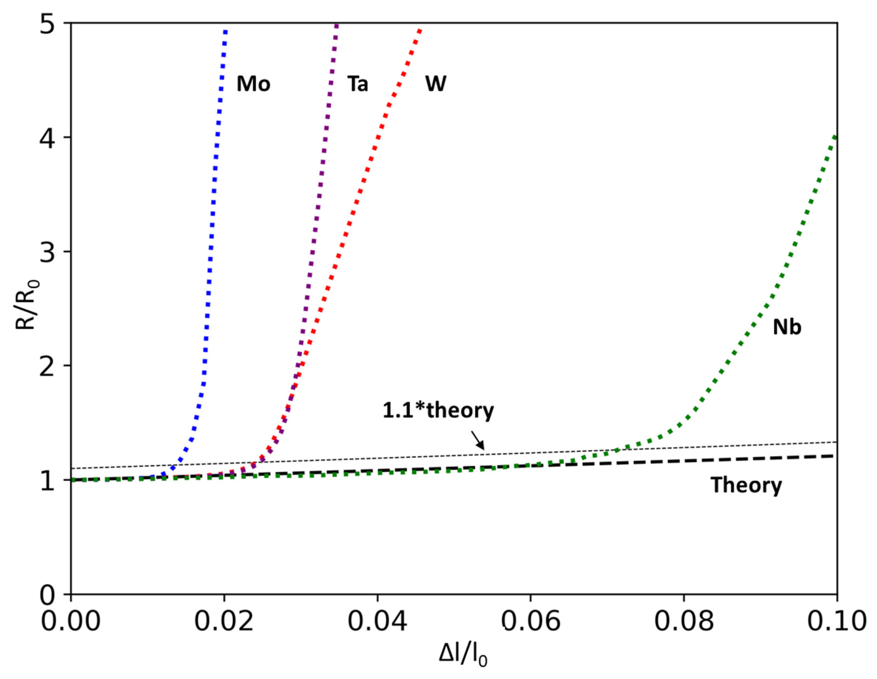
At the end of stage I, cracks begin to form in a direction perpendicular to the load axis, as a result of the coating reaching its fracture strength. The onset of perpendicular cracking can be detected through in-situ resistance measurements by observing a suitable change in the R/R0 ratio. The strain at which perpendicular cracks begin to form is known as the COS. In the current study, a 10% deviation from Equation (1) is taken as an indication that the sample has reached its COS [34,35,36].
To compare the COS of thin films with different compositions, it is crucial to understand and control the process parameters that can impact the COS. Residual stress is a major contributing factor that is nearly inevitable in sputtered thin films. The first section of the current study investigates the process parameters that affect residual stress and their respective impacts on COS, with a focus on tungsten as the film material.
Each deposition condition is assigned a unique material ID to enhance clarity and readability in subsequent sections, as shown in Table 1. This includes variations in chamber pressure for a constant film thickness of 180 nm, as well as changes in film thickness for a constant sputtering pressure of 3.5 mtorr.
Figure 1 presents the XRD plots of as-deposited W thin films. W_2.5mtorr and W_3.5mtorr films exhibit the α-BCC phase with a strong {110} fiber texture. This is typical for the sputter deposition process, where films grow with the close-packed planes parallel to the substrate [37]. Sputtered W films often form a metastable β phase with an A15 (cubic) structure [38]. The presence of this phase is primarily determined by the incorporation of residual oxygen in the sputtering system [39]. Other variables such as chamber pressure, deposition power, film thickness, temperature, or presence of an interlayer can also contribute to β phase formation [40,41]. In the current experiments, however, the β phase was not detected for sputtering pressures of 2.5 or 3.5 mtorr. This is likely due to the sputtering pressure being sufficiently low, thereby reducing the amount of residual oxygen in the system and also reducing the number of collisions with sputtering atoms, both of which favor the formation of the single-phase α-BCC structure. The W_4.0mtorr film has a multi-phase structure, with α-BCC as the primary phase. With further increases in the sputtering pressure to 4.5 mtorr, β-W becomes the major constituent.
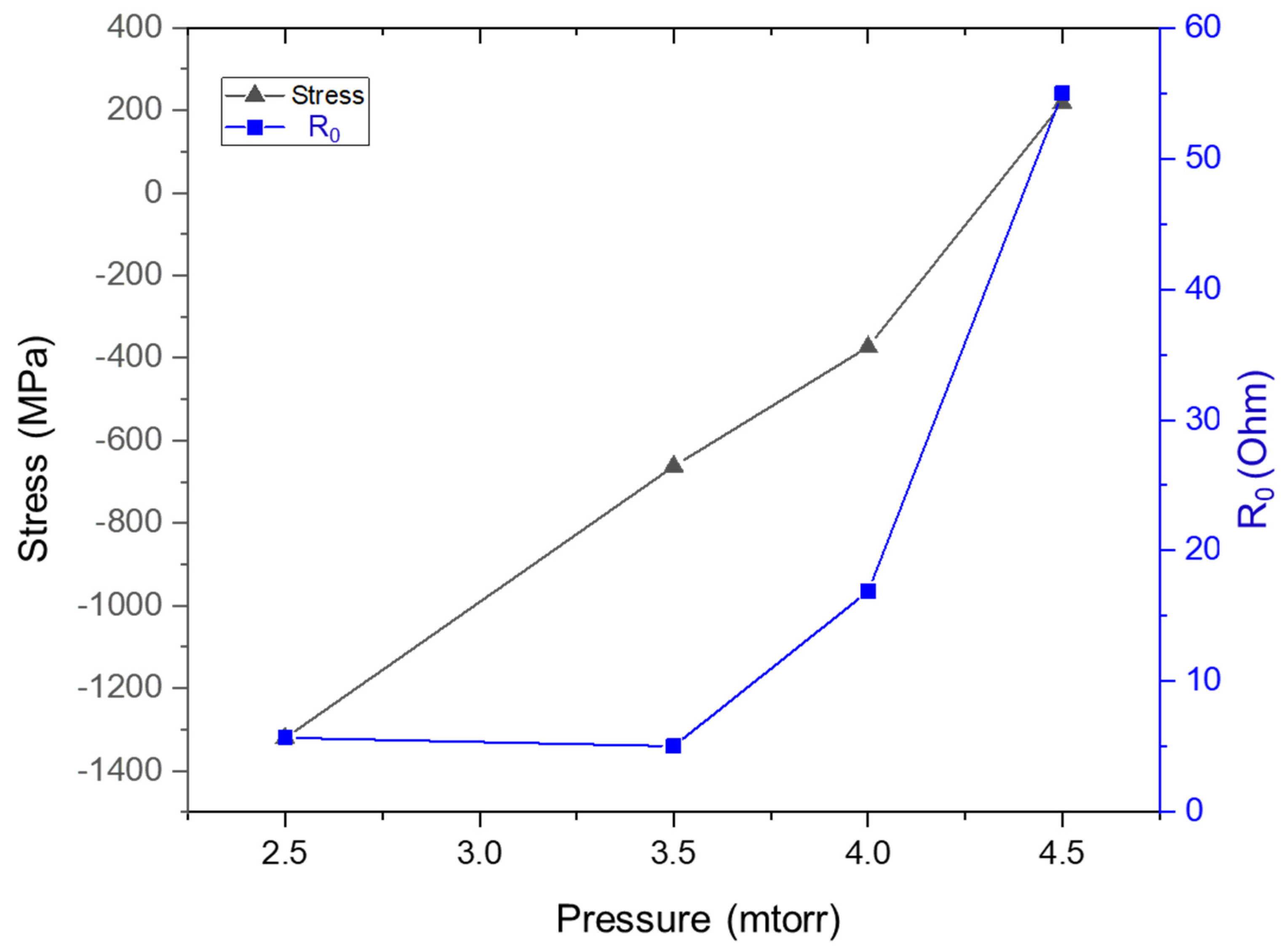
The residual stress in the film is strongly influenced by the chamber pressure during deposition, as shown in Figure 2. The W_2.5mtorr film exhibited the largest compressive stress of −1300 MPa, while the stress state changed to tensile +210 MPa for W_4.5mtorr. This pattern is consistent with other studies in the literature [42,43]. The pressure dependence of film stress state is related to the transport of particles from the target to the substrate through the argon atmosphere. At low sputtering pressures, sputtered atoms collide less frequently with the argon gas, resulting in a tightly packed columnar microstructure with high compressive stress. As the chamber pressure increases, the likelihood of collision increases, promoting tensile residual stress via the creation of free volume. This mechanism of stress generation is common in sputter deposition and is independent of the target material [39,44,45].
The change in initial resistance, R0, with chamber pressure can be explained by the phase evolution described in Figure 3. The metastable β phase has a resistivity of 1000–10,000 × 10−8 Ω-m, compared to 10–20 × 10−8 Ω-m for the α phase [46]. R0 is initially 5.68 Ω at the lowest pressure and remains unchanged at 3.5 mtorr. R0 increases with the emergence of the β phase in the W_4.0mtorr film, followed by a sharp increase to ~55 Ω for the W_4.5mtorr film.
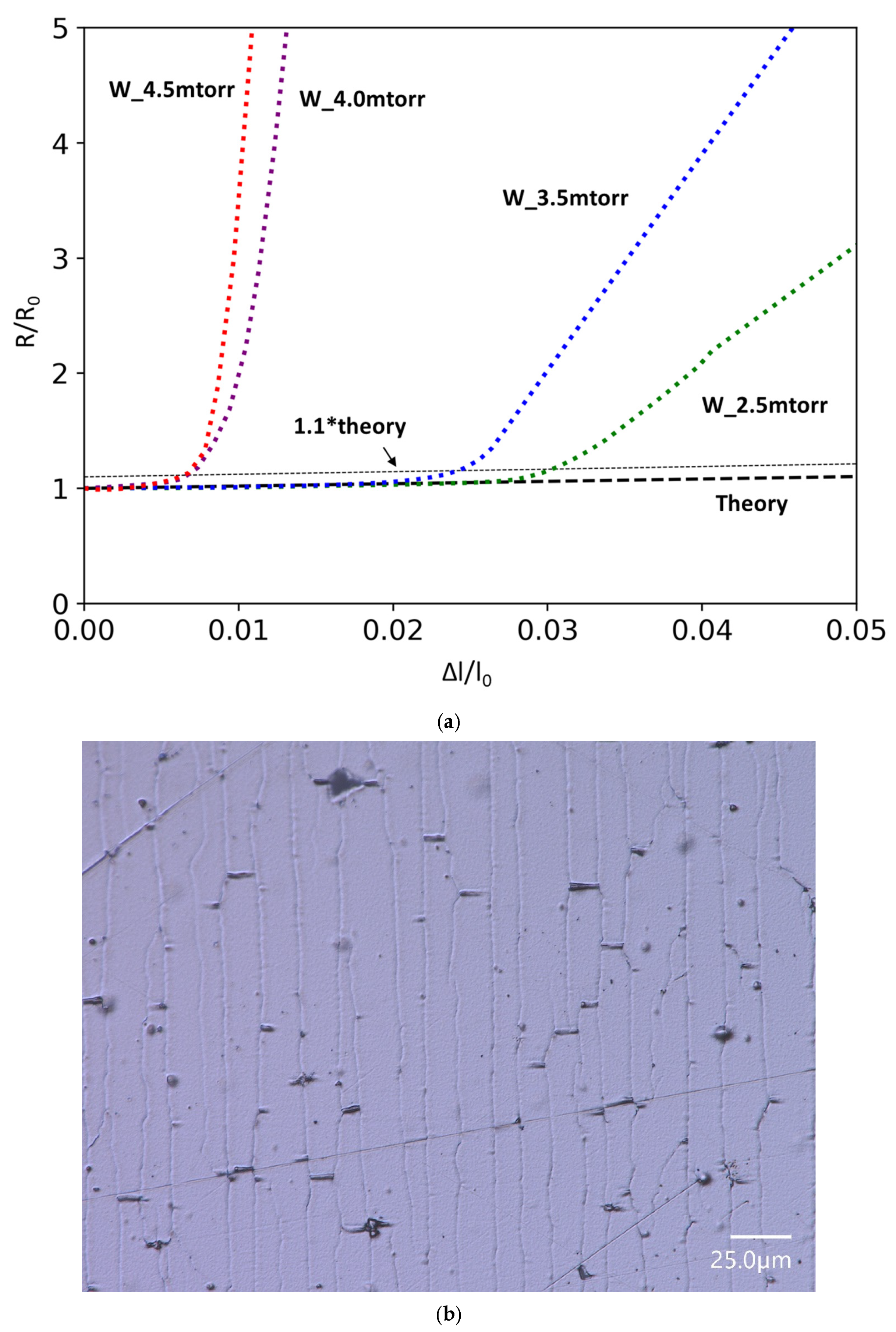
Figure 3a shows the normalized resistance of the film under uniaxial loading. Both the W_4.5mtorr and W_4.0mtorr samples show a low COS value of <1%. This can be attributed to their microstructures and residual stress states. These samples exhibit a mixture of phases and residual stresses that are more tensile (or less compressive) relative to the two films sputtered at lower pressures. The relatively larger crystallite size of the major β phase in W_4.5mtorr may explain the similar COS despite the presence of a tensile residual stress. As expected, W_2.5mtorr has the highest COS, followed by W_3.5mtorr.
These findings suggest that the COS is directly correlated with the residual stress state of the films. In the case of a compressive film stress, the external uniaxial load must overcome this compressive stress before the film will experience any tensile stress, thereby resulting in delayed fracture of the film. Previous research has studied this relationship for other coating materials [35,47]. An optical micrograph of a representative film-on-Kapton sample after tension testing beyond the COS is shown in Figure 3b. In this image, the load axis is horizontal, and perpendicular (vertical) cracks are observed at regular intervals. These perpendicular cracks result directly from the horizontal load. Additionally, short cracks parallel to the load axis are observed in Figure 3b. These short cracks result from lateral compression and buckling of the film, a phenomenon that provides useful insight into the continued deformation behavior of thin films and their adhesion to substrates. Film buckling can be monitored separately for indirect assessment of film properties, potentially including fracture toughness. Indeed, this is the subject of a related study completed as part of the author’s PhD dissertation [48] and will be published separately.
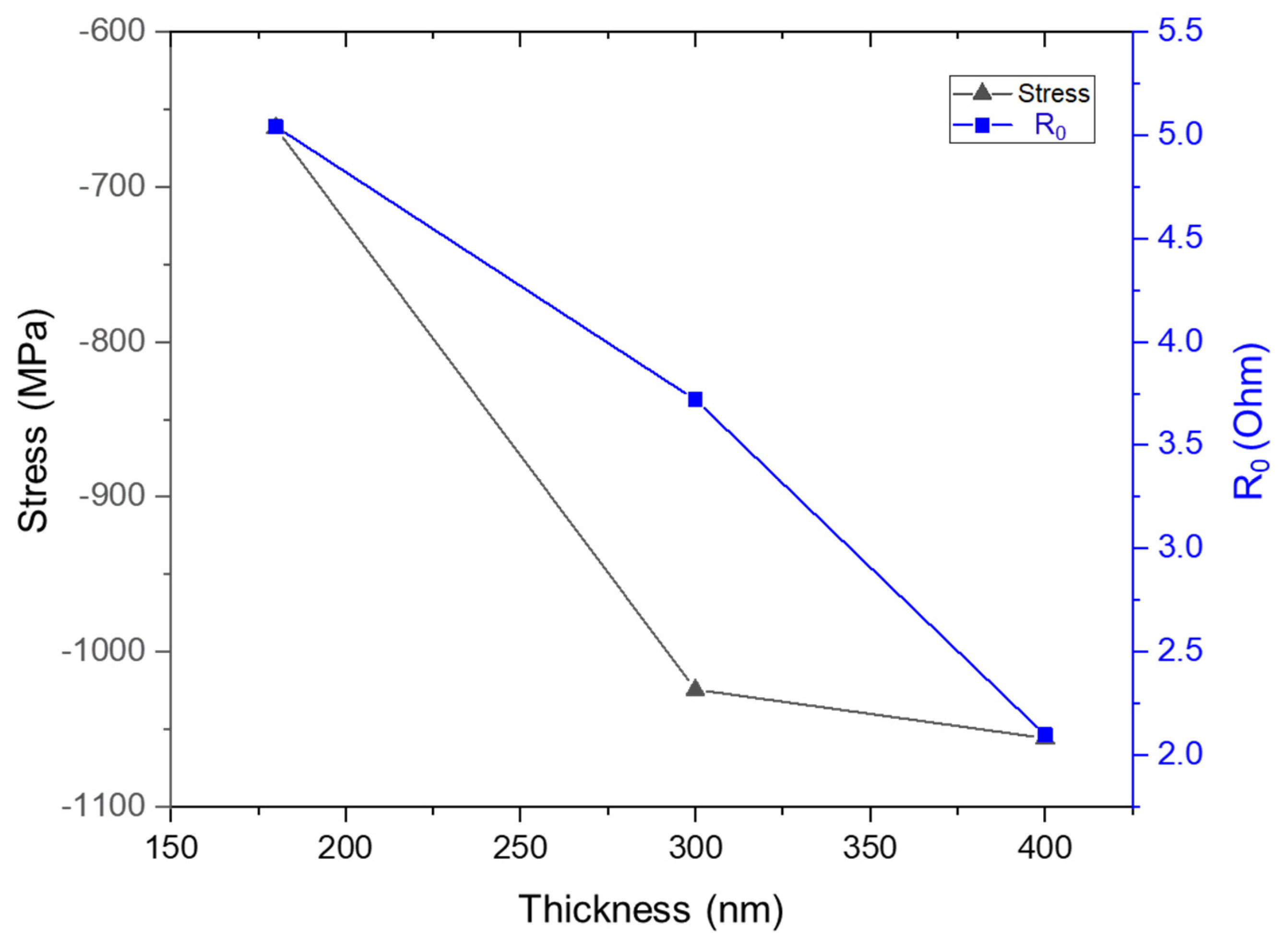
Figure 4 depicts the variation in residual stress and R0 with thickness. All three films have BCC structure with {110} texture (Supplementary Material: Figure S1). A compressive stress of −670 MPa exists in W_180nm but changes to −1000 MPa in W_300nm and remains constant in W_400nm. This is consistent with findings from other studies in the literature [42].
Initial resistance R0 decreases with increasing thickness and can occur due to electron scattering at grain boundaries and film surfaces. Choi et al. made a similar observation [49], where they identified surface scattering as the major contributor to the enhanced resistivity in thinner films. Similar observations were also made for sputtered Mo films [50].
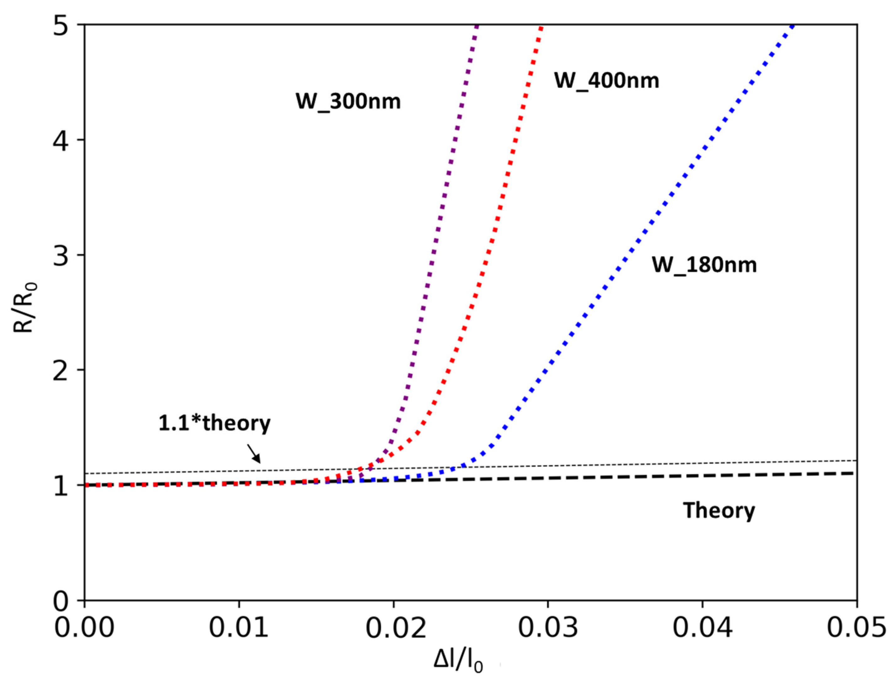
In Figure 5, the in-situ fragmentation test curves for W films of varying thickness are displayed. W_300nm and W_400nm, despite having higher compressive residual stress and slightly larger crystallite size, did not exhibit higher levels of COS. This appears to contradict the findings reported in the previous section, where a delay in COS (i.e., higher COS value) was observed for films with a compressive residual stress. These results suggest that the effect of film thickness variation is more significant than that of film stress in governing fracture behavior, at least in this range of film thickness. As thickness increases, the likelihood of defect accumulation also increases, which may act as a source of crack initiation, as was reported in another group’s study of sputter-deposited Cr films on polymer substrates [51].
The remainder of the current study presents a comparison of COS values for refractory metals. Considering the impact of residual stress and film thickness on COS, the film processing parameters were optimized to achieve the same thickness (180 nm) and a comparable level of compressive residual stress (approximately −650 MPa).
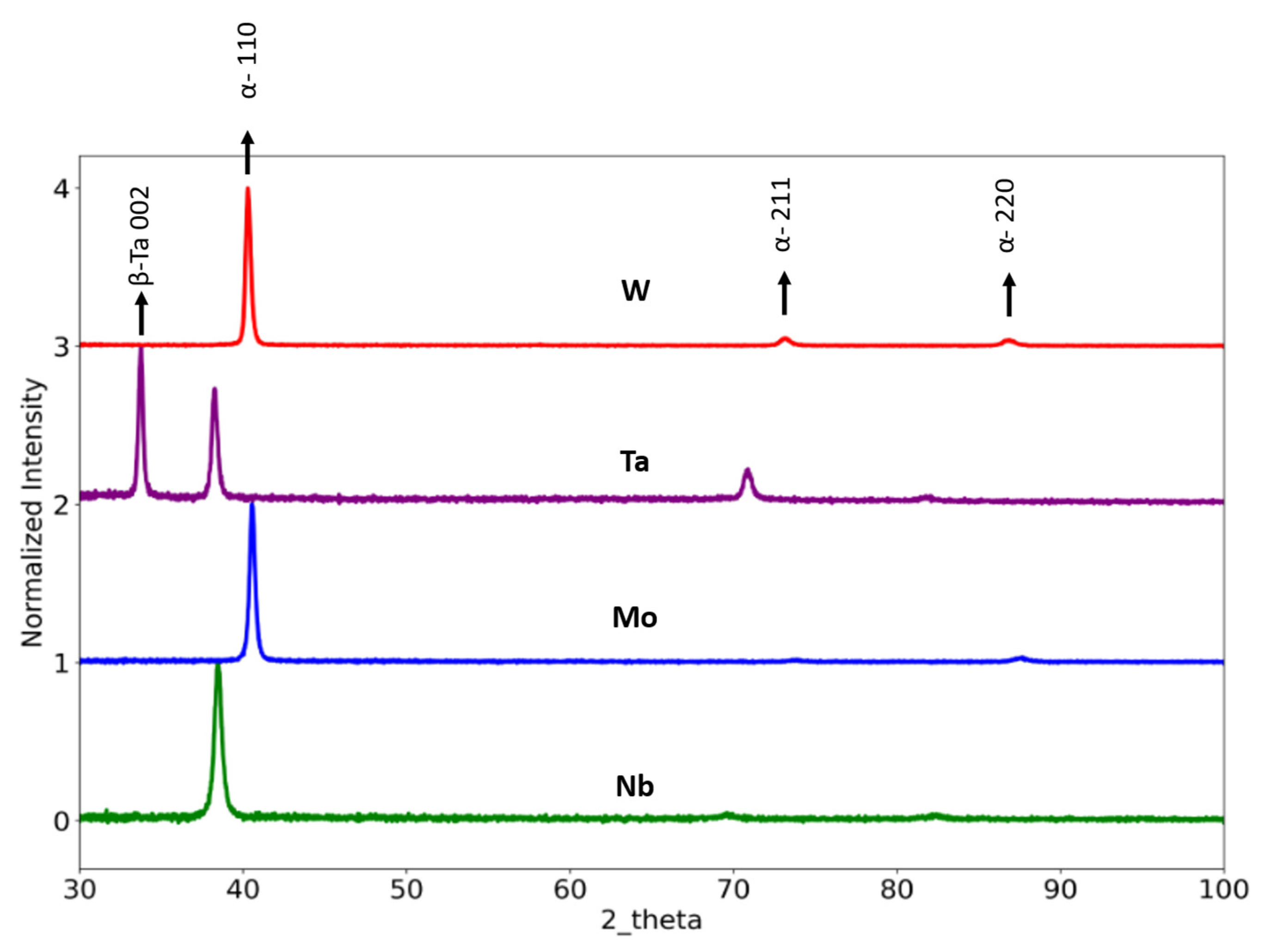
The results of XRD analysis of thin film samples are shown in Figure 6. For clarity, the peak intensities have been normalized after subtracting background noise. W, Mo and Nb films retained the BCC structure with a strong {110} texture; the smaller peaks in the range of 70° to 74° 2θ correspond to {211}-oriented grains. In the case of W, the Ar sputtering pressure used for this sample resulted in the formation of the α phase (only). However, unlike the other refractory films, Ta formed a mixture of α + β phases. The β phase has been identified as a metastable tetragonal phase unique to Ta thin films and has been studied extensively by other groups [52,53,54].
Initial electrical resistance at zero extension, R0, is reported in Table 2. For single-phase BCC films, the relative values of R0 follow a similar trend to that exhibited by the respective bulk refractory metals. The exceedingly high value of R0 for Ta is attributed to the higher resistivity of β-Ta. The reported resistivity of β-Ta is ~9 times that of α-Ta [55].
Figure 7 provides a comparison of in-situ electrical resistance measurements for the thin films under uniaxial tensile loading. The films were stretched up to 28% engineering strain. The plot shown here depicts the early stage of straining, to facilitate a comparison of COS for the different metals. W and Mo exhibit COS values below 3% strain, consistent with their low levels of bulk ductility at room temperature.
W is known to exhibit the lowest ductility level of the bulk refractory metals in the current study [4]. At first glance, the observation that W and Mo exhibit similar COS values may appear inconsistent with the bulk metal trend. However, this aspect of the thin film COS values can be linked to the deposition parameters used for Mo thin films. Unlike the other metal films, Mo was deposited with negative substrate bias (RF power) to achieve a target residual stress state similar to the stresses in other films. Negative bias in the substrate accelerates the positive ions towards the substrate. The resultant film microstructure can differ from regular (unbiased) deposition in terms of growth process and crystallinity, which can impact the mechanical behavior of the deposited film [57,58].
Additionally, Ta exhibited a similar COS to W. However, this result does not represent a contradiction of the trend for ductility of bulk refractory metals. The reason behind the low COS for Ta is attributed to its crystal structure. The metastable β phase is known to exhibit limited ductility [59], and this is consistent with the COS values determined in the current study.
As expected, Nb has the highest COS of the refractory metals studied here. It is important to note that all deposited films had a similar range of crystallite sizes, suggesting that variation in grain size can be excluded as a significant factor with respect to influence on COS.
Although the specific fracture conditions for substrate-supported films may be different from those applicable to bulk samples, it is still possible to make a qualitative comparison of relative ductility for bulk metals by using the in-situ fragmentation test approach in the current study, as along as certain test parameters are carefully considered. The following conditions must be met for reliable comparison:
  • The film–substrate adhesion must be sufficiently strong to force the film to undergo the strain imposed on it by the substrate, and thereby ensure uniform deformation before failure. If adhesion is weak, the film may delaminate in certain areas and partially behave like a free-standing film, which would fracture differently than a substrate-supported film [60]. Magnetron sputtering is capable of generating excellent film adhesion, for pure metals as well as for alloys including RHEAs and other multi-principal element alloys [61]. Strong adhesion can be achieved by maintaining a high-quality vacuum in the chamber prior to sputtering [62], selecting an appropriate substrate material, and surface etching before deposition [60,63]. In the current study, the base pressure before deposition was maintained at 5 × 10⁻⁸ torr (or better). Kapton substrates were used because of their excellent adhesion with metal coatings. Finally, the substrates were plasma cleaned by applying RF bias to the substrate before deposition, to further improve adhesion.
  • It is important to match, as closely as possible, the residual film stress levels for the metals and alloys being compared. Residual stress can be controlled by adjusting factors such as chamber pressure and deposition power, or by applying a substrate bias during the deposition process. All films in the current study have a compressive stress of approximately −650 MPa. The particular combination of fabrication parameters can also affect the COS of a film. Among the four metals studied here, only Mo was deposited using a substrate bias. Results indicate that using a substrate bias led to a reduction in COS. In contrast to the ductility levels of their bulk counterparts, Mo films exhibited a lower COS than W films. This indicates that both the stress state and fabrication parameters should be carefully considered in order to obtain reliable comparisons between different metal films.
  • The thickness of a film influences its COS in two ways. First, variations in thickness alter the film’s cross-sectional area, which in turn affects the local stress and thereby the fracture behavior of the film. Second, film thickness can modify the residual stress in the film [42,64]. Moreover, this study highlights that a change in film thickness can even alter the dependence of COS on residual stress. Therefore, to compare film compositions, it is necessary to ensure a consistent thickness for all films. This can be readily achieved by controlling the deposition time for each metal film.
  • The contributions from film microstructure should be considered carefully. This includes grain size, crystal structure, and defects such as inclusions. While sputtered thin films can exhibit dense, inclusion-free, nanocrystalline grain structures, it is also possible for unfavorable fabrication parameters to result in metastable phases or strong crystallographic texture that may differ for each metal. For a comprehensive comparison between thin film and bulk counterparts, the crystal structure and texture should be considered. The current study shows that metastable β Ta is brittle and does not follow the ductility trend of bulk refractory BCC metals. On the other hand, W and Nb thin films with the same BCC structure and texture do reflect their relative levels of bulk ductility.
The testing approach described in the current paper has the potential for high-throughput screening of ductile RHEAs. Current experimental techniques for high-throughput screening can be broadly categorized as rapid alloy prototyping (RAP), diffusion couples, combinatorial laser additive manufacturing, and combinatorial thin film screening [13]. Among them, only the RAP process provides direct measurement of tensile ductility, but it is time-intensive and is primarily focused on processing rather than compositional variation [13,65]. The other approaches employ microscale techniques such as instrumented nanoindentation to explore compositional space [12,13,66]. While valuable, nanoindentation does not provide a direct measure of ductility and therefore may not reveal a clear path toward a ductile alloy composition. In contrast, the technique evaluated in the current study measures COS, a tensile parameter directly related to the ductility of a metal or alloy [67].
The presence of residual stress in sputtered thin films can add complexity to the evaluation of COS. It is impractical to adjust the residual stress level for each alloy composition when exploring a large compositional space. This issue can be especially challenging for high-entropy alloys that are co-deposited from multiple targets, if the goal is to dial in a particular stress level for individual films. It is beneficial to develop an approach for fabricating a single film with a compositional gradient, where the variation in stress as a function of composition is relatively small compared to the overall average stress value. In this case, the gradient film can be deposited on multiple Kapton substrates to produce a series of small-scale tensile samples for COS screening.
Stress measurement is another challenge when using the thin film fragmentation technique in combinatorial studies. In the current study, each film was deposited separately on a Si substrate to measure the change in wafer curvature and determine residual stress using Stoney’s equation. Although the film stress might differ slightly for a given metal film deposited on Si versus Kapton substrates, the trends for stress as a function of fabrication parameters are expected to be similar. Thus, in the current study, it is assumed that the film stress levels in COS samples have been closely matched to each other. If the residual stress in the deposited film is moderate, resulting in minimal curvature of flexible substrates, the sin2ψ method (using X-ray diffraction) can be employed for definitive stress measurement in films on Kapton. This could facilitate combinatorial analysis of gradient thin films, obviating the need to prepare individual samples for each composition.
Potential application of the current approach in screening RHEAs for ductility can be further elucidated through the use of a stress-COS plot that is proposed and explained below. As discussed earlier, certain conditions must be met to enable a reliable comparison between the results of fragmentation tests for two different alloy compositions. For instance, when comparing a refractory alloy with a reference material, such as Nb, to determine whether the alloy is inherently more ductile than Nb, the two films must be similar with respect to crystal structure, thickness, and fabrication method.
Unfortunately, in the literature, data from fragmentation tests on RHEAs are relatively scarce. Most available data pertain to pure metal films, fabricated under varying process conditions (such as sputtering versus thermal evaporation) and involving different film thicknesses, substrates, and other process variables. Therefore, the combination of data from various sources to support a direct comparison is not feasible in this context. Recognizing these limitations in data quality, the following plot (stress-COS) is created for illustrative purposes only.
Consider a hypothetical combinatorial study on a RHEA system in which a single-phase BCC solid solution remains stable across a wide compositional range. In this scenario, thin films of uniform thickness (180 nm) are deposited under identical conditions, and in-situ fragmentation tests are performed to assess intrinsic ductility.
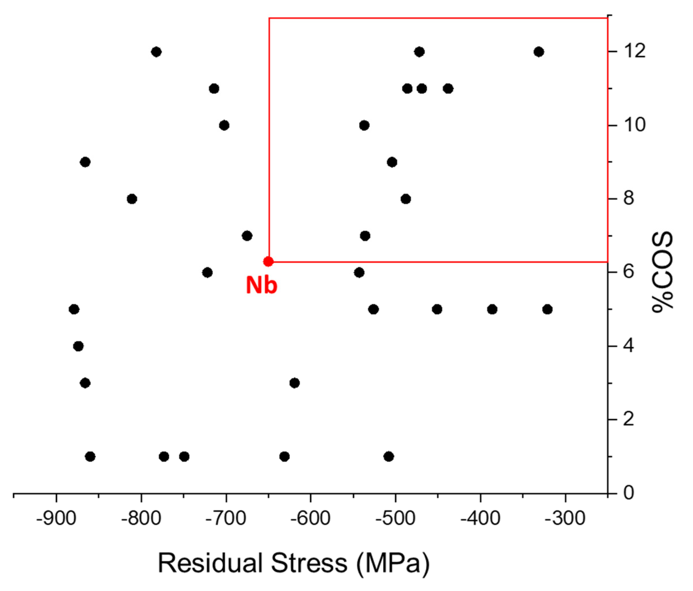
To illustrate, 30 random data points are generated with COS values between 1 and 12% and residual stresses between −900 and −300 MPa, each representing a distinct RHEA composition. Assume the objective is to identify alloys with greater intrinsic ductility than Nb. By plotting COS against residual stress, a target region can be defined (Figure 8), bounded by COS > 6.3% and −650 MPa < stress < −250 MPa. This range is chosen because Nb films exhibit an average residual stress of −650 MPa and COS of 6.3%, which serves as the relevant baseline for ductile behavior in this example scenario.
Our results indicate that compressive residual stress delays crack onset strain. As film stress becomes less compressive (or more tensile), the COS decreases for a material of comparable ductility. Thus, if a film exhibits a stress of −500 MPa but the same intrinsic ductility as Nb, its COS would be expected to fall below 6.3%. Accordingly, alloys that correspond to points lying in the upper-right boxed region of Figure 8, having both less compressive stress and higher COS than Nb, are predicted to exhibit higher levels of intrinsic ductility. This stress–COS framework offers an efficient pathway to screen large compositional spaces without the need for extensive bulk tensile testing. The effectiveness of this approach has been demonstrated in the well-studied VNbMoTaW RHEA system, where stress–COS-based ductility rankings were shown to correlate with ductility trends observed from indentation fractography of bulk samples [26].
This hypothetical scenario demonstrates how the proposed approach can aid in identifying alloys with enhanced intrinsic ductility, by screening compositions over a wide range of RHEA space. It serves as a theoretical framework for the potential application of the approach in guiding the design and screening of refractory alloys with improved mechanical properties.
Furthermore, the stress–COS plot described above can be used to rank metals and alloys based on their ‘relative ductility’. As demonstrated here, thin film fragmentation testing is significantly more feasible than traditional techniques for bulk materials, and therefore the speed and ease of dataset generation are improved. Such datasets could then be utilized for the development and training of machine learning models. A key advantage of machine learning approaches is their flexibility. They do not necessarily require precise ductility values—instead, a reliable ‘ductility trend’ with sufficient data points can serve as a valuable input for these models.

4. Conclusions

Our study demonstrates the utility of the in-situ fragmentation test as a tool for estimating the relative ductility of sputtered thin films of refractory metals such as W, Ta, Mo, and Nb. By controlling the relevant fabrication parameters, we have shown that these thin films can replicate the trends in ductility exhibited by their bulk counterparts. This qualitative screening procedure holds promise as a fast and cost-effective approach to obtaining valuable data for designing refractory high-entropy alloys with improved ductility, with the potential for significant reduction in the time needed for tensile testing of bulk candidate materials. To ensure consistency in reporting, a common framework should be established by the scientific community, specifying a standard combination of residual stress and film thickness for comparing values of crack onset strain (COS). The efficiency of this approach can be further enhanced by adopting high-throughput experiments. Filling the gap in generating tensile property data for RHEAs, this refined approach has the potential to significantly advance the design and development of these promising materials.

Supplementary Materials

The following supporting information can be downloaded at: https://www.mdpi.com/article/10.3390/met15101144/s1, Figure S1: XRD patterns of as-deposited W samples at varying thickness. All films were deposited at 3.5 mtorr. Figure S2: Experimental setup for fragmentation testing.

Author Contributions

Conceptualization, T.B.N.T. and T.J.B.; Methodology, T.B.N.T. and T.J.B.; Validation, T.B.N.T.; Formal analysis, T.B.N.T.; Investigation, T.B.N.T.; Resources, T.J.B.; Data curation, T.B.N.T.; Writing—original draft, T.B.N.T.; Writing—review and editing, T.B.N.T. and T.J.B.; Supervision, T.J.B.; Project administration, T.J.B.; Funding acquisition, T.J.B. All authors have read and agreed to the published version of the manuscript.

Funding

This work was supported by the U.S. Department of Energy, Office of Science, Basic Energy Sciences, under Award # DE-SC0019402.

Data Availability Statement

The raw data supporting the conclusions of this article will be made available by the authors on request.

Acknowledgments

During the preparation of this work the authors used ChatGPT in order to paraphrase and improve readability. After using this service, the authors reviewed and edited the content as needed and take full responsibility for the content of the publication. (OpenAI. ChatGPT (GPT-5) [Large language model]. https://chat.openai.com/ (last accessed: 1 October 2025)).

Conflicts of Interest

The authors declare no conflict of interest.

References

  1. Senkov, O.N.; Tsakiropoulos, P.; Couzinié, J.-P. Special Issue “Advanced Refractory Alloys”: Metals, MDPI. Metals 2022, 12, 333. [Google Scholar] [CrossRef]
  2. Soni, V.; Senkov, O.N.; Gwalani, B.; Miracle, D.B.; Banerjee, R. Microstructural Design for Improving Ductility of An Initially Brittle Refractory High Entropy Alloy. Sci. Rep. 2018, 8, 8816. [Google Scholar] [CrossRef] [PubMed]
  3. Qi, L.; Chrzan, D.C. Tuning Ideal Tensile Strengths and Intrinsic Ductility of bcc Refractory Alloys. Phys. Rev. Lett. 2014, 112, 115503. [Google Scholar] [CrossRef]
  4. Winter, I.S.; de Jong, M.; Montoya, J.; Rothchild, E.; Chrzan, D.C. Intrinsic ductility of random substitutional alloys from nonlinear elasticity theory. Phys. Rev. Mater. 2019, 3, 113608. [Google Scholar] [CrossRef]
  5. Raza, H.; Cheng, J.; Wang, J.; Kandasamy, S.; Zheng, G.; Chen, G. Titanium-containing high entropy oxide (Ti-HEO): A redox expediting electrocatalyst towards lithium polysulfides for high performance Li-S batteries. Nano Res. Energy 2024, 3, e9120116. [Google Scholar] [CrossRef]
  6. Qin, Y.; Du, Z.; Liu, X.; Yu, J. Research Progress of High Entropy Carbides. J. Wuhan Univ. Technol.-Mat. Sci. Ed. 2024, 39, 1440–1448. [Google Scholar] [CrossRef]
  7. Li, C.; Liu, Y.; Li, B.; Yuan, Z.; Yang, T.; Liu, Y.; Gao, H.; Xu, L.; Yu, X.; Luo, Q.; et al. Enhanced energy storage in high-entropy ferroelectric polymers. Nat. Mater. 2025, 24, 1066–1073. [Google Scholar] [CrossRef]
  8. Senkov, O.N.; Miracle, D.B.; Chaput, K.J.; Couzinie, J.-P. Development and exploration of refractory high entropy alloys—A review. J. Mater. Res. 2018, 33, 3092–3128. [Google Scholar] [CrossRef]
  9. Zhuo, L.; Xie, Y.; Chen, B. A review on recent progress of refractory high entropy alloys: From fundamental research to engineering applications. J. Mater. Res. Technol. 2024, 33, 1097–1129. [Google Scholar] [CrossRef]
  10. Hu, Y.-J.; Sundar, A.; Ogata, S.; Qi, L. Screening of generalized stacking fault energies, surface energies and intrinsic ductile potency of refractory multicomponent alloys. Acta Mater. 2021, 210, 116800. [Google Scholar] [CrossRef]
  11. Tandoc, C.; Hu, Y.-J.; Qi, L.; Liaw, P.K. Mining of lattice distortion, strength, and intrinsic ductility of refractory high entropy alloys. npj Comput. Mater. 2023, 9, 53. [Google Scholar] [CrossRef]
  12. Lee, C.; Xie, D.; Kyle Derby, B.; Kevin Baldwin, J.; Tandoc, C.; EI Atwani, O.; Hu, Y.-J.; Valdez, J.A.; Li, N.; Fensin, S.J. An experimentally driven high-throughput approach to design refractory high-entropy alloys. Mater. Des. 2022, 223, 111259. [Google Scholar] [CrossRef]
  13. Li, Z.; Ludwig, A.; Savan, A.; Springer, H.; Raabe, D. Combinatorial metallurgical synthesis and processing of high-entropy alloys. J. Mater. Res. 2018, 33, 3156–3169. [Google Scholar] [CrossRef]
  14. He, J.; Li, Z.; Lin, J.; Zhao, P.; Zhang, H.; Zhang, F.; Wang, L.; Cheng, X. Machine learning-assisted design of refractory high-entropy alloys with targeted yield strength and fracture strain. Mater. Des. 2024, 246, 113326. [Google Scholar] [CrossRef]
  15. Liu, X.; Zhang, J.; Pei, Z. Machine learning for high-entropy alloys: Progress, challenges and opportunities. Prog. Mater. Sci. 2023, 131, 101018. [Google Scholar] [CrossRef]
  16. Miracle, D.; Majumdar, B.; Wertz, K.; Gorsse, S. New strategies and tests to accelerate discovery and development of multi-principal element structural alloys. Scr. Mater. 2017, 127, 195–200. [Google Scholar] [CrossRef]
  17. Ribeiro, B.L.; Monclús, M.A.; Barbosa, M.; Torralba, J.M.; Malheiros, L.F.; Santos, R.F.; Sequeiros, E.W. High-throughput screening of MoNbTaW-based Refractory High-Entropy Alloys through Direct Energy Deposition in-situ alloying. Mater. Charact. 2024, 217, 114346. [Google Scholar] [CrossRef]
  18. Less Common Nonferrous Metals. In Materials Handbook: A Concise Desktop Reference; Cardarelli, F., Ed.; Springer: London, UK, 2008; pp. 213–454. ISBN 978-1-84628-669-8. [Google Scholar]
  19. Chen, Y.; Li, Y.; Cheng, X.; Wu, C.; Cheng, B.; Xu, Z. The Microstructure and Mechanical Properties of Refractory High-Entropy Alloys with High Plasticity. Materials 2018, 11, 208. [Google Scholar] [CrossRef]
  20. Chen, B.; Zhuo, L. Latest progress on refractory high entropy alloys: Composition, fabrication, post processing, performance, simulation and prospect. Int. J. Refract. Met. Hard Mater. 2023, 110, 105993. [Google Scholar] [CrossRef]
  21. Baëtens, T.; Pallecchi, E.; Thomy, V.; Arscott, S. Cracking effects in squashable and stretchable thin metal films on PDMS for flexible microsystems and electronics. Sci. Rep. 2018, 8, 9492. [Google Scholar] [CrossRef]
  22. Chen, X.; Kirsch, B.L.; Senter, R.; Tolbert, S.H.; Gupta, V. Tensile testing of thin films supported on compliant substrates. Mech. Mater. 2009, 41, 839–848. [Google Scholar] [CrossRef]
  23. Cordill, M.J.; Glushko, O.; Kreith, J.; Marx, V.M.; Kirchlechner, C. Measuring electro-mechanical properties of thin films on polymer substrates. Microelectron. Eng. 2015, 137, 96–100. [Google Scholar] [CrossRef] [PubMed]
  24. Jörg, T.; Music, D.; Hauser, F.; Cordill, M.J.; Franz, R.; Köstenbauer, H.; Winkler, J.; Schneider, J.M.; Mitterer, C. Deformation behavior of Re alloyed Mo thin films on flexible substrates: In situ fragmentation analysis supported by first-principles calculations. Sci. Rep. 2017, 7, 7374. [Google Scholar] [CrossRef]
  25. Xia, A.; Dedoncker, R.; Glushko, O.; Cordill, M.J.; Depla, D.; Franz, R. Influence of the nitrogen content on the structure and properties of MoNbTaVW high entropy alloy thin films. J. Alloys Compd. 2021, 850, 156740. [Google Scholar] [CrossRef]
  26. Tuhser, T.B.N.; Winter, I.S.; Chrzan, D.; Balk, T.J. Enhancing intrinsic ductility in VNbMoTaW high entropy alloy: A combinatorial investigation with experimental evaluation of theoretical predictions. J. Mater. Res. Technol. 2025, 35, 3645–3654. [Google Scholar] [CrossRef]
  27. Xia, A.; Glushko, O.; Cordill, M.J.; Franz, R. Electromechanical properties of cathodic arc deposited high entropy alloy thin films on polymer substrates. J. Vac. Sci. Technol. A 2018, 37, 010601. [Google Scholar] [CrossRef]
  28. ASTM Standard D638-14; Standard Test Method for Tensile Properties of Plastics. ASTM International: West Conshohocken, PA, USA, 2022. [CrossRef]
  29. Glushko, O.; Cordill, M.J. Electrical Resistance of Metal Films on Polymer Substrates Under Tension. Exp. Tech. 2016, 40, 303–310. [Google Scholar] [CrossRef]
  30. Cordill, M.J.; Kreiml, P.; Mitterer, C. Materials Engineering for Flexible Metallic Thin Film Applications. Materials 2022, 15, 926. [Google Scholar] [CrossRef]
  31. Cordill, M.J.; Glushko, O.; Putz, B. Electro-Mechanical Testing of Conductive Materials Used in Flexible Electronics. Front. Mater. 2016, 3, 11. [Google Scholar] [CrossRef]
  32. Zhou, J.; Zhang, X.; Zhang, X.; Zhang, W.; Li, J.; Chen, Y.; Liu, H.; Yan, Y. Mechanical Properties of Tensile Cracking in Indium Tin Oxide Films on Polycarbonate Substrates. Coatings 2022, 12, 538. [Google Scholar] [CrossRef]
  33. Lu, N.; Wang, X.; Suo, Z.; Vlassak, J. Metal films on polymer substrates stretched beyond 50%. Appl. Phys. Lett. 2007, 91, 221909. [Google Scholar] [CrossRef]
  34. Leterrier, Y.; Médico, L.; Demarco, F.; Månson, J.-A.E.; Betz, U.; Escolà, M.F.; Kharrazi Olsson, M.; Atamny, F. Mechanical integrity of transparent conductive oxide films for flexible polymer-based displays. Thin Solid Films 2004, 460, 156–166. [Google Scholar] [CrossRef]
  35. Jörg, T.; Cordill, M.J.; Franz, R.; Glushko, O.; Winkler, J.; Mitterer, C. The electro-mechanical behavior of sputter-deposited Mo thin films on flexible substrates. Thin Solid Films 2016, 606, 45–50. [Google Scholar] [CrossRef]
  36. Kreiml, P.; Rausch, M.; Terziyska, V.L.; Köstenbauer, H.; Winkler, J.; Mitterer, C.; Cordill, M.J. Balancing the electro-mechanical and interfacial performance of Mo-based alloy films. Materialia 2020, 12, 100774. [Google Scholar] [CrossRef]
  37. Akbari, A. Combinatorial Screening Approach in Developing Non-Equiatomic High Entropy Alloys. Ph.D. Thesis, University of Kentucky Libraries, Lexington, KY, USA, 2018. [Google Scholar]
  38. Chen, S.; Wang, J.; Wu, R.; Wang, Z.; Li, Y.; Lu, Y.; Zhou, W.; Hu, P.; Li, H. Insights into the nucleation, grain growth and phase transformation behaviours of sputtered metastable β-W films. J. Mater. Sci. Technol. 2021, 90, 66–75. [Google Scholar] [CrossRef]
  39. Shen, Y.G.; Mai, Y.W.; Zhang, Q.C.; McKenzie, D.R.; McFall, W.D.; McBride, W.E. Residual stress, microstructure, and structure of tungsten thin films deposited by magnetron sputtering. J. Appl. Phys. 2000, 87, 177–187. [Google Scholar] [CrossRef]
  40. Sun, H.L.; Song, Z.X.; Guo, D.G.; Ma, F.; Xu, K.W. Microstructure and Mechanical Properties of Nanocrystalline Tungsten Thin Films. J. Mater. Sci. Technol. 2010, 26, 87–92. [Google Scholar] [CrossRef]
  41. Rossnagel, S.M.; Noyan, I.C.; Cabral, C. Phase transformation of thin sputter-deposited tungsten films at room temperature. J. Vac. Sci. Technol. B 2002, 20, 2047. [Google Scholar] [CrossRef]
  42. Vink, T.J.; Walrave, W.; Daams, J.L.C.; Dirks, A.G.; Somers, M.A.J.; van den Aker, K.J.A. Stress, strain, and microstructure in thin tungsten films deposited by dc magnetron sputtering. J. Appl. Phys. 1993, 74, 988–995. [Google Scholar] [CrossRef]
  43. Li, H.; Gao, D.; Xie, S.; Zou, J. Effect of magnetron sputtering parameters and stress state of W film precursors on WSe 2 layer texture by rapid selenization. Sci. Rep. 2016, 6, 36451. [Google Scholar] [CrossRef]
  44. Alfonso, J.A.; Greaves, E.D.; Lavelle, B.; Sajo-Bohus, L. Effect of sputtering pressure on residual stress in Ni films using energy-dispersive x-ray diffraction. J. Vac. Sci. Technol. A 2003, 21, 846–850. [Google Scholar] [CrossRef]
  45. El Khakani, M.A.; Chaker, M.; Le Drogoff, B. Iridium thin films deposited by radio-frequency magnetron sputtering. J. Vac. Sci. Technol. A 1998, 16, 885–888. [Google Scholar] [CrossRef]
  46. Vüllers, F.T.N.; Spolenak, R. Alpha- vs. beta-W nanocrystalline thin films: A comprehensive study of sputter parameters and resulting materials’ properties. Thin Solid Films 2015, 577, 26–34. [Google Scholar] [CrossRef]
  47. Djaziri, S.; Renault, P.-O.; Le Bourhis, E.; Goudeau, P.; Faurie, D.; Geandier, G.; Mocuta, C.; Thiaudière, D. Comparative study of the mechanical properties of nanostructured thin films on stretchable substrates. J. Appl. Phys. 2014, 116, 093504. [Google Scholar] [CrossRef]
  48. Tuhser, T.B.N. Advancing Combinatorial Screening of Refractory High Entropy Alloys Through Intrinsic Ductility Assessment via Thin Film Fragmentation Testing. Ph.D. Thesis, University of Kentucky, Lexington, KY, USA, 2024. [Google Scholar] [CrossRef]
  49. Choi, D.; Wang, B.; Chung, S.; Liu, X.; Darbal, A.; Wise, A.; Nuhfer, N.T.; Barmak, K.; Warren, A.P.; Coffey, K.R.; et al. Phase, grain structure, stress, and resistivity of sputter-deposited tungsten films. J. Vac. Sci. Technol. A 2011, 29, 051512. [Google Scholar] [CrossRef]
  50. Hofer, A.M.; Schlacher, J.; Keckes, J.; Winkler, J.; Mitterer, C. Sputtered molybdenum films: Structure and property evolution with film thickness. Vacuum 2014, 99, 149–152. [Google Scholar] [CrossRef]
  51. Cordill, M.J.; Taylor, A.A.; Schmidegg, K. Thickness Effects on the Fracture of Chromium Films on Polyethylene Terephthalate. BHM Berg- Hüttenmänn. Monatsh. 2011, 156, 434–437. [Google Scholar] [CrossRef]
  52. Colin, J.J.; Abadias, G.; Michel, A.; Jaouen, C. On the origin of the metastable β-Ta phase stabilization in tantalum sputtered thin films. Acta Mater. 2017, 126, 481–493. [Google Scholar] [CrossRef]
  53. Chen, W.-C.; Wang, Z.-Y.; Yu, C.-Y.; Liao, B.-H.; Lin, M.-T. A study of the phase transformation of low temperature deposited tantalum thin films using high power impulse magnetron sputtering and pulsed DC magnetron sputtering. Surf. Coat. Technol. 2022, 436, 128288. [Google Scholar] [CrossRef]
  54. Al-masha’al, A.; Bunting, A.; Cheung, R. Evaluation of residual stress in sputtered tantalum thin-film. Appl. Surf. Sci. 2016, 371, 571–575. [Google Scholar] [CrossRef]
  55. Zhang, J.; Huai, Y.; Chen, L.; Zhang, J. Formation of low resistivity alpha Ta by ion beam sputtering. J. Vac. Sci. Technol. B 2003, 21, 237. [Google Scholar] [CrossRef]
  56. Kittel, C. Introduction to Solid State Physics, 8th ed.; Wiley: Hoboken, NJ, USA, 2005; Available online: https://www.wiley.com/en-us/Introduction+to+Solid+State+Physics%2C+8th+Edition-p-9780471415268 (accessed on 13 December 2020).
  57. Ni, Z.; Zhong, Y.; Tao, X.; Li, W.; Gao, H.; Yao, Y. Effects of Radio Frequency Bias on the Structure Parameters and Mechanical Properties of Magnetron-Sputtered Nb Films. Crystals 2022, 12, 256. [Google Scholar] [CrossRef]
  58. Yang, Z.-H.; Wu, P.-C.; Chuang, T.-H. Effects of substrate bias on the sputtering of high density (111)-nanotwinned Cu films on SiC chips. Sci. Rep. 2022, 12, 15408. [Google Scholar] [CrossRef] [PubMed]
  59. Frank, S.; Gruber, P.A.; Handge, U.A.; Spolenak, R. In situ studies on the cohesive properties of α- and β-Ta layers on polyimide substrates. Acta Mater. 2011, 59, 5881–5892. [Google Scholar] [CrossRef]
  60. Xiang, Y.; Li, T.; Suo, Z.; Vlassak, J.J. High ductility of a metal film adherent on a polymer substrate. Appl. Phys. Lett. 2005, 87, 161910. [Google Scholar] [CrossRef]
  61. Li, C.H.; Dedoncker, R.; Li, L.W.; Sedghgooya, F.; Zighem, F.; Ji, V.; Depla, D.; Djemia, P.; Faurie, D. Mechanical properties of CoCrCuFeNi multi-principal element alloy thin films on Kapton substrates. Surf. Coat. Technol. 2020, 402, 126474. [Google Scholar] [CrossRef]
  62. Tian, B.; Yu, Q.; Zhang, Z.; Du, Z.; Ren, W.; Shi, P.; Jiang, Z. Effect of magnetron sputtering parameters on adhesion properties of tungsten-rhenium thin film thermocouples. Ceram. Int. 2018, 44, S15–S18. [Google Scholar] [CrossRef]
  63. Tanaka, K.; Stossel, M.; Jiang, H.; Arola, D.; Wang, J. Engineering the Interface: Effects of Interfacial Adhesion and Substrate Thickness on the Ductility of Polymer-supported Metal Films. Exp. Mech. 2022, 62, 49–58. [Google Scholar] [CrossRef]
  64. Xi, Y.; Gao, K.; Pang, X.; Yang, H.; Xiong, X.; Li, H.; Volinsky, A.A. Film thickness effect on texture and residual stress sign transition in sputtered TiN thin films. Ceram. Int. 2017, 43, 11992–11997. [Google Scholar] [CrossRef]
  65. Pradeep, K.G.; Tasan, C.C.; Yao, M.J.; Deng, Y.; Springer, H.; Raabe, D. Non-equiatomic high entropy alloys: Approach towards rapid alloy screening and property-oriented design. Mater. Sci. Eng. A 2015, 648, 183–192. [Google Scholar] [CrossRef]
  66. Wilson, P.; Field, R.; Kaufman, M. The use of diffusion multiples to examine the compositional dependence of phase stability and hardness of the Co-Cr-Fe-Mn-Ni high entropy alloy system. Intermetallics 2016, 75, 15–24. [Google Scholar] [CrossRef]
  67. Balar, N.; O’Connor, B.T. Correlating Crack Onset Strain and Cohesive Fracture Energy in Polymer Semiconductor Films. Macromolecules 2017, 50, 8611–8618. [Google Scholar] [CrossRef]
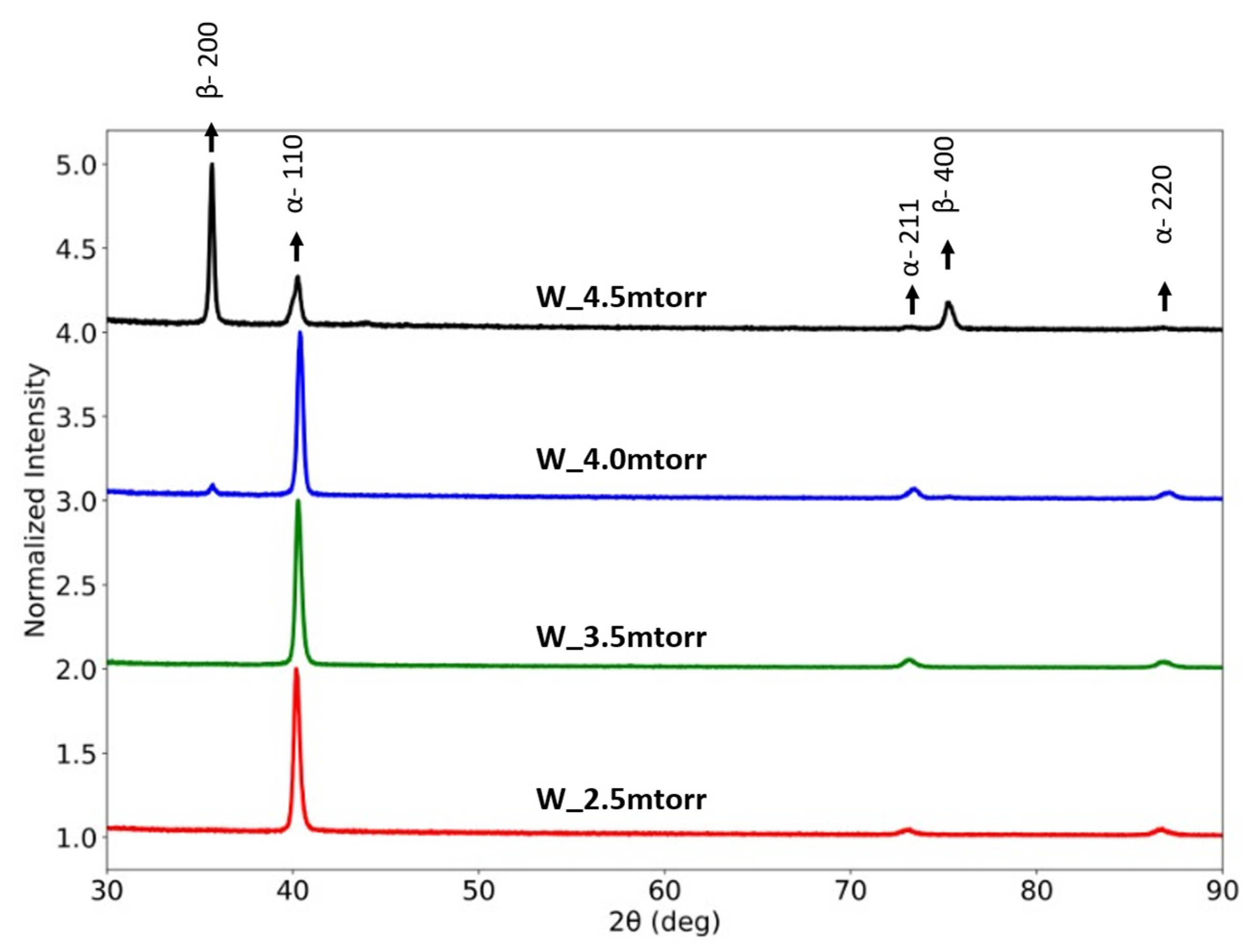
Figure 1. XRD patterns of as-deposited W samples at varying sputtering pressures. All films are 180 nm thick. The β phase was observed for thin films sputtered at 4.0 mtorr or higher pressure.
Metals 15 01144 g001
Figure 2. Variations in residual stress and R0 for 180 nm thick W films deposited under different Ar sputtering pressures. The lines displayed in the graph are provided solely for visual guidance.
Metals 15 01144 g002
Figure 3. (a) In-situ test results showing the resistance of W films sputtered under different Ar pressures. COS increases with decreasing chamber pressure, due to compressive residual film stress that results from lower Ar sputtering pressure. The ‘Theory’ line represents Equation (1), and the ‘1.1 * theory’ line represents the COS criterion of 10% deviation from Equation (1). (b) Crack pattern in W_3.5mtorr at Δl/l0 = 0.2. The load axis is horizontal in this image. Similar patterns of parallel crack lines (all perpendicular to the load axis) were observed for other films.
Metals 15 01144 g003
Figure 4. Effect of thickness on residual stress and R0 of W films. All films exhibited a single-phase BCC structure. The lines displayed in the graph are provided solely for visual guidance.
Metals 15 01144 g004
Figure 5. In-situ resistance measurements during tensile testing, showing the COS values for W films of different thickness. The ‘Theory’ line represents Equation (1).
Metals 15 01144 g005
Figure 6. XRD patterns of as-deposited refractory thin films on Kapton substrates. W, Mo and Nb exhibit a single-phase BCC structure with strong {110} texture. Ta exhibits a mixed-phase microstructure of α and metastable β.
Metals 15 01144 g006
Figure 7. Comparison of in-situ resistance plots for W, Ta, Mo and Nb. All films are 180 nm thick and have a compressive stress of approximately −650 MPa. The ‘Theory’ line represents Equation (1).
Metals 15 01144 g007
Figure 8. A hypothetical plot showing utilization of in-situ fragmentation testing for screening COS samples to identify intrinsically ductile alloy compositions. Here, a Nb sample is used as the benchmark. The rectangular box indicates compositions that should exhibit elevated ductility compared to Nb.
Metals 15 01144 g008
Table 1. Process variables relevant to thin film deposition, as well as the resultant film stress, R0, COS, and crystallite size of as-deposited W samples.
Material IDPressure
(mtorr)
Thickness
(nm)
Stress
(MPa)
R0
(Ω)
COS
(Δl/l0 × 100) %
Crystallite Size
(nm)
W_2.5mtorr2.5 (0.33 Pa)180−1304 ± 355.682.7025
W_3.5mtorr/
W_180nm *
3.5 (0.47 Pa)180−670 ± 205.042.2026
W_4.0mtorr4.0 (0.53 Pa)180−360 ± 1316.90.7227
W_4.5mtorr4.5 (0.60 Pa)180211 ± 12~550.6618 (α)
42 (β)
W_300nm3.5 (0.47 Pa)300−1024 ± 143.721.8733
W_400nm3.5 (0.47 Pa)400−1055 ± 292.11.6929
* W_180nm is used for thickness variation study.
Table 2. Film deposition parameters and the resultant stress, phase (crystal structure), R0, crystallite size, and COS of as-deposited films of pure refractory metals W, Ta, Mo and Nb.
MaterialPressure
(mtorr)
Thickness
(nm)
Stress
(MPa)
PhaseCrystallite Size
(nm)
COS
(Δl/l0 × 100) %
R0
(Ω)
Bulk Resistivity **
(×10−8 Ω-m)
W3.5 (0.47 Pa)180−670 ± 20α262.205.045.3
Ta3.5 (0.47 Pa)180−641 ± 7α + β30(β)2.6333.7513.1
Mo *2.5 (0.33 Pa)180−677 ± 22α241.616.305.3
Nb1.8 (0.24 Pa)180−650 ± 32α176.378.7714.5
* Mo was deposited with 10 W bias in order to achieve a comparable film stress. ** The values of bulk resistivity were taken from reference [56] for comparison.
Disclaimer/Publisher’s Note: The statements, opinions and data contained in all publications are solely those of the individual author(s) and contributor(s) and not of MDPI and/or the editor(s). MDPI and/or the editor(s) disclaim responsibility for any injury to people or property resulting from any ideas, methods, instructions or products referred to in the content.