1. Introduction
Secondary cooling is a crucial stage that directly influences slab quality and has therefore been extensively studied worldwide. To ensure high slab quality, it is generally desirable for the slab to undergo uniform cooling in the secondary cooling zone. Insufficient uniformity often leads to defects such as cracks and segregation [
1,
2,
3,
4,
5]. However, uniform cooling is not a one-dimensional process but is affected by multiple factors in different directions. For example, cooling must be considered along both the casting direction and slab width [
6,
7,
8,
9]. Poor uniformity in the width direction can readily cause corner cracks [
10,
11], whereas inadequate uniformity in the thickness and casting directions may allow surface cracks to propagate into internal cracks [
12,
13,
14]. These challenges impose stringent requirements on heat transfer during solidification in secondary cooling, thereby necessitating a multi-dimensional approach to ensure uniform cooling and high-quality slabs.
In recent years, several scholars have investigated slab uniform cooling from different dimensional perspectives. Along the slab width direction, Yanyan Bi et al. [
15] analyzed the surface temperature distribution of round billets in the secondary cooling zone and proposed a new nozzle arrangement, thereby eliminating the adverse effects of nonuniform surface temperature on slab quality. Similarly, C. Ji et al. [
16] constructed a solidification heat transfer model for wide-thick slabs, optimized the nozzle layout, and demonstrated that the improved spray pattern reduced corner crack defects. To ensure slab surface temperatures remain above the brittle range during straightening, Y. J. Lu et al. [
3] optimized the secondary cooling system by adopting an asymmetric nozzle arrangement, which significantly lowered the incidence of corner cracks. Min Jiang et al. [
17] redistributed the water flow among transverse nozzles by reducing flow from central nozzles and increasing flow from edge nozzles, enabling synchronous solidification, enhancing the soft reduction effect, and reducing porosity defects. In addition, Yanshen Han [
18] optimized nozzle arrangement to improve transverse water flow distribution, thereby increasing corner temperature, ensuring more uniform cooling across the slab width, and enhancing corner quality.
From the casting direction, Qiang Liu et al. [
19] investigated secondary cooling water distribution in beam blanks, focusing on the effects of specific water flow, water Flow Rate in Each Secondary Cooling Zone, and inner-to-outer arc water ratios on the slab temperature field. Hongming Wang et al. [
20] showed that directly reducing cooling water in each secondary cooling zone, as well as shutting down or lowering water flow at the zone end, effectively increased slab surface temperature. This not only improved slab quality but also enabled hot-slab continuous casting–rolling production. Josef Stetina et al. [
21] demonstrated that replacing large-flow nozzles with smaller ones reduced nozzle flow while maintaining cooling intensity, thereby increasing slab surface temperature at the straightening point and ensuring product quality. Xiaogang Yang et al. [
22] applied a similar approach by reducing water flow in selected zones, which raised surface temperature at the straightening point. Industrial trials confirmed that this optimization effectively decreased the incidence of corner cracks. Jingbo Yang et al. [
10] further optimized water distribution in certain zones to control slab surface temperature in the straightening region, which refined overall grain size uniformity, improved corner ductility, and enhanced corner quality.
Nevertheless, comprehensive studies on multi-dimensional uniform cooling of slabs in the secondary cooling zone remain limited. Most existing research has focused on single-dimensional effects, without fully considering the combined influence of different cooling directions on slab surface temperature.
In this study, a slab continuous caster from a steel plant was selected as the research object, and a two-dimensional solidification heat transfer model was developed using the finite difference method. Through numerical simulations, the solidification heat transfer process of ship plate steel was investigated from multiple dimensional perspectives, leading to the development of a secondary cooling model. This model ensures uniform cooling along the slab width, thickness, and casting directions, effectively controls surface temperature, and thereby guarantees slab quality.
4. Simulation Analysis of Multi-Dimensional Uniform Cooling Process
The secondary cooling model used in this study is a static control model, in which the water flow in each circuit of the secondary cooling zones follows a quadratic relationship with the casting speed. This model is also widely employed in many industrial applications [
33].
where
Qi is the water flow rate in the
i-th secondary cooling circuit (L/min);
v is the casting speed (m/min);
ai,
bi,
ci are constant parameters; and
Ki is a coefficient, generally ranging from 0.9 to 1.1, with a default value of 1.0.
By considering the slab’s uniform cooling from multiple dimensions during the secondary cooling process, heat transfer simulations of the continuous casting process were performed to determine the water flow rates in each secondary cooling zone. Using the method of least squares, the relationship between water flow in each circuit and casting speed was fitted to determine the parameters ai, bi, ci. The multi-dimensional analysis of uniform cooling in the secondary cooling zones resulted in a model capable of ensuring high slab quality.
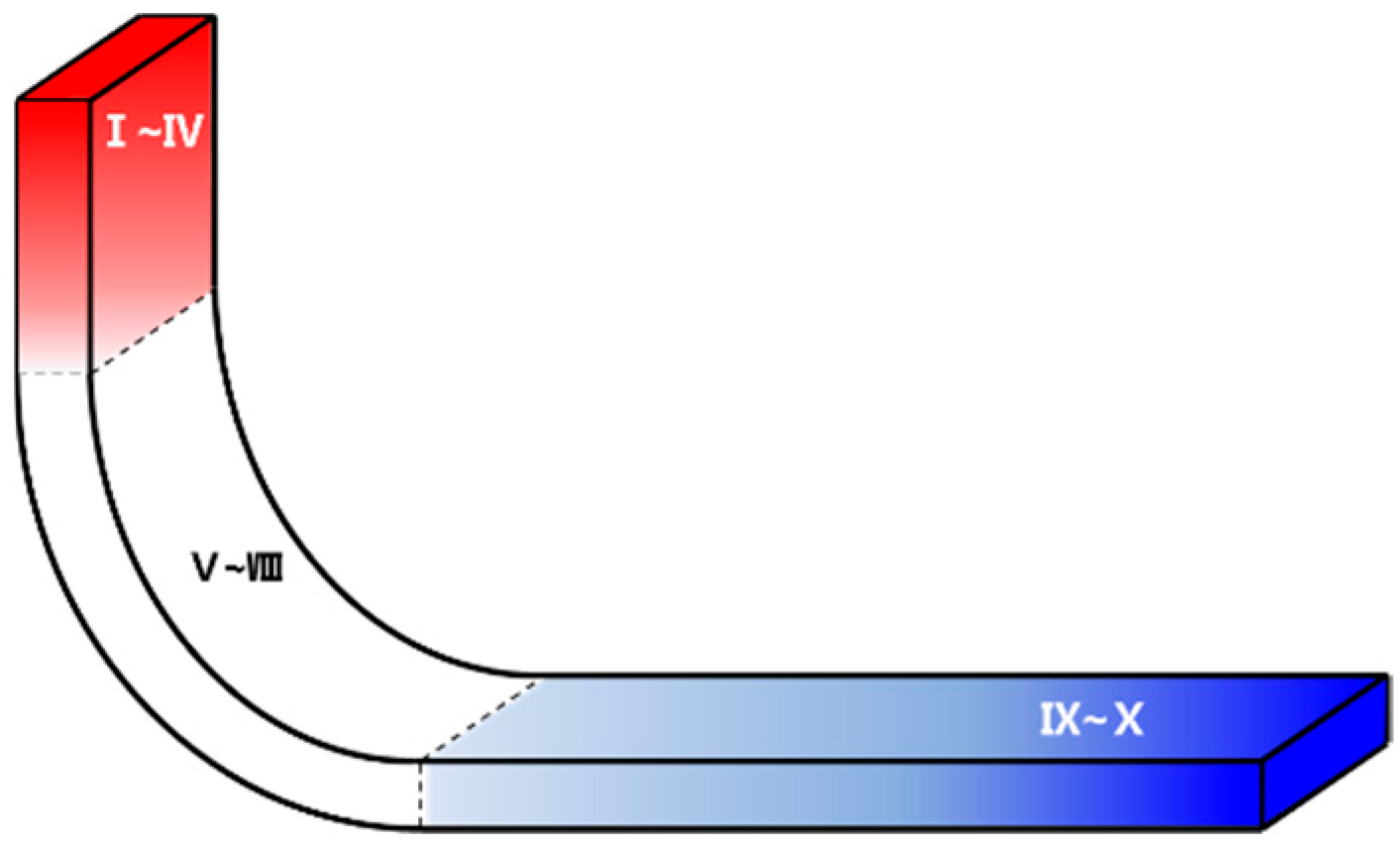
The simulation of the multi-dimensional uniform cooling process was carried out through the following five aspects: (1) the water-to-slab ratio in secondary cooling; (2) variation curves of cooling water flow in each secondary cooling zone with casting speed; (3) the ratio of inner-arc to outer-arc cooling water; (4) the distribution of cooling water along the casting direction; and (5) the shutdown strategy of cooling water at medium and low casting speeds.
Simulations were conducted using Q235B steel with a superheat of 25 °C and a slab cross-section of 1820 × 230 mm at casting speeds of 0.8, 1.2, 1.6, and 2.0 m/min. The resulting water flow model is applicable for casting speeds in the range of 0.8–2.0 m/min.
4.2. Cooling Heat Transfer in the Casting Direction
According to metallurgical criteria, the slab surface center temperature along the casting direction must remain stable, with temperature fluctuations minimized. To ensure slab quality, the maximum surface cooling rate is strictly limited to below 100 °C/m, guaranteeing uniform solidification and preventing internal cracks or surface defects caused by sudden temperature changes.
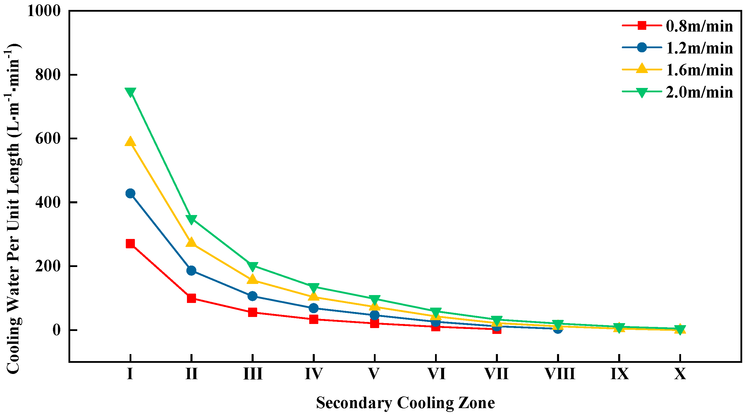
In secondary cooling zones 1 and 2, the slab shell is relatively thin upon exiting the mold, requiring higher cooling intensity to avoid steel leakage. Therefore, larger water flows are applied in zones 1 and 2. During the secondary cooling process, the slab shell gradually thickens along the casting direction. If the cooling intensity in each zone does not gradually decrease along this direction, a large internal temperature gradient may develop, adversely affecting slab quality. To prevent the slab surface temperature from entering the brittle range in the straightening zone, the distribution of cooling water in each secondary cooling zone must be carefully regulated. The cooling intensity in the secondary cooling zones can be represented by the water flow per unit length along the inner arc (i.e., the inner-arc water flow divided by the zone length).
The water flow per unit length in each secondary cooling zone is shown in
Figure 3.
From
Figure 3, it can be seen that for all four casting speeds, the inner-arc water flow per unit length in the secondary cooling zones gradually decreases along the casting direction.
Table 6 lists the average inner-arc surface center temperatures of the slab in each secondary cooling zone, as well as the slab surface temperatures at the straightening start point, for the different casting speeds.
From
Table 6, it can be seen that the inner-arc surface center temperature of the slab at the straightening point is well above 900 °C. This high surface temperature helps the slab avoid the brittle range, ensuring slab quality.
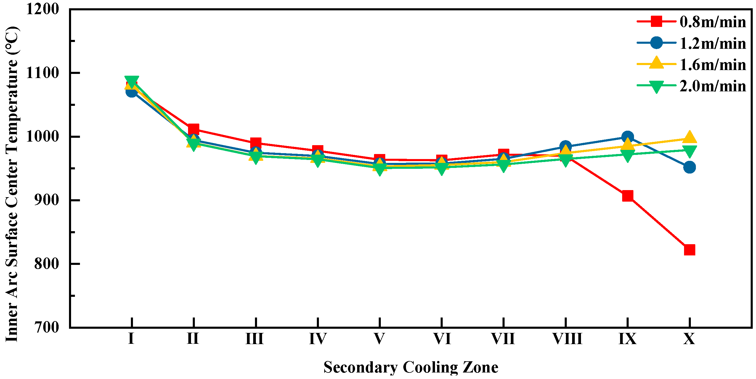
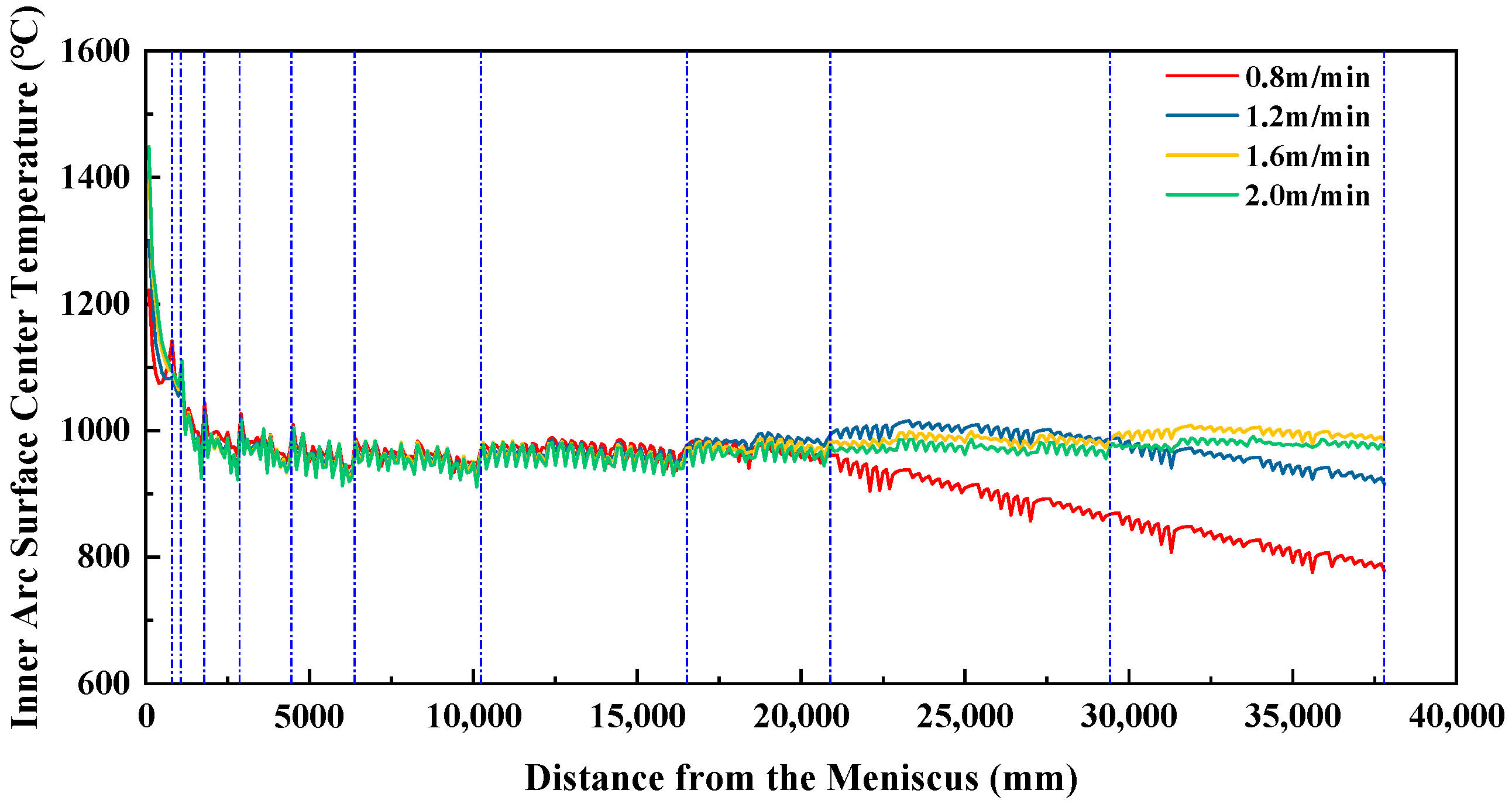
The variation curves of the average inner-arc surface center temperatures along the casting direction for each secondary cooling zone at different casting speeds are shown in
Figure 4, while the inner-arc surface center temperature profiles along the casting direction for different casting speeds are presented in
Figure 5.
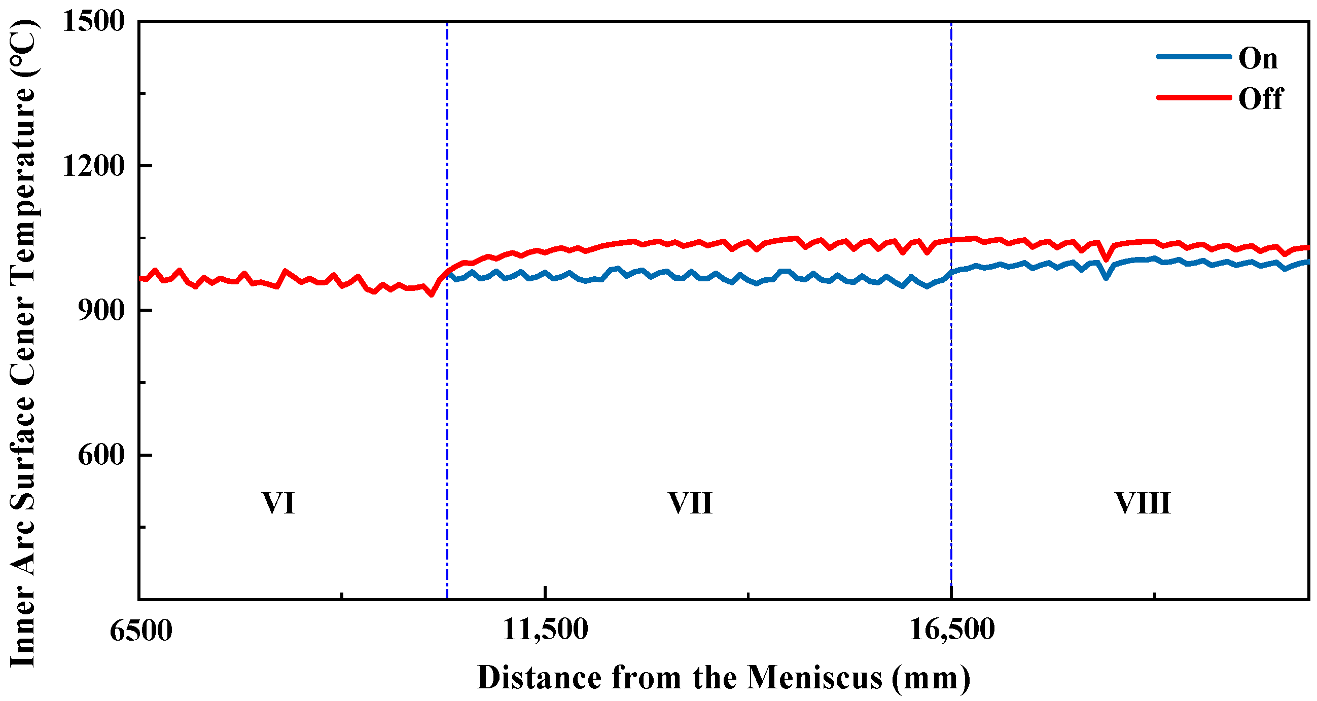
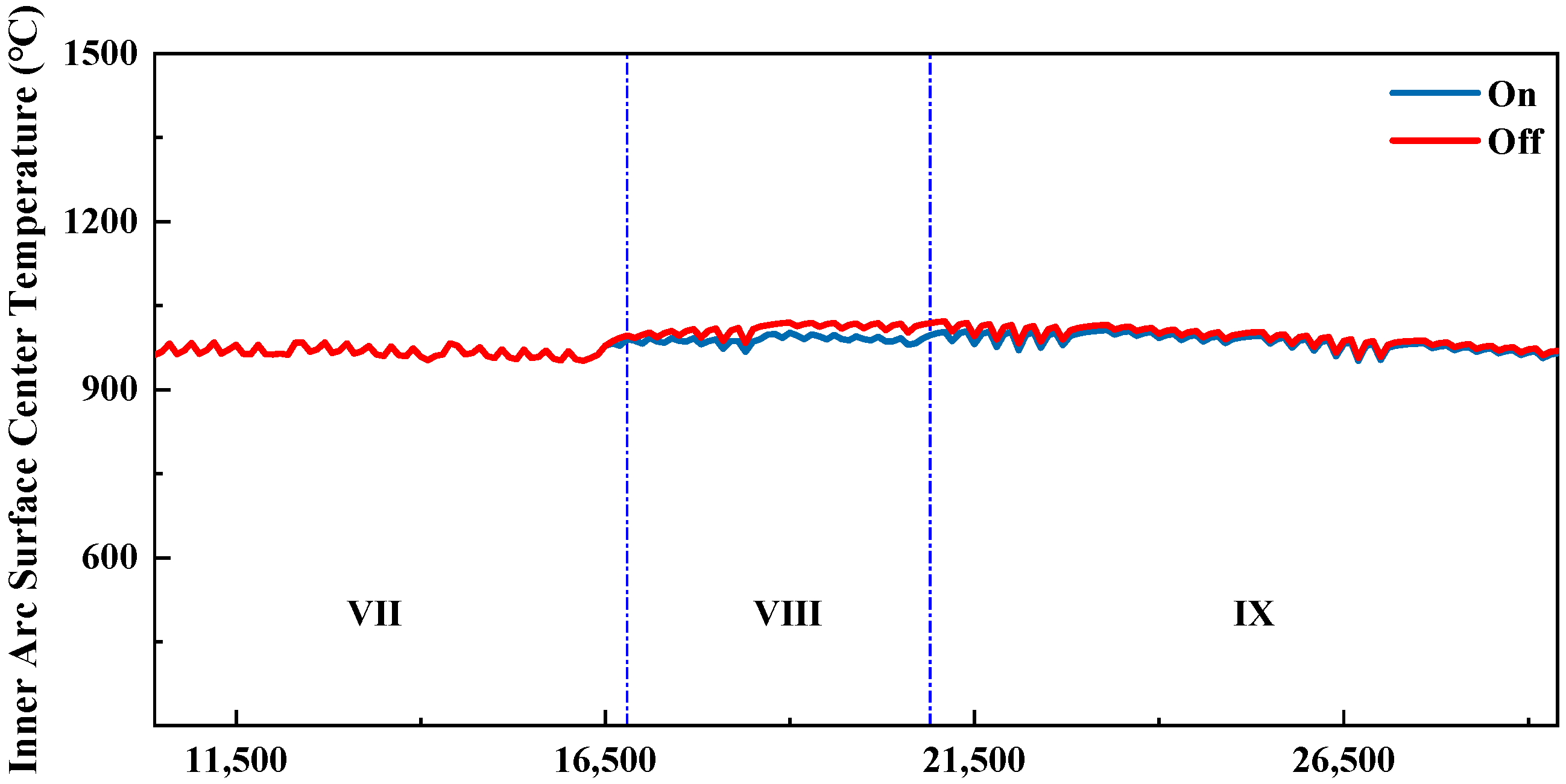
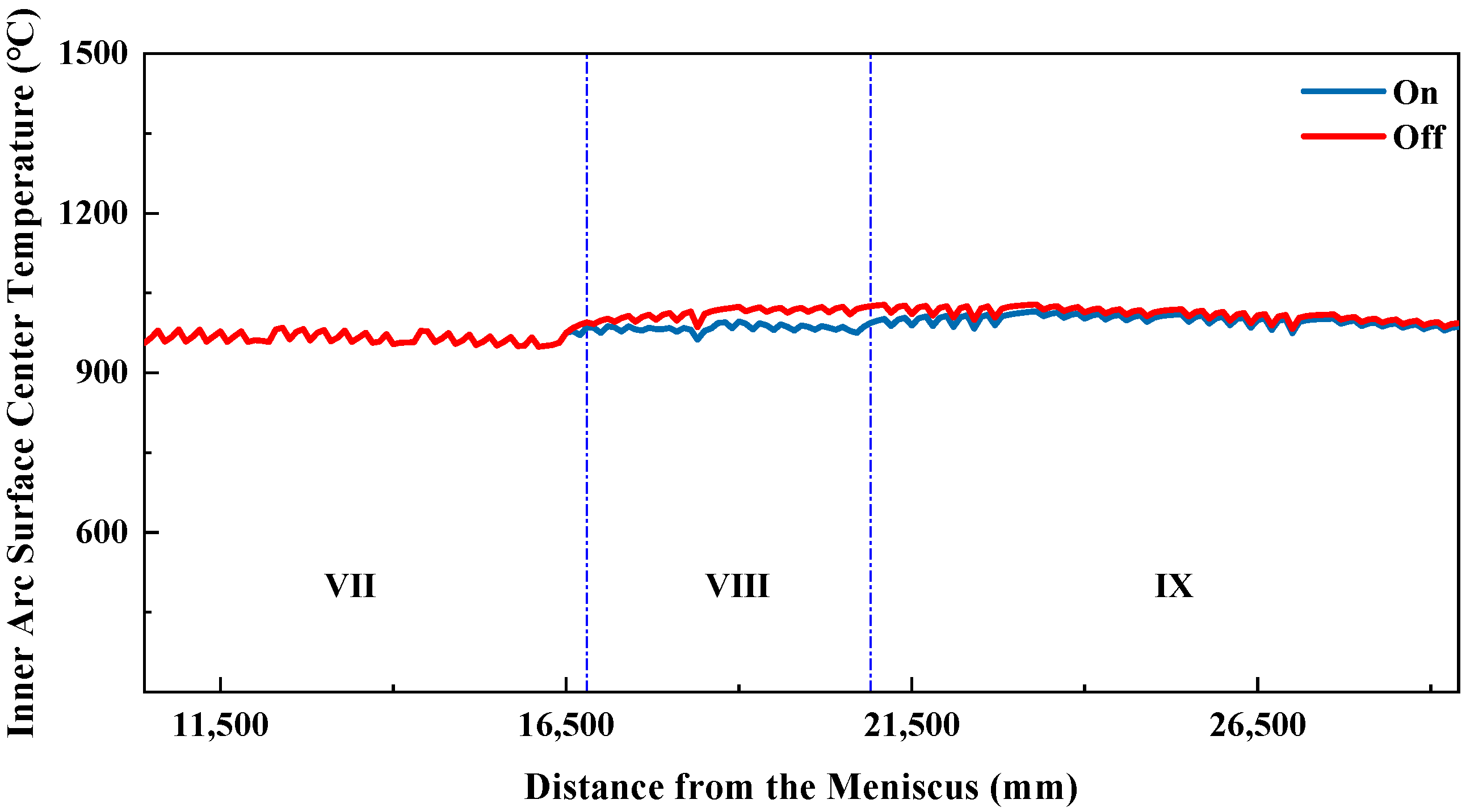
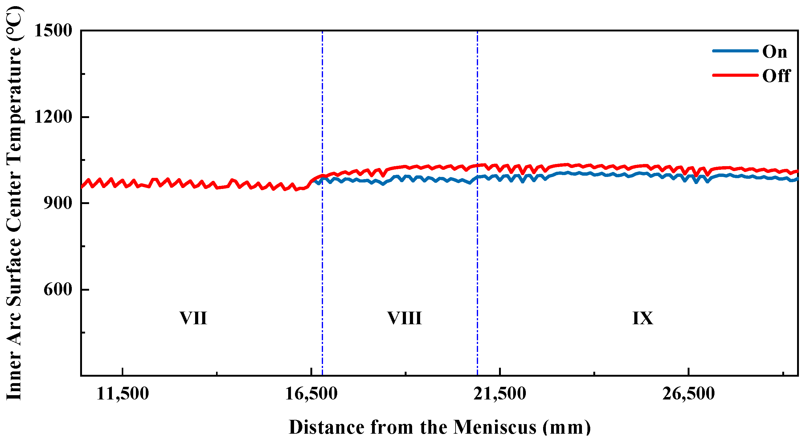
From the above two figures, it can be observed that the cooling rates in each zone conform to the design principles of secondary cooling. In the initial stage of secondary cooling, the inner-arc surface center temperature of the slab drops rapidly, preventing shell breakage. Subsequently, the slab surface temperature decreases more slowly as the shell gradually thickens. In secondary cooling zones 6 to 8, a slight temperature rebound is observed, which helps ensure that the slab surface temperature at the straightening point avoids the low-ductility range.
In secondary cooling zones 9 and 10, there is a significant difference in the inner-arc surface center temperature of the slab at different casting speeds. This is because the solidification endpoint varies with casting speed: at lower speeds, the slab solidifies earlier, releasing latent heat sooner, which results in a lower surface temperature in the later stages of secondary cooling.
4.3. Analysis of Inner-Arc and Outer-Arc Cooling Differences
During slab production on a straight-arc continuous casting machine, the heat transfer efficiency differs between the inner and outer arcs of the slab in the curved sections, primarily in the water pooling and evaporation heat transfer from the spray water. On the inner arc, the spray water flows along the slab surface and accumulates at the contact interface with the guide rolls, resulting in more water pooling and evaporation heat transfer. On the outer arc, however, gravity causes the sprayed water to fall immediately after contacting the slab surface, preventing accumulation and thus providing little or no water pooling and evaporation heat transfer.
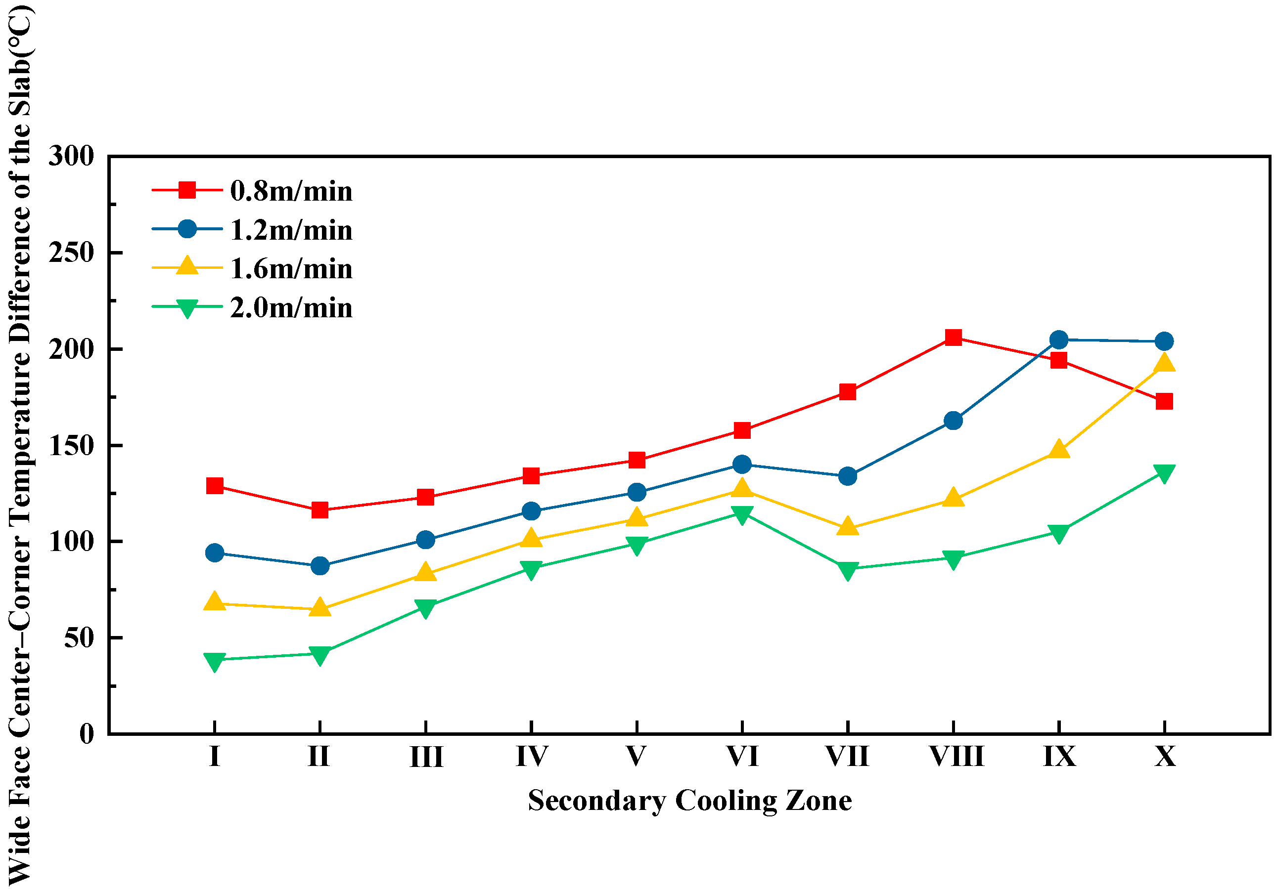
This process is complex; therefore, in establishing the mathematical model for simulation, this difference in heat transfer was not considered, and the inner and outer arcs were assumed to have the same heat transfer efficiency in this aspect. As a result, the simulated temperature difference between the inner and outer arcs is larger than the actual difference. To address this, the inner-to-outer arc water flow ratio was adjusted to maintain the temperature difference within 20 °C.
Since the temperature difference between inner and outer arcs increases with casting speed, this study focuses on a casting speed of 2.0 m/min. The inner-to-outer arc water flow ratio is defined as the inner-arc water flow divided by the outer-arc water flow.
Based on the basic structure of the caster, secondary cooling zones 1 to 4 are vertical sections where the heat transfer efficiency of the inner and outer arcs is similar. In these zones, the inner and outer arc water flows are set equal, i.e., the inner-to-outer arc water flow ratio is 1. When the slab enters the curved section in secondary cooling zone 5, the heat transfer efficiency of the inner and outer arcs begins to differ. Because the inner arc has higher heat transfer efficiency, its water flow is lower than that of the outer arc, i.e., the inner-to-outer arc water flow ratio is <1. As the slab curvature increases, the difference in heat transfer efficiency between the inner and outer arcs gradually grows, reaching a maximum in the horizontal section. Consequently, the difference in inner- and outer-arc water flow should also increase along the casting direction, meaning that the inner-to-outer arc water flow ratio gradually decreases along the casting direction. When the slab straightens in zone 8 and enters the horizontal section, the inner-to-outer arc water flow ratio in zone 8 can be set similar to that of the horizontal section. Zones 9 and 10 are both horizontal, so their inner-to-outer arc water flow ratios should be the same.
The determined inner-to-outer arc water flow ratios are listed in
Table 7.
The simulated slab surface temperatures of the inner and outer arcs, as well as their temperature differences, are listed in
Table 8. Since differences in inner- and outer-arc water flow begin in secondary cooling zone 5, only the average surface temperatures and temperature differences for zone 5 and the subsequent secondary cooling zones are presented.
From
Table 8, it can be seen that the temperature difference between the inner and outer arcs gradually increases from secondary cooling zone 5 to zone 9, reaching a maximum of 19.8 °C in zone 9, and then decreases in zone 10. The designed inner-to-outer arc water flow ratio effectively keeps the temperature difference within 20 °C.
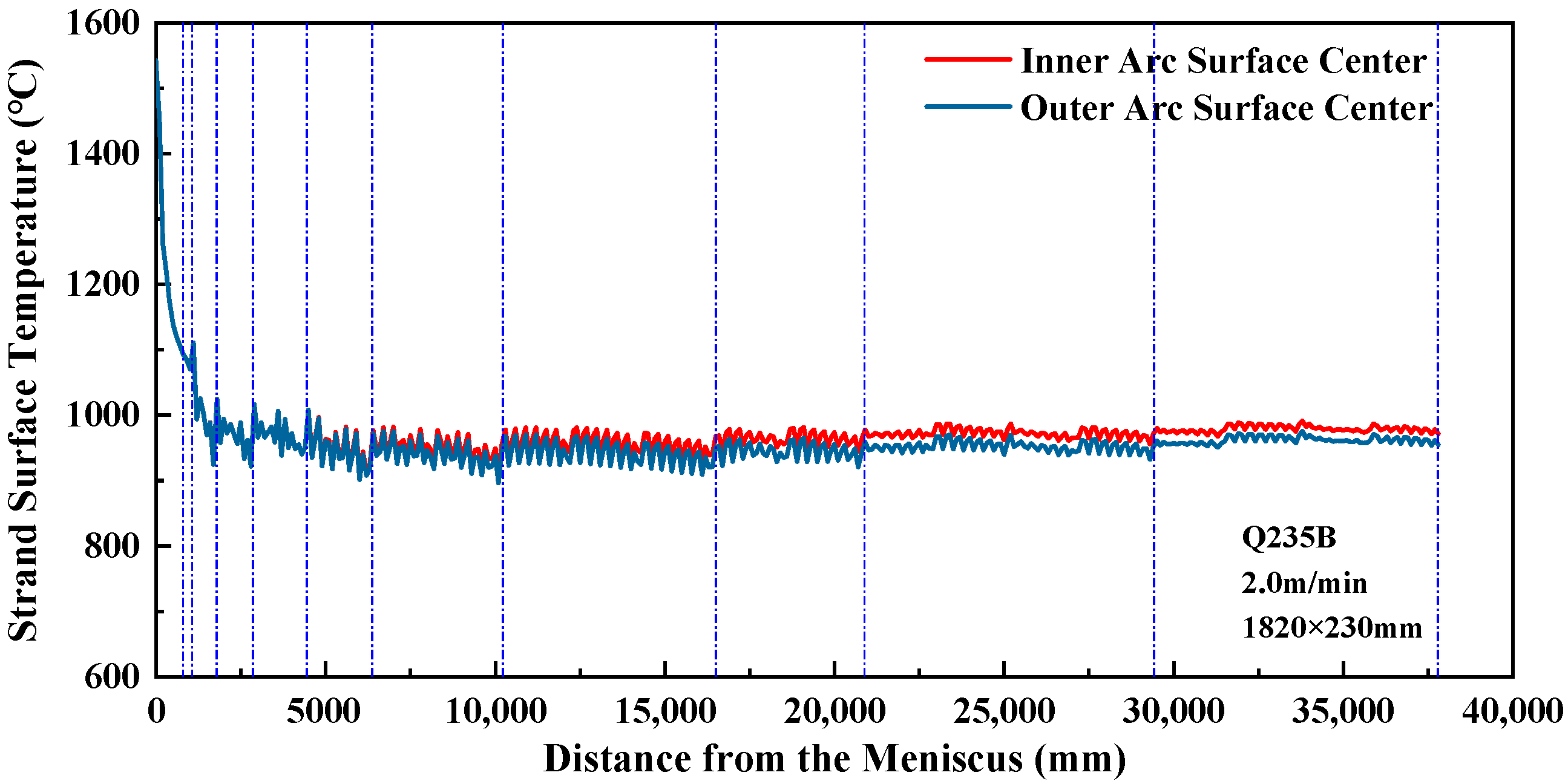
The variation curves of the inner- and outer-arc surface center temperatures are shown in
Figure 6.
4.6. Multidimensional Uniform Cooling Process System
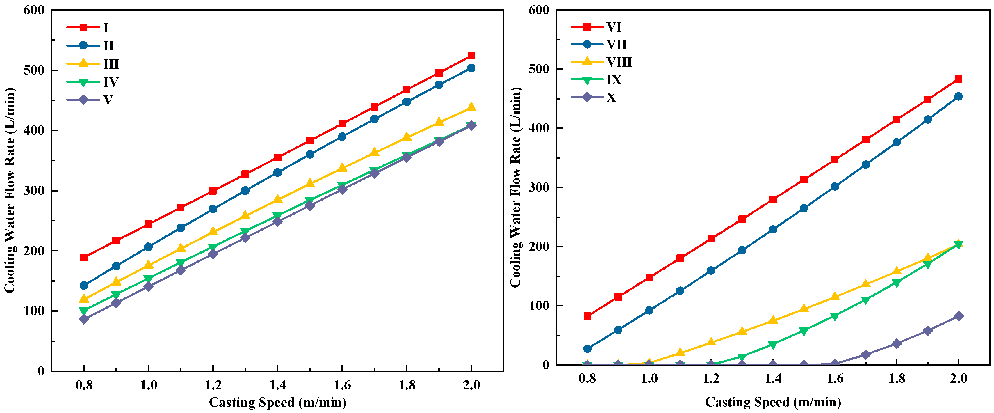
The secondary cooling model used in this study is a static control model, in which the water flow in each secondary cooling zone is controlled as a quadratic function of the casting speed. The variation in water flow with casting speed differs among zones. If the water flow changes significantly with casting speed, it may cause fluctuations in the slab surface temperature. In practical production, since the casting speed is not constant, large variations in water flow with speed can lead to significant fluctuations in the slab surface temperature, which is detrimental to surface quality.
After extensive simulation calculations, the variation in water flow with casting speed for each secondary cooling zone was determined. The curves of water flow versus casting speed for zones 1 to 10 are shown in
Figure 14.
From
Figure 14, it can be seen that the variation curves of water flow in each loop with casting speed follow the general cooling principle that higher casting speeds require larger water flow. For secondary cooling zones 1 to 5, the quadratic curves of water flow versus casting speed are almost linear, while for zones 6 to 10, the quadratic curves show a slight concave shape. According to continuous casting solidification and cooling theory, to achieve the same cooling effect, an increase in casting speed at high speeds requires a larger increase in water flow than the same speed increment at low speeds. Therefore, the slight concavity of the quadratic curve of water flow versus casting speed is reasonable.
The inner-arc surface center temperatures and temperature differences of the slab in each secondary cooling zone under different casting speeds are listed in
Table 11. The temperature differences between different speeds are calculated using the slab surface temperature at 1.2 m/min as the reference.
From
Table 11, it can be seen that, under different casting speeds, the inner-arc surface center temperature differences in secondary cooling zones 1 to 8 are all controlled within 20 °C. The small temperature differences help prevent large fluctuations in slab surface temperature caused by changes in casting speed during production, thereby ensuring surface quality. The larger temperature differences in zones 9 and 10 are due to variations in the slab solidification end positions at different speeds; at lower speeds, the solidification end occurs earlier, resulting in lower slab surface temperatures in the later stages of secondary cooling. Zones 9 and 10 are horizontal segments, where it is not necessary to maintain a high slab surface temperature. Instead, the goal is to ensure that the slab is fully solidified before the end of secondary cooling at high casting speeds.
Except for Zone 1, the slab surface temperature exhibits a slight decrease with increasing casting speed. This phenomenon arises because higher casting speeds require an increase in cooling water flow in the secondary cooling zones, which lowers the slab surface temperature. Meanwhile, the reduced residence time of the slab in the secondary cooling zone at higher casting speeds necessitates an appropriate increase in cooling water to ensure that the shell thickness is sufficient to withstand the ferrostatic pressure of the molten steel, thereby preventing breakout. Nevertheless, excessive cooling intensity may lead to an overcooling of the slab surface, and in severe cases, the surface temperature in the straightening zone may fall within the third brittle temperature range, exerting a detrimental effect on slab quality. In practice, casting speed is also adjusted according to production requirements. Fluctuations in casting speed cause variations in cooling water flow and, consequently, in surface temperature, and excessive temperature fluctuations can impair surface quality. The proposed multi-dimensional uniform cooling strategy is designed to ensure adequate shell thickness under high casting speeds, while maximizing the slab surface temperature and minimizing its fluctuation with casting speed, thereby achieving stable and improved slab quality.
Finally, the water flow rates for each secondary cooling zone corresponding to different casting speeds were fitted using the least-squares method, resulting in a multi-dimensional uniform cooling process model, as shown in
Table 12. i represents the cooling water flow on the inner arc of the slab, o represents the cooling water flow on the outer arc, s represents the cooling water flow on the slab sides, and io denotes the cooling water flow equally distributed between the inner and outer arcs.

