Abstract
This study focuses on the high-precision microhole machining of 304 stainless steel and explores a backwater-assisted picosecond laser trepanning technique. The laser used is a 30 W green picosecond laser with a wavelength of 532 nm, a repetition rate of 1000 kHz, and a pulse width of less than 15 ps. Experiments were conducted under both water-based and non-water-based laser processing environments to systematically investigate the effects of laser power and scanning cycles on hole roundness, taper, and overall hole quality. The experimental results further confirm the advantages of the backwater-assisted technique in reducing slag accumulation, minimizing roundness variation, and improving hole uniformity. In addition, thermal effects during the machining process were analyzed, showing that the water-based environment effectively suppresses the expansion of the heat-affected zone and mitigates recast layer formation, thereby enhancing hole wall quality. Compared with conventional non-water-based methods, the backwater-assisted approach demonstrates superior processing stability, better hole morphology, and more efficient thermal management. This work provides a reliable technical route and theoretical foundation for precision microhole machining of stainless steel and exhibits strong potential for engineering applications.
1. Introduction
In recent years, laser processing has increasingly replaced conventional mechanical machining in various fields due to its non-contact nature [1,2]. However, improper selection of laser parameters can result in issues such as excessive slag formation, an enlarged heat-affected zone (HAZ), and other defects [3], which compromise processing quality. Consequently, optimizing laser parameters and selecting an appropriate processing environment are critical. Laser drilling employs a high-power-density beam to induce localized heating, melting, and even vaporization of the material to create microholes (0–1000 μm). The laser pulse duration plays a key role in determining the underlying processing mechanisms. Longer pulse durations are generally associated with larger HAZ, recast layer deposition, and reduced hole quality. Common laser drilling techniques include percussion drilling, coaxial moving drilling, trepanning, and spiral drilling [4], among which the picosecond laser trepanning method proves particularly effective under low-power conditions.
In laser processing, air-based environments often lead to common defects such as an enlarged heat-affected zone (HAZ), accumulation of molten material, and interference from plasma plumes that hinder effective energy transfer [3]. To mitigate these issues, researchers have proposed water-assisted laser processing, wherein water serves both as a cooling medium and a flushing agent to remove molten debris, thereby reducing hole taper and minimizing the HAZ. However, traditional underwater laser processing introduces new challenges, such as surface water fluctuations and optical path deflection, which compromise process stability. To address these drawbacks, the backwater-assisted laser processing method has been developed. In this approach, a water layer is applied to the rear side of the workpiece, enabling effective cooling and debris removal while avoiding issues related to beam distortion or refraction [5].
In this study, picosecond laser micro-drilling of 304 stainless steel was investigated under backwater-assisted conditions. Experiments were conducted under such conditions, and a combined experimental and numerical modeling approach was employed to optimize key process parameters, such as laser power and scanning cycles. The machining performance under water-assisted and non-water-assisted conditions was systematically compared. Previous studies have demonstrated that this method significantly improves hole taper, reduces thermal effects, and is simple to implement with excellent processing outcomes [6].
2. Laser Drilling Experiment
2.1. Principle of Backwater-Assisted Laser Drilling
Laser drilling is a non-contact processing technique that enables rapid, localized material removal through beam–material interactions. When the laser beam is tightly focused, it generates extremely high power density within a small area, inducing rapid phase transitions such as heating, melting, and even vaporization of the target material, thereby forming microholes [7]. The underlying processing mechanism is closely related to the laser pulse duration. Based on pulse length, lasers are commonly categorized into nanosecond (ns), picosecond (ps), and femtosecond (fs) types [8,9].
For longer pulse durations, such as in nanosecond laser processing, material removal typically follows a thermal cycling mechanism. In this process, the laser energy first heats and melts the material, which is subsequently vaporized and expelled under high-temperature conditions. This mechanism often results in an enlarged heat-affected zone (HAZ), the formation of a recast layer, and degradation in hole morphology and quality [10].
Laser microhole processing can be classified into four types based on the relative motion between the laser beam and the workpiece [2]: laser percussion drilling, coaxial moving drilling, trepanning, and spiral drilling. In this study, a low-power picosecond laser was employed, and the machining path was designed as a series of concentric circles. As such, the picosecond laser trepanning technique was determined to be the most appropriate method for the intended application.
To balance the cooling benefits of the water medium with the stability of the laser processing beam path, researchers have proposed a backwater-assisted laser processing technique. This method involves introducing a 0.5 mm thick water layer on the backside of the workpiece. After the laser penetrates the material and forms a through-hole, water enters the hole via capillary action, interacting with the high-temperature zone. Studies by Mendiratta M and Prakash S [11] demonstrate that water intervention significantly enhances cooling and flushing effects in the laser processing region, effectively reducing recast layers, shrinking the heat-affected zone (HAZ), and suppressing hole shape deformation. Experimentally, hole taper was substantially reduced from 1.68° in an air environment to a minimum of 0.0286°, the HAZ was diminished by a factor of 3–4, and hole roundness became more stable.
Wang et al. [12] observed that when the water layer thickness exceeded 1 mm, underwater drilling caused severe chip blockage. They also found that maintaining a water layer on the backside while keeping the top surface exposed to air yielded results comparable to those obtained with a 0.5 mm thin water layer on the top, but without requiring complex setups. Moreover, this approach avoids the energy loss and focus degradation caused by beam refraction and scattering common in traditional underwater laser processing. Compared to other auxiliary methods such as magnetic or gas assistance, the backwater method features a simple structure, ease of operation, and promising engineering applications in microhole processing.
As illustrated in Figure 1, the initial drilling position resembles an open-air state. As drilling progresses, the laser penetrates the material, eventually creating an initial through-hole (pilot hole). As shown in Figure 1, under backwater-assisted conditions, the liquid medium penetrates into the through-hole via capillary action, positively influencing subsequent processing. Particularly under thinner water layer conditions, cavitation bubbles induced by the laser interact with the liquid–solid interface during their expansion and collapse, exhibiting asymmetric collapse behavior. This asymmetric collapse generates microjets directed toward the material surface, resulting in highly directional fluid impact effects [11,12].
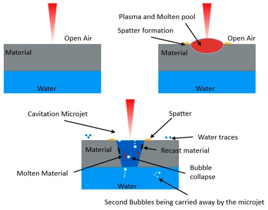
Figure 1.
The principle diagram of backwater-assisted laser drilling. Adapted with permission from Ref. [11]. Copyright 2025, Springer Nature.
These microjets not only enhance local material removal efficiency but also effectively flush away residual molten slag and secondary bubbles from the processing zone, thereby reducing the recast layer formation and improving the quality of the hole’s inner surface. A thinner water layer further enhances the directionality of the microjets, which improves the cleaning and shape control capabilities of backwater-assisted laser drilling. This mechanism is fundamental to achieving high-quality microhole processing [11,12].
2.2. Experimental Materials and Setup
The experimental setup employed a green picosecond laser (Amber NX GR-30S) manufactured by Bellin Laser Co., Ltd., Suzhou, Jiangsu, China) operating at a wavelength of 532 nm, with a maximum output power of 30 W, a repetition rate of 1000 kHz, a pulse duration of less than 15 ps, and a beam quality factor of M2 < 1.3. The laser system was controlled using Bellin Laser 2024 software. The laser beam diameter was 1.5 mm. In this experiment, picosecond laser ring-cutting paths were employed for microhole drilling in stainless steel. The processing path consisted of concentric circles with equal spacing, a defocus of 0, and a scanning speed of 20 mm/s. The objective was to investigate the effects of laser scanning cycles, peak power, and processing environment (with or without backwater assistance) on microhole machining quality. Using a single-factor variable approach, laser drilling experiments were conducted under both backwater-assisted and non-backwater-assisted conditions, and the influence of different parameters on drilling outcomes was compared and analyzed under identical processing conditions. Key evaluation metrics included hole entrance diameter, exit diameter, roundness, taper, and other geometric characteristics. The instruments used for measurement were the DSX100 ultra-depth-of-field optical microscope and a scanning electron microscope. The experimental material was a 304 stainless steel sheet with a diameter of 30 mm and a thickness of 0.3 mm. Its chemical composition is shown in Table 1. This material exhibits excellent thermal stability and processing adaptability, making it well suited for laser micro-machining. Considering that some experiments were conducted under backwater-assisted conditions, a 3D model of the water container and workpiece fixture was designed and fabricated using AutoCAD 2020 and SOLIDWORKS 2024 software to ensure the stability of the water layer and the precision of laser focusing during the experiments, as shown in Figure 2. This design guarantees the stability of the liquid–solid interface throughout the laser drilling process and offers versatility in the fixture structure, providing reliable support for the successful execution of the experiments.

Table 1.
Chemical Composition of 304 Stainless Steel.
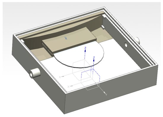
Figure 2.
Fixture Model.
Following the completion of the experimental setup design and preliminary preparations, comparative experimental plans were developed focusing on two key parameters: laser scanning cycles and peak power. Experiments were carried out under both backwater-assisted and non-backwater-assisted conditions. Within each experimental group, while keeping other factors constant, a single-factor method was employed to vary the scanning cycles and peak power independently, in order to investigate the specific effects of different parameter combinations on drilling quality, as summarized in Table 2. Before the experiment, preliminary processing of 0.3 mm thick 304 stainless steel was performed using a picosecond laser. It was found that under conditions where the power exceeded 21 W and the number of processing passes was greater than 15, the workpiece could be successfully penetrated with satisfactory results.
Table 2.
Experimental Parameters for Laser Processing.
The two processing methods are illustrated in Figure 3. In this study, the trepanning method was employed. In this approach, the laser beam follows pre-set concentric circles with equal spacing, with laser parameters and the scanning path defined by the system software. The concentric circle spacing is 10 μm, as shown in Figure 3c. Under open-air conditions, the workpiece is secured using a fixture prior to processing, as shown in Figure 3a [5].
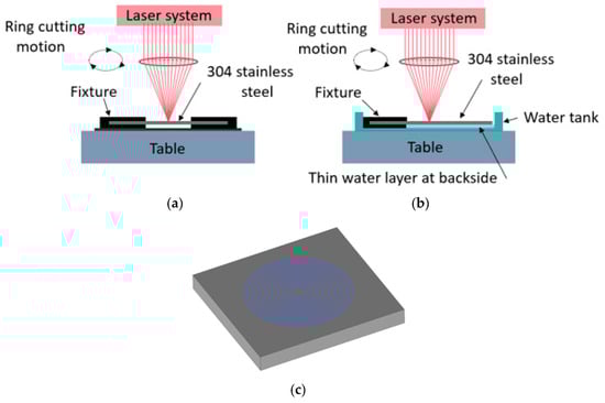
Figure 3.
Schematic diagram of laser processing in (a) open-air conditions and (b) backside water-assisted conditions; (c) ring cutting path. Adapted with permission from Ref. [11]. Copyright 2025, Springer Nature.
Under backwater-assisted drilling conditions, a 2 mm thick spacer was employed to maintain a consistent 2 mm water layer thickness. Distilled water was used throughout the backwater-assisted experiments, and the water was replaced after drilling each hole to prevent contamination that could adversely affect the experimental outcomes. During the measurement process, diameters of the hole entrance and exit were measured at four directions spaced at 45-degree intervals, as illustrated in Figure 3a. These measurements enabled the calculation of hole roundness and taper. The average of the four directional measurements was taken as the final hole diameter. The calculation formula is as follows:
where is the average entrance diameter, is the average exit diameter, , , , are the measured diameters at the four directions of the entrance, and , , , are the measured diameters at the four directions of the exit.
The roundness is obtained by the following formula:
Formula (2) quantifies the roundness of the hole by calculating the root mean square deviation of the measured diameters in four directions relative to the average value. Where is the entrance roundness, is the exit roundness, is the entrance diameter, is the exit diameter, , , , are the measured diameters at the four directions of the entrance, and , , , are the measured diameters at the four directions of the exit. The larger the values of and the worse the microhole roundness; conversely, the smaller the values of and , the better the microhole roundness.
As shown in Figure 4b, the taper is obtained by the following formula:
where is the top hole diameter, is the bottom hole diameter, and h is the material thickness.
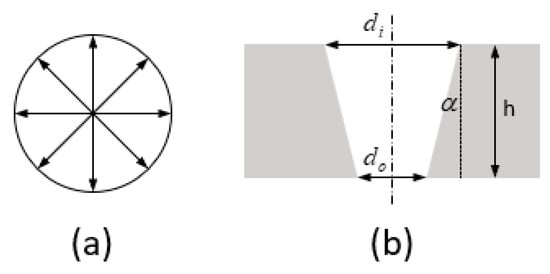
Figure 4.
(a) Measurement of Aperture and Roundness (b) Measurement of Taper.
2.3. Experimental Results
The sample drilling results obtained with non-water assistance are shown in Figure 5.
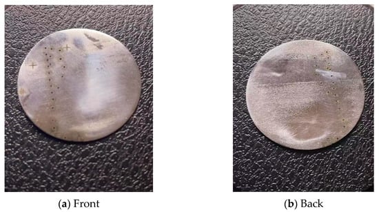
Figure 5.
Sample drilling results in a non-water assisted environment.
Figure 6a,b illustrate the variations in hole morphology under different laser powers and numbers of processing passes.
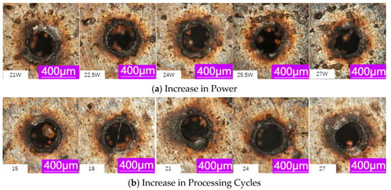
Figure 6.
Changes in Entrance Hole Morphology During Laser Drilling in a Non-Water Environment. ((a) is annotated with the power parameters for each cycle, and (b) is annotated with the processing cycle parameters).
The measurement results of microholes after backwater-assisted laser drilling are shown in the table below.
The sample drilling results obtained with backwater assistance are shown in Figure 7.

Figure 7.
Sample Drilling Results in a Backwater-Assisted Environment.
Figure 6 and Figure 8 illustrate the variations in hole morphology under different laser powers and numbers of processing passes.
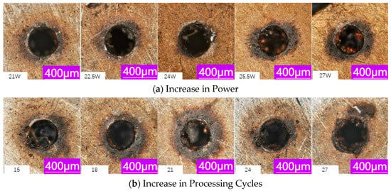
Figure 8.
Changes in Hole Morphology During Laser Drilling in a Non-Water Environment. ((a) is annotated with the power parameters for each cycle, and (b) is annotated with the processing cycle parameters).
3. Comparison and Analysis of Laser Drilling Results in Two Processing Environments
3.1. Laser Power
Table 3 and Table 4 present quantitative microhole measurements under non-water (air) and backwater conditions, respectively. As laser power increases from 21 W to 27 W, the entrance diameter generally grows in both environments. In air (non-water), the entrance diameter rises from about 335.7 μm at 21 W to a maximum of 368.5 μm at 24 W (Table 3, then stabilizes around 342–343 μm at 25.5–27 W. Under backwater assistance (Table 4), entrance diameters are consistently larger at the same powers—for example 356.4 μm at 21 W and 391.1 μm at 24 W—indicating deeper penetration and more effective material removal when the workpiece is cooled and flushed by water. Exit diameters change only moderately with power. In air the exit diameter varies roughly between 288–297 μm across 21–27 W, whereas in water it remains about 290–301 μm. Notably, the backwater holes tend to have slightly larger or more uniform exit diameters, reflecting reduced exit-side clogging.
Table 3.
Measurement Results of Microholes After Laser Drilling with Non-Water Assistance.
Table 4.
Measurement Results of Microholes After Laser Drilling with Backwater Assistance.
A striking difference appears in hole roundness. As shown in Figure 9, in the non-water environment, both entrance and exit roundness are much higher and more variable. For instance, entrance roundness in air decreases from ~33.0 μm at 21 W down to ~19.9 μm at 27 W (Table 3), while exit roundness fluctuates up to ~25.2 μm at 24 W. By contrast, backwater-assisted roundness values are dramatically lower. At 22.5 W (Table 4) the entrance roundness is only ~5.5 μm compared to ~23.8 μm in air (Table 3), and exit roundness is 12.0 μm in water versus 21.6 μm in air. Across all tested powers the backwater case yields entrance roundness in roughly the 5–13 μm range (versus 19–33 μm in air) and exit roundness in the 7–16 μm range (versus 18–25 μm in air). In other words, roundness “varies more dramatically” in air: the non-water holes show large irregularities (up to ~33 μm), whereas the water-cooled holes remain much more circular and consistent. This reflects the effect of the liquid: water cooling and microjet flushing remove molten debris and recast layer that would otherwise accumulate at the edges, so the hole walls stay more uniform. The result is a significant improvement in roundness stability under backwater assistance, which is beneficial for precision drilling.
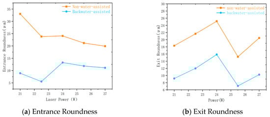
Figure 9.
Comparison of Microhole Roundness Between Backwater Assistance and Non-Water Assistance at Different Power Levels.
From Figure 10, it can be seen that under different laser power levels, the microhole taper variation trends for backwater assistance (blue line) and non-water assistance (orange line) are shown. The taper under backwater assistance is generally larger, especially at 24 W, where the taper reaches its maximum value close to 11. Afterward, it decreases but remains at a relatively high level. In contrast, the taper under non-water assistance varies more steadily. At lower power levels (such as 21 W), the taper is smaller, gradually increasing as the power increases. However, at higher power levels (such as 27 W), the taper decreases, clearly being lower than that of the backwater-assisted condition.
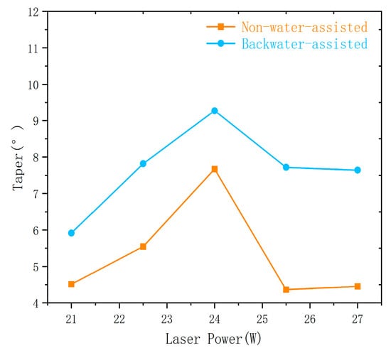
Figure 10.
Comparison of Microhole Taper Between Backwater Assistance and Non-Water Assistance at Different Power Levels.
The reason for the generally larger taper under backwater assistance could be that the cooling effect of the water layer is not able to completely suppress the heat accumulation when the laser power is too high, leading to overheating at the hole bottom and molten material expansion, which in turn increases the hole taper. Therefore, although backwater assistance has certain advantages in cooling, under high-power conditions, the thermal dynamic effects of the water layer and heat concentration could lead to a larger taper. It is necessary to optimize laser power and water layer thickness to improve hole quality.
3.2. Number of Processing Cycles
The influence of increasing the number of trepanning cycles (at fixed power) also differs strongly between the two environments. We examine the case of 22.5 W (the data are listed in Table 3 and Table 4). In air, the entrance diameter starts around 323.7 μm at 15 cycles and only reaches ~343.0 μm by 27 cycles, with some fluctuation (it even dips to 323.8 μm at 18 cycles and 325.4 μm at 24 cycles). The exit diameter in air is relatively stable around 271–307 μm except at 24 cycles where it anomalously drops to ~225.9 μm (Table 3), likely due to molten metal blocking the hole. Under backwater, however, the entrance diameter increases steadily from ~308.3 μm (15 cycles) up to ~428.0 μm (27 cycles), while the exit diameter stays above ~291 μm for all cycles. For example, at 24 cycles the backwater hole has entrance/exit diameters of 396.3/296.6 μm, whereas the air-drilled hole is only 325.4/225.9 μm. This indicates that the water-assisted process continues to deepen and widen the hole with each pass (thanks to effective flushing), whereas in air the hole can become constricted by recast over many cycles.
As shown in Figure 11, roundness trends further underscore the contrasting stability. In air, entrance roundness starts around 13.5 μm at 15 cycles, dips to ~7.3 μm at 21 cycles, then rises again (~21.3 μm at 27 cycles)—a wide swing. Exit roundness also fluctuates (from ~10.5 μm at 21 cycles up to ~22.6 μm at 24 cycles). By contrast, the backwater-assisted hole exhibits an extreme initial value followed by stability: at 15 cycles the entrance roundness is very large (~47.2 μm) because the hole is incomplete and the water has not entered. After 18 cycles, once the hole breaks through, the entrance roundness plummets to ~5.5 μm and remains low (10–27 μm thereafter). The exit roundness under water stays around 11–19 μm for most cycles (except the same initial unstable value at 15 cycles). Overall, after the early stage the water case consistently shows lower roundness. For instance, at 24 cycles the exit roundness is ~13.8 μm with backwater versus ~22.6 μm in air. These observations confirm that roundness varies much more in air-non-water roundness values oscillate dramatically from cycle to cycle–whereas backwater drilling yields a steadier profile once the process stabilizes. Practically, this means backwater-assisted drilling achieves a much more regular hole contour (better roundness stability), reducing the impact of sporadic spatters or uneven recast that plague the air process.
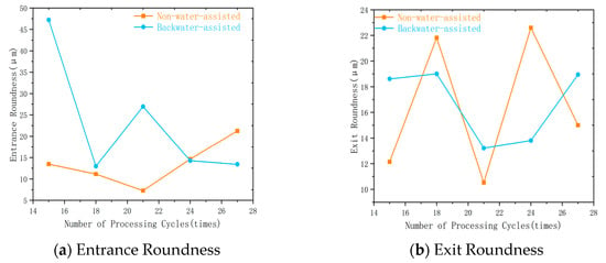
Figure 11.
Comparison of Microhole Roundness Between Backwater Assistance and Non-Water Assistance at Different Processing Counts.
From Figure 12, it can be seen that under different processing cycles, the taper of microholes changes with processing cycles in both backwater-assisted and non-water-assisted conditions. Under the backwater-assisted condition, the taper increases rapidly as the processing cycles increase, especially when the number of cycles exceeds 20, where the taper increases significantly, reaching its highest value at 24 and 27 cycles. Although the cooling effect of backwater assistance helps reduce the expansion of the heat-affected zone, at high power levels, the dynamic effects of the water layer (such as surface fluctuations and bubble formation) may cause excessive concentration of laser energy, leading to overheating at the bottom of the hole, thus causing a larger taper.
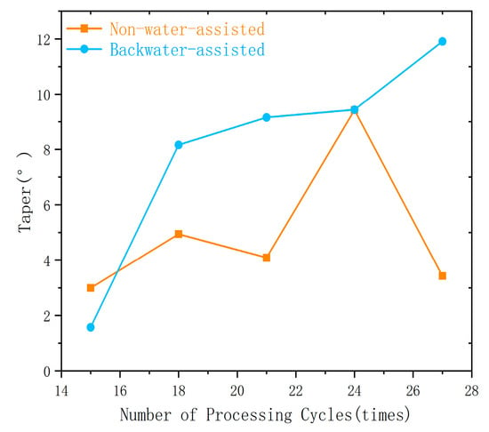
Figure 12.
Comparison of Microhole Taper Between Water-Based and Non-Water-Based Environments at Different Processing Counts.
In contrast, the taper under non-water assistance changes more gradually. Although the hole shape also undergoes certain changes at higher power, due to the lack of a cooling mechanism, more molten material accumulates at the hole entrance, and the hole shape is more unstable, with a slower increase in taper. Overall, while backwater assistance provides strong cooling effects, the dynamic changes in the water layer at high power conditions may lead to excessive expansion of the hole shape and a larger taper. Therefore, further optimization of process parameters is needed to ensure the stability and quality of the hole shape.
3.3. SEM Analysis of Microhole Morphology Under Different Environments
Figure 13 shows the scanning electron microscope (SEM) images of microholes obtained under different laser processing parameters and environmental conditions. The upper row displays the processing results under the backwater-assisted condition, while the lower row shows the results under the non-water-assisted condition. Through comparative analysis, it can be observed that under the backwater-assisted environment, the hole shape has a clear overall profile, with a regular hole entrance and almost no noticeable slag or recast layer attachment. In contrast, under the non-water-assisted environment, typical defects such as severe molten material accumulation at the hole edge, irregular profile, and rough inner walls are present.
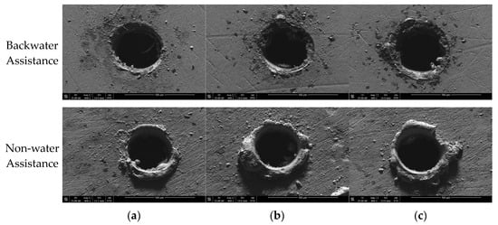
Figure 13.
Scanning electron microscope (SEM) images of microholes under different parameter conditions. (a) Power 21 W, defocus 0 mm, 15 processing cycles, scanning speed 20 mm/min. (b) Power 21 W, defocus 0 mm, 24 processing cycles, scanning speed 20 mm/min. (c) Power 25.5 W, defocus 0 mm, 15 processing cycles, scanning speed 20 mm/min.
Under the (a) parameter condition (power 21 W, processing cycles 15), the backwater-assisted sample shows a smooth and regular hole entrance with minimal slag deposition and a clear hole edge, whereas, under the non-water-assisted condition, noticeable recast layer accumulation is observed, and the hole entrance exhibits an irregular contraction, indicating that insufficient cooling leads to an expanded heat-affected zone and inadequate material flow.
Under the (b) condition (same power but with 24 processing cycles), the backwater-assisted environment still maintains good processing quality, and the hole shape does not show obvious deterioration, which demonstrates the significant suppressive effect of the water layer on heat accumulation. In contrast, the non-water-assisted sample shows hole edge collapse, deformation, and significant slag accumulation due to energy accumulation, with the hole wall roughness notably increased.
Figure 13c shows the results under high power (25.5 W) with 15 processing cycles. Under backwater-assisted conditions, even with high-energy input, the hole edge remains smooth and well defined, indicating that the laser-water coupled environment effectively controls the shape of the hole. The backwater environment helps to suppress material splashing and ensures that the hole geometry remains stable despite the high input energy.
In contrast, under non-water-assisted conditions, significant material splashing occurs around the hole edge, causing irregularities in the hole diameter and edge collapse. This results in a noticeable over-burning effect and morphological degradation, which negatively impacts the quality of the hole.
In conclusion, backwater assistance demonstrates excellent cooling and flushing effects in microhole laser processing. It not only inhibits the formation of recast layers and improves hole wall quality but also significantly enhances the stability and consistency of laser processing. In contrast, the non-water-assisted environment leads to high heat accumulation and material splashing, resulting in unstable hole shapes and concentrated defects. Therefore, backwater assistance is of significant practical importance and has great application potential for achieving high-quality laser microhole machining.
4. Study on Heat-Affected Zone Under Backwater-Assisted and Non-Water-Assisted Conditions
The heat-affected phenomenon refers to microstructural and property alterations in materials induced by thermal effects during processing. It is primarily manifested in two forms: the recast layer, which originates from resolidified molten material adhering to the substrate, and the heat-affected zone (HAZ), where the substrate undergoes significant microstructural and property changes without melting [13]. Such thermally affected regions severely degrade material performance, reducing service life and reliability, and in extreme cases may trigger fatigue fracture of the component, leading to catastrophic failure. Consequently, minimizing thermal effects is a critical requirement in material processing, and in aerospace applications, the presence of heat-affected regions must be strictly avoided [14,15].
Under backwater-assisted conditions, the presence of water on the backside or surrounding the workpiece provides an effective cooling effect, which significantly suppresses the formation of resolidified molten metal (recast layer). This effect is particularly evident under multiple processing cycles (24 cycles), where water cooling rapidly removes heat and reduces the expansion of the heat-affected zone (HAZ). During processing, bubbles may form, and their rupture, together with water convection, facilitates the quicker removal of slag and molten droplets from the processing zone, thereby improving the quality of the hole edge. However, due to the larger number of cycles, a certain thickness of recast layer (residual accumulation) may still be present at the hole bottom, as shown in Figure 14c, although it is thinner and more unevenly distributed compared to the non-water-assisted case. Overall, backwater assistance is beneficial for reducing the HAZ, improving edge quality, and promoting the removal of slag by flushing.
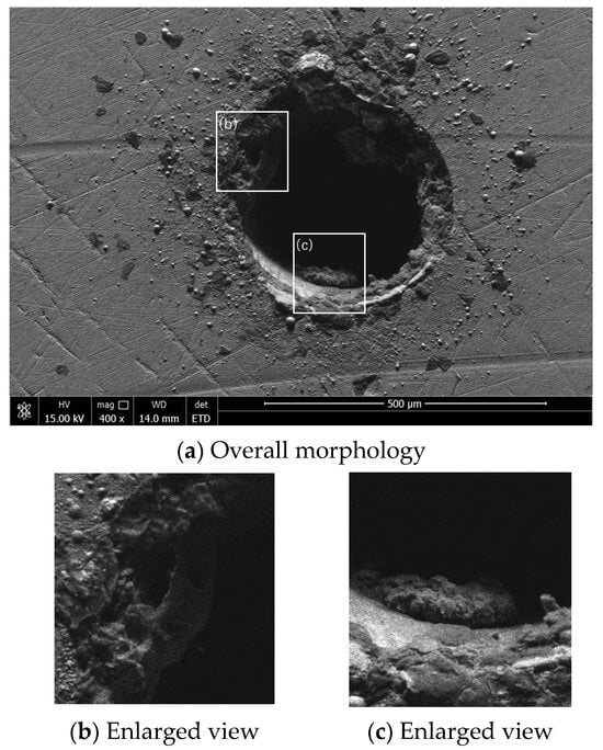
Figure 14.
Morphology of backwater-assisted laser drilling under the given processing parameters Power 21 W, defocus 0 mm, 24 processing cycles, scanning speed 20 mm/min.
Under non-water (air) conditions, the same high energy input combined with multiple processing cycles results in the formation of a pronounced heat-affected zone (HAZ) around the hole periphery and wall, with a large amount of molten metal resolidifying into a thick recast layer, as shown in Figure 15c. Since the slag at the hole edge and bottom cannot be effectively flushed or rapidly removed by fluid action, deposition and surface roughness are increased, as illustrated in Figure 15b. In a gaseous environment, bubble generation and impact are minimal, and the non-uniform temperature field provides insufficient convection to remove slag effectively. Consequently, the overall hole profile deteriorates, and the HAZ becomes more significant.
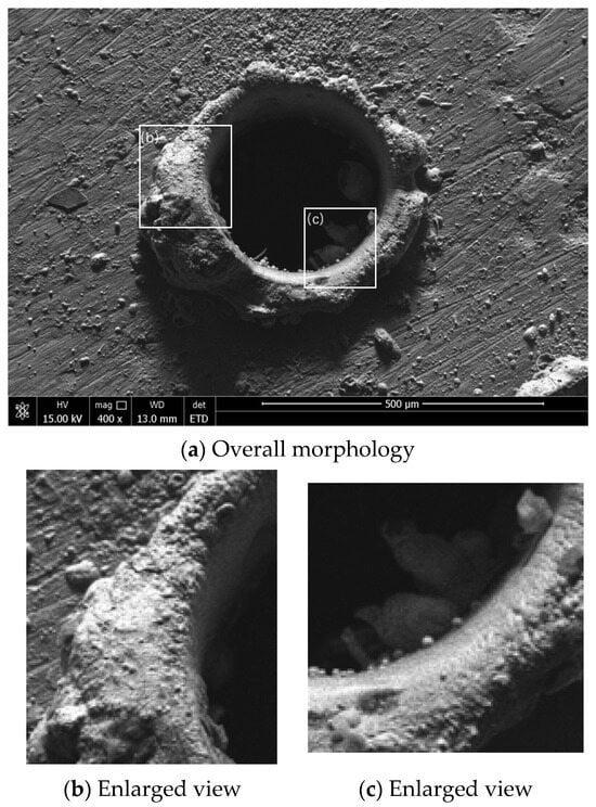
Figure 15.
Morphology of non-water-assisted laser drilling under the given processing parameters Power 21 W, defocus 0 mm, 24 processing cycles, scanning speed 20 mm/min.
When the number of processing cycles is reduced from 24 to 15, the total energy input during hole formation decreases accordingly. Combined with backwater cooling, the reduced heat accumulation further limits the formation of the recast layer, as shown in Figure 16c, while the heat-affected zone (HAZ) becomes narrower. At the same time, water flushing and bubble collapse continue to facilitate the removal of slag generated during processing, resulting in a smoother morphology at the hole wall and entrance, as illustrated in Figure 16b. With fewer total cycles, residual material at the hole bottom is also reduced, and fluctuations in hole diameter and taper may be minimized.
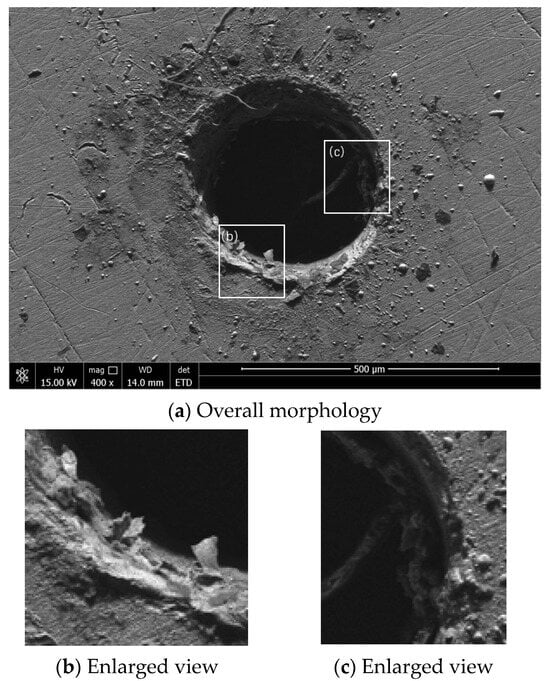
Figure 16.
Morphology of backwater-assisted laser drilling under the processing parameters Power 21 W, defocus 0 mm, 15 processing cycles, scanning speed 20 mm/min.
As shown in Figure 17, when the number of processing cycles is reduced to 15, although the energy input decreases, the air environment still lacks effective cooling and flushing mechanisms. Compared with the backwater-assisted case at 15 cycles, the hole wall and entrance still exhibit noticeable recast layers and a certain heat-affected zone (HAZ). While these issues are alleviated compared with the 24-cycle condition, they are still present. Due to the low efficiency of slag removal, the hole profile and surface roughness remain inferior to those of the backwater-assisted sample. This indicates that even reducing the number of cycles does not fundamentally resolve problems such as thermal accumulation and material splashing.
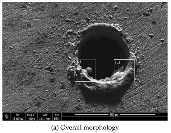
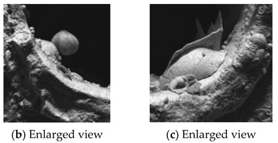
Figure 17.
Morphology of non-water-assisted laser drilling under the processing parameters Power 21 W, defocus 0 mm, 15 processing cycles, scanning speed 20 mm/min.
Although reducing the number of processing cycles partially mitigates the formation of heat-affected zones and recast layers, the lack of effective cooling and flushing in the air environment still results in limited improvement in hole wall and surface quality. The fundamental advantages of water-assisted cooling and flushing cannot be compensated under non-water-assisted conditions, highlighting the clear superiority of backwater-assisted processing.
5. Conclusions
In this study, high-precision microholes in 304 stainless steel were machined by picosecond laser trepanning under both conventional (air) and backwater-assisted conditions.
- (1)
- Backwater assistance outperforms the non-water environment in terms of hole roundness and hole wall surface quality. However, the taper angle shows greater deviation compared to the non-water condition.
- (2)
- Backwater can effectively remove molten material and dissipate heat, reducing the recast layer and the heat-affected zone.
- (3)
- Backwater assistance provides an effective means to improve microhole machining quality and has practical value for high-precision manufacturing.
In the next step, the backwater-assisted method can be extended to more complex conditions and quality management in laser manufacturing production.
Author Contributions
Methodology, R.X., J.Z. and X.H.; Validation, Y.R. and L.X.; Formal Analysis, Y.R. and K.X.; Investigation, R.X., J.Z. and C.W.; Resources, C.W.; Data Curation, L.W., L.X., X.H. and K.X.; Writing—Original Draft, R.X.; Writing—Review and Editing, L.W. All authors have read and agreed to the published version of the manuscript.
Funding
This work was supported by the National Natural Science Foundation of China (52375434 and 52205469) and by the Major Research Projects of the Natural Science Research Foundation of Jiangsu Higher Education Institutions (23KJA460003).
Data Availability Statement
The original contributions presented in this study are included in the article. Further inquiries can be directed to the corresponding author.
Conflicts of Interest
The authors declare no conflict of interest.
Correction Statement
This article has been republished with a minor correction to the copyright information. This change does not affect the scientific content of the article.
References
- Du, S.; Zhang, C.; Sun, W.; Ma, Y.; Yao, Y. Application of laser microfabrication technology in the medical device field. Optoelectron. Eng. 2023, 50, 220306. [Google Scholar]
- Jia, H. Research on Femtosecond Laser Processing Method for Aviation Blade Shaped Film Holes. Master’s Thesis, Xi’an Institute of Optics and Precision Mechanics, Graduate School of Chinese Academy of Sciences, Xi’an, China, 2013. [Google Scholar]
- Zhang, T. Study on the Mechanisms of Molten Splashing, Recast Layer, and Micro-Crack Formation During Millisecond Laser Drilling. Master’s Thesis, Nanjing University of Science and Technology, Nanjing, China, 2017. [Google Scholar]
- Zhang, T. Preparation and Sensing Research of Microhole Structure Optical Fiber Devices. Master’s Thesis, Xi’an Petroleum University, Xi’an, China, 2019. [Google Scholar]
- Ren, N.; Zhang, J.; Li, Z.; Qi, D.; Zhang, H.; Xia, K. The Effects of Static- and Flowing-Water-Assisted Methods on the Quality of Femtosecond Laser Drilling of Thermal-Barrier-Coated Superalloys. Metals 2025, 15, 261. [Google Scholar] [CrossRef]
- Zhang, J.; Tang, W.; Du, Y. Injection nozzle hole processing technology. Mod. Automot. Power 2010, 1, 43–46. [Google Scholar]
- Zhanwen, A.; Zou, G.; Yu, H.; Feng, B.; Du, C.; Liu, L. Polarization-dependent, beam reflection-regulated hole shaping dynamics visualized by in-situ imaging of ultrafast laser drilling process. Precis. Eng. 2024, 86, 153–159. [Google Scholar]
- Chichkov, B.N.; Momma, C.; Nolte, S.; Von Alvensleben, F.; Tünnermann, A. Femtosecond, picosecond, and nanosecond laser ablation of solids. Appl. Phys. A 1996, 63, 109–115. [Google Scholar] [CrossRef]
- Ready, J.F. Effects of High-Power Laser Radiation; Academic Press: Cambridge, MA, USA, 1971. [Google Scholar]
- Mazumder, J.; Steen, W.M. Heat transfer model for CW laser material interaction. J. Appl. Phys. 1980, 51, 941–947. [Google Scholar] [CrossRef]
- Mendiratta, M.; Prakash, S. Investigation and process optimization of backside thin water layer assisted laser micro-drilling of titanium. Lasers Manuf. Mater. Process. 2025, 12, 318–345. [Google Scholar] [CrossRef]
- Wang, W.; Song, H.; Liao, K.; Mei, X. Water-assisted femtosecond laser drilling of 4H-SiC to eliminate cracks and surface material shedding. Int. J. Adv. Manuf. Technol. 2021, 112, 553–562. [Google Scholar] [CrossRef]
- Wang, L.; Rong, Y.; Xu, L.; Wu, C.; Xia, K. Experimental Study and Defect Control in Picosecond Laser Trepanning Drilling of Superalloy. Metals 2025, 15, 893. [Google Scholar] [CrossRef]
- Song, Q. Fundamental Study on Laser Machining Assisted by Jet Electrolyte. Ph.D. Thesis, Nanjing University of Aeronautics and Astronautics, Nanjing, China, 2008. [Google Scholar]
- Jiang, J. Study on Micropore Machining of Metal Materials by Picosecond Laser. Ph.D. Thesis, Beijing University of Technology, Beijing, China, 2014. [Google Scholar]
Disclaimer/Publisher’s Note: The statements, opinions and data contained in all publications are solely those of the individual author(s) and contributor(s) and not of MDPI and/or the editor(s). MDPI and/or the editor(s) disclaim responsibility for any injury to people or property resulting from any ideas, methods, instructions or products referred to in the content. |
© 2025 by the authors. Licensee MDPI, Basel, Switzerland. This article is an open access article distributed under the terms and conditions of the Creative Commons Attribution (CC BY) license (https://creativecommons.org/licenses/by/4.0/).