Article

Study on Double-Curvature Metal Plates Sequential Forming with Heat-Assisted Incremental Bending Based on Minimum Energy Method

1
School of Mechanical and Electrical Engineering, Guangdong Polytechnic of Industry and Commerce, Guangzhou 510510, China
2
Shenzhen Institutes of Advanced Technology, Chinese Academy of Sciences, Shenzhen 518055, China
3
Shenzhen Key Laboratory of Precision Engineering, Shenzhen 518055, China
*
Authors to whom correspondence should be addressed.
Metals 2025, 15(10), 1124; https://doi.org/10.3390/met15101124
Submission received: 1 July 2025 / Revised: 14 September 2025 / Accepted: 16 September 2025 / Published: 10 October 2025
(This article belongs to the Special Issue Advances in Metal Forming and Plasticity)

Abstract

This study presents a high-frequency heat-assisted incremental bending process for the high-efficiency, high-precision forming of medium-thickness (≥3 mm) double-curved metal plates, addressing the limitations of traditional stamping and line heating methods in aerospace and marine applications. A minimum energy loading path strategy is proposed to optimize the forming trajectory and reduce residual stress. A coupled thermomechanical finite element model was developed, incorporating high-frequency induction heating, temperature-dependent material properties, and Coulomb friction. The model was validated through experiments on Q235 steel plates. Results show that the proposed process reduces the peak forming force and decreases the number of forming points compared to conventional cold incremental bending. Springback is reduced, and the final shape accuracy reaches within 3 mm deviation from the target geometry. Double-curvature sail and saddle-shaped plates were successfully fabricated, demonstrating the feasibility and effectiveness of the method. This work provides a promising solution for low-cost, flexible manufacturing of complex medium-thickness components.

1. Introduction

Double-curvature metal plates are widely used in aerospace, automotive, shipbuilding, and other industrial fields. How to accurately and rapidly form bidirectional curvature sheet metal is always the focus of the industry. In order to solve this problem, research institutions and enterprises have made many efforts in the past decades. Generally speaking, the workpiece with bidirectional curvature used in the manufacturing industry can be divided into two types according to the definition of Gaussian curvature; when the value of Gaussian curvature is positive, the surface is spherical and it is mainly represented by the sail surface, as shown in Figure 1a. When the Gaussian curvature value is negative, the surface is pseudo spherical and it is mainly represented by the saddle surface, as shown in Figure 1b.
For the production of double-curvature plates in the shipbuilding industry, the shipyard usually adopts the roller bending machine to process the unidirectional curvature plate first, and then the line heating method is adopted to form the other direction curvature plate, as shown in Figure 2. However, it is difficult to accurately control the heating and cooling process, and the inhomogeneity of sheet material in the line heating process could result in poor forming accuracy of the workpiece. In addition, this processing requires experienced workers to operate for a long time, and it has low efficiency, poor working environment, and high labor intensity.
With the development of forming technology, more effective automatic forming technologies based on the line heating method have become the focus of many research institutions. The “IHI-α” line heating plate robot was developed by Ishikawajima-Harima Heavy Industries Co., Ltd.; “iCALM” line heating plate robot was developed by Seoul National University [1,2]. Although the processing efficiency and the workers’ working environment have been improved, the processing accuracy of the metal plates cannot be guaranteed, so other automatic machining methods for 3D free complex surfaces are proposed. Li et al. proposed multi-point sheet forming technology (MPF) [3,4,5]. Its working principle is to discrete the whole traditional stamping die into a series of regular arrangement and a height-adjustable basic body, change the height of each basic body through the computer automatic control of the displacement of each basic body, and construct the die with a different forming surface to realize the rapid and digital plastic forming of sheet metal. This method can form the sheet shape at one time, but the workpiece is prone to obvious indentation and wrinkle defects, and the machine size, cost, and forming force are very large.
Flexible roll forming is another technology for forming complex metal surfaces. It is divided into array roll forming (LARS) and continuous roll forming (CRF). The array roller forming machine consists of a pair of upper and lower symmetrical roller components [6,7]. By adjusting the relative position of each roller, the longitudinal curvature will be generated in the transverse curvature rolling process, so as to realize the bidirectional curvature plate bending forming. Continuous roll forming process is also a flexible forming method of complex bending sheet based on the rolling principle [8,9,10]. It uses a series of points to control a pair of bendable rollers as forming tools to form a hyperboloid. However, up to now, roll forming has been mostly limited to sheet metal parts with large springback and small forming curvature.
Unlike traditional flame heating methods, laser heating has the advantages of precise focus and easy control, and is environmentally friendly. So the laser bending method is widely used in the research of the complex surface forming process. Kim and Na [11,12] proposed a distance-based and angle-based method to generate the laser scanning path strategy, and they successfully obtained the workpiece with predetermined shape. Yang et al. [13] employed the finite element method to analyze the temperature field, stress-strain field, and deformation field in the 3D forming process of a square plate into a spherical crown using the spider line scanning strategy. Safari et al. [14] proposed a helical scanning strategy for saddle-shaped laser forming and conducted an experimental study on it. In addition, the influence of processing parameters such as screw diameter distance, screw diameter number, in-out screw diameter and back-in-out screw diameter on deformation behavior of saddle-shaped plate was also studied. Chakraborty et al. [15] proposed a new laser forming method for bowl-shaped plates by irradiating the center of a flat circular blank with a stationary laser beam. The effects of laser irradiation time and spot diameter on the bending and asymmetry of the formed surface were studied. Hong et al. [16] proposed a laser bending forming method based on the principle of minimum energy and integrated strain control. Based on nonlinear deformation theory, using the finite element method and minimum energy principle, the hyperbolic panel is expanded into a single panel. The strain distribution can be obtained by the optimized plane unfolding process, and the laser heating path can be planned according to the combined strain obtained by in-plane strain and out-of-plane strain. Based on the deformation database, the shape difference between hyperboloid and expanded single surface is used to determine the heating conditions. The effectiveness of this method is verified by two hyperboloid experiments.
The complex curved surface of sheet metal can be formed by laser bending, but there are some limitations in laser bending. First, the plastic deformation of each scan is very small, and it is difficult to bend the thick plate. Secondly, the bending direction of the plate is difficult to control. In order to reduce the impact of springback on sheet metal forming accuracy and improve the sheet metal’s formability and forming efficiency, laser bending forming assisted by external load was studied.
Guan et al. [17] simulated the laser bending model assisted by external load. Experimental results showed that this method can greatly improve the bending plastic deformation of sheet metal. Compared with the traditional bending process, this process had the advantages of high forming precision, high flexibility, and avoiding plastic instability. Yao et al. [18] simulated the forming process of cantilever laser bending plates and they pointed out that pure compression and pure bending (toward the laser direction) would increase the bending angle, while pure stretching and pure bending (away from the laser direction) would decrease the bending angle. Liu et al. [19] found that the deformation direction could be controlled by changing the preload direction and its value. With the increase in preload, the bending angle of the metal plate increased obviously. And they succeeded in obtaining complex plates with airplane shapes and cube shapes. Gisario et al. [20,21,22] adopted the method of laser-assisted bending with external force. Under different experimental conditions, the bending angle of a titanium alloy plate could be bent to about 80–140°, the bending angle of an aluminum plate was about 90–140°, and the bending angle of an AISI 304 stainless steel plate was about 70–140°.
In the above methods, the metal plates must be clamped together with custom-made devices during the forming processes, which increases the manufacturing cost and limits the application for metal plates with complex curvature. Therefore, it is very necessary to develop the heat-assisted incremental bending to realize the metal plates with complex and large curvature.
In order to solve the problems in the sheet metal forming methods we mentioned above, our team proposed a new incremental bending forming method with small forming force, high processing efficiency, and high forming accuracy [23]. In this paper, the forming of sail-shaped plates and saddle-shaped plates is studied by sequential bending forming strategy combined with incremental bending forming technology.

2. Principle of Heat-Assisted Incremental Bending

2.1. Minimum Energy Principle [23]

Heat-assisted incremental bending is a flexible thermomechanical forming technique employed for fabricating metal plates, particularly those requiring complex geometries and significant curvatures. While conventional incremental forming is typically limited to thin sheets, this method is specifically adapted for the shaping of large-scale, thick metal plates. The process is rooted in the principle of incremental deformation, enhanced by localized heating to improve formability.
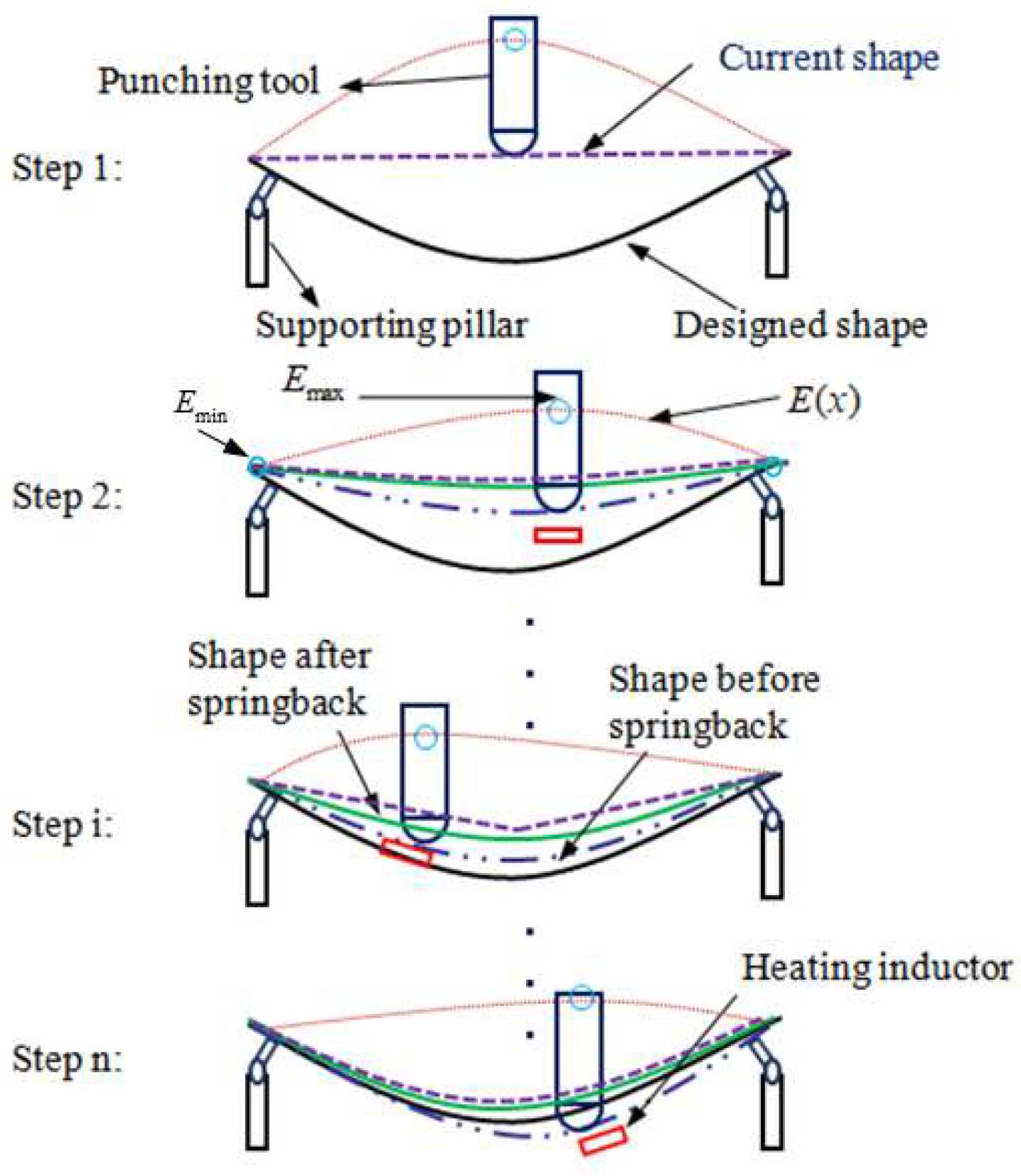
The deformation behavior follows the Euler-Bernoulli beam bending theory (Figure 3). In practice, the metal plate is clamped along its edges using supporting pillars. A punch then deforms the plate incrementally at discrete locations, with each step involving controlled indentation depths tailored to progressively achieve the target profile. Concurrently, an induction heating system is utilized to locally heat the material around each forming point, reducing flow stress and facilitating plastic deformation.
For dieless incremental bending, the path along which the punch loads the plate significantly influences both forming accuracy and efficiency. In this work, the incremental loading trajectory is determined by applying the minimum energy principle derived from Euler-Bernoulli beam theory, ensuring an optimized forming sequence. The energy of the beam shown in Figure 3 can be expressed as
Q = x 1 x 2 q ( x ) E ( x ) 1 2 E I 2 E ( x ) / x 2 2 d x
where q ( x ) is the external force and E ( x ) is the error between the current shape and the desired shape. E is the elastic modulus of the material, I is the moment of inertia of the cross-section, and together they constitute EI (flexural rigidity).
q ( x ) is a concentrated force load and can be defined as q ( x p ) , and x p ( x 1 x p x 2 ) is the position of the punching point.
Now, substituting q ( x p ) into Equation (1), the energy of the beam can be simplified as
Q = q ( x p ) E x p + C
where C is a constant.
x p should meet the following two conditions based on the minimum energy principle.
Q / x p | x p = q x p E x p / x p = 0 2 Q / x p 2 | x p = q x p 2 E x p / x p 2 > 0
The minimum and maximum error points can be calculated by Equation (3). The supporting points at the two ends of the beam are the minimum error points, and the punching point is the maximum error point.

2.2. Virtual Spring Theory

As shown in Figure 4, the metal plates with double curvature were discretized into a series of strips along the x and y directions, respectively, and each strip bent as a beam. However, in order to describe the interaction among these strips, virtual springs were introduced. In the incremental bending process, the Euler-Bernoulli beam theory was applied to compute the bending of these strips. Therefore, a metal plate can be defined as
j = 1 n E j I j 4 k x i j w i / x 4 + j = 1 n p j 2 k x i j w i / t 2 = q ( x , t )
j = 1 n E j I j 4 k y i j w i / x 4 + j = 1 n p j 2 k y i j w i / t 2 = q ( y , t )
where i , j are strip numbers, E is the elastic modulus, I is the second moment of area, w i is the deflection of the pressed strip, u is the mass per unit length, q ( x , t ) , q ( y , t ) is the external load, n is the total number of strips, and k x i j · k y i j are the virtual spring coefficient between different strips.
When k x i j = 0 or k y i j = 0, there is no interaction between adjacent strips. Conversely, the greater the values of k x i j and k y i j , the stronger the coupling effect. In practical applications, for single-curvature plate forming, k x i j can be set to zero due to the negligible inter-strip influence. However, in double-curvature forming, the interaction among strips intensifies as the punch position and indentation depth vary, which can lead to shape distortions and a decline in forming accuracy. Thus, suppressing this mutual interference is essential for high-precision fabrication. This can be achieved by introducing localized support structures and applying targeted heating beneath each strip, tailored to its specific curvature.

2.3. Flexible Supporting System

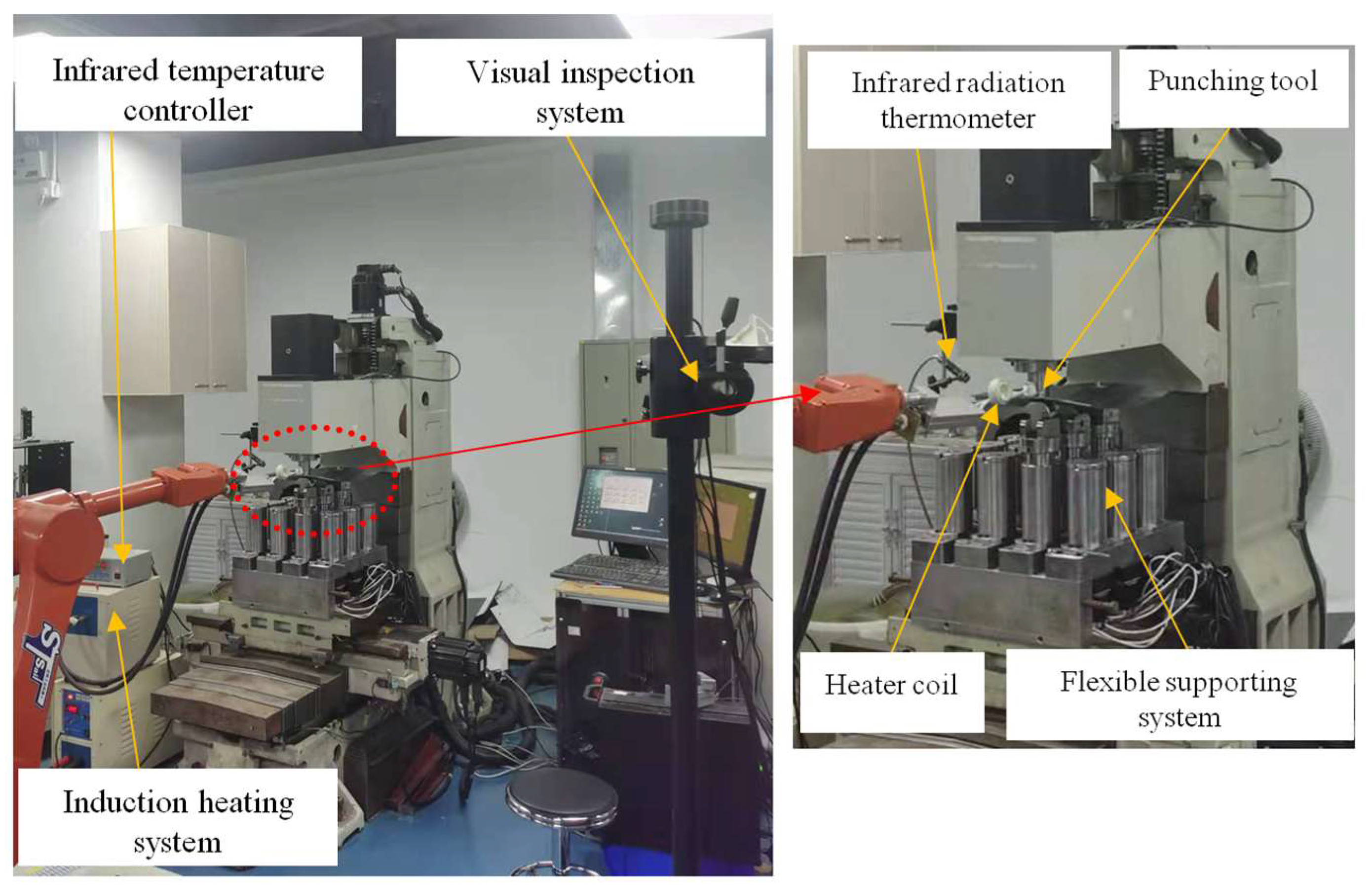
The flexible supporting system is a critical component in the incremental bending process. As illustrated in Figure 5, it consists of a 4 × 3 array of supporting pillars. Each pillar is composed of an electromagnet or screw mechanism, a rotatable head, and an adjustable lifting column. During forming, the metal plate is secured to the rotatable head via screws or electromagnetic clamping. The rotatable head enables multi-directional pivoting around its central axis, accommodating angular changes as the sheet metal bends. Meanwhile, each lifting column is individually controlled by a servo motor, allowing independent vertical adjustment to dynamically match the workpiece deformation throughout the process.
Notably, thanks to the discrete matrix layout and height-tunable pillars, the system offers adaptable and versatile support for workpieces with diverse geometries. The supporting pillars are categorized into fixed and auxiliary types. For single-curvature and variable-curvature plates, the fixed pillars are positioned at the four corners of the matrix and maintain a constant height during forming, providing stable primary support, while the auxiliary pillars assist in local shape adaptation.

3. Experiments and Simulations

3.1. Experimental Setup

Based on the forming principle shown in Figure 3, an incremental bending prototype with the maximum punching force of 20 kN was built. As shown in Figure 5, the prototype machine consisted of a punching tool, 4 × 3 supporting pillars, a control system, and a visual inspection system. In addition, a robot and an induction heating system were also introduced. The dimension of the machine was 1750 mm × 1750 mm × 1950 mm. A visual inspection system was employed to capture the geometric profile of the workpiece. The induction heating setup consisted of a high-frequency induction heater, an infrared temperature controller, and an infrared radiation thermometer for real-time thermal monitoring. The infrared temperature controller was held in place by a robotic arm, enabling precise positioning and continuous temperature feedback during the forming process.

3.2. Experimental Procedure

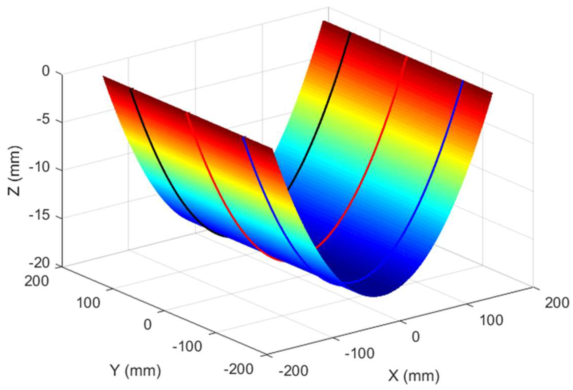
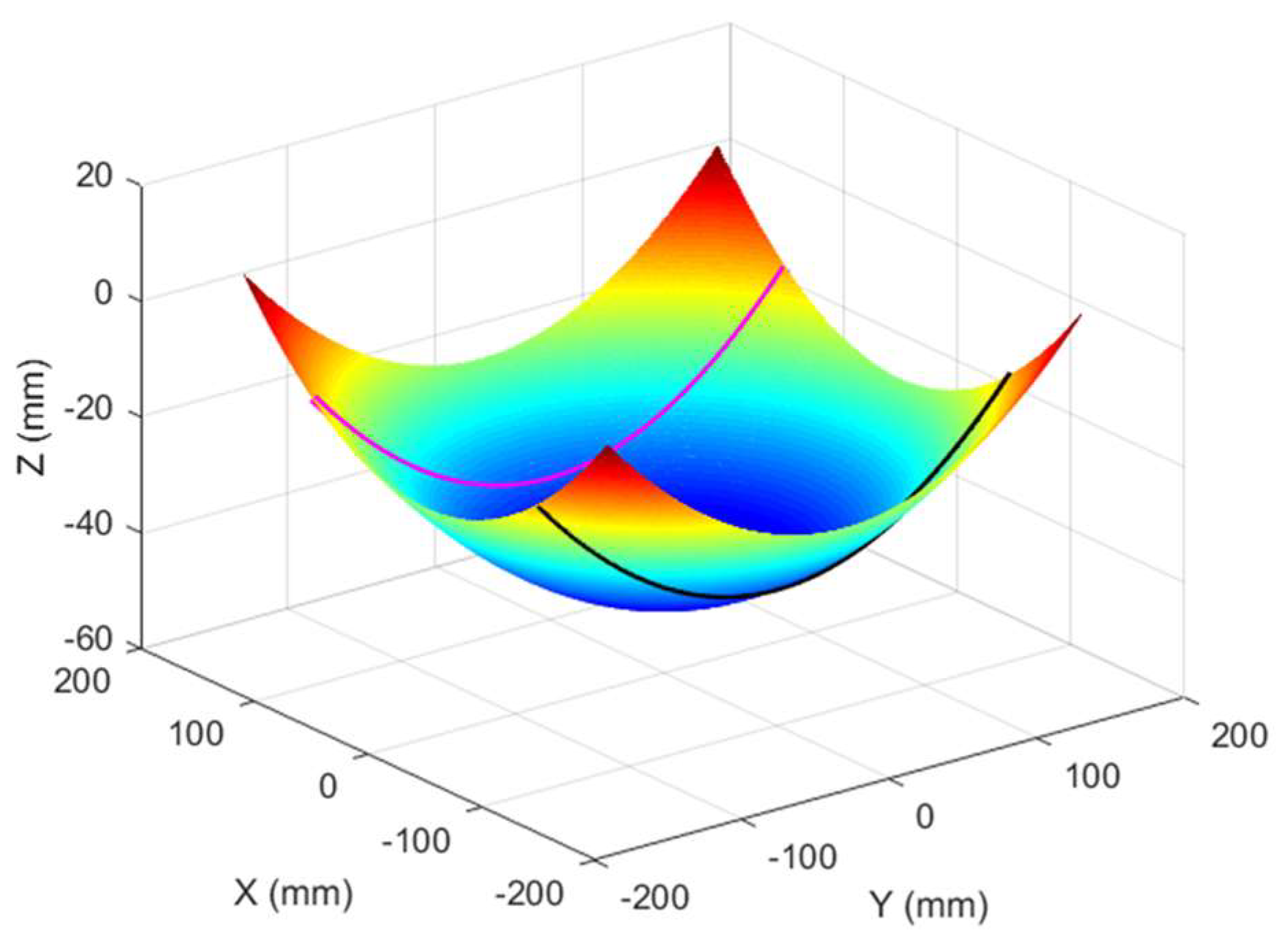
For the forming of the bidirectional curvature plate, the shipyard usually adopts the roller bending machine to process the unidirectional curvature plate first, and then adopts the line heating method to form the other direction curvature plate. The line heating method mentioned above has many shortcomings, so in this section we combined it with incremental bending forming technology, using sequential bending forming strategy and minimum energy processing trajectory to study the forming process of sail-shaped plates and saddle-shaped plates. Figure 6 and Figure 7 show the design shape and loading trajectory of the single-curvature plate.
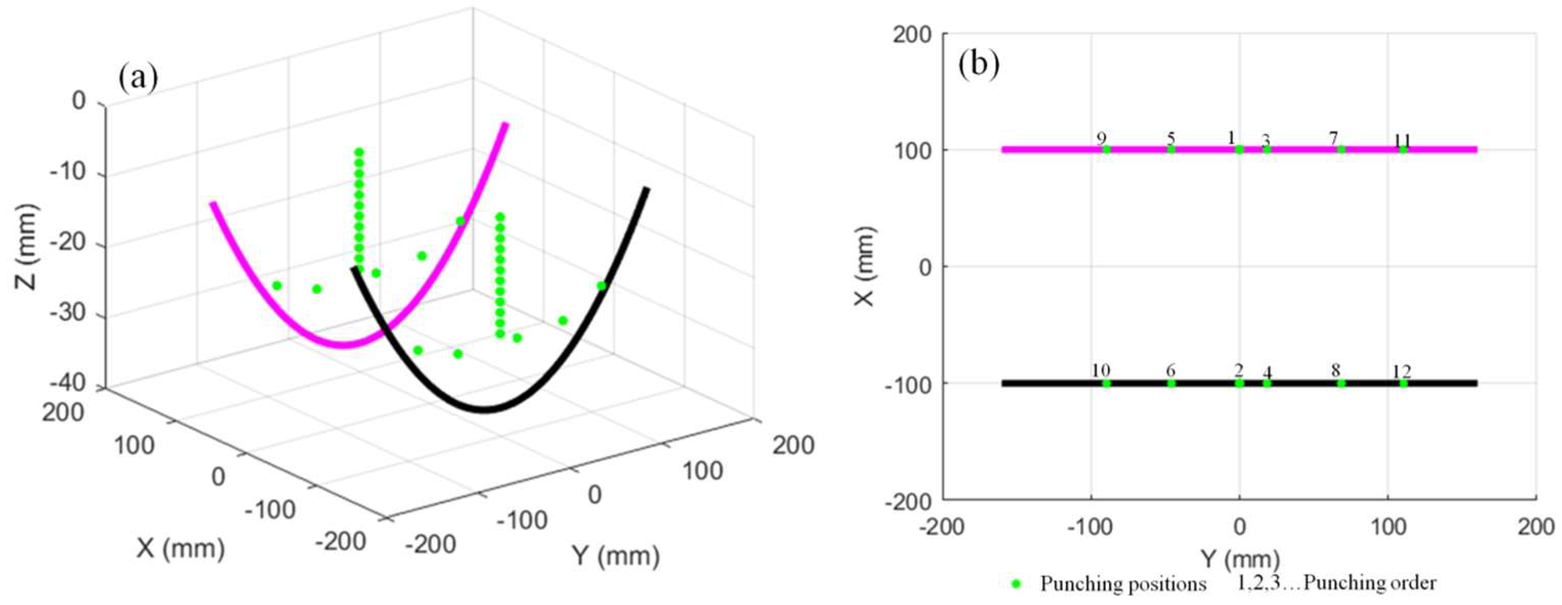
Figure 8 and Figure 9 show the design shape of the sail-shaped plate and the forming loading trajectory in the second curvature direction, respectively. Figure 10 shows the experimental figure of forming the sail-shaped plate.
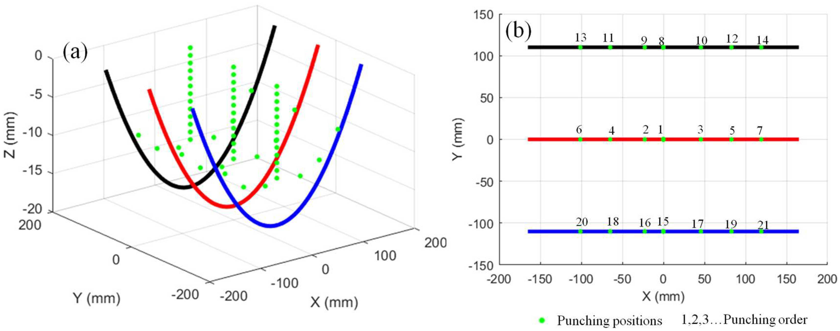
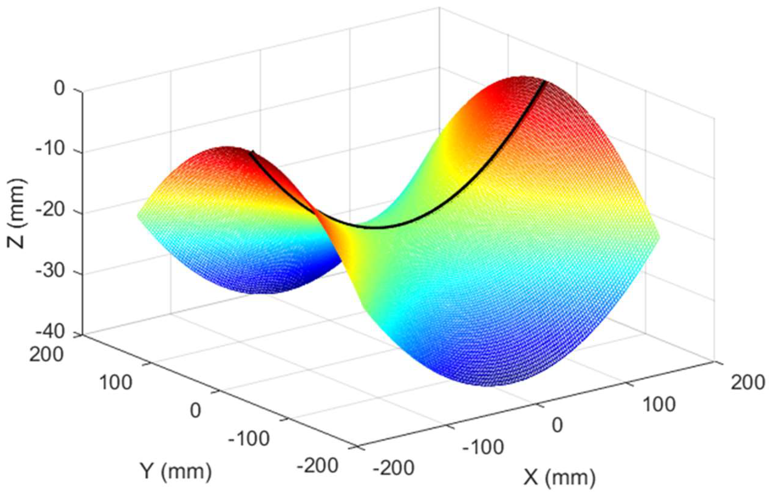
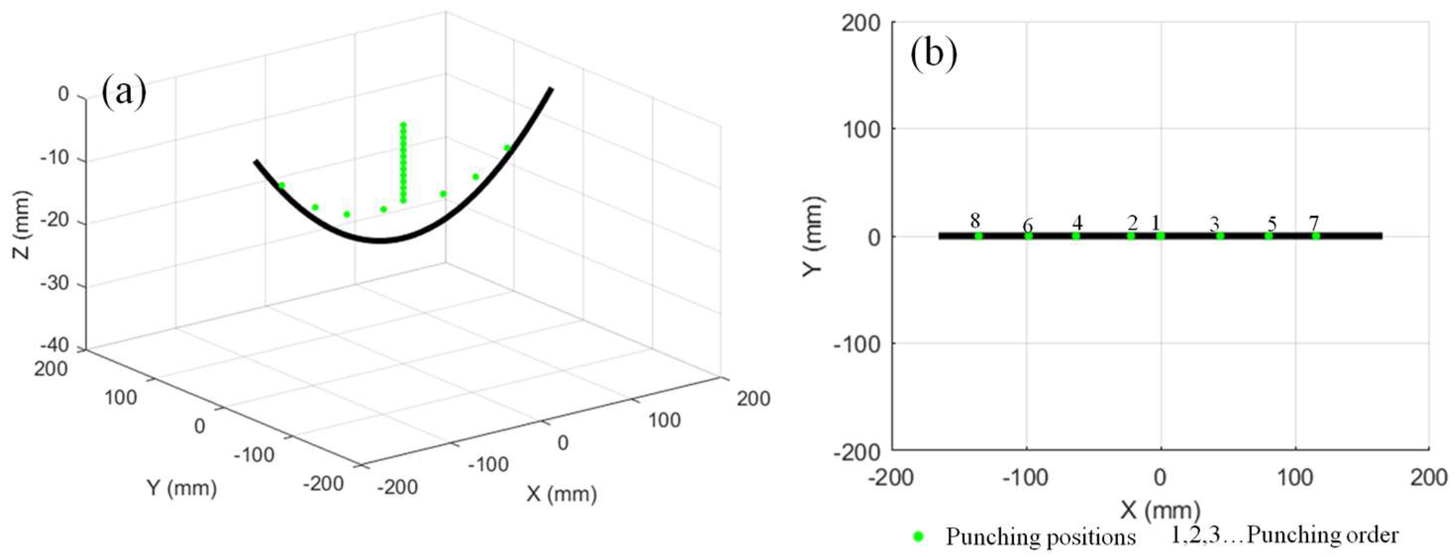
First of all, the design shape and machining track of forming the one-way curvature plate are the same as that of forming the sail-shaped plate with sequential bending strategy, as shown in Figure 6 and Figure 7. The experimental diagram of the machining process is shown in Figure 10a. The design shape of the saddle-shaped plate and the second curvature forming track are shown in Figure 11 and Figure 12, respectively.
The processing experiment figure is shown in Figure 13. Due to the two curvature directions of the saddle plate in the opposite direction, as after forming in one curvature direction, it is difficult to form the plate in the second reverse direction, so the pre-stressed heat auxiliary gradual bending technique is applied here, as illustrated in Figure 13. The punch first presses downward along the minimum energy loading path, applying a pre-stress to the metal plate at the stamping point. Subsequently, linear heating is applied to both sides of the plate to achieve the saddle-shaped bending formation.

3.3. Simulation

At present, finite element simulation has been widely used to study the deformation behavior of metal sheets in various forming processes. The numerical simulation of incremental bending is based on the general commercial finite element software. In order to obtain accurate simulation results, it is very important to select appropriate finite element analysis method. Generally speaking, dynamic explicit method and static implicit method are used in stamping process analysis and springback process analysis. In this process, the feed speed of the stamping tool is 100 mm/min, and the bending process can be seen as quasi-static deformation. In addition, the gradual bending process requires a multi-step continuous stamping and springback process, so it is very inconvenient to change the finite analysis method again and again. In addition, due to the limited constraints, the simulation of incremental bending process by dynamic explicit method has significant dynamic effects. Therefore, static implicit method is adopted in the whole simulation process.
The elastoplastic thermodynamic coupled constitutive model is used in the simulation study. The yield behavior of low carbon steel Q235 was described by Von Mises isotropic yield criterion [24]. It is defined as:
σ e f f = 1 2 σ 1 σ 2 2 + σ 2 σ 3 2 + σ 3 σ 1 2
or equivalently in terms of deviatoric stress components:
σ e f f = 3 2 s i j s i j
where σ 1   σ 2   σ 3 are the principal stresses, and s i j is the deviatoric stress tensor.
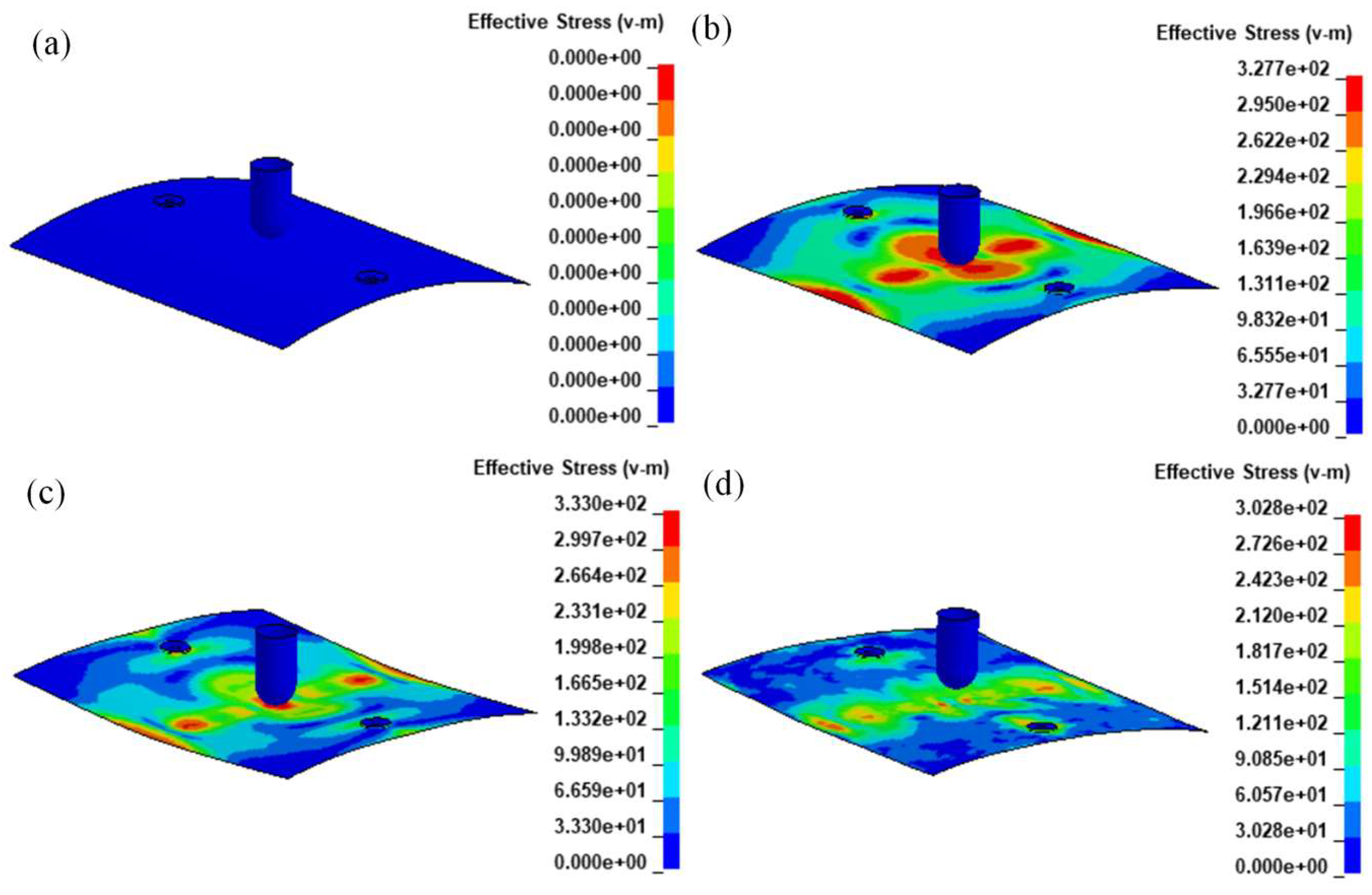
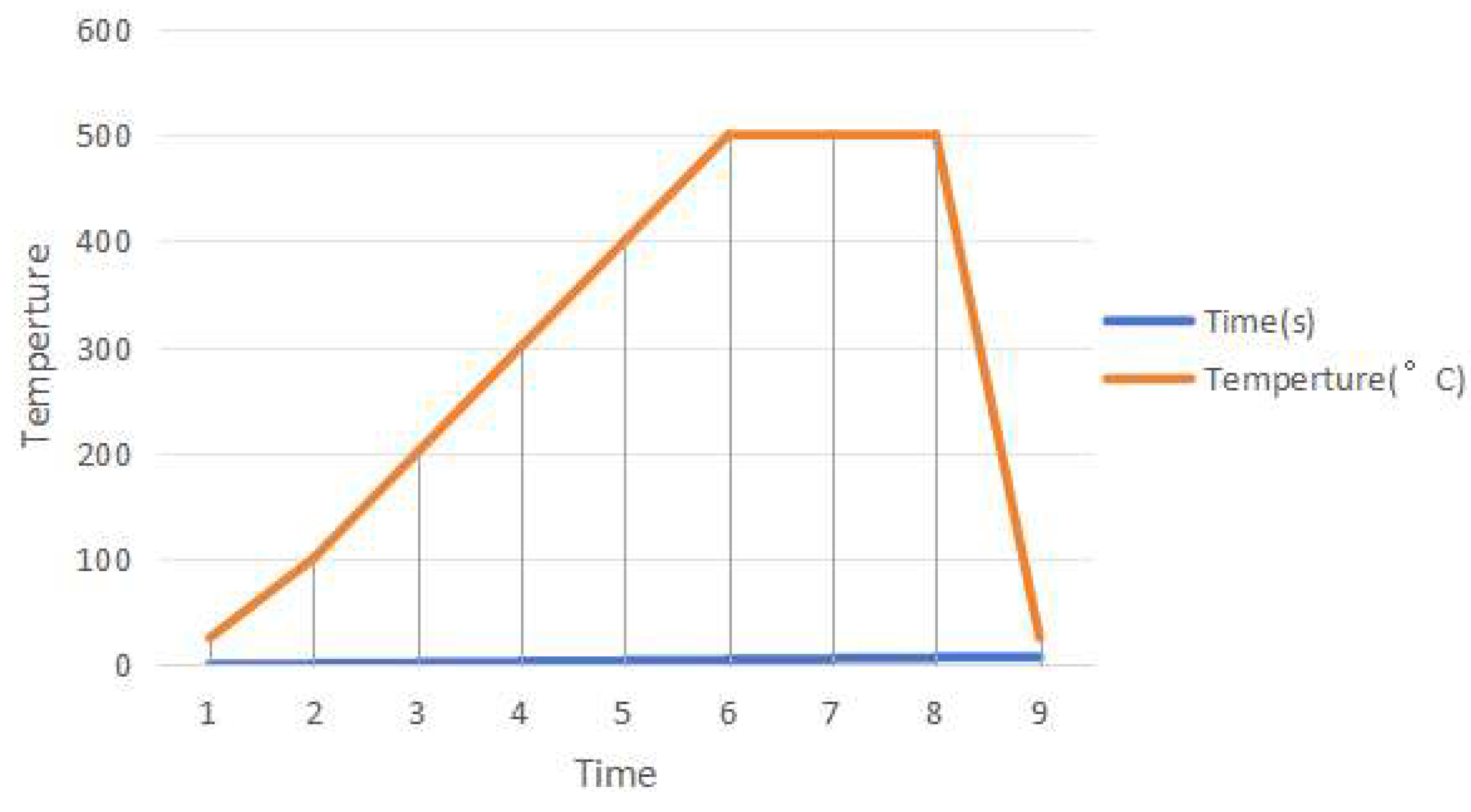
The fully integrated shell element is used to generate mesh. There is no hourglass control in the simulation because the hourglass can be completely eliminated using the fully integrated element. Coulomb’s friction law is used to describe the friction behavior between tool and metal plate, with a friction coefficient of 0.2. The metal plate can rotate around the supporting center of mass with a rotation radius of 42 mm. In addition, the one-way face-to-face contact method was chosen to define the contact between the plate and the punch. The mechanical and thermal properties of low carbon steel at different temperatures are shown in [25]. At the same time, a rigid body model was used to describe the punch and support. Due to the quasi-static nature of the process (punch speed: 2–5 mm/s), strain rate effects are considered negligible for Q235 steel at elevated temperatures, and thus not included in the current material model. As shown in Figure 14, the numerical model consists of a metal plate, a punch with a diameter of 50 mm, and two rotatable support columns. The size of all metal slats in numerical simulation and experiment is the same (330 × 330 × 3 mm). Taking saddle-shaped plate forming simulation as an example, the whole simulation process includes multiple punching steps; each punching step includes: initial state, stamping state, heating state, and springback state. As shown in Figure 15, the heating process is realized by adding temperature–time curve on the mesh.

4. Results and Discussion

4.1. Comparative Study on Sequential Forming Process of Double-Curvature Plates

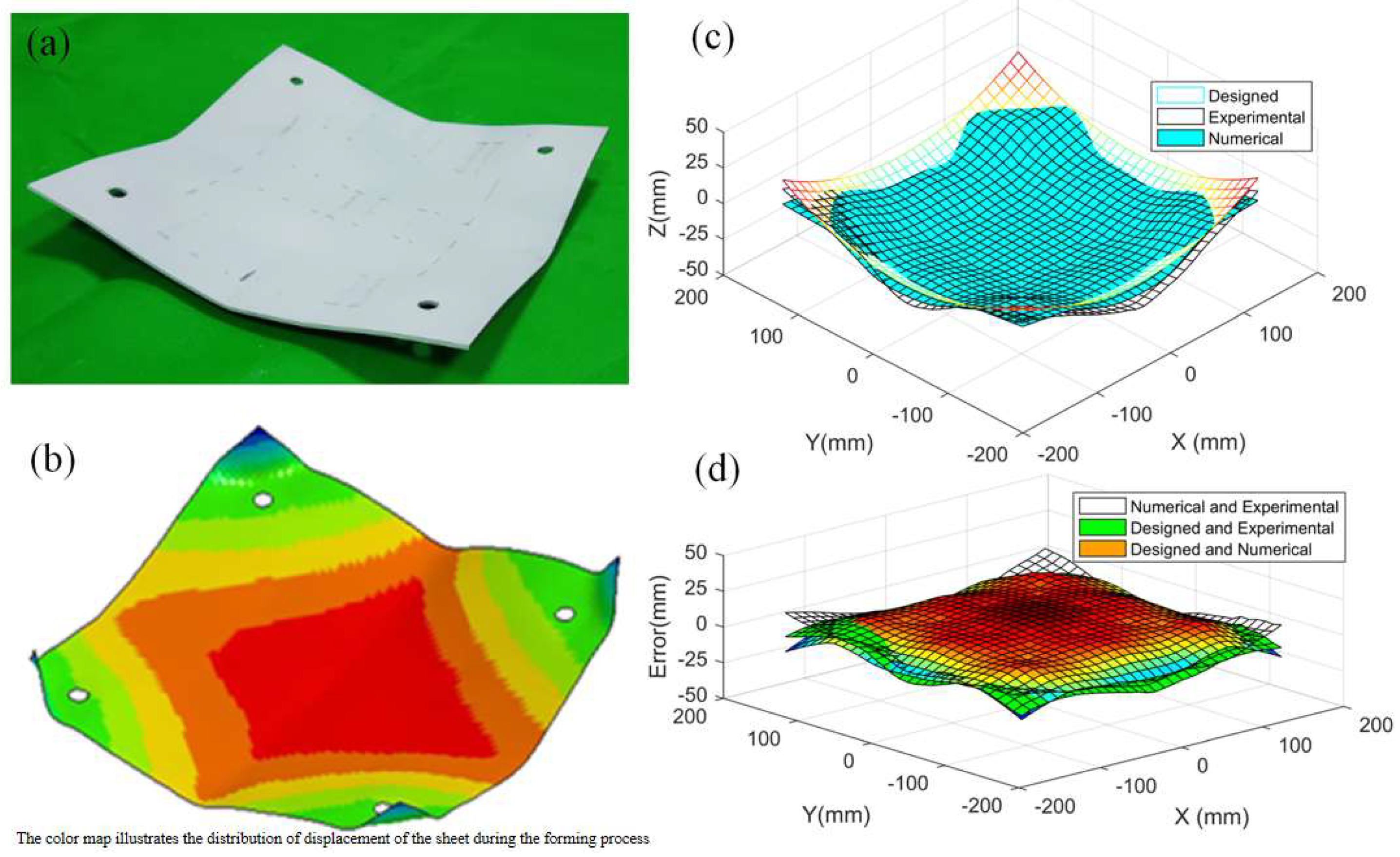
The comparative results of experimental tests, simulation outcomes, and design targets for the successively formed sail-shaped plate in dual-curvature directions are presented in Figure 16. Figure 16a indicates no plastic hinges, wrinkles, or indentations in the formed plate, with visible black linear traces resulting from the inevitable removal of contrast-enhancing coating material during stamping-induced bending deformation. Figure 16a,b demonstrate excellent consistency between experimental and simulated forming results. Simulations reveal warping at the plate corners, attributable to simplified boundary conditions where supports were modeled with centroidal moment of inertia rotations only. Excluding corner effects, this simplification negligibly impacts forming accuracy in other regions and thus maintains overall simulation validity. Corner warping was disregarded during comparative analysis.
Figure 16c quantifies an average presenting error of 4.6% between simulation and experimental results: 4.1% between experimental and design targets, and 5% between simulation and design targets. The maximum error (approximately 13%) occurs at the plate corners.
During the forming process, it was found that when using this method to form sail-shaped plates, as the bending curvature increases, the bending strain and stress accumulate, leading to an increased strain hardening effect, which makes it difficult to form in the other direction. Therefore, this method is only suitable for the forming of plates with small curvatures. For plates with large curvatures, an alternative bending forming strategy should be adopted, such as multi-directional incremental forming [26].
The comparative results of experimental tests, simulation outcomes, and design targets for the successively formed saddle-shaped plate in two curvature directions are shown in Figure 17. Figure 17a indicates no plastic hinges, wrinkles, or indentations formed in the shaped plate. Figure 17a,b demonstrate strong consistency between experimental and simulation forming results. Figure 17c reveals an average presenting error of 8.3% between simulation and experimental results, 8.6% between experimental and design targets, and 7.6% between simulation and design targets. The maximum error (approximately 16.6%) occurs at the mid-region of the second curvature direction. This is attributed to work hardening after forming the first curvature, which significantly increases the difficulty of forming the opposing curvature in the saddle-shaped plate. Consequently, forming the second curvature requires bending at both edges while demanding greater curvature at the center.
This sequential approach is inefficient: after forming the first curvature, the single-curvature plate must be disassembled and re-fixtured in the opposite orientation, prolonging forming time. Thus, simultaneous forming strategies for both curvature directions should be prioritized when processing saddle-shaped metal plates.

4.2. Comparison of Results for Forming Double-Curvature Plates Using Different Methods

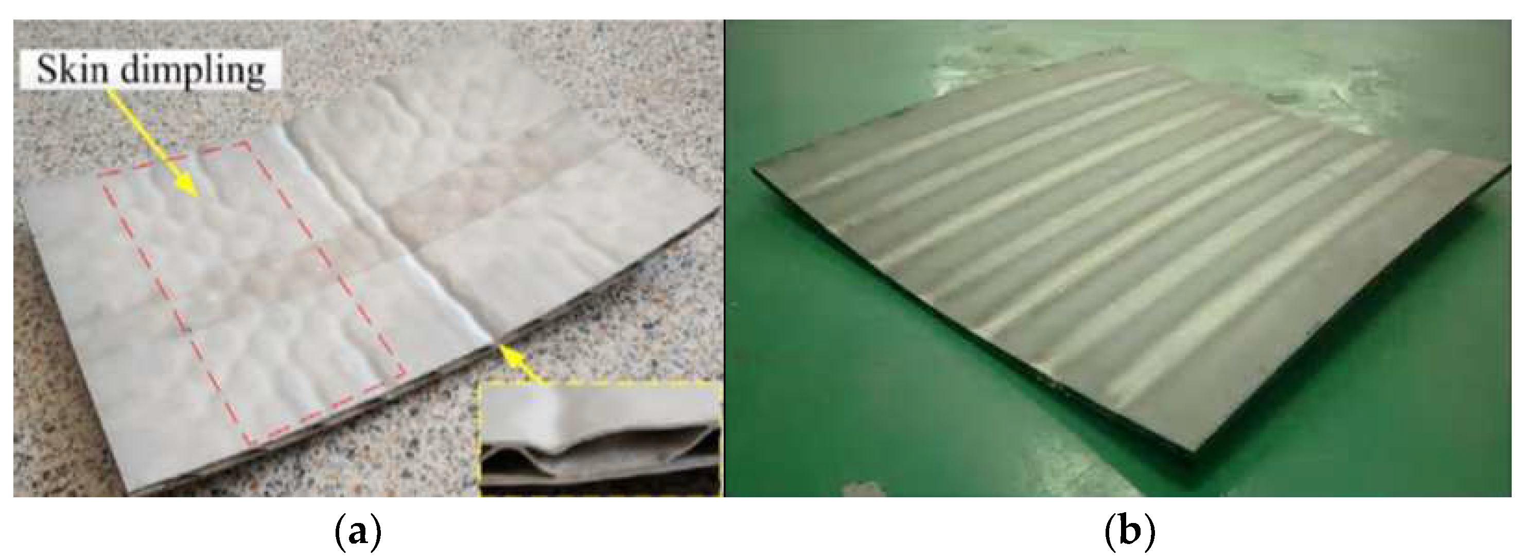
Figure 18 shows sail-shaped plate workpieces formed by the multi-point forming method [4,5]. It can be observed that although the formed curvatures of both workpieces are very small, obvious wrinkles and stamping dents are present, severely affecting the surface quality and forming accuracy of the workpieces. Therefore, the parts formed by multi-point forming do not meet application requirements. Figure 19a,b show drape-shaped plate workpieces formed by the segmented roll forming and continuous flexible roll forming methods [6,7,10], respectively. Although these two workpieces exhibit no wrinkles or stamping dents, the segmented roll-formed sail-shaped plate has a thickness of 8 mm and achieves a curvature radius of only 3600 mm. In contrast, the continuously flexible roll-formed sail-shaped plate has a thickness of merely 1 mm and achieves a curvature radius of 500 mm. No other methods for forming sail-shaped plates have been reported in the literature.
As shown in Figure 20a,b, these are saddle-shaped plates formed using multi-point forming and line heating methods [27,28], respectively. It can be observed that the formed curvatures are very small, with curvature radii of 1000 mm and 5340 mm, respectively. However, the multi-point formed workpiece exhibits obvious wrinkles and stamping dents, severely affecting the surface quality and forming accuracy. Therefore, the parts formed by multi-point forming do not meet application requirements. Additionally, the curvature and forming efficiency achieved by line heating do not satisfy application demands either.
Figure 21a,b show saddle-shaped plates formed by segmented roll sets and continuous flexible roll forming methods [6,7,10]. Although these two workpieces do not have wrinkles or stamping dents on their surfaces, the segmented roll-formed saddle-shaped plate has a thickness of 8 mm and a very small forming curvature radius of only 3000 mm. In contrast, the continuously flexible roll-formed saddle-shaped plate has a thickness of merely 1 mm and achieves a curvature radius of 452 mm.
In summary, comparing all the above forming results, it is evident that the heat-assisted incremental bending with minimum energy loading trajectory for forming saddle-shaped and drape-shaped plates offers significant advantages. This method not only achieves high forming efficiency but also ensures excellent surface quality.

5. Conclusions

In the present paper, the theoretical and simulation models of deformation and springback phenomenon for double-curvature metal plates were established. Experiments were carried out under different conditions, and the influences of heating temperature and stamping positions on the deformation behavior of the metal plates were investigated. The one point bending deformation and springback law of metal plates for heat-assisted incremental bending process at different temperatures and punching positions are obtained first, and then the forming of double-curvature plates was studied by combining the bending trajectory and springback law [25]. The double-curvature plates are obtained by simulation and experiment methods. The main observations are summarized below.
Theoretical and finite element models for deformation and springback in double-curvature metal plates were successfully established and experimentally validated.
Heating temperature significantly affects deformation behavior: at 500 °C, springback is almost eliminated, enabling high-precision forming.
Stamping position influences forming force magnitude; local heating can significantly reduce the forming force compared to cold forming.
The minimum energy loading trajectory reduces forming force and completes complex saddle-shaped plates within 20 min, significantly improving efficiency.
Experimental and simulation results show an average shape error of less than 3 mm, confirming the accuracy and reliability of the process.
Auxiliary support and localized heating effectively improve curvature development in the weak direction for asymmetric double-curvature forming.
The method enables tooling-free, flexible fabrication of complex 3D plates, with promising applications in shipbuilding and construction.
This work demonstrates the potential of high-frequency heating in improving the formability and precision of medium-thickness double-curved plates. However, the current findings are primarily geometric and process-oriented. Future studies should include systematic characterization of mechanical property retention, such as Vickers hardness mapping and tensile testing of extracted coupons, to fully validate the structural integrity of the formed components. Additionally, microstructural analysis (e.g., grain evolution, precipitation behavior) could provide deeper insights into the thermomechanical effects of the process.
The use of a minimum energy-based loading path, derived from a beam-segmented model, promotes smooth deformation and reduces path dependency. As a result, minor misalignments in the first bending stage are expected to have limited influence on the second bending. However, a systematic evaluation of process tolerance to path deviations is recommended for future work.

Author Contributions

B.W.: Writing—Original Draft, Software, Methodology, Investigation, Formal Analysis, Data Curation, Conceptualization. F.Z.: Writing—Review and Editing, Original Draft, Methodology. Z.C.: Resources, Investigation, Formal Analysis. B.Y.: Writing—Review and Editing, Writing—Original Draft, Supervision, Resources, Methodology. All authors have read and agreed to the published version of the manuscript.

Funding

This research was funded by Guangzhou Science and Technology Bureau Projects (No. SL2022A04J00030) and SIAT-CUHK Joint Laboratory of Precision Engineering, Shenzhen High-tech Zone Development Special Plan Innovation Platform Construction Project, the proof of concept center for high precision and high resolution 4D imaging, High-Level Talent Project (No. 2022-gc-07), and the Open Project Program (No. 20221223).

Data Availability Statement

The original contributions presented in the study are included in the article. Further inquiries can be directed to the corresponding authors.

Conflicts of Interest

The authors declare no conflict of interest.

References

  1. Shin, J.G.; Woo, J.H. Analysis of heat transfer between the gas torch and the plate for the application of line heating. J. Manuf. Sci. Eng. 2003, 125, 794–800. [Google Scholar] [CrossRef]
  2. Shin, J.G.; Lee, J.M.; Nam, J.H. An efficient algorithm for measurement and comparison of large-scale hull pieces in the line-heating process. J. Ship Prod. 2004, 20, 60–67. [Google Scholar] [CrossRef]
  3. Li, M.Z.; Cai, Z.Y.; Sui, Z.; Yan, Q. Multi-point forming technology for sheet metal. J. Mater. Process. Technol. 2002, 129, 333–338. [Google Scholar] [CrossRef]
  4. Liu, Y.J.; Li, M.Z.; Ju, F.F. Research on the process of flexible blank holder in multi-point forming for spherical surface parts. Int. J. Adv. Manuf. Technol. 2017, 89, 2315–2322. [Google Scholar] [CrossRef]
  5. Qu, E.H.; Li, M.Z.; Li, R.; Zhao, L.; Yi, Z. Inhibitory effects of a flexible steel pad on wrinkling in multi-point die forming. Int. J. Adv. Manuf. Technol. 2018, 95, 2413–2420. [Google Scholar]
  6. Shim, D.S.; Yang, D.Y.; Kim, K.H.; Han, M.; Chung, S. Numerical and experimental investigation into cold incremental rolling of doubly curved plates for process design of a new LARS (line array roll set) rolling process. CIRP Ann. 2009, 58, 239–242. [Google Scholar] [CrossRef]
  7. Shim, D.S.; Yang, D.Y.; Kim, K.H.; Chung, S.; Han, M. Investigation into forming sequences for the incremental forming of doubly curved plates using the line array roll set process. Int. J. Mach. Tools Manuf. 2010, 50, 214–218. [Google Scholar] [CrossRef]
  8. Cai, Z.Y.; Li, L.L.; Wang, M.; Li, M.-Z. Process design and longitudinal deformation prediction in continuous sheet metal roll forming for three-dimensional surface. Int. J. Precis. Eng. Manuf. 2014, 15, 1889–1895. [Google Scholar] [CrossRef]
  9. Cai, Z.Y.; Li, M.Z.; Lan, Y.W. Three-dimensional sheet metal continuous forming process based on flexible roll bending: Principle and experiments. J. Mater. Process. Technol. 2012, 212, 120–127. [Google Scholar] [CrossRef]
  10. Li, R.J.; Li, M.Z.; Qiu, N.J.; Cai, Z.-Y. Surface flexible rolling for three-dimensional sheet metal parts. J. Mater. Process. Technol. 2014, 214, 380–389. [Google Scholar] [CrossRef]
  11. Kim, J.; Na, S.J. Development of irradiation strategies for free curve laser forming. Opt. Laser Technol. 2003, 35, 605–611. [Google Scholar] [CrossRef]
  12. Kim, J.; Na, S.J. Feedback control for 2D free curve laser forming. Opt. Laser Technol. 2005, 37, 139–146. [Google Scholar] [CrossRef]
  13. Yang, L.J.; Wang, M.L.; Wang, Y.; Chen, Y. Dynamic analysis on laser forming of square metal sheet to spherical dome. Int. J. Adv. Manuf. Technol. 2010, 51, 519–539. [Google Scholar] [CrossRef]
  14. Safari, M.; Farzin, M. Experimental investigation of laser forming of a saddle shape with spiral irradiating scheme. Opt. Laser Technol. 2015, 66, 146–150. [Google Scholar] [CrossRef]
  15. Chakraborty, S.S.; More, H.; Nath, A.K. Laser forming of a bowl shaped surface with a stationary laser beam. Opt. Lasers Eng. 2016, 77, 126–136. [Google Scholar] [CrossRef]
  16. Hong, S.; Zhou, W.T.; Wang, H. Laser forming of doubly curved plates using minimum energy principle and comprehensive strain control. Int. J. Mech. Sci. 2018, 14, 542–552. [Google Scholar]
  17. Guan, Y.J.; Sun, S.; Zhao, G.Q.; Luan, Y.G. Finite element modeling of laser bending of pre-loaded sheet metals. J. Mater. Process. Technol. 2003, 142, 400–407. [Google Scholar]
  18. Yao, Z.Q.; Hong, S.; Shi, Y.J.; Hu, J. Numerical study on laser forming of metal plates with pre-loads. Comput. Mater. Sci. 2007, 40, 27–32. [Google Scholar] [CrossRef]
  19. Liu, J.; Sun, S.; Guan, Y.J. Numerical investigation on the laser bending of stainless steel foil with pre-stresses. J. Mater. Process. Technol. 2009, 209, 1580–1587. [Google Scholar] [CrossRef]
  20. Gisario, A.; Barletta, M.; Venettacci, S.; Veniali, F. Laser-assisted bending of sharp angles with small fillet radius on stainless steel sheets: Analysis of experimental set-up and processing parameters. Lasers Manuf. Mater. Process. 2015, 2, 57–73. [Google Scholar] [CrossRef]
  21. Gisario, A.; Barletta, M.; Venettacci, S. Improvements in springback control by external force laser-assisted sheet bending of titanium and aluminum alloys. Opt. Laser Technol. 2016, 86, 46–53. [Google Scholar] [CrossRef]
  22. Gisario, A.; Barletta, M.; Venettacci, S.; Veniali, F. External force-assisted Laser Origami (LO) bending: Shaping of 3D cubes and edge design of stainless steel chairs. J. Manuf. Process. 2015, 18, 159–166. [Google Scholar] [CrossRef]
  23. Dang, X.B.; He, K.; Li, W.; Zuo, Q.; Du, R. Incremental bending of three-dimensional free form metal plates using minimum energy principle and model-less control. J. Manuf. Sci. Eng. 2017, 139, 071009. [Google Scholar] [CrossRef]
  24. Hill, R. The Mathematical Theory of Plasticity; Oxford University Press: Oxford, UK, 1998. [Google Scholar]
  25. Gendron, M.; Hazel, B.; Boudreault, E.; Champliaud, H.; Pham, X.-T. Coupled thermo-electromagnetic model of a new robotic high-frequency local induction heat treatment system for large steel components. Appl. Therm. Eng. 2019, 150, 372–385. [Google Scholar] [CrossRef]
  26. Wei, B.; Zhang, F.F.; He, K.; Li, Z.; Du, R. Deformation and Springback Behavior of Sheet Metal With Convex-Shaped Surfaces in Heat-Assisted Incremental Bending Process Based on Minimum Energy Method. J. Manuf. Sci. Eng. 2023, 145, 031003. [Google Scholar] [CrossRef]
  27. Liang, X.B.; Cai, Z.Y.; Zhang, X.; Gao, J.-X. Plastic forming of the doubly curved surfaces of sandwich plates with bi-directionally trapezoidal cores of different sizes. Thin-Walled Struct. 2020, 146, 478–488. [Google Scholar] [CrossRef]
  28. Seong, W.J.; Jeon, Y.C.; Na, S.J. Ship-hull plate forming of saddle shape by geometrical approach. J. Mater. Process. Technol. 2013, 213, 1885–1893. [Google Scholar] [CrossRef]
Figure 1. Type of double-curvature plate: (a) sail plate, (b) saddle plate.
Metals 15 01124 g001
Figure 2. Schematic illustration of forming double-curvature plates by sequential bending strategy.
Metals 15 01124 g002
Figure 3. Schematic illustration of the heat-assisted incremental bending process.
Metals 15 01124 g003
Figure 4. Schematic illustration of discretized strips in x and y directions: (a) sail plate, (b) saddle plate.
Metals 15 01124 g004
Figure 5. Experimental setup of the heat-assisted incremental bending process.
Metals 15 01124 g005
Figure 6. Design shape of single-curvature plate.
Metals 15 01124 g006
Figure 7. Loading trajectory of primary curvature forming: (a) three-dimensional schematic diagram of stamping point, (b) two-dimensional schematic diagram of punching sequence.
Metals 15 01124 g007
Figure 8. Target shape of the sail plate.
Metals 15 01124 g008
Figure 9. Loading trajectory of secondary curvature forming: (a) three-dimensional schematic diagram of stamping point, (b) two-dimensional schematic diagram of punching sequence.
Metals 15 01124 g009
Figure 10. Experimental figure of sequentially bending forming sail plate: (a) the primary curvature forming, (b) the secondary curvature forming.
Metals 15 01124 g010
Figure 11. Secondary curvature shape of saddle plate.
Metals 15 01124 g011
Figure 12. Secondary curvature loading trajectory of saddle plate: (a) three-dimensional schematic diagram of stamping point, (b) two-dimensional schematic diagram of punching sequence.
Metals 15 01124 g012
Figure 13. Experimental figure of forming in the second direction of curvature.
Metals 15 01124 g013
Figure 14. Numerical simulation models at various states; (a) initial state, (b) punching state, (c) heating state, (d) springback state.
Metals 15 01124 g014
Figure 15. Adding temperature–time curve.
Metals 15 01124 g015
Figure 16. Sequentially bending forming sailed plates: (a) the experimental sample, (b) the simulation result, (c) comparison of experimental, simulation, and design objective results, (d) error distribution between experimental, simulation, and design objectives, respectively.
Metals 15 01124 g016
Figure 17. Sequentially bending forming saddle plates: (a) the experimental sample, (b) the simulation result, (c) comparison of experimental, simulation, and design objective results, (d) error distribution between experimental, simulation, and design objectives, respectively.
Metals 15 01124 g017
Figure 18. Multi-point forming of sail-shaped plate workpiece, Reprinted from Refs. [4,5].
Metals 15 01124 g018
Figure 19. Sail-shaped workpiece formed by flexible roller, Reprinted from Refs. [6,7,10]. (a) the segmented roll forming, (b) the continuous flexible roll forming.
Metals 15 01124 g019
Figure 20. Multi-point and line heating forming of saddle plate workpiece. (a) the multi-point forming, Reprinted from Ref. [27], (b) the line heating, Reprinted from Ref. [28].
Metals 15 01124 g020
Figure 21. Saddle plate workpiece formed by flexible roller, Reprinted from Refs. [6,7,10]. (a) the segmented roll forming, (b) the continuous flexible roll forming.
Metals 15 01124 g021
Disclaimer/Publisher’s Note: The statements, opinions and data contained in all publications are solely those of the individual author(s) and contributor(s) and not of MDPI and/or the editor(s). MDPI and/or the editor(s) disclaim responsibility for any injury to people or property resulting from any ideas, methods, instructions or products referred to in the content.