Article

Research on the Solidification Structure, Properties and Composition Segregation of GCr15 Bearing Steel Under Double-Electrode Regulation

1
School of Materials and Metallurgy, University of Science and Technology Liaoning, Anshan 114051, China
2
Technical Support Center for Prevention and Control of Disastrous Accidents in Metal Smelting, University of Science and Technology Beijing, Beijing 100083, China
*
Authors to whom correspondence should be addressed.
Metals 2025, 15(10), 1086; https://doi.org/10.3390/met15101086
Submission received: 30 July 2025 / Revised: 20 September 2025 / Accepted: 25 September 2025 / Published: 29 September 2025
(This article belongs to the Special Issue Green Super-Clean Steels)

Abstract

To explore the influence of double-electrode regulation technology on the solidification microstructure and properties of GCr15 bearing steel, the double-electrode insertion process was employed in this study, combined with metallographic analysis, mechanical property testing, and electron probe composition characterization. We analyzed the mechanisms of solidification microstructure evolution and mechanical property improvement, as well as the composition segregation control effect, of GCr15 steel under double-electrode regulation. The results show that the double-electrode technology significantly refines the microstructure and improves the internal quality of the ingot by optimizing the temperature field and electromagnetic field distribution in the molten pool and enhancing the internal flow of the melt. The tensile strengths in the upper and middle parts were increased by 84.6% and 29.6%, respectively, which can be attributed to the uniform distribution of carbides at the grain boundaries and the reduction of segregation. Composition analysis indicates that the macroscopic segregation index of C element was decreased under the dual-electrode process. This research provides a theoretical basis and process optimization direction for the high-quality preparation of high-carbon chromium bearing steel.

1. Introduction

Bearing steel is usually used as a manufacturing material for balls, rollers, and bearing rings [1]. GCr15 bearing steel is a common and widely used high C and Cr bearing steel grade. To endow it with higher mechanical properties, appropriate amounts of C and Cr elements are usually added to strengthen the performance, but serious element segregation is caused during the solidification of the ingot. Especially, the segregation of C element results in the formation of a large number of reticular and granular carbides [2,3,4]. Attempts have been made by scholars to alleviate the carbide defects caused by segregation through homogenization treatment, but they are still difficult to remove, which greatly reduces the comprehensive performance of bearing steel [5]. When bearing parts are in operation, the inner and outer rings of the bearing and the rolling elements are subjected to high-frequency alternating stress loads. Due to the harsh working conditions of bearings, strict requirements are imposed on their uniform hardness, wear resistance, high elastic limit, high contact fatigue strength, and corrosion resistance [6,7]. It has been found that the segregation of C elements is caused by selective crystallization during solidification [8]. Therefore, how to reduce the segregation of C elements during the solidification of GCr15 bearing steel is the key to solving the application bottleneck.
Electromagnetic stirring (EMS) is regarded as one of the effective methods to eliminate the centerline segregation of continuous casting billets. It exhibits multiple excellent metallurgical functions, such as refining grain size, improving the fluidity of residual liquid phase, and homogenizing the solute-rich liquid [9,10]. As early as the 1920s, Mcneill [11] discovered that the degree of segregation and element distribution in the solidification structure were related to the internal flow of the molten metal, and the solidification structure was improved through electromagnetic stirring. In 1948, the world’s first electromagnetic stirrer was applied to electric arc furnace steelmaking. Rankinberg pointed out that adding an alternating electromagnetic field during solidification could refine the internal structure of steel ingots. In the 1990s, China independently designed an electromagnetic stirring system in the secondary cooling zone, and smooth-surfaced and fine-grained thick slab structures were obtained after treatment, leading to the improvement of mechanical properties. EMS technology improves the processing performance of cast billets and surface quality and has been widely applied. Tomar N et al. [12] found that the solidification structure of austenitic stainless steel treated by electromagnetic field was refined, with central porosity and shrinkage cavities reduced and the temperature gradient at the solidification front lowered. Cha PR [13] established a three-dimensional mathematical model of fluid flow in the electromagnetic casting mold based on the finite element method and the finite volume method. It was found by Tang et al. [14] that dendrites were broken under the action of magnetic force during solidification, and the broken dendrite fragments moved in the direction of the electromagnetic force, indicating that the electromagnetic field has a significant impact on the solidification structure. Cai et al. [15] proposed the principle of electromagnetic removal of inclusions, where inclusions that do not react with the magnetic field are pushed in the opposite direction of the electromagnetic force by applying a direct current magnetic field to the metal. Through computational analysis, Bao et al. [16] found that magnetic field, oscillation, and Joule heating all affect the nucleation rate of the solidification structure and analyzed the influence of low-voltage pulsed magnetic field on the solidification structure of manganese alloys. It was also found by Li et al. [17] that applying a strong static magnetic field during the solidification process could increase the undercooling of the molten metal and effectively inhibit the formation of secondary dendrites. The continuous exchange of steel liquid between the core and the outside can make the composition and temperature uniform, achieving the effect of grain refinement. The broken dendrites become nuclei, promoting heterogeneous nucleation, and causing forced convection in the liquid metal. Additionally, the convection caused by electromagnetic stirring can break the dendrite arms formed, and the broken dendrite walls at the initial solidification shell are carried into the interior of the cast billet for recrystallization, refining the grains and inhibiting dendrite growth to improve the quality of the cast billet. During the stirring process, internal inclusions in the steel liquid can float up and no external impurities are introduced.
In recent years, numerical simulation techniques have demonstrated reliable predictive capabilities for fluid flow, electromagnetic fields, heat transfer, and mass transport phenomena. Notably, several critical technologies, including heat transfer during solidification, mold-filling flow patterns, and coupled thermo-fluid dynamics, have progressed from theoretical development to practical implementation [18]. As early as 1962, Forsund in Denmark pioneered the application of finite difference methods for heat transfer calculations during solidification processes, particularly for temperature field computations. However, at that time, the fundamental understanding of multi-physics coupling mechanisms (including magnetic-thermal-mechanical interactions) remained incomplete, and systematic knowledge of these coupled phenomena was lacking. Subsequently, Zhang et al. [19] developed a comprehensive three-dimensional numerical model for ingot mold-filling and solidification processes, demonstrating significant advantages over simplified models. Their work systematically analyzed how gating system design influences both mold-filling predictions and final ingot quality. Methodologies for utilizing electromagnetic fields to eliminate centerline segregation and improve internal quality in steel ingots have been extensively investigated through both numerical simulations and industrial trials in current research. It has been demonstrated by Li et al. [20] that the application of electromagnetic fields during solidification has garnered significant research attention over the past decade. Their findings revealed that Lorentz force-induced effects can effectively modify heat transfer, mass transport, and momentum transfer processes, leading to substantial refinement of solidification microstructures. Through numerical simulations, Wang et al. [21] investigated the solidification behavior and crystallization processes of Cr-Co-Mo-Ni bearing steel during electroslag remelting. Their results indicated that controlled adjustment of cooling intensity significantly enhances grain refinement and promotes denser, more homogeneous solidification structures, thereby improving microstructural uniformity and reducing material property variations. In a complementary study, the effects of electromagnetic stirring on molten steel solidification were numerically analyzed by Wang et al. [22]. Their simulations confirmed that electromagnetic stirring profoundly influences molten steel flow patterns and heat transfer characteristics, ultimately resulting in improved internal microstructure of steel ingots.
An electric field is introduced in this study based on the double electrode method, aiming to regulate the internal quality of steel ingots by applying an external current. By combining experiments with numerical simulations, the influence laws of the electric field on the flow field, temperature field, mass and heat transfer, etc., during the solidification process of steel ingots are explored, and the mechanism by which the electric field affects the internal quality of steel ingots is clarified. The research results provide guidance for the production of high-quality steel ingots.

2. Experimental Methods and Numerical Simulation

2.1. Experimental Materials and Methods

Industrialized GCr15 steel products were utilized in this experiment, whose composition is shown in Table 1. The steel product obtained from plant is remelted and prepared the ingot sample. The alloy was melted in a 60 kW medium-frequency induction furnace. A steel bar weighing approximately 25 kg was placed in a magnesia crucible and heated to melting in the melting furnace. Then, 70 g of aluminum strips were inserted to deoxidize, and protective slag was covered. The protective slag is consisting of CaO, SiO2, and Al2O3 (Macklin Inc., Shanghai, China). The protective slag isolates the air through the melting slag layer to prevent oxidation, and the powder layer achieves insulation and heat preservation. Subsequently, a double-electrode device was placed above the crucible. After the double electrodes were powered on, the lifting platform was lowered to insert the graphite electrodes into the alloy liquid surface by 30 mm, and direct current was applied. Initially, 150 A of direct current was applied for 10 min; after an 8 min pause, 150 A of direct current was applied again for 5 min; then the current was increased to 350 A and maintained for 3 min. After the power was turned off, the electrodes were withdrawn, and protective slag was reapplied until the steel liquid completely cooled. The reason for applying a smaller current first and then a larger one was to prevent slag entrainment. The experimental setup is shown in Figure 1.

2.2. Numerical Simulation

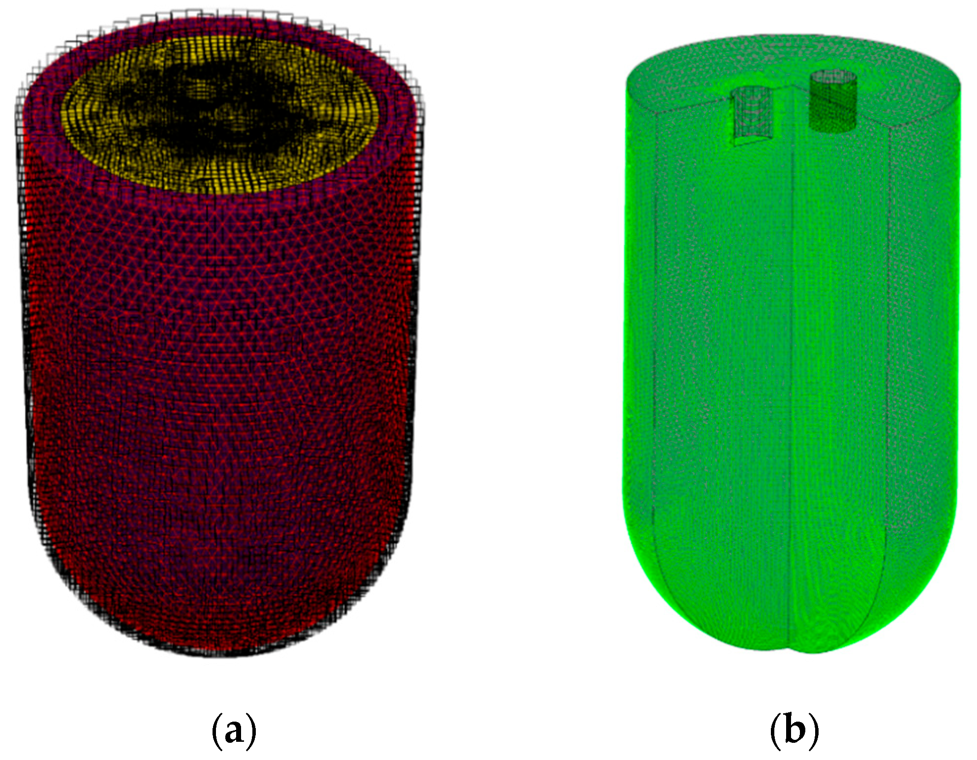
ANSYS 14.5 finite element analysis was used in this study to simulate the convection, heat transfer, and mass transfer processes in the melt under two experimental conditions. The model was established based on the size of the experimental ingot, with a diameter of 130 mm and a height of 230 mm. The depth of the inserted electrode was 5 mm and the distance between the electrodes was 10 mm. The mesh division is shown in Figure 2.
The model is composed of two parts: the ingot mold and the melt. Three-dimensional modeling is adopted, with dimensions designed in equal proportion to the experimental dimensions. By means of the finite element method, the coupling process between the electromagnetic field and the melt flow field is numerically simulated, and the flow field behavior under the action of electric current is calculated. As shown in Figure 2, the casting model is divided into a mesh consisting of 250,000 hexahedral elements. To ensure the accuracy of the simulation, mesh refinement is performed in the region where the electrode is inserted.
To reduce computational costs, the following assumptions are made in the computational process:
  • Conservation of flux is assumed at the phase interface;
  • During the simulation, the alloy melt is assumed to remain a single-phase, stable, and continuous incompressible fluid;
  • The influence of the Joule heating effect on electrode conductivity is neglected, and the heat transfer process is not considered.

2.3. Microstructure Observation

For microstructural analysis, the specimens were sequentially ground using 200#, 400#, 800#, 1000#, 1500#, and 2000# abrasive papers, followed by mechanical polishing. The polished samples were then etched with a 4% nitric acid-alcohol solution to reveal microstructural features. The microstructure, precipitate morphology, and precipitate composition of the sample were observed using an EVO MA 10 Zeiss scanning electron microscope (SEM) (Carl Zeiss AG, Oberkochen, Germany).

2.4. Composition Segregation Test

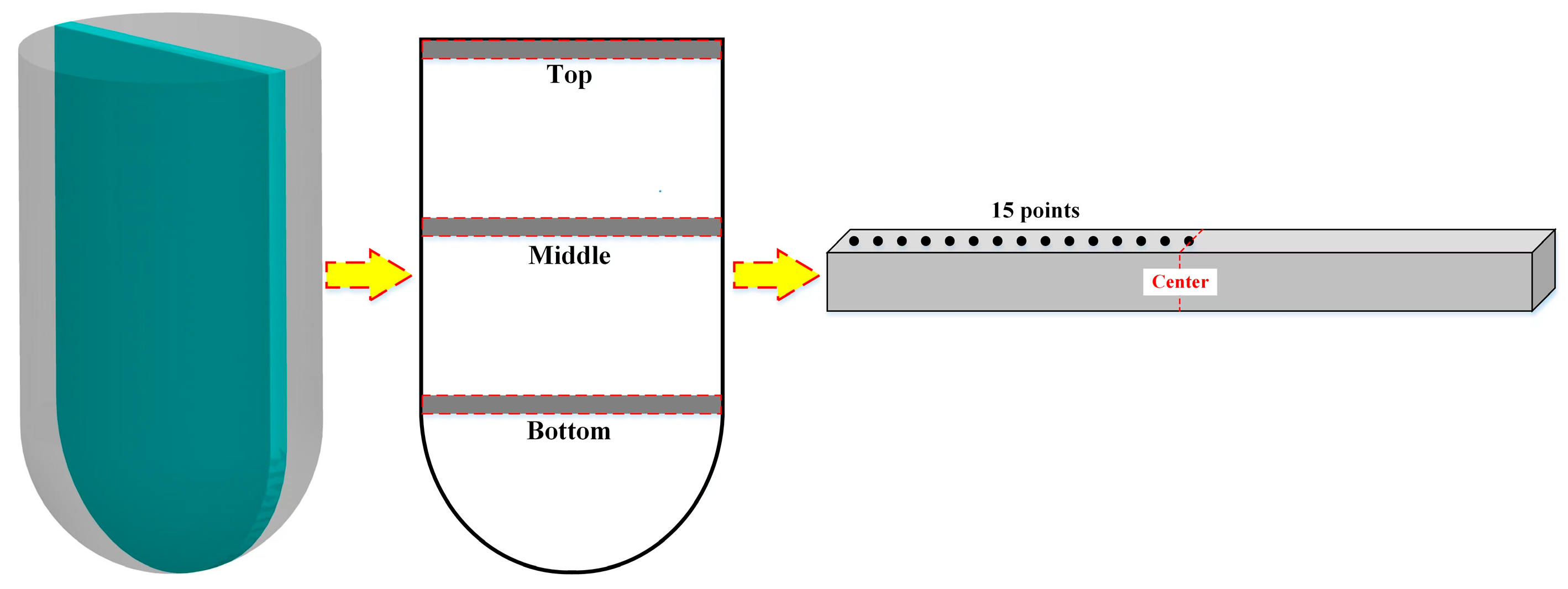
The composition segregation test was conducted using a GDS-850A glow discharge atomic emission spectrometer (LECO Corporation, St. Joseph, MI, USA), with argon as the excitation gas and a test pressure of 850 Pa. The segregation test at different positions is indeed for determining the solute homogeneity of ingot during the solidification process. The sampling diagram is shown in Figure 3. Three positions, namely the top, middle, and bottom at ingot, were sampled from each steel ingot. For the sample at each position, 15 sampling points were taken from the edge to the center, as shown in Figure 3, and the sampling positions of the two steel ingots were ensured to be the same.

2.5. Mechanical Property Testing

Tensile testing was performed at room temperature (25 °C) using a CMT5105 electronic universal testing machine (Shenzhen Xinsansi Materials Testing Co., Ltd., Shenzhen, China) with a crosshead speed of 1 mm/min. Three replicate tests were conducted for each sample group, with the results averaged for statistical reliability. Fracture surface morphology was subsequently examined by scanning electron microscopy. Microhardness measurements were obtained using a Q10M Vickers microhardness tester (Qness GmbH, Golling an der Salzach, Austria) under a 0.2 kgf load with a 15 s dwell time. To ensure measurement accuracy and account for potential heterogeneity, twelve indentation points were systematically selected across each specimen surface, and the results were averaged.

3. Experimental Results

3.1. Phase Analysis

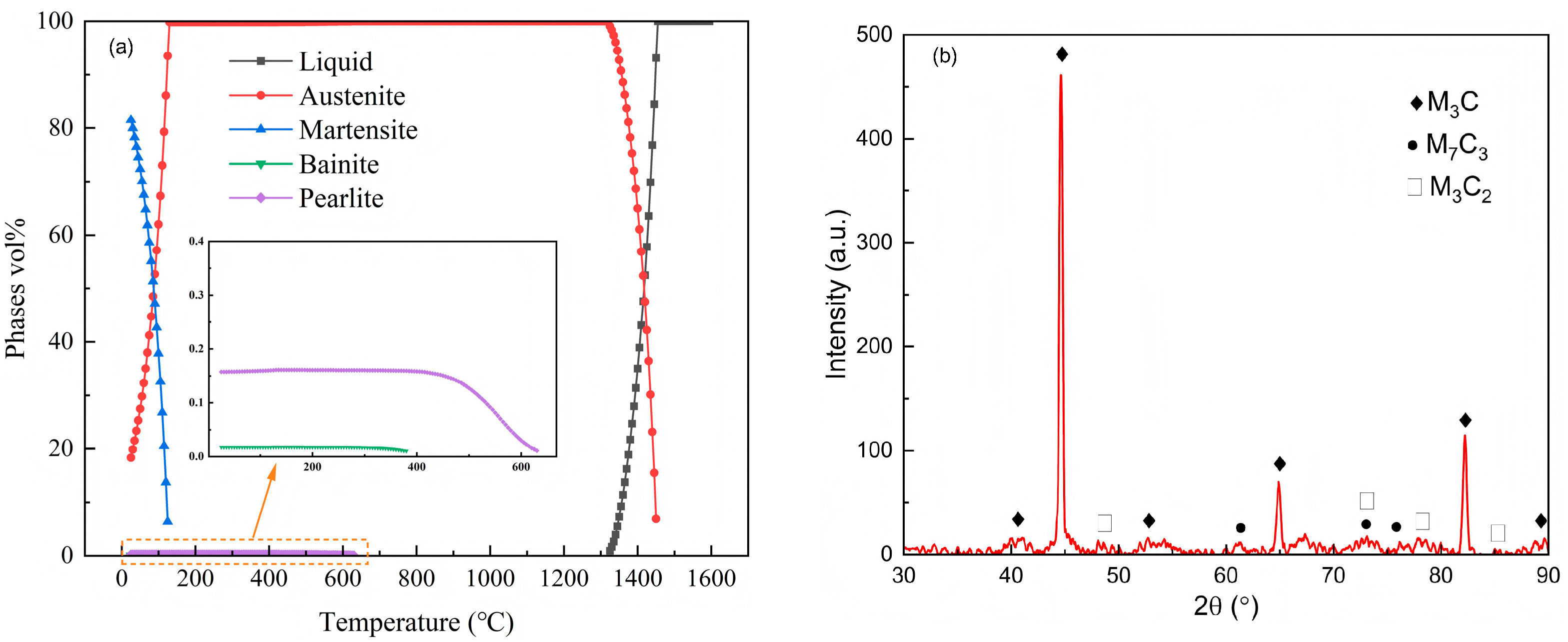
Thermodynamic software JMatPro 9.0 was used to conduct phase analysis on GCr15 steel, as shown in Figure 4a. The figure presents the mole fractions of precipitated phases and phase transformations as a function of temperature. The formation of carbides is attributed to the high carbon content in local areas during solidification, leading to their direct precipitation from the liquid phase. Three main carbides are precipitated, namely cementite, M3C2, and M7C3. The XRD test was conducted for verifying the thermodynamic calculation, which was carried out at a scanning speed of 3°/min. The type of carbide is determined by referring to standard card and obtained peaks. As indicated by the XRD analysis results shown in Figure 4b, the carbides in the segregation zone are M3C, M3C2, and M7C3. M3C2 and M7C3 carbides account for only a small proportion of the total carbides.
Figure 5 shows the distribution of C element from the edge to the center of the castings under different casting conditions at different positions. The experimental results were obtained by taking 15 points from the edge to the center of the casting. As can be seen from the figure, under natural solidification conditions, the C element content of the casting (5a) is relatively low and shows a negative segregation state, and the content distribution is uneven. The average C element content at the top and middle positions is approximately 0.3 wt.% and 0.25 wt.%, respectively, and the maximum C element content can reach 0.51 wt.%. Moreover, the degree of C element content segregation in the center is significantly higher than that at the edge. For the castings with inserted electrodes, the average C element content at the top and middle positions is approximately 0.49 wt.% and 0.47 wt.%, respectively, and the distribution is uniform.

3.2. Microstructure Observation

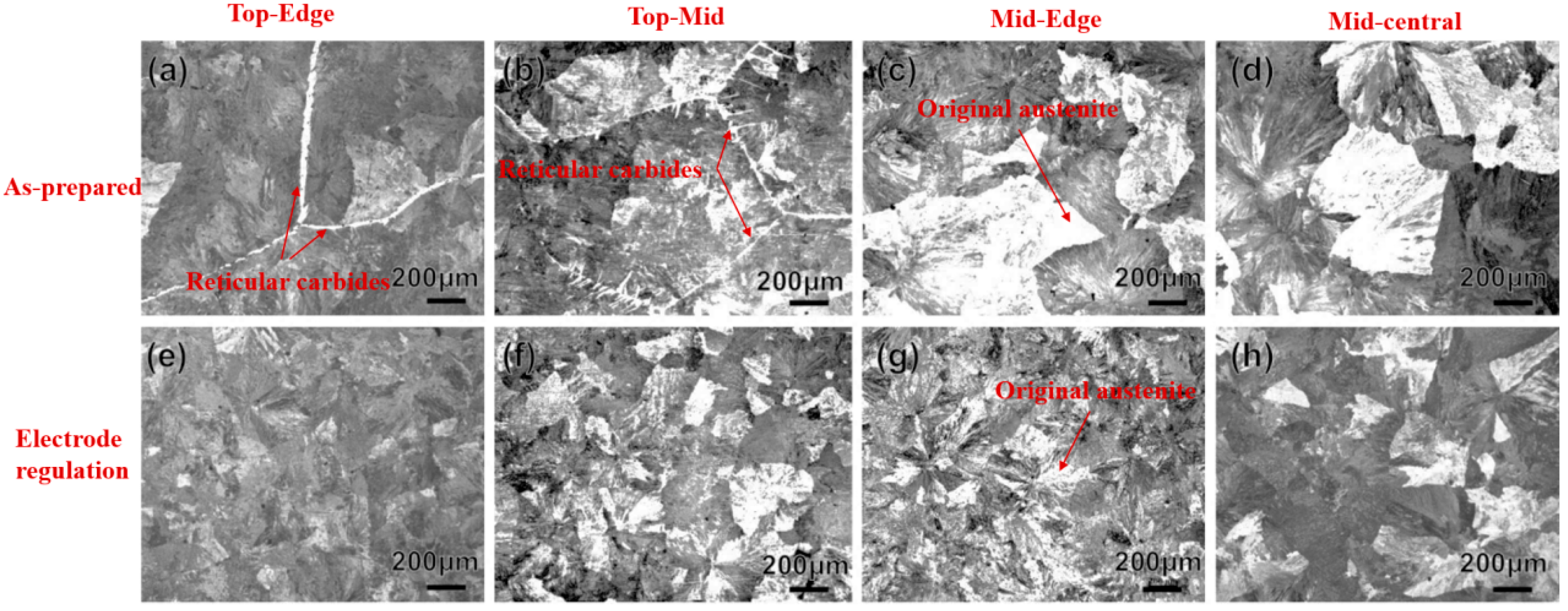
In Figure 6, reticular carbides (Figure 6a,b) were found at the upper edge and core of the ingot without an applied magnetic field. After applying an electric field, the reticular carbides disappeared (Figure 6e,f), and the original austenite grains of the ingot under the electric field were significantly refined (Figure 6c,g). The microstructure of the ingot’s edge and core became more uniform after the application of the electric field. The original austenite grains in the middle edge and core of the ingot without an electric field were coarse, but they were significantly refined after the application of the electric field. This indicates that the electric field has a significant influence on the morphology of the ingot during solidification. Under the effect of the electric field, the metal melt pool changes, with the central molten steel moving towards the periphery under the action of electromagnetic force, reducing the depth of the central molten steel and increasing the contact area between the molten steel at the edge and the mold, effectively improving the heat transfer conditions. The relative movement between the molten steel and the mold increases the convective heat transfer rate, while in the absence of an electric field, the molten steel is stationary and only conducts heat transfer. The improved heat transfer conditions by the electric field are conducive to reducing the undercooling degree of the transformation from the original austenite to pearlite, allowing the molten steel to solidify and enter the solid–liquid two-phase region as soon as possible, increasing the crystallization rate, reducing the local solidification time of elements, and thus refining the microstructure of the ingot.

3.3. Mechanical Properties and Hardness

Figure 7 presents the mechanical property data at different positions under two experimental conditions. Figure 7a shows the stress–strain relationships under different experimental conditions. Generally, the yield strength and fracture strain of the as-cast ingot without electrode insertion at different positions are relatively low, indicating poor plasticity and lower tensile strength of the material. In contrast, the ingot with electrode insertion exhibits higher yield strength and fracture strain, especially in the middle region (green), demonstrating superior mechanical properties. This is related to the role of electrode insertion in promoting a more uniform composition distribution and optimizing the grain structure. Regarding tensile strength and elongation (Figure 7b), the middle part of the electrode-inserted ingot shows the highest tensile strength of 569 MPa, while the tensile strength of the non-electrode-inserted ingot is relatively lower. The tensile strengths in the upper and middle parts were increased by 84.6% and 29.6%, respectively. The trend of elongation is opposite to that of tensile strength; positions with higher strength usually have lower elongation. This suggests that electrode insertion may promote finer grains or a more uniform microstructure but leads to a certain degree of increased brittleness. In terms of hardness (Figure 6c), the hardness values at all positions of the electrode-inserted ingot are significantly higher than those of the non-electrode-inserted ingot. The hardness distribution at the top is more dispersed than that at the middle, possibly due to the slower cooling rate at the top, leading to coarser microstructure, the hardness at the middle is more stable and overall higher, especially for the middle sample of the electrode-inserted ingot, indicating a more uniform microstructure in this region, benefiting from the improved heat conduction after electrode insertion.

3.4. Fractographic Characterization

Due to the higher mechanical properties exhibited in the middle of the ingots under both experimental conditions, this section only discusses the fracture morphology of the middle of the ingots. Figure 8a,b show the fracture morphology of the middle of the ingots under the conditions of no electrode insertion (a) and electrode insertion (b), respectively. The fracture surface in Figure 8a is relatively flat, presenting a large cleavage fracture surface with a relatively clear texture. Some areas have dimple structures, and the fracture surface has certain lamellar structure characteristics. It is speculated that the crack propagates along the grain boundaries or certain specific crystal planes. A large crack propagation area is observed, indicating that the fracture may be mainly brittle, accompanied by defects such as cracks and shrinkage cavities. The fracture surface in Figure 8b has more tear fiber-like features, showing more obvious ductile fracture characteristics. The fracture surface exhibits a more complex morphology with more signs of plastic deformation, indicating that the material has higher ductility. Compared with the case without electrode insertion, the crack propagation direction is more irregular, possibly due to grain refinement or homogenization of the microstructure. Without the effect of the electrode, the ingot may have significant dendritic segregation, with more obvious grain boundaries, which is prone to brittle fracture characteristics, leading to the dominant role of cleavage fracture. After the electrode is inserted, it may enhance the electromagnetic stirring effect, thereby refining the grains and promoting the formation of a uniform microstructure, enhancing the plasticity of the material, and causing the fracture mode to shift towards ductile fracture.

4. Numerical Results

Lorentz Force and Liquid Metal Flow

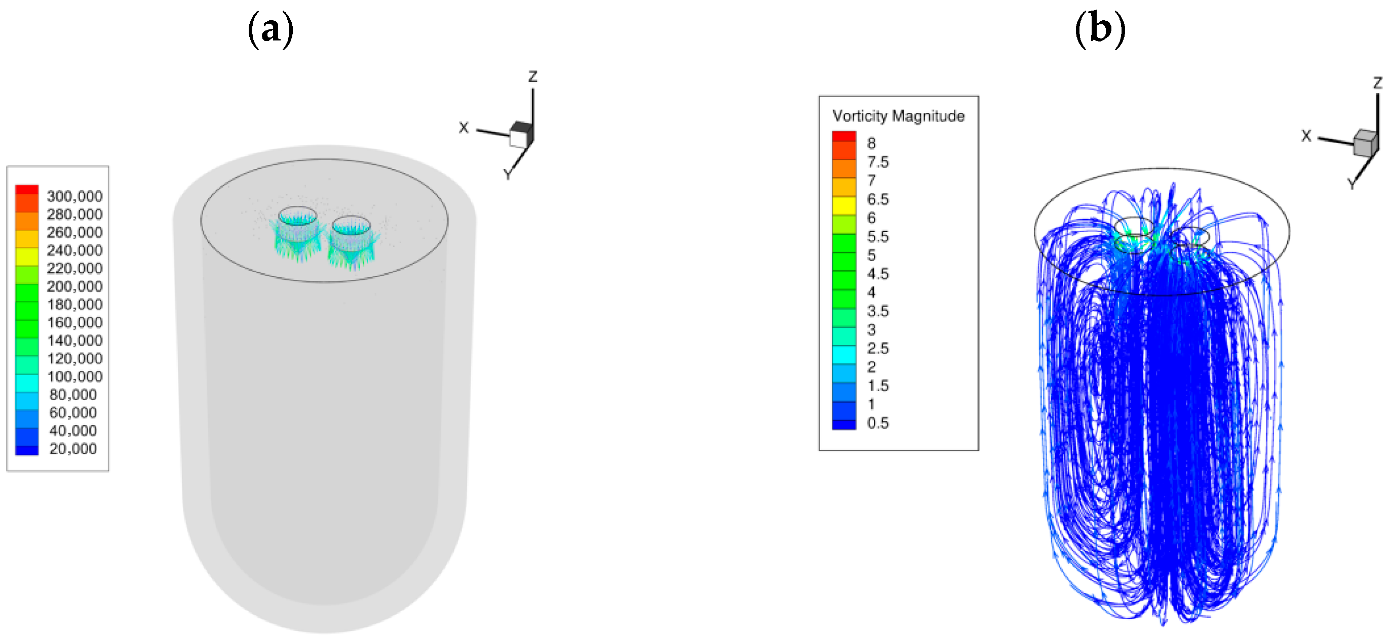
In order to better understand the flow of current induction in the mold cavity, numerical simulation was used in this section to reveal the Lorentz force inside the melt and the flow of liquid metal, and to intuitively illustrate the influence law of the inserted electrode on the steel liquid melt. Figure 9a shows that the current flowing through the electrode immediately diffuses into the melt, with the maximum current density being approximately 240,000 A/m2. It is clear that significant current concentration is obtained at the positions where the current flows from the electrode into the melt, mainly concentrated in the electrode side wall area near the free surface. The current density reaches its maximum near the electrode and flows into the interior of the melt. The distribution patterns of the induced magnetic field and the generated Lorentz force are similar. Both the magnetic field intensity and the Lorentz force intensity reach their maximum values in a narrow area and then sharply decrease in the bulk melt due to the widening of the current. Particularly, due to the interaction between the diffused current and its self-induced magnetic field, the strong Lorentz force distributed in a small domain is almost in a downward direction. This results in the generation of two strong downward-flowing jets, causing forced flow throughout the interior of the melt.
Figure 9b presents an internal streamline diagram, which shows the flow lines inside the molten steel during solidification. Obviously, after the current is introduced, disturbances occur inside it, and the flow lines change significantly. After the current is applied, a weak magnetic field is induced by the current, and the liquid alloy is affected by the electromagnetic force, resulting in disturbances. The simulation yields the disturbance state as shown in the figure. The flow line trajectories are concentrated near the electrode area in the upper part of the model, and the melt flows down from the electrode position and spreads out to the surrounding walls at 1/3 from the top. The lower part of the model has less disturbance, and there are no concentrated and obvious flow line trajectories. After the steel ingot is electrified, a downward driving force is formed below the electrode due to the electromagnetic force, and the molten steel flows downward along the bottom of the electrode. When it reaches the bottom, it starts to diverge and flows upward along the outer area, forming a reflux. The maximum forced flow area is in the central region of the steel ingot. The accelerated flow of the fluid inside the molten steel can reduce defects such as composition segregation and porosity inside the steel ingot. At the same time, after electrification, Joule heat is generated at the electrode, which plays a role in thermal compensation for the nearby area.
As solidification proceeds, a thin shell forms on the inner wall of the ingot mold where the molten steel comes into contact. At this point, the molten metal changes its internal flow pattern under the influence of electromagnetic force. The flow range of the fluid approaches the bottom of the ingot, and the melt at the edge in contact with the mold wall continuously exchanges with the core metal liquid due to internal convection, carrying the heat of the inner steel liquid to the outside. The uniform temperature reduces the temperature gradient, enhances the heat dissipation efficiency of the ingot and the cooling rate of the core, and creates a uniform temperature field and composition. The metal liquid temperature drops to the solidus line, and nucleation occurs simultaneously throughout the ingot in an explosive manner. The flowing fluid inside the ingot will erode the newly formed shell on the outside. When the flow velocity is large enough, it can break the initially formed dendritic arms and inhibit the growth of grains, changing the unidirectional growth to disordered growth. This reduces the formation of columnar crystals. The flowing steel liquid reduces the time difference between the solidification of the inside and outside of the ingot, which is more conducive to the feeding of the molten steel to the inside of the ingot, reducing defects such as shrinkage porosity and shrinkage cavities inside the ingot, improving the situation of element segregation, increasing the nucleation rate, preventing excessive growth of silicon, and obtaining a fine solidification structure.

5. Discussion

5.1. Influence of Electrodes on Microstructure

Based on the above results, it has been confirmed that the induced eddy current is the main cause of the grain refinement observed in the DC-treated samples. Under natural solidification conditions, liquid metal nucleates and grows to form coarse dendrites, as shown in Figure 10. After the insertion of electrodes, the electromagnetic force causes forced flow in the melt, which leads to local fluctuations in temperature and concentration distribution within the mushy zone, causing the local melting of dendrite side arms. The melted dendrites can serve as new nucleation sites and continue to grow (Figure 10), achieving the purpose of grain refinement. This is consistent with the research results of Bao et al. [16] Additionally, the insertion of electrodes can enhance the intensity of forced flow, which helps the melted dendrites to be carried by the melt flow and nucleate and grow in the undercooled regions. High undercooling and low thermal gradients are conducive to grain refinement because the survival probability of dendrite fragments increases with the increase in the undercooled region and forces these nuclei into the melt interior. Similar situations were also observed in Figure 6b,d, where the austenite grain size in the central region of the ingot was significantly reduced, and the grain boundaries were clearly defined.
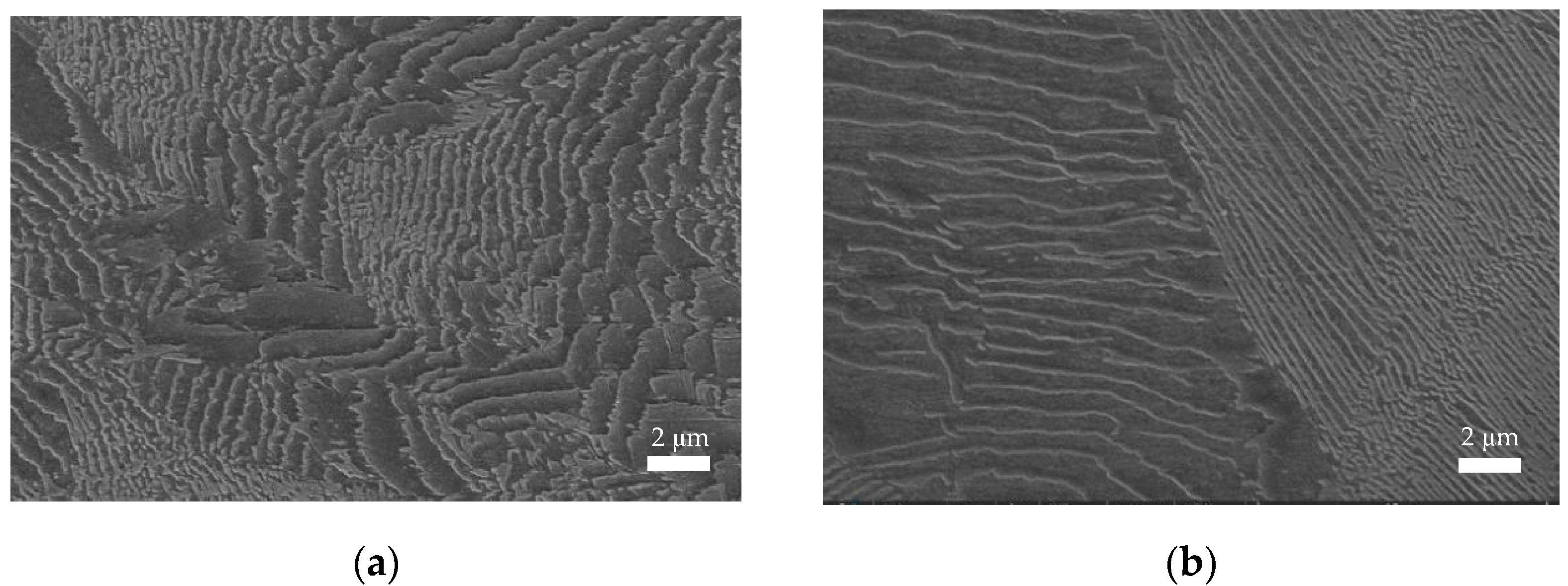
Forced eddy currents help to form a central undercooled zone to lower the temperature. The forced melt convection generated by the electrode plays a crucial role in reducing the segregation of C elements. The experimental results (Figure 5) confirm this view, and the schematic diagram is shown in Figure 10. Without the insertion of the electrode, the distribution of C atoms is disordered and uneven. With the addition of the electrode, forced flow is generated at the center of the eddy current, and the C atoms transform to a uniform distribution under the action of electromagnetic force, reducing the segregation. This leads to an improvement in both the internal quality and hardness of the ingot (Figure 7c). Figure 11 shows the pearlite microstructure of the ingot core under two experimental conditions. It can be seen from the figure that the pearlite spacing after the insertion of the electrode is significantly smaller than that of the sample without the electrode. The research found that during the transformation from austenite to pearlite, the greater the undercooling, the finer the pearlite lamellae formed. This is because when the temperature for the transformation from austenite to pearlite decreases, the introduction of the electrode increases the undercooling in the core of the ingot, which slows down the diffusion speed of carbon atoms. This makes it difficult for carbon atoms to migrate over large distances, resulting in the formation of pearlite with smaller lamellar spacing. Such fine lamellar pearlite usually has higher strength and hardness, and its plasticity and toughness are also improved, which is consistent with the research results in Section 3.3.
Figure 11 presents the SEM images of steel ingots under different experimental conditions. From the SEM image in Figure 11a, the lamellar structure of pearlite can be observed. Without the application of an electric field, the lamellar spacing of pearlite shows certain characteristics. At this time, the degree of undercooling is mainly determined by conventional factors such as cooling rate, and the lamellar spacing of pearlite reflects the transformation result under such conventional undercooling conditions. In contrast to Figure 11b, after the application of an electric field, the lamellar spacing of pearlite significantly decreases and becomes uniform. It can be clearly seen that there is a difference in the lamellar spacing of pearlite between the application and non-application of an electric field. The lamellar spacing (λ) of pearlite and the degree of undercooling (ΔT) usually satisfy the Zener formula:
When the degree of undercooling increases, the driving force for phase transformation rises, resulting in a finer pearlite structure. The polarization effect of the electric field promotes atomic diffusion and reduces the critical nucleation work, leading to phase transformation at a higher temperature (ΔT decreases). The interlamellar spacing of pearlite decreases, increasing its resistance to plastic deformation and significantly enhancing its strength and hardness.

5.2. Influence of Electric Field on Internal Flow of Steel Ingots

Based on the experimental results and corresponding numerical simulations, it can be concluded that fluid flow plays a crucial role in the internal quality of steel ingots. This is consistent with previous studies on the correlation between fluid flow and the formation of internal quality in steel ingots. Electromigration is defined as the movement of atoms caused by an applied electric field, which can lead to the relative movement of solute and solvent atoms in metal alloys [20]. This means that if the applied current is reversed, the distribution of solute atoms will change. In addition, free energy minimization [18,19] and the Lorentz force [21,22] can also cause the separation of particles with lower electrical conductivity in the melt. The purpose of this paper is to measure the flow rate during the solidification process of GCr15 steel liquid and explore the influence of current distribution intensity on forced flow. The figure shows the vertical velocity at three positions with electrodes inserted into the steel liquid. The same flow pattern can be observed at different positions in the steel ingot, that is, the flow direction at the axis of the cylinder is downward at the top and upward at the bottom. Downstream flow is generated below the electrode, as shown in the figure. The velocity measurement from the side wall of the plane perpendicular to the plane containing the two parallel electrodes shows upward flow. The current of the electrode flows through the surface of the electrode, and the flow intensity in the melt is significantly enhanced at all positions. Particularly, at the position below the inserted electrode, the maximum vertical velocity was only mm/s without the electrode, but it reached mm/s after the electrode was inserted. The results indicate that inserting electrodes can achieve higher flow intensity, providing the possibility of obtaining a more uniform grain structure. Therefore, the best explanation for the internal quality driving effect in this paper is forced flow.

6. Conclusions

This study integrated numerical simulations and experiments to establish clear process–microstructure–property–performance relationships for GCr15 bearing steel under double-electrode regulation. The key findings and practical implications derived from this study are as follows:
Double-electrode regulation modulates solidification behavior through forced convection, which breaks solute enrichment layers and accelerates solute diffusion—directly refining grains, suppressing columnar crystal growth, and promoting equiaxed crystal formation. This microstructural optimization, in turn, enhances mechanical performance—tensile strengths in the upper and middle regions increased by 84.6% (from 241 to 439 MPa) and 29.6% (from 445 to 569 MPa), respectively, while compositional segregation (notably homogenizing carbon distribution) was reduced.
These improvements translate to tangible performance gains for bearing applications: refined microstructures and reduced segregation enhance fatigue resistance and wear performance, critical for extended service life under cyclic loading. For bearing design, the optimized process supports higher load-bearing capacities, with the improved tensile strength enabling operation in harsher environments (e.g., elevated temperatures or heavy-duty conditions). Based on the observed effects, the recommended processing window for double-electrode parameters (consistent with the refinement and segregation mitigation reported) balances microstructure uniformity and mechanical performance, providing actionable guidance for industrial production of high-performance GCr15 bearings.

Author Contributions

Conceptualization, J.Z., X.A. and X.M.; Methodology, Y.Z. and M.W.; Software, Q.X.; Validation, S.L. (Shengli Li); Investigation, Q.X. and S.L. (Siyao Liu); Resources, S.L. (Shengli Li), X.A., Y.Z. and M.W.; Data Curation, Q.X. and J.Z.; Writing—Original Draft, S.L. (Siyao Liu); Writing—Review and Editing, Y.Z., X.M. and M.W.; Supervision, S.L. (Shengli Li), X.A., Y.Z., X.M. and M.W. All authors have read and agreed to the published version of the manuscript.

Funding

The present work was financially supported by Major Project of Liaoning Province Innovation Consortium (2023JH1/11200012), the Fundamental Research Funds for the Liaoning Universities (LJ212410146076, LJ212410146038, LJ222410146022, LJ232410146036, JYTQN2023242), Natural Science Foundation of Liaoning Province (2024-BS-221), and Outstanding Young Scientific and Technological Talents Project of University of Science and Technology Liaoning (2023YQ07).Liaoning Provincial Department of Education Basic Scientific Research Project for Universities and Colleges in 2025 (Grant No. LJ242510146005).

Data Availability Statement

The data presented in this study are available on request from the corresponding author.

Conflicts of Interest

The authors declare no conflict of interest.

References

  1. Beswick, J.M. The effect of chromium in high carbon bearing steels. Metall. Trans. A 1987, 18, 1897–1906. [Google Scholar]
  2. Shi, C.-B.; Huang, Y.; Zhang, J.-X.; Li, J.; Zheng, X. Review on desulfurization in electroslag remelting. Int. J. Miner. Metall. Mater. 2021, 26, 18–29. [Google Scholar]
  3. Schlautmann, M.; Koster, M.; Krieger, W.; Groll, M.; Schuster, R.; Bellmann, J.; Frittella, P. Measurement and Model-Based Control of Solidification in Continuous Casting of Steel Billets. Appl. Sci. 2023, 13, 885. [Google Scholar] [CrossRef]
  4. Shi, C.-B.; Wang, S.-J.; Li, J.; Cho, J.-W. Non-metallic inclusions in electroslag remelting: A review. J. Iron Steel Res. Int. 2021, 28, 1483–1503. [Google Scholar] [CrossRef]
  5. Shen, W.-L.; Zhang, Z.-C.; Luo, X.-Y. A Study on Behavior of Oxide Inclusions in Bearing Steel GCr15 at Refining End of a 60 t LF. Spec. Steel 2018, 39, 18–23. [Google Scholar]
  6. Cho, J.; Joshi, M.-S.; Sun, C.-T. Effect of inclusion size on mechanical properties of polymeric composites with micro and nano particles. Compos. Sci. Technol. 2006, 66, 1941–1952. [Google Scholar] [CrossRef]
  7. Agarwal, N.; Kahn, H.; Avishai, A.; Michal, G.; Ernst, F.; Heuer, A.-H. Enhanced fatigue resistance in 316l austenitic stainless steel due to low-temperature paraequilibrium carburization. Acta Mater. 2007, 55, 5572–5580. [Google Scholar] [CrossRef]
  8. Zhou, D.-G.; Fu, J.; Wang, P.; Xu, J.-H.; Xie, Y.-Q.; Li, Z. Formation Mechanism of Carbon Segregation for Bearing Steel Concasting Billet and Its Influencing Factors. J. Univ. Sci. Technol. B 1999, 21, 131–138. [Google Scholar]
  9. Xiao, C.; Zhang, J.-M.; Luo, Y.-Z.; Wei, X.-D.; Wu, L.; Wang, S.-X. Control of Macrosegregation Behavior by Applying Final Electromagnetic Stirring for Continuously Cast High Carbon Steel Billet. J. Iron Steel Res. Int. 2013, 20, 13–20. [Google Scholar] [CrossRef]
  10. Yang, Z.-G.; Wang, B.; Zhang, X.-F.; Wang, Y.-T.; Dong, H.-B.; Liu, Q.J. Effect of Electromagnetic Stirring on Molten Steel Flow and Solidification in Bloom Mold. Iron Steel Res. Int. 2014, 21, 1095–1113. [Google Scholar]
  11. Zhou, S.-C.; Bai, C.-G.; Lei, Y.; Ren, Z.-D.; Cao, P.-J.; Yang, Z.-L. Effect of low-frequency rotary electromagnetic-field on solidification structure of continuous casting austenitic stainless steel. J. Cent. South Univ. Technol. 2009, 16, 360–364. [Google Scholar] [CrossRef]
  12. Tomar, N.; Pradyumna, S.; Jain, J. Analysis of microscopic images using image processing to measure homogeneity of metal powder mixture samples. Powder Technol. 2024, 444, 119980. [Google Scholar] [CrossRef]
  13. Cha, P.R.; Hwang, Y.S.; Nam, H.S.; Chung, S.-H.; Yoon, J.-K. 3D numerical analysis on electromagnetic and fluid dynamic pheonomena in a soft contact electromagnetic slab caster. ISIJ Int. 1998, 38, 403–410. [Google Scholar] [CrossRef]
  14. Tang, G.-P.; Luo, B.-Y.; Sun, Z.; Feng, M.-L.; Lin, W.-H.; Xia, Z.-B.; Lin, Z.-Z.; Zheng, T.-X.; Zhou, B.-F.; Shi, P.-J.; et al. Evolution of Solid-Liquid Interface Influenced by Fluid Flow During Transverse Static Magnetic Field-Electric Current-Assisted Directional Solidification. Metall. Mater. Trans. B 2024, 55B, 4200–4215. [Google Scholar] [CrossRef]
  15. Cai, B.; Kao, A.; Boller, E.; Magdysyuk, O.-V.; Atwood, R.-C.; Vo, N.-T.; Pericleous, K.; Lee, P.-D. Revealing the mechanisms by which magneto-hydrodynamics disrupts solidification microstructures. Acta Mater. 2020, 196, 200–209. [Google Scholar] [CrossRef]
  16. Bao, X.-Y.; Ma, Y.-L.; Xing, S.-Q.; Liu, Y.-Z.; Shi, W.-W. Effects of Pulsed Magnetic Field Melt Treatment on Grain Refinement of Al-Si-Mg-Cu-Ni Alloy Direct-Chill Casting Billet. Metals 2022, 12, 1080. [Google Scholar] [CrossRef]
  17. Li, X.; Ren, Z.-M. Thermoelectric Magnetic Effect and Its Effect on the Solidification Structure under Static Magnetic Fields. Mater. China 2014, 33, 349–354. [Google Scholar]
  18. Annalisa, P.; Marcello, G.; Giovina, L.-V. Comprehensive Numerical Simulation of Filling and Solidification of Steel Ingots. Materials 2016, 9, 769. [Google Scholar] [CrossRef]
  19. Zhang, C.-P.; Loucif, A.; Jahazi, M.; Morin, J.-B. FE Modelling and Prediction of Macrosegregation Patterns in Large Size Steel Ingots: Influence of Filling Rate. Metals 2022, 12, 29. [Google Scholar] [CrossRef]
  20. Li, X.; Ren, Z.-M.; Wang, H.; Li, W.-X.; Deng, K.; Zhuang, Y.-Q. Ring--Like Solidification Structure Of Mnbi Phase In Bi—Mn Alloy Under A High Magnetic Field. Acta Metall. Sin. 2004, 40, 40–45. [Google Scholar]
  21. Wang, F.; Sun, B.-Y.; Liu, Z.-Q.; Li, B.-K.; Huang, S.; Zhang, B.-J. Numerical Simulation on Motion Behavior of Inclusions in the Lab-Scale Electroslag Remelting Process with a Vibrating Electrode. Metals 2021, 11, 1784. [Google Scholar] [CrossRef]
  22. Wang, B.; Yang, Z.-G.; Zhang, X.-F.; Wang, Y.-T.; Nie, C.-P.; Liu, Q.; Dong, H.-B. Analysis of the effects of electromagnetic stirring on solidification structure of bearing steel. Metalurgija 2015, 54, 327–330. [Google Scholar]
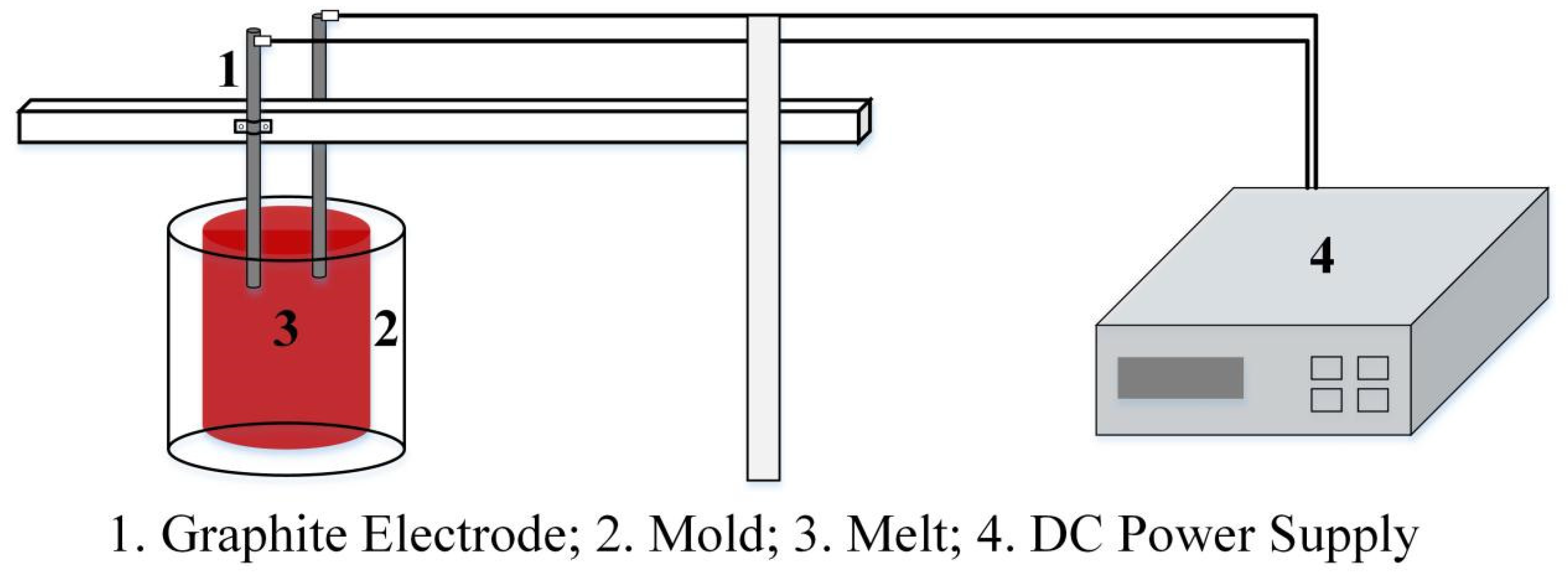
Figure 1. Schematic diagram of experimental equipment.
Metals 15 01086 g001
Figure 2. Numerical simulation grid partition (a) geometric model and (b) mesh.
Metals 15 01086 g002
Figure 3. Sampling diagram of the segregation sample.
Metals 15 01086 g003
Figure 4. Phase analysis of GCr15 steel: (a) thermodynamic calculation results and (b) XRD patterns.
Metals 15 01086 g004
Figure 5. Distribution of C from the edge to core under different casting conditions: (a) original state and (b) electrode.
Metals 15 01086 g005
Figure 6. Microstructure images (50×) under different experimental conditions (ad): as-prepared and (eh): under double-electrode regulation.
Metals 15 01086 g006
Figure 7. Mechanical properties of castings under different solidification conditions: (a,b) tensile performance; (c) hardness profile.
Metals 15 01086 g007
Figure 8. Fracture surfaces of tensile tests under two experimental conditions: (a) no electrode insertion; (b) electrode insertion.
Metals 15 01086 g008
Figure 9. Current density (a) and internal streamline diagram (b) during the steel ingot solidification process.
Metals 15 01086 g009
Figure 10. Schematic Diagram of the Principle of C Element Segregation.
Metals 15 01086 g010
Figure 11. SEM microstructure images of steel ingots under different conditions: (a) no electrode insertion; (b) electrode insertion.
Metals 15 01086 g011
Table 1. Chemical composition of GCr15 steel (wt.%).
CSiMnPSCrNiAlTiFe
1.030.240.290.180.041.440.020.010.0027Balance
Disclaimer/Publisher’s Note: The statements, opinions and data contained in all publications are solely those of the individual author(s) and contributor(s) and not of MDPI and/or the editor(s). MDPI and/or the editor(s) disclaim responsibility for any injury to people or property resulting from any ideas, methods, instructions or products referred to in the content.