Review

Review on Environmentally Assisted Static and Fatigue Cracking of Al-Mg-Si-(Cu) Alloys

1
Mechanical Systems Engineering Laboratory, Empa, Swiss Federal Laboratories for Materials Science and Technology, Überlandstrasse 129, CH-8600 Dübendorf, Switzerland
2
Joining Technologies and Corrosion Laboratory, Empa, Swiss Federal Laboratories for Materials Science and Technology, Überlandstrasse 129, CH-8600 Dübendorf, Switzerland
*
Author to whom correspondence should be addressed.
Metals 2024, 14(6), 621; https://doi.org/10.3390/met14060621
Submission received: 11 April 2024 / Revised: 13 May 2024 / Accepted: 18 May 2024 / Published: 24 May 2024
(This article belongs to the Section Corrosion and Protection)

Abstract

:
This paper reviews the relevant literature and covers the main aspects of the environmentally assisted cracking of Al-Mg-Si-(Cu) alloys. Apart from a brief overview of the major microstructural and mechanical properties, it presents research results on the corrosion sensitivity and stress corrosion susceptibility of Al-Mg-Si alloys. Possible mechanisms of stress corrosion cracking and corrosion fatigue in aluminum alloys, such as anodic dissolution and/or interaction with hydrogen, are considered. A number of factors, including atmospheric or solution conditions, applied stress, and material properties, can affect these mechanisms, leading to environmentally assisted cracking. Specific attention is given to Al-Mg-Si alloys with copper, which may increase the sensitivity to intergranular corrosion. The susceptibility to both intergranular corrosion and stress corrosion cracking of Cu-containing Al-Mg-Si alloys is mostly associated with a very thin layer (segregation) of Cu on the grain boundaries. However, the effect of Cu on the corrosion fatigue and fatigue crack growth rate of Al-Mg-Si alloys has received limited attention in the literature. At the current state of the research, it has not yet been holistically assessed, although a few studies have shown that a certain content of copper can improve the resistance of aluminum alloys to the environment with regard to corrosion fatigue. Furthermore, considerations of the synergistic actions of various factors remain essential for further studying environmentally assisted cracking phenomena in aluminum alloys.

1. Introduction

Corrosion fatigue (CF) [1] has been a topic of research since the early 20th century. The relevance of this phenomenon is mostly associated with catastrophic cases, where corrosion and static or fatigue loading are responsible for failures [2]. For this reason, the prediction of component service life under the joint actions of mechanical loading and harmful environments is a significant challenge for engineers in the aerospace, railway, automotive, and gas/oil industries, etc. Since corrosive media reduce the fatigue life of many structural materials, such as steel, magnesium, and aluminum alloys, the applicability of these metals depends on their ability to resist corrosion fatigue.
It is well known that aluminum alloys, due to their useful properties, including high strength to weight ratio, good formability, corrosion resistance, and recycling potential, are extensively used in industry. Al-Mg-Si alloys (6xxx series) have gained considerable industrial interest for building and transportation applications due to their good weldability, formability, extrudability, and low cost [3,4,5]. The 6061 alloy is commonly utilized in the aerospace industry for wings and fuselages, and for spacecraft structures and satellite surfaces [6]. The 6013-T6 alloy is the baseline material for aircraft skin and has also been considered for the fuselage of jetliners [7]. Moreover, a number of Al-Mg-Si alloys (6061, 6082, 6063, 6005, 6016, and 6111) are widely used in high-speed trains, railcars [3,5], and for auto-body sheets in the automotive industry [8].
The most important mechanical properties of Al-Mg-Si alloys and their resistance to corrosion are determined by their composition. Thus, with the addition of Cu, the strength of Al-Mg-Si alloys increases and can reach a level close to that of the 2xxx series. However, the presence of Cu and its distribution on grain boundaries can be responsible for intergranular corrosion in Al-Mg-Si alloys, as has been shown in previous studies [7,9]. Considering this, it could be hypothesized that Cu-containing 6xxx series aluminum alloys might also suffer from environmentally assisted cracking (EAC) under applied loading. Braun et al. [10,11] studied the sensitivity to stress corrosion cracking (SCC) of Al-Mg-Si alloys and suggested that it can depend on segregated (dissolved or coarsened) copper in the aged alloy microstructure. However, only limited information is available in the literature addressing the effect of composition, in particular, Cu addition, on the corrosion fatigue behavior of Al-Mg-Si alloys. Since both stress corrosion cracking and corrosion fatigue share a number of similar mechanisms (oxide film breakdown, passivation process, anodic dissolution, hydrogen embrittlement, etc.) the main purpose of this review was to compare results on SCC and CF in Al-Mg-Si alloys with a focus on the effect of the alloying elements. This study was also motivated by the ongoing importance of understanding the synergistic effect of a corrosive environment and the applied load on the degradation mechanisms of aluminum alloys.

2. Key Characteristics of Heat-Treatable Al-Mg-Si-(Cu) Alloys

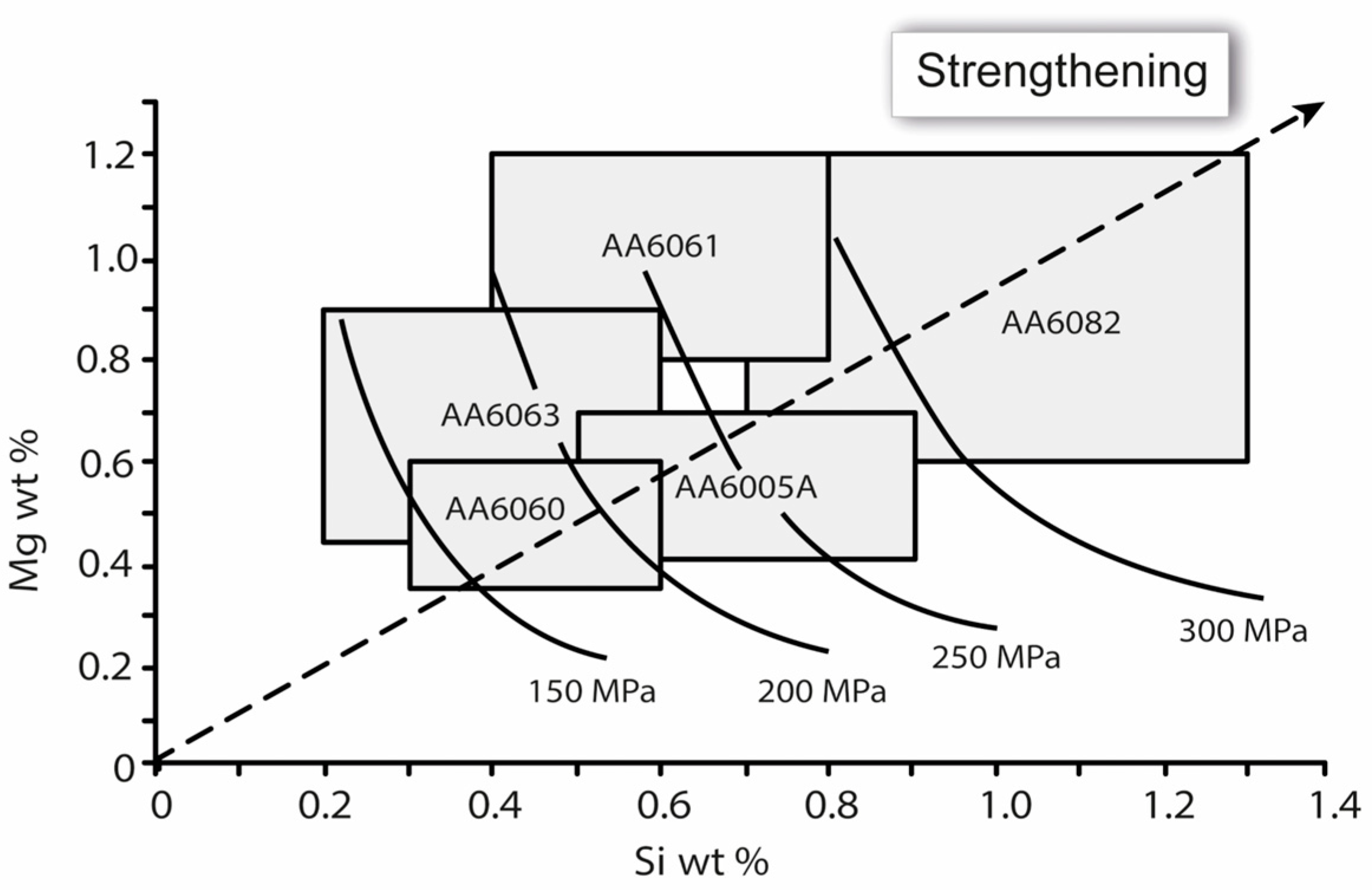
2.1. Effect of Composition and Heat Treatment on Mechanical Properties of Al-Mg-Si Alloys

The aluminum alloys of the 2xxx, 6xxx, and 7xxx series are well known to be heat-treatable [12]. Commonly used alloying elements in these alloys, such as Mg, Si, Cu, Mn, and Zn, provide significant solid solution strength and precipitations during the aging process, thus improving the strength and hardness of the aluminum matrix. The abovementioned series also demonstrate good weldability, extrudability, formability, and corrosion resistance (Table 1) [13,14,15].
In order to provide solid solution strengthening, the alloying elements usually have appreciable solubility in the matrix. According to literature, Zn is the most soluble element in aluminum (up to 66.4 at%) [16]. For Mg and Li, the solubility in aluminum is more than 10 at% and ranges from 1 to 10 at% for Cu and Si. When the concentration of alloying elements exceeds the solubility limit, other secondary phases appear in aluminum. However, the constituent elements and secondary phases are not equally effective in terms of increasing the alloy strength [17]. In the high-purity binary aluminum alloys, Mg is more effective compared to Mn, Cu, Si, and Zn. Furthermore, strength does not always increase with the content of the alloying element. In the case of Cu, the strength increases only up to a certain concentration (~1 wt%). If the content of Cu is further increased, strength tends to decrease (Figure 1).
Depending on the total amount of Mg and Si, 6xxx series aluminum alloys may be divided into three main groups [16]. In the first group, the total amount of Mg and Si does not exceed 1.5 wt%. A typical example of this group is 6063 alloy containing 1.1 wt% of Mg2Si phase. The second group has more than a 1.5 wt% total content of Mg and Si, and about 0.3 wt% of Cu. A widely used alloy of this group is 6061 alloy. Alloys with a high concentration of Si (>0.7 wt%) comprise the third group. A common example of a high Si alloy is 6082, which is widely used in civil engineering. The effect of the Mg and Si content on the yield strength of some 6xxx series alloys is shown in Figure 2 [18].
It can be seen that alloys 6063 and 6060 have a lower amount of Mg and Si and, accordingly, a lower yield strength than 6082 alloy. The strength of 6082 alloy can vary from 320 to 340 MPa at the T6 temper. However, the lower Mg concentration (<0.6 wt%) in 6060 alloy provides its better workability and extrudability. Aluminum alloy 6061 with a Cu content of 0.25 wt% is a medium-strength alloy, with a maximum strength of 310 MPa in the T6 temper. Moreover, alloy 6013-T6, with a Cu content of more than 0.64 wt%, has a strength of 406 MPa [19]. Mrówka-Nowotnik et al. [20] investigated the effect of the chemical composition of 6061, 6063, and 6082 alloys on their mechanical properties. The effect of aging time was also considered. The highest hardness, yield, and tensile strength at the T6 temper were observed for the 6061 aluminum alloy with the highest concentration of Si and Mg, Cu, Mn, and Fe. The study by Kairy et al. [21] showed that, among the observed Cu-free aluminum alloys, those with a Si:Mg ratio of ~1 have the highest hardness for identical aging conditions. With the addition of Cu, the hardness increased. In general, optimal mechanical properties of age-hardenable alloys can be achieved by aging after solution treatment and quenching (mostly the T6 temper) [22,23]. Moreover, during heat treatment, these alloys can undergo a complex decomposition and microstructural change [24,25,26].

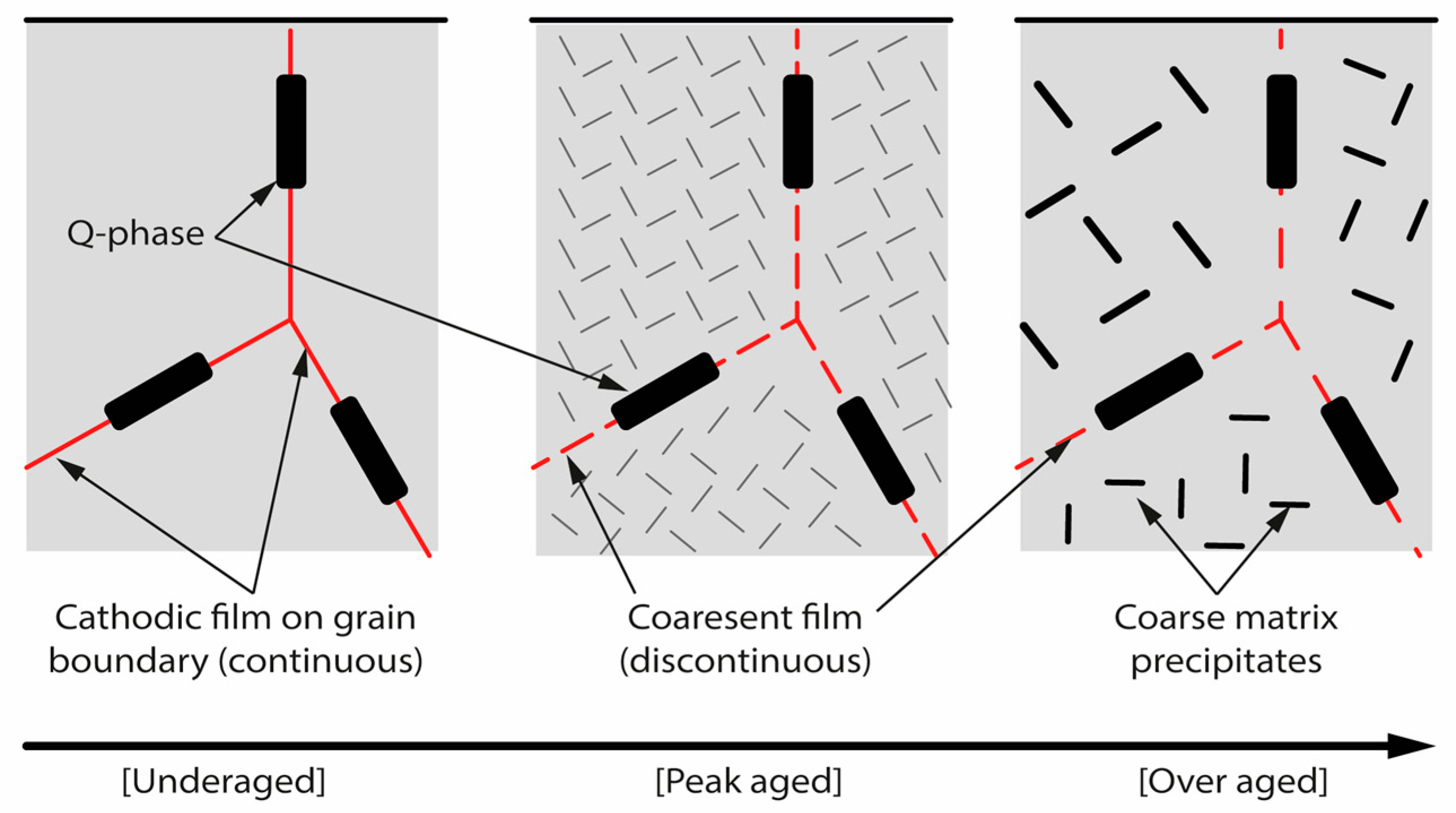
2.2. Microstructure and Precipitates Sequence of Al-Mg-Si-(Cu) Alloys

Typically, precipitates in aluminum alloys segregate on grain boundaries. Their composition, size, and morphology can alter a wide range of mechanical properties of the material and its susceptibility to intergranular corrosion [27,28,29]. The aging sequence of Al-Mg-Si alloy and the morphology of precipitates have been widely studied in the literature [22,30,31,32]. However, open questions concerning the precipitation process, composition, size, and distribution of intermediate metastable phases still exist.
Generally, accepted precipitation sequences during the aging of Al-Mg-Si alloys can be shown as follows:
Supersaturated solid solution → Mg, Si atomic clusters→ Guinier-Preston (GP) zones (Pre-β″) → β″ → β′, U1, U2, B′ → β, Si.
According to Edwards et al. [22], clusters and co-clusters of Si and Mg atoms appear at the early stages of the aging. The next phases, which form from Si/Mg atoms, are GP zones [33]. Fang et al. [32] showed that coherent GP zones have spherical shapes about 5 nm in diameter. Under the subsequent artificial aging, GP zones can serve as nucleation sites for the needle-like β′′ phases, which are the main strengthening precipitates in 6xxx series alloys with peak hardness (T6) [22,34]. The stoichiometry of the β′′ phase was proposed by Andersen et al. as Mg5Si6 [30]. An overview of the main phases appearing during the precipitation hardening of Al-Mg-Si-(Cu) alloys is present in Table 2.
The Mg5Si6 phase is followed by the formation of rod-like β′ precipitates. Their length and mean diameter are about 30–100 nm and 10–20 nm, respectively. The β′ phase is mostly associated with a decrease in material hardness upon the overaging process. At the final aging stage, the equilibrium plate-like β-phase with a defined composition (Mg2Si) generates and can exceed several micrometers. Segregation of Mg2Si precipitates at grain boundaries also contributes to the localized corrosion of Al-Mg-Si alloys [23,39].
The addition of Cu to Al-Mg-Si alloys introduces the Q and Q′ phases under the precipitation sequence [40,41,42]. The equilibrium Q phase can grow as macroscopic crystals outside the aluminum matrix. The exact composition of the Q phases is unclear, but it has been described as a compound of Al, Cu, Mg, and Si [21,38]. Q′ phases form as coherent needles inside the aluminum and are often assumed to have the same crystal structure and lattice parameters as Q phases.
A number of studies by Svenningsen et al. [43,44,45] demonstrated the role of heat treatment in the formation of a Cu-rich film along grain boundaries in modeled extruded 6xxx alloys (Figure 3). The alloy in the naturally aged (under-aged) state had a continuous Cu film and coarse Q-phase particles at the grain boundaries. In addition, overaging caused the rupture of the film and coarsening of the Q-phase, and a change in the corrosion behavior of the alloy. Thus, the generation of secondary phases in aluminum may be responsible for the microgalvanic driving force causing the corrosion.

3. Main Aspects Relating to Corrosion of Al-Mg-Si-(Cu) Alloys

3.1. Passivation of Aluminum

As a reactive metal, aluminum when exposed to air rapidly covers with a 1 nm thick oxide film in a few milliseconds [46,47]. In ambient conditions, the thickness of the oxide film is slightly larger. It consists of a compact Al2O3 barrier and an outer hydrated oxide layer. The same barrier (Al2O3) layer forms in dry, moist, and oxygen environments. It was reported by Jeurgens et al. [48] that an amorphous Al2O3 attains a limiting uniform thickness of less than 2 nm at low temperatures (T < 573 K). The limited growth of the oxide film under ambient conditions was well explained in the model proposed by Cabrera and Mott [49]. The authors described oxidation and ion transport due to the formation of the self-generated difference in the electric potential on the metal surface, which attenuated with increasing oxide thickness. Baran et al. [50] estimated the limiting thickness of oxide to be around 1.8 nm by diminishing the oxygen adsorption energy with film growth. Moreover, the applied measuring technique and alloy composition can be crucial in determining the film thickness. For instance, a comparison of industrial aluminum by Evertsson et al. [51] showed the different oxide film thicknesses (3.5–5 nm) in several 6xxx series alloys. In addition, the thicker film on the AA 7075 alloy was associated with a higher alloying element content. The outer hydrated oxide layer builds up under contact conditions between alloy and water. Its thickness depends on environmental conditions and exposition time. Using X-ray photoelectron spectroscopy, Zähr et al. [52] determined the oxide thickness on technical aluminum alloys after storage in normal, humid, and condensate climate environments. This result showed that oxide layer was 1.5–2 times thicker under condensation.
The passive layer protects and inhibits further oxidation of aluminum, but if the environment is aggressive enough (in the presence of Cl or other halides), the oxide film can be unstable and degrade. Localized corrosion is the most known cause of aluminum damage in the passive range [53]. It usually occurs in the form of pitting. However, less frequent forms of corrosion, such as intergranular or transgranular, can occur and act as a precursor for static and fatigue corrosion cracking.

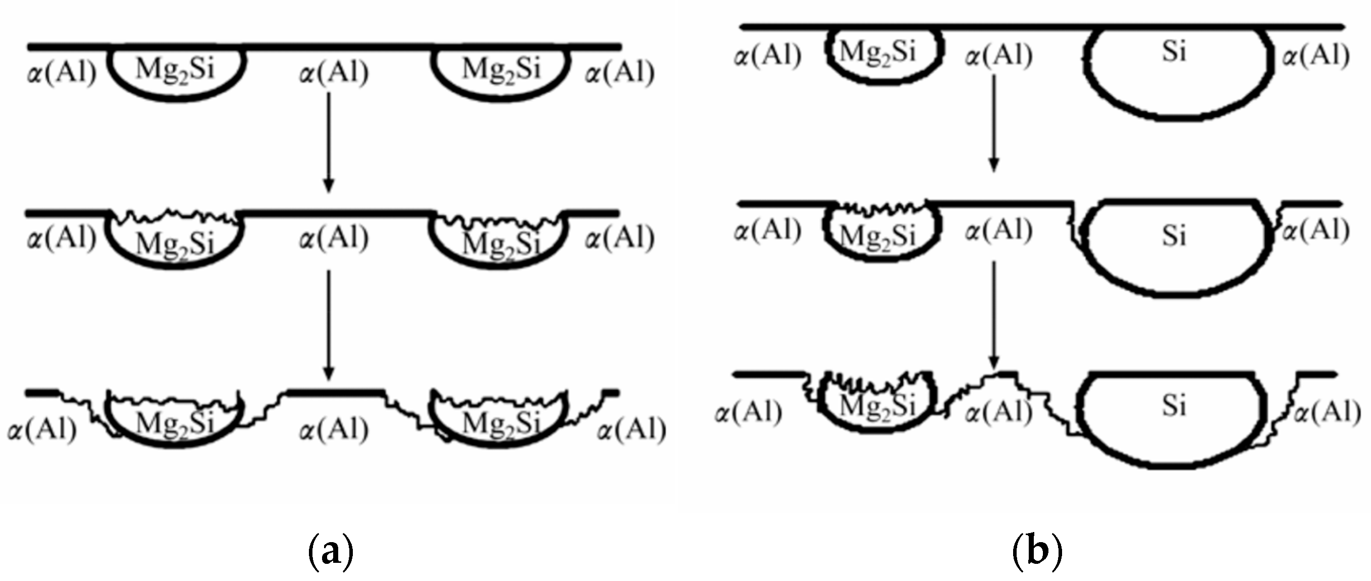
3.2. Localized Corrosion in Al-Mg-Si-(Cu) Alloys

Pitting is a dynamic event. It happens at the sensitive corrosive areas, where the protective oxide layer on a metal surface can be compromised (surface imperfections, regions with secondary phases, etc.). The summarized literature indicates the complexity of the passivity breakdown/pit initiation and propagation process, which depends on different variables. Passivity loss has been described by different mechanisms, the principal of which was highlighted by Böhni [54] as penetration, film breaking, and ion adsorption. According to McCafferty [55], the penetration of chlorides through the passive layer may occur by their transport via oxygen vacancies or water channels and local dissolution or thinning of the oxide film. Moreover, the early stage of metal pitting in chloride solution is usually connected with the formation of metastable pits [53]. This process is associated with current fluctuations when the metal is kept below the pitting potential. When conditions inside the pit promote its active state, a pit starts to grow. As acidification and the chloride concentration in the pit solution increases, it promotes a high dissolution rate and the formation of metal salt. Thus, one of the indicators for stable pit growth is the presence of the salt film covering the pit opening.
Resistance to localized corrosion can also be significantly reduced in the presence of constituent phases [53]. In the case of Al-Mg-Si alloys, secondary phases, such as coarse Fe-containing intermetallic, pure Si particles, and stable/metastable β-(Mg2Si) and Q-(Al5Cu2Mg8Si6) phases, influence corrosion susceptibility. In the case of the Mg2Si phase, it is anodic to the matrix, and the corrosion is superficial. With silicon enrichment segregated on grain boundaries, Mg2Si becomes cathodic, resulting in the selective dissolution of the matrix adjacent to the precipitate-free zone. According to Zheng et al. [56] and Zeng et al. [39], the ratio of Mg/Si and pure Si particles define the intergranular corrosion mechanism of Al-Mg-Si alloys (Figure 4a,b). With a Mg/Si molar ratio > 1.73, the preferential dissolution of Mg and the enrichment of Si transform the Mg2Si phase to cathode from anode, leading to anodic dissolution and aluminum corrosion. When the Mg/Si molar ratio is less than 1.73, corrosion initiates on the Mg2Si surface and the adjacent periphery of cathodic Si particles, which causes anodic dissolution of the aluminum matrix and, therefore, accelerates corrosion.
Svenningsen et al. [44,57] and Bartawi at al. [58,59] showed that the susceptibility to intergranular corrosion of 6xxx series aluminum alloys depends on the Cu content and the heat treatment parameters. Alloys with a low Cu content (0.0005 wt%) were essentially resistant to intergranular corrosion [57]. The greater susceptibility of the Cu-containing alloys to intergranular corrosion was attributed to the formation of a continuous Cu nanofilm along the grain boundaries that acts as the internal cathode. The formation of the discrete coarse Cu-containing particles on grain boundaries during further aging reduces the susceptibility to intergranular corrosion and microgalvanic coupling with the alloy matrix [44]. Liang et al. [60] investigated the effect of different Mg/Si ratios and Cu contents on the corrosion behavior of 6xxx series aluminum alloys. For all investigated alloys, corrosion rates were lowest in the naturally aged state. However, with the addition of Cu, alloys containing excessive Mg tended to be more corrosion resistant after artificial ageing than those containing excessive Si.

3.3. Crack Tip Environment

Understanding of EAC requires knowledge of the chemical and electrochemical conditions at the crack tip that cannot be well described by the bulk environment [61].
The typical oxygen reduction reaction in metals inside the crack along the walls rapidly depletes O2.
O2 + 2H2O + 4e ↔ 4OH.
The limitation of oxygen diffusion down the crack and concentration of metal ions near the crack tip due to anodic dissolution cause more negative corrosion potential. An analysis of the crack tip solutions in a susceptible Al-Zn-Mg-Cu alloy made by Cooper et al. [62,63] showed the high concentration of dissolved metal ions (Al3+, Mg2+, Zn2+) and Cl.
M → Mn+ + ne.
In growing EAC, hydrolysis can have a significant effect on the pH in the vicinity of the crack tip. Generated metal cations in aqueous solution reacting with water produce H+ by the following reaction:
Mn+ + H2O ↔ MOH(n−1)+ + H+.
In addition, the cathodic reactions occur near the crack tip:
H2O + e → H + OH,
H+ + e → H.
The reduction of H+ results in the formation of the more neutral pH. It is also well known that adsorbed atomic hydrogen may cause the embrittlement of some metals under special conditions.
The balance between hydrolysis and metal ion concentration affects the formation of EAC-susceptible conditions near the crack tip. Bland and Locke [61] in their review analyzed the role of mass transport during stress corrosion and fatigue corrosion cracking. It was shown that the convective mixing conditions within a crack are different for CF and SCC. In the case of SCC, advection does not occur at the crack mouth, whereas the displacement of the crack walls during cyclic loading allows fresh electrolytes to flow into the crack. In addition, the decreasing of the cyclic frequency makes refreshing the crack environment slower, and the crack tip becomes more occluded. Turnbull and Ferris [64] also predicted a critical frequency of about 1 Hz below which advection is negligible and the conditions at the crack tip become close to SCC. Moreover, a lower stress ratio (R) results in high crack closure. Since the crack acts as a pump, the mixing of the bulk and crack solution is increased due to enhanced advection. At a higher R ratio, the crack is more open under the full cycle and the same crack mouth surface contains a larger volume of solution. Under these conditions, cathodic reactions can occur for much longer and cause the polarization of crack environment, as was shown by Turnbull [64,65].

4. Mechanisms of Stress Corrosion and Fatigue Corrosion Cracking

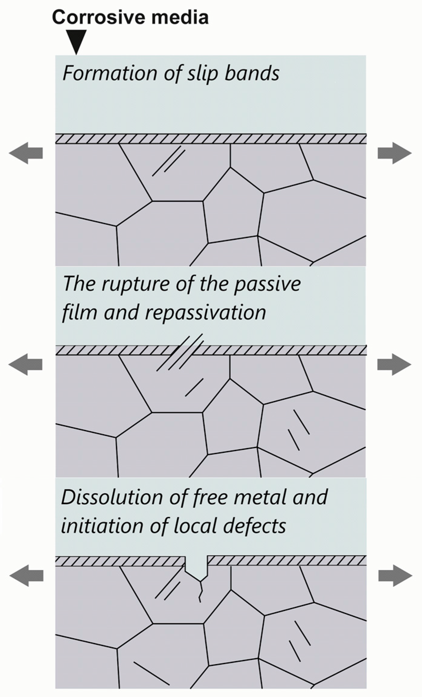
4.1. Stress-Related Corrosion Cracking

According to Jones and Ricker [66], SCC usually occurs in three main stages: crack initiation, crack propagation, and failure, which involve different mechanisms. The CF also goes through several steps: cyclic plastic deformation, crack nucleation, small crack growth, and macro crack propagation. According to El May et al. [67,68], fatigue crack initiation starts with local ruptures of the passive film by the emergence of slip bands followed by the local dissolution in de-passivated zones and the formation of localized defects (Figure 5). The authors also point out that the repassivation time under cyclic loading depends on both the kinematic of slip emergence and the time required to form the sufficient size of slip bands to initiate the passive film failure. Moreover, the damage of the surface film or local microgalvanic activity leads to localized corrosion, and the transition from pitting to cracking is the most important mode in corrosion fatigue crack growth [69].
There is still no single theory explaining SCC mechanisms for all material–environment systems. Most attempts to find a unified SCC mechanism gradually come to explaining the observation for a certain one. Furthermore, SCC can be characterized by various microfeatures of interacting systems and microprocesses. Following the analysis of such micropeculiarities, various theories of SCC have been developed [70,71,72].
In the case of aluminum alloys, the mechanisms of SCC are often attributed to three main theories: the electrochemical dissolution of anodic phases, hydrogen embrittlement, and the breakdown of the protective oxide film along the grain boundaries [73]. Corrosion fatigue is also characterized in the literature by two main categories of mechanisms: hydrogen-induced cracking and/or anodic dissolution [74,75].
The main difference between CF and SCC is the nature of the applied load (cyclic and static). SCC usually induces intergranular cracking, while CF causes a transgranular fracture, such as fatigue in air [76]. However, both intergranular and transgranular cracking can be observed in SCC as well as in CF, depending on the specific conditions. Also, the loading type may affect the localized chemical and electrochemical conditions near the crack tip [61]. The mechanisms driving EAC are still debated in the literature, but for both CF and SCC, processes such as passive film disruption, repassivation, hydrogen embrittlement, and electrochemical dissolution are used for describing materials degradation. Moreover the combination of pure SCC and fatigue mechanisms can often be considered during CF [75].

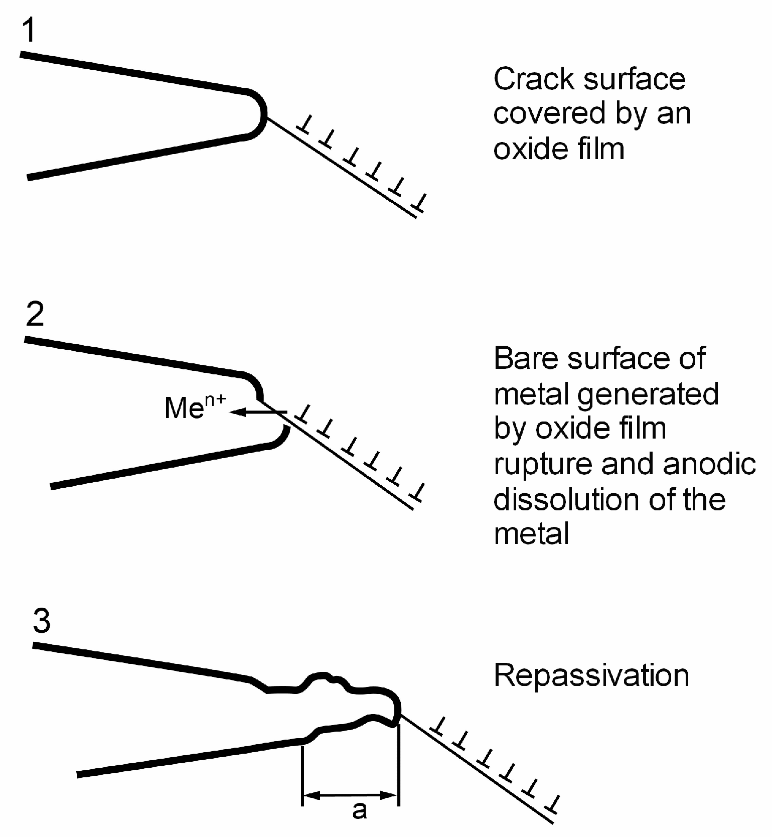
4.2. Anodic Dissolution

Anodic dissolution is a localized process that occurs at electrochemically active pathways along grain boundaries. This pathway forms due to precipitate segregation and the presence of the precipitate-free zone at grain boundaries and contributes to intergranular SCC. The dissolution of the metal near the crack can be promoted, not only by the chemically active pathway, but also by stress–strain and the local environment at the crack tip. Moreover, repassivation of the crack walls can be crucial for the local corrosion attack and crack propagation. The most well-known dissolution-based SCC process is the slip dissolution mechanism. It includes the damage of protective films by slip bands crossing the crack tip and further dissolution of the free metal surface under repassivation (Figure 6). Fong and Tromans [77] proposed a restricted slip recovery model for fatigue crack propagation. According to their model, the rate of crack growth is determined by slip reversibility, which is controlled by work hardening and recovering on a slip plane as well as oxidation kinetics and the presence of corrosion products [71,77]. Moreover, according to Magnin [75], localized dissolution can cause the formation of vacancies at the crack tip leading to cyclic softening effects.

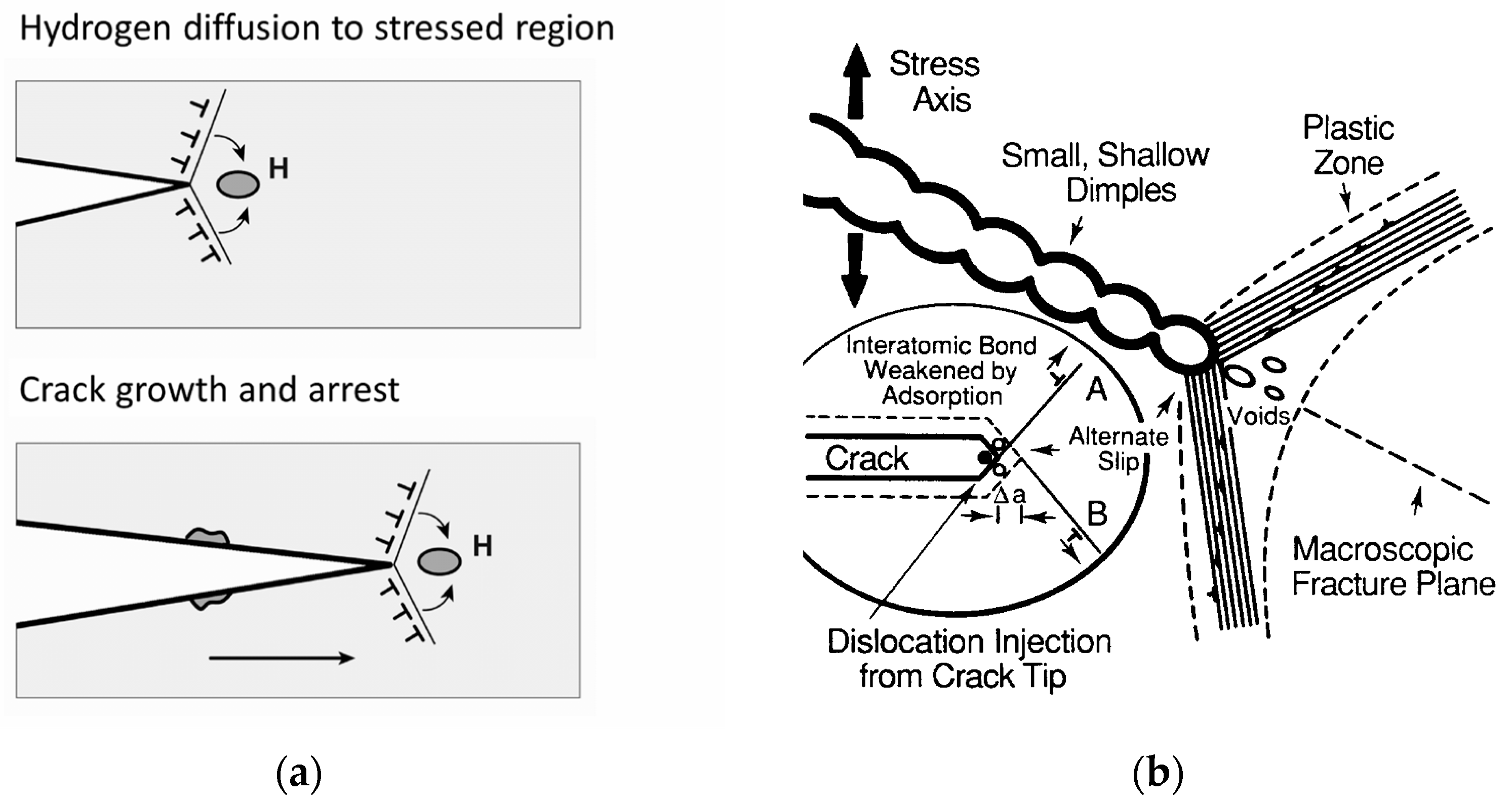
4.3. Hydrogen-Assisted Cracking

Hydrogen embrittlement is often considered as a particular type of mechanism related to SCC (and CF), since hydrogen is generated in aqueous environments [71,72,74]. Hydrogen-assisted cracking (HAC) is often invoked together with anodic dissolution in aluminum alloys. The hydrogen embrittlement mechanism can be commonly described as a decohesion model [71]. The essential characteristic of this model is that atomic dissolved hydrogen reduces the maximum cohesive strength of the metal and causes embrittlement. In the other approach, the interaction between the dislocations and the crack tip under the applied stress creates a maximum stress in front of the crack tip, to which hydrogen is driven. The accumulation of hydrogen leads to microcrack nucleation, as the local cohesive strength decreases and the movement of dislocations in the hydrogen-enriched zone is blocked. A new microcrack is generated and stops approximately before the original tip location. These processes are repeated and discontinuous crack growth can be observed (Figure 7a).
In studies by Lynch [79,80,81,82], the main emphasis was placed on the interaction between electrochemical processes and the dislocation activity at the crack tip under plastic deformation. According to Lynch, hydrogen atoms adsorbed on the surface of the crack tip and on the grain boundaries play a more dominant role in embrittlement than hydrogen atoms dissolved inside the metal. Moreover, Lynch highlighted several main mechanisms of HAC, such as hydride formation, hydrogen-enhanced localized plasticity, hydrogen-enhanced decohesion, and more complex adsorption-induced dislocation emission mechanisms (Figure 7b). In particular, an adsorption-induced dislocation emission model found a good correlation with experimental results for Al-Zn-Mg aluminum alloys [83]. According to this mechanism, the weakening of interatomic bonds due to adsorbed hydrogen atoms at the crack tips contributes to dislocation generation. The alternating slip at the crack tip promotes the coalescence of cracks with voids ahead of the crack front.
Figure 7. Schematic illustration of (a) HAC mechanism (H represents dissolved atoms of hydrogen) [71]; (b) adsorption-induced dislocation emission model (A and B indicate slip planes) (Reprinted with permission from [80]. Copyright 1989, Elsevier).
Metals 14 00621 g007

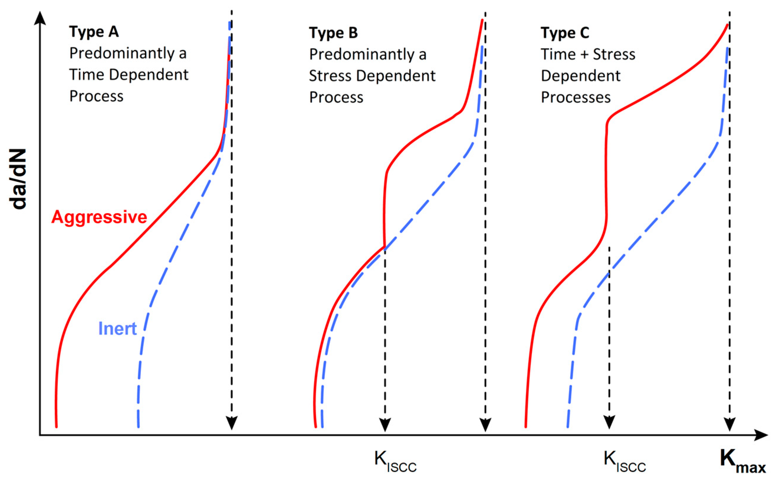
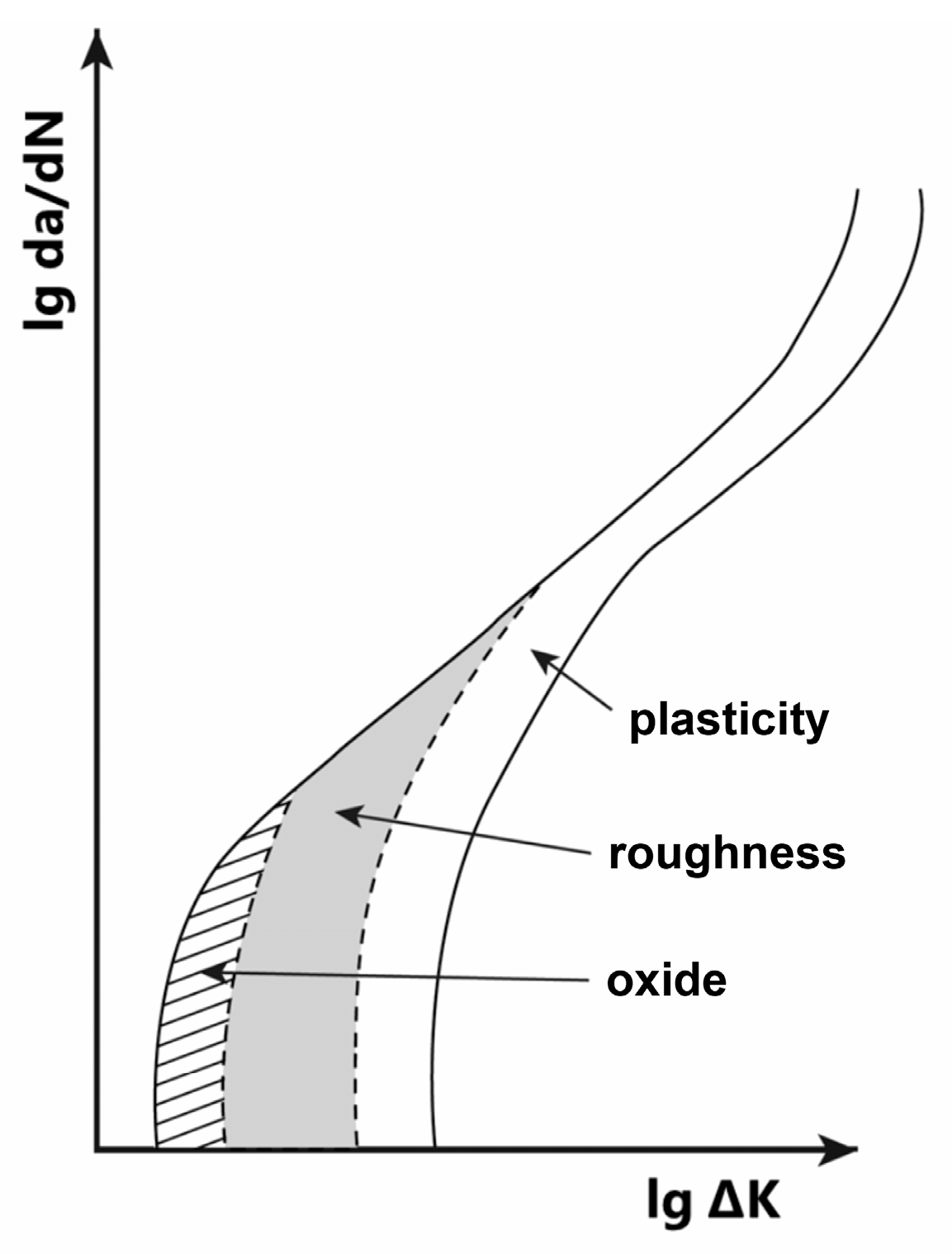
4.4. Environmentally Assisted Fatigue Crack Propagation

Comprehensive studies of CF crack propagation show that CF crack growth behavior can be divided into three main types (Figure 8) [84,85]. In the first case (Type A), the crack growth process starts at lower values of stress intensity factor, K, than in the inert (i.e., air) environment. Under such conditions, the environmental effect generally determines an increase in the crack growth rate. In the second type, crack growth behavior is aligned with the inert case until some threshold, beyond which a substantial growth occurs. Such behavior is connected with the activation of SCC growth mechanisms, while fatigue just needs to stimulate the process. The third type (Type C) of CF crack growth is a combination of the previous ones. In this case, the CF threshold is lower than for SCC and higher crack growth rates are observed, compared to the inert environment.
It should also be emphasized that corrosion fatigue crack growth behavior can be determined by the rate of passive film rebuilding after rupture by either chemical or mechanical impact. King [86] summarized that the oxidation of metals, and the applied stress rate and frequency may affect corrosion fatigue crack propagation. It was shown that the formation of a thin oxide layer could prevent crack tip rewelding and reduce slip reversibility. Moreover, when crack surfaces contact to the crack tip above the low load ratio, the oxide film breaks up, causing enhanced ‘fretting’ oxidation of the fracture surfaces. The appearance of thick and compacted layers of oxide debris causes the premature contact of the crack faces and crack closure at a part of the fatigue cycle. In addition, higher values of load ratio prevent the contact of the crack faces and the processes of the oxide build-up by fretting do not occur.
The oxide-induced crack closure effect on the threshold values was also observed in 7075 aluminum alloy and 2–25Cr-1Mo steel [86]. Vasudévan and Suresh [87] showed that the fracture surface oxidation of 2xxx and 7xxx series aluminum alloys is strongly affected by the composition and aging treatment. The obtained results indicate that both fatigue crack closure and environmental embrittlement may play a dominant role in determining the slow crack growth behavior of these alloys. For understanding fatigue crack propagation phenomena, Pippan and Hohenwarter [88] reviewed crack closure mechanisms (Figure 9). Moreover, understanding of the oxide-induced crack closure process as a function of load, the environment, and the evolution of the oxide growth process during cyclic loading requires extensive experimental and theoretical studies. Michel et al. [89] evaluated the environmental and frequency effects on fatigue crack growth in 2024-T351 and 7075-T651 aluminum alloys and reported that, in corrosive environments near the crack growth threshold, the fracture mechanism of oxide film can affect the crack growth behavior.

5. Susceptibility of Al-Mg-Si-(Cu) Alloys to Environmentally Assisted Cracking

5.1. On Stress Corrosion Cracking of 6xxx Series Aluminum Alloys

According to Burleigh [73], high strength Al alloys of the 2xxx series are susceptible to anodic dissolution-assisted SCC, but the 7xxx series are more prone to the hydrogen-induced SCC. As for 6xxx series alloys, they are more resistant to corrosion and SCC [90]. However, laboratory studies of corrosion-assisted cracking showed that Al-Mg-Si alloys can demonstrate susceptibility to SCC. For example, Brown et al. [91] noted that SCC on the transverse to the rolling direction in specimens of 6061-T4 alloy occurred only on plastically deformed (preformed) specimens and not on tensile-type specimens stressed to 75% of the yield strength. Moreover, alloy aging to the T6 temper eliminated this tendency. The influence of Cu on SCC was studied by Reboul et al. [92]. It was found that 6xxx alloys with a Cu content of about 1 wt% can be susceptible to SCC. The recrystallized products of 6013 and 6056 alloys at the T4 and T6 temper were susceptible to SCC, while proved resistance to SCC was observed in a low copper alloy 6082-T6. However, the direction of the applied stress during testing and the texture of material were not mentioned in their study.
In a series of studies by Braun [10,11,93], the susceptibility to SCC of 6061 and 6013 alloys was compared. Tempered samples (T4 and T6) were tested under static load conditions in aqueous solution of 0.6 M NaCl + 0.06 M NaHCO3. These alloys were resistant to SCC. However, under the constant tensile rate test, 6061-T4 alloy demonstrated sensitivity to SCC. The author attributed the intergranular corrosion and SCC of 6061-T4 alloy to the segregation of a very thin film of Cu at grain boundaries, which coarsened and dissolved with increasing aging, reducing the susceptibility to SCC.
The effect of the chemical composition and relative humidity (RH) on the SCC of 6xxx series alloys was studied by Ogawa et al. [94]. It was found that, in humid air, the crack growth rate increases with an excessive Si content compared to the balanced Mg2Si composition without Cu addition. In addition, the addition of Cu decreases the crack growth rate and improves the SCC performance (Figure 10). Furthermore, SEM observations demonstrated that alloys without Cu had an intergranular fracture surface, while dimple fracture surfaces were predominant for the other alloys.
Fujii et al. [95] investigated SCC nucleation in 6061-T651 alloy. Constant load testing on tensile specimens was conducted in 3.5 wt% NaCl solution. Crack initiation was independent of the type of secondary phases. SCC occurred at the pits originating from both Mg2Si and AlFeSi phases. As chemical reactions differ depending on the type of phase, the authors suggested that SCC might occur at the pits related to Mg2Si due to the hydrogen embrittlement mechanism. At the pits related to the AlFeSi phase, SCC might occur due to the anodic dissolution mechanism.

5.2. Hydrogen Effect

For a long time, hydrogen embrittlement has been considered irrelevant for aluminum. The reason for this is that aluminum does not embrittle in dry hydrogen, even at high pressure [96], and the diffusivity of hydrogen in aluminum is quite low (10–14 m2/s in the case of resistant 6061 aluminum alloy [97]). However, it was only in the second half of the last century that evidence of hydrogen embrittlement of aluminum alloys appeared. This was convincingly demonstrated by Ratke and Gruhl [98]. On the example of an aluminum–iron–manganese alloy, the authors showed that hydrogen generated by the cathodic reaction between aluminum and salt solution can move inside the matrix along grain boundaries and cause the hydrogen embrittlement of the alloy. Recent studies of the hydrogen embrittlement of aluminum alloys are also associated with hydrogen accumulation at grain boundaries and secondary phases [99,100,101,102,103].
In a study by Osaki et al. [104], the slow strain-rate test in humid air carried out for 6061-T6 aluminum alloy with a fine (7–45 µm)- and coarse (~400 µm)-grained structure was used to evaluate the susceptibility to hydrogen embrittlement. Fine-grained materials demonstrated insignificant changes in tensile properties compared with the inert environment of dry nitrogen gas, while the coarse-grained materials exhibited some change in ductility; namely, a decrease for the smooth specimen (by 7%) and an increase for the notched specimen (by 3%). Although the materials ruptured by ductile fracture independently of grain size, the characteristic feature of coarse slips and void formation promoted by hydrogen was observed.
The investigation of the effect of pH on the SCC behavior of 6082 alloy in a NaCl solution was performed by Panagopoulos et al. [105]. The brittle and intergranular SCC mechanisms on the alloy surface were observed in the acidic pH environment. In addition, galvanic corrosion with hydrogen embrittlement and mild intergranular corrosion with ductile fracture were observed in the alkaline pH and the neutral pH solution, respectively.
According to the NASA database [106], alloy 6061-T6 and 7075-T73 are categorized as negligibly susceptible to hydrogen embrittlement. Moreover, Osaki et al. [107,108,109] showed that 6061-T6 and 7075-T6 aluminum alloys demonstrate different sensitivity to hydrogen under the slow strain-rate test in humid air (Figure 11) [107]. The humid air caused significant embrittlement of 7075-T6 alloy in contrast to the high-pressure hydrogen environment [109]. In addition, 6061 alloy was found to be stable in both environments even in pure water. Such an effect can be connected with the difference in the trapping of hydrogen in alloy precipitates. Xu et al. [110] calculated the trapping energies of various intermetallic compound particles to hydrogen in high-strength aluminum alloys and showed their strong correlation with the resistance to hydrogen embrittlement in the case of Al-Zn alloy. Additionally, Safyari et al. [99] reported that the modification of 7xxx with Zr and Cr had different effects on hydrogen trapping and dispersoid–dislocation interactions that caused various HAC mechanisms of alloys. Therefore, the presence of secondary phases in aluminum alloys can affect both SCC and hydrogen embrittlement.

5.3. Corrosion Fatigue of Al-Mg-Si-(Cu) Alloys

Similar to SCC, corrosion fatigue can also be considered as an interaction of the environment–material system with many mechanical, metallurgical, and environmental variables [74,111]. All of these parameters affect the CF performance of Al-Mg-Si alloys. Chanyathunyaroj et al. [112,113] showed that the fatigue life of extruded aluminum alloy 6061 reduced by 50% during the rotational bending test with dripping salt water (Figure 12). The authors state that a 3.5% NaCl solution causes corrosion pits on the alloy surface acting as crack nucleation sites. According to a research study by Nguyen and Li [114], the fatigue strength of rolled 6061-T6 specimens in the 3.5 wt% NaCl solution under fully reversed tension–compression loading with a load frequency of 5 Hz decreased by approximately 80 MPa compared to the strength in air. A reduction in fatigue life under the rotating bending fatigue test of both bare 6061-T6 alloy and alloy with micro-arc oxidation coatings was also obtained by Madhavi et al. [115]. Kurumada et al. [116] showed the effect of the temperature and type of environment on the corrosion fatigue of 6061-T6 flat specimens. The tensile fatigue test was performed under the loading frequency of 1 Hz (R = 0.1) in tap and deionized water, and in a 50% aqueous ethylene glycol solution at two different temperatures (25 °C and 75 °C). At a temperature of 75 °C, the fatigue life was shorter than at 25 °C, and this tendency became more pronounced with the decreasing of the stress amplitude. As the temperature can influence the environment–metal surface reactions as well as many transport processes, it can be expected to affect corrosion fatigue. Moreover, corroded Mg2Si-based and Al-Fe-Si-based secondary phases were the sources of fatigue cracks, resulting in fatigue life reduction.
Weber et al. [117] showed a reduction in the fatigue strength of pre-corroded 6061-T6 aluminum. The authors found that the preliminary immersion of samples in an acidic environment (3.5% NaCl solution at pH 2) for 2 days and 24 days caused different sizes of pits. However, the fatigue life in ambient air at a loading frequency of 100 Hz of both sets was almost the same. The effect of artificial pits on fatigue behavior was also investigated by Dominguez Almaraz et al. [118]. According to this study, the formation of deeper pits and their clusters caused an increase in the concentration of stress and led to accelerated fatigue crack initiation. It was also shown that a test frequency increase from 25 to 100 Hz did not have any effect on the material fatigue life. More recent studies [119,120] also showed the detrimental effect of the environment on the fatigue life of 6082 aluminum alloy.
In a comparative review, Locke [121] summarized the oxidizing capacity and hydrogen embrittlement of widely used age-strengthened 2xxx, 6xxx, and 7xxx series aluminum alloys under CF. According this literature analysis, the rupture–repassivation interaction in the passive film of the crack tip can be governed by the repassivation time and the rate of crack tip deformation. Nevertheless, the repassivation process depends on the time between rupture events and, therefore, on the loading frequency. At low frequencies, there is some critical (limit) of frequency below which the passive film could be completely resistant to mechanical damage. Therefore, the conditions of passivity rupture are such that the oxide film of the crack tip easily passivate until the significant generation of hydrogen. With the increase in the frequency during the same repassivation time of the protective layer, the time between its rupture events decreases. The appearance of an unprotected crack surface provides direct contact between the hydrogen and metal and causes the material degradation process due to the hydrogen effect being one of the driving forces of corrosion fatigue for age-hardenable alloys.
Tokaji and Goshima [122] compared the fatigue behavior of extruded low copper 6063 alloy in distilled water and in a 3% sodium chloride solution. The fatigue strength of the material at 107 cycles was 70 MPa in distilled water and 25 MPa in 3% NaCl solution, which is lower than in air (90 MPa). Fatigue cracks in 6063 occurred at grain boundaries during testing in a more aggressive environment. Moreover, almost the same fatigue strength in NaCl solution was found for 6063, 2024 and 7075 alloys. In the case of high copper-containing alloys, Chaudhuri et al. [123] compared the corrosion fatigue resistance of the sheet alloy 6013-T6 with other aircraft sheet materials such as 2024-T3 and alclad 2024. The 6013-T6 alloy had a yield stress 12% higher than that of 2024-T3 alclad and 25% higher strength than that of 6061-T6. Research studies showed that aIclad 2024-T3 alloy had more than a 5.8 times longer corrosion fatigue life than 6013-T6 and more than a 2.5 times longer corrosion fatigue life than alloy 2024-T3. The lower corrosion fatigue resistance of 6013 alloy was attributed to its tendency to intergranular corrosion. Furthermore, both the 2024 and 6013 alloys had a rough fracture surface appearing from multiple crack initiation sites. In another study, Zamponi et al. [124] compared the plastic zone in front of the fatigue crack tip in 6013 and 2024 alloys. Fatigue cracks were generated in air and a corrosive environment. The large plastic zone was observed for both alloys in a corrosive environment. Moreover, this effect was more pronounced in aluminum alloy 2024, which led to a slower crack growth rate compared to 6013 alloy.
Locke [121] also discussed the role of Cu addition and proposed a hypothesis that the copper in certain quantities can change the kinetics of the cathodic reaction at the crack tip and effect the oxidation process. Therefore, the lower sensitivity to corrosion fatigue of 2xxx and 6xxx series alloys could be explained with the Cu content. Ichitani and Koyama [125,126] also carried out fatigue tests under controlled humidity to investigate the hydrogen embrittlement of Al-Mg-Si alloys with different amounts of alloying elements. As a result, among other elements (such as Cr, Fe, Zn), Cu was found to reduce the sensitivity of the alloy to hydrogen. Osaki et al. [127,128] evaluated fatigue crack growth in a high-humidity (90%, 25 °C) air for the Cu-containing 6xxx series (Figure 13). The fatigue crack growth resistance in 90% humidity air was highest for 6061-T6 alloy with a lower Cu content, which decreased for high strength alloys.
The experimental prediction of corrosion fatigue crack initiation and propagation was also performed by Engler et al. [129]. The surface damage under corrosion fatigue was analyzed from the evolution of current or potential transients, which appears to follow successive ruptures of the passive layer during cyclic loading. It was found that an increased stress amplitude led to an earlier transition of 6082-T6 alloy to the state where the value of the measured current transients increased. Such behavior was explained by crack initiation via the not yet passivated surface inside the notch. In addition, the transition period for 7075-T73 alloy did not dependent on the stress amplitude that was explained by the predominant active corrosion in terms of the damage progress during corrosion fatigue testing.
While the addition of Cu to aluminum alloys is generally accepted as deleterious to localized corrosion [45,59], the literature indicates that it may also be advantageous to EAC, and in particular, to corrosion fatigue [121]. However, our recent literature analysis on the environmentally induced cracking of Cu-containing 6xxx series alloys shows that there is limited research to accurately and comprehensively assess the effect of Cu.

6. Conclusions

In order to produce high-performance aluminum components for critical applications, it is necessary to understand the possible effect of an alloy’s properties on degradation. Among other characteristics, microstructural features are important in determining the mechanical and corrosion properties of alloys. In the case of corrosion-resistant Al-Mg-Si alloys, the addition of Cu is one of the ways to improve mechanical properties. However, the segregation of a thin copper film on the grain boundaries can affect sensitivity to intergranular corrosion and SCC. In addition, the intensity of intergranular attack depends on the copper phase distribution at the grain boundaries and the heat treatment pre-history of the alloy.
Similar to high-strength steels, high-strength aluminum alloys (2xxx and 7xxx series) have lower resistance to SCC and corrosion fatigue. Two main mechanisms of environmentally assisted cracking can be highlighted for these alloys: anodic dissolution and hydrogen-assisted cracking. In the case of Al-Mg-Si alloys, no significant results on hydrogen embrittlement have been found, and whether the hydrogen embrittlement phenomenon does not exist for these materials at all remains an open question. Thus, the present review could not provide clear results on this matter, in particular, on the effect of Cu content. To clarify these aspects, special experimental studies are probably required.
Regarding the corrosion fatigue of Al-Mg-Si alloys, the environment can significantly reduce the fatigue life of materials despite their good corrosion resistance. However, the limitation of the literature does not allow for a qualitative assessment of the effect of secondary phases, in particular, copper, on the susceptibility of Al-Mg-Si alloys to corrosion fatigue. Few studies suggest that Cu in certain concentrations is beneficial for the corrosion fatigue resistance of the material. However, for such an assessment, other variables should also be considered. Thus, for a more clear understanding of an existing issue, more research is probably needed to evaluate the favorable effect of microstructural phases, in particular, copper, on the corrosion fatigue of Al-Mg-Si alloys

Author Contributions

Conceptualization, T.A. and S.M.; writing—original draft preparation, T.A.; writing—review and editing, T.A., S.M, J.K., I.B., U.H. and C.A.; supervision, C.A. All authors have read and agreed to the published version of the manuscript.

Funding

This research was partly funded by Swiss National Science Foundation (SNSF), grant number IZSEZ0_220283/1.

Data Availability Statement

The data presented in this study are available on request from the corresponding author due to privacy.

Conflicts of Interest

The authors declare no conflicts of interest.

References

  1. Gilbert, P.T. Corrosion-Fatigue. Metall. Rev. 1956, 1, 379–417. [Google Scholar] [CrossRef]
  2. Petrović, Z.C. Catastrophes Caused by Corrosion. Vojnoteh. Glas. 2016, 64, 1048–1064. [Google Scholar] [CrossRef]
  3. Skillingberg, M.; Green, J.; Consulting, J. Aluminum Applications in the Rail Industry. Light Met. Age 2007, 65, 8. [Google Scholar]
  4. Poznak, A.; Freiberg, D.; Sanders, P. Chapter 10—Automotive Wrought Aluminium Alloys. In Fundamentals of Aluminium Metallurgy; Lumley, R.N., Ed.; Woodhead Publishing Series in Metals and Surface Engineering; Woodhead Publishing: Sawston, UK, 2018; pp. 333–386. ISBN 978-0-08-102063-0. [Google Scholar]
  5. Sun, X.; Han, X.; Dong, C.; Li, X.; Sun, X.; Han, X.; Dong, C.; Li, X. Applications of Aluminum Alloys in Rail Transportation. In Advanced Aluminium Composites and Alloys; IntechOpen: London, UK, 2021; ISBN 978-1-83880-451-0. [Google Scholar]
  6. El-Hameed, A.M.A.; Abdel-Aziz, Y.A. Aluminium Alloys in Space Applications: A Short Report. J. Adv. Res. Appl. Sci. Eng. Technol. 2021, 22, 1–7. [Google Scholar] [CrossRef]
  7. Staley, J.T.; Lege, D.J. Advances in Aluminium Alloy Products for Structural Applications in Transportation. J. Phys. IV France 1993, 3, C7-179–C7-190. [Google Scholar] [CrossRef]
  8. Burger, G.B.; Gupta, A.K.; Jeffrey, P.W.; Lloyd, D.J. Microstructural Control of Aluminum Sheet Used in Automotive Applications. Mater. Charact. 1995, 35, 23–39. [Google Scholar] [CrossRef]
  9. Guillaumin, V.; Mankowski, G. Localized Corrosion of 6056 T6 Aluminium Alloy in Chloride Media. Corros. Sci. 2000, 42, 105–125. [Google Scholar] [CrossRef]
  10. Braun, R. On the Stress Corrosion Cracking Behaviour of 6XXX Series Aluminium Alloys. Int. J. Mater. Res. 2010, 101, 657–668. [Google Scholar] [CrossRef]
  11. Braun, R. Environmentally Assisted Cracking of Aluminium Alloys. Materialwiss. Werkst. 2007, 38, 674–689. [Google Scholar] [CrossRef]
  12. Siddesh Kumar, N.M.; Dhruthi; Pramod, G.K.; Samrat, P.; Sadashiva, M. A Critical Review on Heat Treatment of Aluminium Alloys. Mater. Today Proc. 2022, 58, 71–79. [Google Scholar] [CrossRef]
  13. Vargel, C. Chapter A.7—Selection Criteria. In Corrosion of Aluminium, 2nd ed.; Vargel, C., Ed.; Elsevier: Amsterdam, The Netherlands, 2020; pp. 35–38. ISBN 978-0-08-099925-8. [Google Scholar]
  14. Zupanič, F.; Steinacher, M.; Žist, S.; Bončina, T. Microstructure and Properties of a Novel Al-Mg-Si Alloy AA 6086. Metals 2021, 11, 368. [Google Scholar] [CrossRef]
  15. Zupanič, F.; Klemenc, J.; Steinacher, M.; Glodež, S. Microstructure, Mechanical Properties and Fatigue Behaviour of a New High-Strength Aluminium Alloy AA 6086. J. Alloys Compd. 2023, 941, 168976. [Google Scholar] [CrossRef]
  16. Bray, J.W. Aluminum Mill and Engineered Wrought Products. In Properties and Selection: Nonferrous Alloys and Special-Purpose Materials; ASM Handbook Committee, Ed.; ASM International: Almere, The Netherlands, 1990; Volume 2, pp. 29–61. ISBN 978-1-62708-162-7. [Google Scholar]
  17. Tiryakioḡlu, M.; Staley, J. Physical Metallurgy and the Effect of the Alloying Additions in Aluminum Alloys. In Handbook of Aluminum: Vol. 1: Physical Metallurgy and Processes; Totten, G.E., MacKenzie, D.S., Eds.; CRC Press: Boca Raton, FL, USA, 2003; Volume 1, pp. 81–211. [Google Scholar]
  18. Polmear, I.; StJohn, D.; Nie, J.-F.; Qian, M. 4—Wrought Aluminium Alloys. In Light Alloys; Polmear, I., StJohn, D., Nie, J.-F., Qian, M., Eds.; Butterworth-Heinemann: Boston, MA, USA, 2017; pp. 157–263. ISBN 978-0-08-099431-4. [Google Scholar]
  19. Lei, G.; Wang, B.; Lu, J.; Wang, C.; Li, Y.; Luo, F. Microstructure, Mechanical Properties, and Corrosion Resistance of Continuous Heating Aging 6013 Aluminum Alloy. J. Mater. Res. Technol. 2022, 18, 370–383. [Google Scholar] [CrossRef]
  20. Mrówka-Nowotnik, G. Influence of Chemical Composition Variation and Heat Treatment on Microstructure and Mechanical Properties of 6xxx Alloys. Arch. Mater. Sci. Eng. 2010, 46, 98–107. [Google Scholar]
  21. Kairy, S.K.; Rometsch, P.A.; Davies, C.H.J.; Birbilis, N. On the Intergranular Corrosion and Hardness Evolution of 6xxx Series Al Alloys as a Function of Si:Mg Ratio, Cu Content, and Aging Condition. Corrosion 2017, 73, 1280–1295. [Google Scholar] [CrossRef] [PubMed]
  22. Edwards, G.; Stiller, K.; Dunlop, G.; Couper, M. The Precipitation Sequence in Al–Mg–Si Alloys. Acta Mater. 1998, 46, 3893–3904. [Google Scholar] [CrossRef]
  23. He, T.; Shi, W.; Xiang, S.; Huang, C.; Ballinger, R.G. Influence of Aging on Corrosion Behaviour of the 6061 Cast Aluminium Alloy. Materials 2021, 14, 1821. [Google Scholar] [CrossRef]
  24. Shishido, H.; Aruga, Y.; Murata, Y.; Marioara, C.D.; Engler, O. Evaluation of Precipitates and Clusters during Artificial Aging of Two Model Al–Mg–Si Alloys with Different Mg/Si Ratios. J. Alloys Compd. 2022, 927, 166978. [Google Scholar] [CrossRef]
  25. Kahlenberg, R.; Wojcik, T.; Falkinger, G.; Krejci, A.L.; Milkereit, B.; Kozeschnik, E. On the Precipitation Mechanisms of β-Mg2Si during Continuous Heating of AA6061. Acta Mater. 2023, 261, 119345. [Google Scholar] [CrossRef]
  26. Marioara, C.D.; Børvik, T.; Hopperstad, O.-S. The Relation between Grain Boundary Precipitate Formation and Adjacent Grain Orientations in Al-Mg-Si(-Cu) Alloys. Philos. Mag. Lett. 2021, 101, 370–379. [Google Scholar] [CrossRef]
  27. Zhang, X.; Lv, Y.; Hashimoto, T.; Nilsson, J.-O.; Zhou, X. Intergranular Corrosion of AA6082 Al–Mg–Si Alloy Extrusion: The Influence of Trace Cu and Grain Boundary Misorientation. J. Alloys Compd. 2021, 853, 157228. [Google Scholar] [CrossRef]
  28. Zhang, Z.; Parson, N.C.; Poole, W.J. Precipitation on Grain Boundaries in Al-Mg-Si Alloys: The Role of Grain Boundary Misorientation. Scr. Mater. 2022, 211, 114494. [Google Scholar] [CrossRef]
  29. Zhao, Y.; Niverty, S.; Ma, X.; Chawla, N. Correlation between Corrosion Behavior and Grain Boundary Characteristics of a 6061 Al Alloy by Lab-Scale X-Ray Diffraction Contrast Tomography (DCT). Mater. Charact. 2022, 193, 112325. [Google Scholar] [CrossRef]
  30. Andersen, S.J.; Zandbergen, H.W.; Jansen, J.; TrÆholt, C.; Tundal, U.; Reiso, O. The Crystal Structure of the Β″ Phase in Al–Mg–Si Alloys. Acta Mater. 1998, 46, 3283–3298. [Google Scholar] [CrossRef]
  31. Andersen, S.J.; Marioara, C.D.; Frøseth, A.; Vissers, R.; Zandbergen, H.W. Crystal Structure of the Orthorhombic U2-Al4Mg4Si4 Precipitate in the Al–Mg–Si Alloy System and Its Relation to the Β′ and Β″ Phases. Mater. Sci. Eng. A. 2005, 390, 127–138. [Google Scholar] [CrossRef]
  32. Fang, X.; Song, M.; Li, K.; Du, Y. Precipitation Sequence of an Aged Al-Mg-Si Alloy. J. Min. Metall. B Metall 2010, 46, 171–180. [Google Scholar] [CrossRef]
  33. Marioara, C.D.; Andersen, S.J.; Hell, C.; Frafjord, J.; Friis, J.; Bjørge, R.; Ringdalen, I.G.; Engler, O.; Holmestad, R. Atomic Structure of Clusters and GP-Zones in an Al-Mg-Si Alloy. Acta Mater. 2024, 269, 119811. [Google Scholar] [CrossRef]
  34. Buha, J.; Lumley, R.N.; Crosky, A.G. Microstructural Development and Mechanical Properties of Interrupted Aged Al-Mg-Si-Cu Alloy. Metall. Mater. Trans. A 2006, 37, 3119–3130. [Google Scholar] [CrossRef]
  35. Marioara, C.D.; Andersen, S.J.; Jansen, J.; Zandbergen, H.W. Atomic Model for GP-Zones in a 6082 Al–Mg–Si System. Acta Mater. 2001, 49, 321–328. [Google Scholar] [CrossRef]
  36. Frøseth, A.G.; Høier, R.; Derlet, P.M.; Andersen, S.J.; Marioara, C.D. Bonding in MgSi and Al-Mg-Si Compounds Relevant to Al-Mg-Si Alloys. Phys. Rev. B 2003, 67, 224106. [Google Scholar] [CrossRef]
  37. Vissers, R.; van Huis, M.A.; Jansen, J.; Zandbergen, H.W.; Marioara, C.D.; Andersen, S.J. The Crystal Structure of the Β′ Phase in Al–Mg–Si Alloys. Acta Mater. 2007, 55, 3815–3823. [Google Scholar] [CrossRef]
  38. Chakrabarti, D.J.; Laughlin, D.E. Phase Relations and Precipitation in Al–Mg–Si Alloys with Cu Additions. Prog. Mater. Sci. 2004, 49, 389–410. [Google Scholar] [CrossRef]
  39. Zeng, F.-L.; Wei, Z.-L.; Li, J.; Li, C.-X.; Tan, X.; Zhang, Z.; Zheng, Z.-Q. Corrosion Mechanism Associated with Mg2Si and Si Particles in Al–Mg–Si Alloys. Trans. Nonferrous Met. Soc. China 2011, 21, 2559–2567. [Google Scholar] [CrossRef]
  40. Esmaeili, S.; Wang, X.; Lloyd, D.J.; Poole, W.J. On the Precipitation-Hardening Behavior of the Al−Mg−Si−Cu Alloy AA6111. Metall. Mater. Trans A 2003, 34, 751–763. [Google Scholar] [CrossRef]
  41. Marioara, C.D.; Andersen, S.J.; Stene, T.N.; Hasting, H.; Walmsley, J.; Van Helvoort, A.T.J.; Holmestad, R. The Effect of Cu on Precipitation in Al–Mg–Si Alloys. Philos. Mag. 2007, 87, 3385–3413. [Google Scholar] [CrossRef]
  42. Marioara, C.D.; Andersen, S.J.; Røyset, J.; Reiso, O.; Gulbrandsen-Dahl, S.; Nicolaisen, T.-E.; Opheim, I.-E.; Helgaker, J.F.; Holmestad, R. Improving Thermal Stability in Cu-Containing Al-Mg-Si Alloys by Precipitate Optimization. Metall. Mater. Trans. A 2014, 45, 2938–2949. [Google Scholar] [CrossRef]
  43. Svenningsen, G.; Larsen, M.H.; Nordlien, J.H.; Nisancioglu, K. Effect of High Temperature Heat Treatment on Intergranular Corrosion of AlMgSi(Cu) Model Alloy. Corros. Sci. 2006, 48, 258–272. [Google Scholar] [CrossRef]
  44. Svenningsen, G.; Larsen, M.H.; Walmsley, J.C.; Nordlien, J.H.; Nisancioglu, K. Effect of Artificial Aging on Intergranular Corrosion of Extruded AlMgSi Alloy with Small Cu Content. Corros. Sci. 2006, 48, 1528–1543. [Google Scholar] [CrossRef]
  45. Svenningsen, G.; Larsen, M.H.; Lein, J.-E.; Nordlien, J.-H.; Nisancioglu, K. Intergranular Corrosion of Extruded AA6000-Series Model Alloys. In Proceedings of the 9th International Conference on Aluminium Alloys (ICAA9), Brisbane, Australia, 2–5 August 2004; The Institute of Materials Engineering Australasia Ltd.: Brisbane, Australia, 2004; pp. 818–824. [Google Scholar]
  46. Hunter, M.S.; Fowle, P. Natural and Thermally Formed Oxide Films on Aluminum. J. Electrochem. Soc. 1956, 103, 482. [Google Scholar] [CrossRef]
  47. Kaufman, J.G. Corrosion of Aluminum and Aluminum Alloys. In Properties and Selection of Aluminum Alloys; Anderson, K., Weritz, J., Kaufman, J.G., Eds.; ASM International: Almere, The Netherlands, 2019; Volume 2B, pp. 95–124. ISBN 978-1-62708-210-5. [Google Scholar]
  48. Jeurgens, L.P.H.; Sloof, W.G.; Tichelaar, F.D.; Mittemeijer, E.J. Growth Kinetics and Mechanisms of Aluminum-Oxide Films Formed by Thermal Oxidation of Aluminum. J. Appl. Phys. 2002, 92, 1649–1656. [Google Scholar] [CrossRef]
  49. Cabrera, N.; Mott, N.F. Theory of the Oxidation of Metals. Rep. Prog. Phys. 1949, 12, 163. [Google Scholar] [CrossRef]
  50. Baran, J.D.; Grönbeck, H.; Hellman, A. Mechanism for Limiting Thickness of Thin Oxide Films on Aluminum. Phys. Rev. Lett. 2014, 112, 146103. [Google Scholar] [CrossRef]
  51. Evertsson, J.; Bertram, F.; Zhang, F.; Rullik, L.; Merte, L.R.; Shipilin, M.; Soldemo, M.; Ahmadi, S.; Vinogradov, N.; Carlà, F.; et al. The Thickness of Native Oxides on Aluminum Alloys and Single Crystals. Appl. Surf. Sci. 2015, 349, 826–832. [Google Scholar] [CrossRef]
  52. Zähr, J.; Oswald, S.; Türpe, M.; Ullrich, H.J.; Füssel, U. Characterisation of Oxide and Hydroxide Layers on Technical Aluminum Materials Using XPS. Vacuum 2012, 86, 1216–1219. [Google Scholar] [CrossRef]
  53. Szklarska-Smialowska, Z. Pitting Corrosion of Aluminum. Corros. Sci. 1999, 41, 1743–1767. [Google Scholar] [CrossRef]
  54. Böhni, H. Breakdown of Passivity and Localized Corrosion Processes. Langmuir 1987, 3, 924–930. [Google Scholar] [CrossRef]
  55. McCafferty, E. Sequence of Steps in the Pitting of Aluminum by Chloride Ions. Corros. Sci. 2003, 45, 1421–1438. [Google Scholar] [CrossRef]
  56. Zheng, Y.; Luo, B.; Bai, Z.; Wang, J.; Yin, Y. Study of the Precipitation Hardening Behaviour and Intergranular Corrosion of Al-Mg-Si Alloys with Differing Si Contents. Metals 2017, 7, 387. [Google Scholar] [CrossRef]
  57. Svenningsen, G.; Lein, J.E.; Bjørgum, A.; Nordlien, J.H.; Yu, Y.; Nisancioglu, K. Effect of Low Copper Content and Heat Treatment on Intergranular Corrosion of Model AlMgSi Alloys. Corros. Sci. 2006, 48, 226–242. [Google Scholar] [CrossRef]
  58. Bartawi, E.H.; Mishin, O.V.; Shaban, G.; Nordlien, J.H.; Ambat, R. Electron Microscopy Analysis of Grain Boundaries and Intergranular Corrosion in Aged Al-Mg-Si Alloy Doped with 0.05 Wt% Cu. Corros. Sci. 2022, 209, 110758. [Google Scholar] [CrossRef]
  59. Bartawi, E.H.; Mishin, O.V.; Shaban, G.; Grumsen, F.; Nordlien, J.H.; Ambat, R. The Effect of Trace Level Copper Content on Intergranular Corrosion of Extruded AA6082-T6 Alloys. Mater. Chem. Phys. 2023, 309, 128303. [Google Scholar] [CrossRef]
  60. Liang, W.J.; Rometsch, P.A.; Cao, L.F.; Birbilis, N. General Aspects Related to the Corrosion of 6xxx Series Aluminium Alloys: Exploring the Influence of Mg/Si Ratio and Cu. Corros. Sci. 2013, 76, 119–128. [Google Scholar] [CrossRef]
  61. Bland, L.G.; Locke, J.S. (Warner) Chemical and Electrochemical Conditions within Stress Corrosion and Corrosion Fatigue Cracks. npj Mater. Degrad. 2017, 1, 12. [Google Scholar] [CrossRef]
  62. Cooper, K.R.; Kelly, R.G. Crack Tip Chemistry and Electrochemistry of Environmental Cracks in AA 7050. Corros. Sci. 2007, 49, 2636–2662. [Google Scholar] [CrossRef]
  63. Cooper, K.R.; Kelly, R.G. Using Capillary Electrophoresis to Study the Chemical Conditions within Cracks in Aluminum Alloys. J. Chromatogr. A 1999, 850, 381–389. [Google Scholar] [CrossRef] [PubMed]
  64. Turnbull, A.; Ferriss, D.H. Mathematical Modelling of the Electrochemistry in Corrosion Fatigue Cracks in Structural Steel Cathodically Protected in Sea Water. Corros. Sci. 1986, 26, 601–628. [Google Scholar] [CrossRef]
  65. Turnbull, A. Theoretical Analysis of Influence of Crack Dimensions and Geometry on Mass Transport in Corrosion–Fatigue Cracks. Mater. Sci. Technol. 1985, 1, 700–710. [Google Scholar] [CrossRef]
  66. Jones, R.H. Mechanisms of Stress-Corrosion Cracking[1]. In Stress-Corrosion Cracking: Materials Performance and Evaluation; Jones, R.H., Ed.; ASM International: Almere, The Netherlands, 2017; pp. 1–42. ISBN 978-1-62708-266-2. [Google Scholar]
  67. El May, M.; Palin-Luc, T.; Saintier, N.; Devos, O. Effect of Corrosion on the High Cycle Fatigue Strength of Martensitic Stainless Steel X12CrNiMoV12-3. Int. J. Fatigue 2013, 47, 330–339. [Google Scholar] [CrossRef]
  68. El May, M.; Saintier, N.; Palin-Luc, T.; Devos, O.; Brucelle, O. Modelling of Corrosion Fatigue Crack Initiation on Martensitic Stainless Steel in High Cycle Fatigue Regime. Corros. Sci. 2018, 133, 397–405. [Google Scholar] [CrossRef]
  69. Akid, R. 2.12—Corrosion Fatigue*. In Shreir’s Corrosion; Cottis, B., Graham, M., Lindsay, R., Lyon, S., Richardson, T., Scantlebury, D., Stott, H., Eds.; Elsevier: Oxford, UK, 2010; pp. 928–953. ISBN 978-0-444-52787-5. [Google Scholar]
  70. Brown, B.F. Stress Corrosion Cracking Control Measures; National Institute of Standards and Technology: Gaithersburg, MD, USA, 1977. [Google Scholar]
  71. Parkins, R.N. Current Understanding of Stress-Corrosion Cracking. JOM 1992, 44, 12–19. [Google Scholar] [CrossRef]
  72. Cheng, Y. Fundamentals of Stress Corrosion Cracking. In Stress Corrosion Cracking of Pipelines; John Wiley & Sons, Ltd.: Hoboken, NJ, USA, 2013; pp. 7–41. ISBN 978-1-118-53702-2. [Google Scholar]
  73. Burleigh, T.D. The Postulated Mechanisms for Stress Corrosion Cracking of Aluminum Alloys: A Review of the Literature 1980–1989. Corrosion 1991, 47, 89–98. [Google Scholar] [CrossRef]
  74. Pao, P.S. Mechanisms of Corrosion Fatigue; ASM International: Almere, The Netherlands, 1996. [Google Scholar] [CrossRef]
  75. Magnin, T. Recent Advances for Corrosion Fatigue Mechanisms. ISIJ International 1995, 35, 223–233. [Google Scholar] [CrossRef]
  76. Komai, K. 4.13—Corrosion Fatigue. In Comprehensive Structural Integrity; Milne, I., Ritchie, R.O., Karihaloo, B., Eds.; Pergamon: Oxford, UK, 2003; pp. 345–358. ISBN 978-0-08-043749-1. [Google Scholar]
  77. Fong, C.; Tromans, D. High Frequency Stage I Corrosion Fatigue of Austenitic Stainless Steel (316L). Metall. Mater. Trans. A 1988, 19, 2753–2764. [Google Scholar] [CrossRef]
  78. Tirbonod, B. A Model for an Anodic Dissolution Cell in Connection to Its Dimensions for Stress Corrosion Cracking. Corros. Sci. 2004, 46, 2715–2741. [Google Scholar] [CrossRef]
  79. Lynch, S.P. Environmentally Assisted Cracking: Overview of Evidence for an Adsorption-Induced Localised-Slip Process. Acta Metall. 1988, 36, 2639–2661. [Google Scholar] [CrossRef]
  80. Lynch, S.P. Metallographic Contributions to Understanding Mechanisms of Environmentally Assisted Cracking. Metallography 1989, 23, 147–171. [Google Scholar] [CrossRef]
  81. Lynch, S. Hydrogen Embrittlement Phenomena and Mechanisms. Corros. Rev. 2012, 30, 105–123. [Google Scholar] [CrossRef]
  82. Lynch, S.P. Mechanisms and Kinetics of Environmentally Assisted Cracking: Current Status, Issues, and Suggestions for Further Work. Metall. Mat. Trans. A 2013, 44, 1209–1229. [Google Scholar] [CrossRef]
  83. Lynch, S.P. Mechanisms of Environmentally Assisted Cracking in Al-Zn-Mg Single Crystals. Corros. Sci. 1982, 22, 925–937. [Google Scholar] [CrossRef]
  84. McEvily, A.J.; Wei, R.P. Fracture Mechanics and Corrosion Fatigue; University of Connecticut: Storrs, CT, USA, 1972; pp. 381–395. [Google Scholar]
  85. Vasudevan, A.K.; Sadananda, K. Classification of Environmentally Assisted Fatigue Crack Growth Behavior. Int. J. Fatigue 2009, 31, 1696–1708. [Google Scholar] [CrossRef]
  86. King, J.E. Role of Oxides in Fatigue Crack Propagation. Mater. Sci. Technol. 1990, 6, 19–31. [Google Scholar] [CrossRef]
  87. Vasudévan, A.K.; Suresh, S. Influence of Corrosion Deposits on Near-Threshold Fatigue Crack Growth Behavior in 2xxx and 7xxx Series Aluminum Alloys. Metall. Mater. Trans. A 1982, 13, 2271–2280. [Google Scholar] [CrossRef]
  88. Pippan, R.; Hohenwarter, A. Fatigue Crack Closure: A Review of the Physical Phenomena. Fatigue Fract. Eng. Mater. Struct. 2017, 40, 471–495. [Google Scholar] [CrossRef]
  89. Michel, S.A.; Kieselbach, R.; Figliolino, M. Environmental and Frequency Effects on Fatigue Crack Growth Rate and Paths in Aluminium Alloy. Fatigue Fract. Eng. Mater. Struct. 2005, 28, 205–219. [Google Scholar] [CrossRef]
  90. Russell, H. Jones Stress-Corrosion Cracking of Aluminum Alloys. In Stress-Corrosion Cracking: Materials Performance and Evaluation; ASM International: Almere, The Netherlands, 1992; p. 448. [Google Scholar]
  91. Brown, B.F. Stress-Corrosion Cracking in High Strength Steels and in Titanium and Aluminum Alloys; Naval Research Laboratory; [for sale by the Supeuintandent of Document, U.S. Government Printing Office]: Washington, DC, USA, 1972. [Google Scholar]
  92. Reboul, M.C.; Magnin, T.; Warner, T.J. Stress Corrosion Cracking of High Strength Aluminium Alloys. In Proceedings of the 3rd International Conference on Aluminum Alloys. Their Physical and Mechanical Properties (ICAA3), Trondheim, Norway, 22–26 June 1992; Volume II, pp. 453–460. [Google Scholar]
  93. Braun, R. Investigation on Microstructure and Corrosion Behaviour of 6XXX Series Aluminium Alloys. Mater. Sci. Forum 2006, 519–521, 735–740. [Google Scholar]
  94. Ogawa, T.; Hasunuma, S.; Shirawachi, T.; Fukada, N. Effect of Chemical Composition and Relative Humidity on the Humid Gas Stress Corrosion Cracking of Aluminum Alloys. J. High Pres. Inst. Jpn. 2019, 57, 24–33. [Google Scholar] [CrossRef]
  95. Fujii, T.; Sawada, T.; Shimamura, Y. Nucleation of Stress Corrosion Cracking in Aluminum Alloy 6061 in Sodium Chloride Solution: Mechanical and Microstructural Aspects. J. Alloys Compd. 2023, 938, 168583. [Google Scholar] [CrossRef]
  96. Chandler, W.T.; Walter, R.J. Effects of High Pressure Hydrogen on Metals at Ambient Temperature Final Report; National Aeronautics and Space Administration: Huntsville, AL, USA, 1969; p. 290. [Google Scholar]
  97. Yamabe, J.; Awane, T.; Murakami, Y. Hydrogen Trapped at Intermetallic Particles in Aluminum Alloy 6061-T6 Exposed to High-Pressure Hydrogen Gas and the Reason for High Resistance against Hydrogen Embrittlement. Int. J. Hydrogen Energy 2017, 42, 24560–24568. [Google Scholar] [CrossRef]
  98. Ratke, L.; Gruhl, W. Modellversuch zum Mechanismus der Spannungsrißkorrosion von AlZnMg-Legierungen. Mater. Corros 1980, 31, 768–773. [Google Scholar] [CrossRef]
  99. Safyari, M.; Moshtaghi, M.; Hojo, T.; Akiyama, E. Mechanisms of Hydrogen Embrittlement in High-Strength Aluminum Alloys Containing Coherent or Incoherent Dispersoids. Corros. Sci. 2022, 194, 109895. [Google Scholar] [CrossRef]
  100. Zhao, H.; Chakraborty, P.; Ponge, D.; Hickel, T.; Sun, B.; Wu, C.-H.; Gault, B.; Raabe, D. Hydrogen Trapping and Embrittlement in High-Strength Al Alloys. Nature 2022, 602, 437–441. [Google Scholar] [CrossRef] [PubMed]
  101. Li, H.; Yang, Z.; Zhang, C.; Peng, W.; Ma, K.; Oleksandr, M. Effects of Hydrogen on the Dynamic Mechanical Properties and Microstructure of 7055 and 7A52 Aluminum Alloys. Mater. Charact. 2023, 203, 113151. [Google Scholar] [CrossRef]
  102. Moshtaghi, M.; Safyari, M.; Hojo, T. Effect of Solution Treatment Temperature on Grain Boundary Composition and Environmental Hydrogen Embrittlement of an Al–Zn–Mg–Cu Alloy. Vacuum 2021, 184, 109937. [Google Scholar] [CrossRef]
  103. Safyari, M.; Moshtaghi, M.; Kuramoto, S. On the Role of Traps in the Microstructural Control of Environmental Hydrogen Embrittlement of a 7xxx Series Aluminum Alloy. J. Alloys Compd. 2021, 855, 157300. [Google Scholar] [CrossRef]
  104. Osaki, S.; Harano, T.; Ikeda, J.; Ichitani, K.; Zhao, P.; Takeshima, Y. Effect of Grain Size on Hydrogen Embrittlement Properties of 6061 Aluminum Alloys. J. Jpn. Inst. Light Metals 2008, 58, 139–145. [Google Scholar] [CrossRef]
  105. Panagopoulos, C.N.; Georgiou, E.; Giannakopoulos, K.I.; Orfanos, P.G. Effect of pH on Stress Corrosion Cracking of 6082 Al Alloy. Metals 2018, 8, 578. [Google Scholar] [CrossRef]
  106. NSS 1740.16; NASA Safety Standard for Hydrogen and Hydrogen Systems. National Aeronautics and Space Administration: Washington, DC, USA, 1997.
  107. Osaki, S.; Ikeda, J.; Kinoshita, K.; Sasaki, Y. Hydrogen Embrittlement Properties of 7075 and 6061 Aluminum Alloys in Humid Air. J. Jpn. Inst. Light Metals 2006, 56, 721–727. [Google Scholar] [CrossRef]
  108. Osaki, S.; Ikeda, J.; Kinoshita, K.; Ichitani, K.; Takeshima, Y.; Sasaki, Y. Hydrogen Embrittlement Properties of Notched-Aluminum Alloy Plates in Humid Air. J. Jpn. Inst. Light Metals 2007, 57, 74–79. [Google Scholar] [CrossRef]
  109. Osaki, S.; Maeda, N.; Kinoshita, K.; Ichitani, K.; Iton, G.; Yabuta, H. Embrittlement Properties of Aluminum Alloys 7075 and 6061 in High−Pressure Gaseous Hydrogen. Trans. Jpn. Soc. Mech. Eng. Ser. A 2009, 75, 366–372. [Google Scholar] [CrossRef]
  110. Xu, Y.; Toda, H.; Shimizu, K.; Wang, Y.; Gault, B.; Li, W.; Hirayama, K.; Fujihara, H.; Jin, X.; Takeuchi, A.; et al. Suppressed Hydrogen Embrittlement of High-Strength Al Alloys by Mn-Rich Intermetallic Compound Particles. Acta Mater. 2022, 236, 118110. [Google Scholar] [CrossRef]
  111. Davis, J.R. Corrosion of Aluminum and Aluminum Alloys; ASM International: Almere, The Netherlands, 1999; ISBN 978-1-61503-238-9. [Google Scholar]
  112. Chanyathunyaroj, K.; Phetchcrai, S.; Laungsopapun, G.; Rengsomboon, A. Fatigue Characteristics of 6061 Aluminum Alloy Subject to 3.5% NaCl Environment. Int. J. Fatigue 2020, 133, 105420. [Google Scholar] [CrossRef]
  113. Chanyathunyaroj, K.; Moonrin, N.; Laungsopapun, G.; Phetchcrai, S. Corrosion Fatigue Study of 6061 Aluminum Alloy: The Effect of Coatings on the Fatigue Characteristics. Metall. Mater. Trans. A 2022, 53, 2874–2889. [Google Scholar] [CrossRef]
  114. Nguyen, N.; Li, P. Fatigue Behaviour of AA6061-T6 Alloys in the Corrosive Environment. MATEC Web Conf. 2018, 165, 03015. [Google Scholar] [CrossRef]
  115. Madhavi, Y.; Rama Krishna, L.; Narasaiah, N. Corrosion-Fatigue Behavior of Micro-Arc Oxidation Coated 6061-T6 Al Alloy. Int. J. Fatigue 2021, 142, 105965. [Google Scholar] [CrossRef]
  116. Kurumada, A.; Itoh, G.; Mochizuki, K. Effects of Test Temperature and Environment on Fatigue Properties of a 6061 Aluminum Alloy. J. Jpn. Inst. Light Metals 2017, 67, 2–7. [Google Scholar] [CrossRef]
  117. Weber, M.; Eason, P.D.; Özdeş, H.; Tiryakioğlu, M. The Effect of Surface Corrosion Damage on the Fatigue Life of 6061-T6 Aluminum Alloy Extrusions. Mater. Sci. Eng. A. 2017, 690, 427–432. [Google Scholar] [CrossRef]
  118. Dominguez Almaraz, G.M.; Mercado Lemus, V.H.; Jesús Villalon Lopez, J. Rotating Bending Fatigue Tests for Aluminum Alloy 6061-T6, Close to Elastic Limit and with Artificial Pitting Holes. Procedia Eng. 2010, 2, 805–813. [Google Scholar] [CrossRef]
  119. Alqahtani, I.; Starr, A.; Khan, M. Investigation of the Combined Influence of Temperature and Humidity on Fatigue Crack Growth Rate in Al6082 Alloy in a Coastal Environment. Materials 2023, 16, 6833. [Google Scholar] [CrossRef]
  120. Schönowitz, M.; Maier, B.; Grün, F. Influence of Corrosion Fatigue on the Stress Gradient Effect of the Aluminium Alloy EN AW-6082 T6. Int. J. Fatigue 2024, 184, 108322. [Google Scholar] [CrossRef]
  121. Locke, J. Comparison of Age-Hardenable Al Alloy Corrosion Fatigue Crack Growth Susceptibility and the Effect of Testing Environment. Corrosion 2016, 72, 911–926. [Google Scholar] [CrossRef]
  122. Tokaji, K.; Goshima, Y. Fatigue behaviour of 6063 aluminium alloy in corrosive environments. Zair. J. Soc. Mater. Sci. Jpn. 2002, 51, 1411–1416. [Google Scholar] [CrossRef]
  123. Chaudhuri, J.; Tan, V.M.; Patni, K.; Eftekhari, A. Comparison of Corrosion-Fatigue Properties of 6013 Bare, Alclad 2024, and 2024 Bare Aluminum Alloy Sheet Materials. J. Mater. Eng. Perform. 1992, 1, 91–96. [Google Scholar] [CrossRef]
  124. Zamponi, C.; Sonneberger, S.; Haaks, M.; Müller, I.; Staab, T.; Tempus, G.; Maier, K. Investigation of Fatigue Cracks in Aluminium Alloys 2024 and 6013 in Laboratory Air and Corrosive Environment. J. Mater. Sci. 2004, 39, 6951–6956. [Google Scholar] [CrossRef]
  125. Ichitani, K.; Koyama, K. Effects of Constituent Elements on Hydrogen Embrittlement Resistance of 6061 Aluminum Alloy in Fatigue Tests. J. Jpn. Inst. Light Metals 2012, 62, 212–218. [Google Scholar] [CrossRef]
  126. Ichitani, K.; Koyama, K. Effect of Experimental Humidity on Fatigue Fracture of 6XXX-Series Aluminum Alloys. In Proceedings of the 12th International Conference on Aluminium Alloys, Yokohama, Japan, 5–9 September 2010; pp. 363–370. [Google Scholar]
  127. Osaki, S.; Maeda, N.; Kinoshita, K.; Yabuta, H. Fatigue crack growth properties and the effect of applied frequency on these of 7000 series aluminum alloys in high-humidity air. J. Jpn. Inst. Light Metals 2010, 60, 499–504. [Google Scholar] [CrossRef]
  128. Osaki, S. Fatigue Crack Growth of 6000 Series Aluminum Alloys in High−humidity Air. In Proceedings of the Conference of Chugoku-Shikoku Branch, Matsuyama, Japan, 14–15 March 2008; Volume 46, pp. 81–82. [Google Scholar]
  129. Engler, T.; Andersohn, G.; Oechsner, M.; de Araújo, F.D.; Kaufmann, H.; Melz, T. Electrochemical Characterization of Automotive Aluminum Alloys Regarding Their Corrosion Fatigue Behavior. Mater. Werkst. 2018, 49, 264–272. [Google Scholar] [CrossRef]
Figure 1. Solid solution strengthening of high-purity binary aluminum alloys. (Data digitalized from [17]).
Metals 14 00621 g001
Figure 2. Mg and Si composition of some 6xxx-T6 alloys, and its effect on strengthening. Adapted with permission from [18]. Copyright 2005, Elsevier.
Metals 14 00621 g002
Figure 3. Changes in the microstructure of Al-Mg-Si alloy during aging. Adapted with permission from [44]. Copyright 2006, Elsevier.
Metals 14 00621 g003
Figure 4. Schematic illustration of the mechanism of intergranular corrosion in Al−Mg−Si alloys with different Mg/Si ratio: (a) Mg/Si > 1.73; (b) Mg/Si < 1.73 (arrows indicate the progress in corrosion). Reprinted with permission from [39]. Copyright 2011, Elsevier.
Metals 14 00621 g004
Figure 5. Schematic illustration of fatigue crack initiation stages.
Metals 14 00621 g005
Figure 6. Crack growth stages (13) by anodic dissolution (a is the crack length). Adapted with permission from [78]. Copyright 2004, Elsevier.
Metals 14 00621 g006
Figure 8. Types of corrosion fatigue crack growth. Adapted with permission from [85]. Copyright 2009, Elsevier.
Metals 14 00621 g008
Figure 9. Schematic illustration of the effect of oxide-induced, roughness-induced, and plasticity-induced crack closures on fatigue crack propagation. Adapted from [88].
Metals 14 00621 g009
Figure 10. Comparison of crack growth rate of 6xxx series alloys obtained by displacement constant tests in humid air (RH > 90%) and dry air (RH < 1%). Data from [94].
Metals 14 00621 g010
Figure 11. Susceptibility to hydrogen embrittlement of 6061-T6 and 7075-T6 alloys (the index I(δ) of susceptibility to embrittlement indicates a ratio of reduction of elongation (δ) in hydrogen environments compared to that (δ0) in an inert reference environment). Data from [107].
Metals 14 00621 g011
Figure 12. Corrosion fatigue of extruded 6061 aluminum alloy (arrows refer to the run-out samples). Adapted with permission from [112]. Copyright 2020, Elsevier.
Metals 14 00621 g012
Figure 13. Fatigue crack growth rate for 6xxx series aluminum alloys. Data digitalized from [128].
Metals 14 00621 g013
Table 1. Properties of age-hardenable aluminum alloys.
PropertiesAge–Hardenable Alloys
6xxx2xxx7xxx
Main alloying elementsMg, SiCuMg, Zn
Strength (UTS in MPa)150–480300–450320–600
Weldabilitygoodpoorpoor
Extrudability/formabilitygoodpoorpoor
Corrosion resistancegoodpoorpoor
Table 2. The main precipitates and secondary phases in the Al-Mg-Si-(Cu) alloys.
Name of PhaseCompositionMorphology/Typical SizeReferences
GPSi/Mg > 1Spherical particles with a diameter of 1–5 nm; needles with a diameter of 2 nm and a length of 20 nm[22,32,35]
β″Mg5Si6Needles with a length of 4–50 nm aligned along Al {1 0 0}[30]
U1MgAl2Si2Needles of several hundred nm with a diameter of 15 nm[36]
U2MgAlSi
β′Mg9Si5Rods several hundred nm with a diameter of 10–20 nm
Ribbons up to 1 µm length
[37]
QAl4Cu2Mg8Si7
Al5Cu2Mg8Si6
Round or oval[21,38]
Q′Lath
βMg2SiPlates or cubes, up to 20 µm, platelets along Al {1 0 0}[22,32]
Disclaimer/Publisher’s Note: The statements, opinions and data contained in all publications are solely those of the individual author(s) and contributor(s) and not of MDPI and/or the editor(s). MDPI and/or the editor(s) disclaim responsibility for any injury to people or property resulting from any ideas, methods, instructions or products referred to in the content.

