Article

Die Casting of Lightweight Thin Fin Heat Sink Using Al-25%Si

1
Department of Mechanical Engineering, Faculty of Engineering, Osaka Institute of Technology, Osaka 535-8585, Japan
2
MONOZUKURI Center, Faculty of Engineering, Osaka Institute of Technology, Osaka 535-8585, Japan
*
Author to whom correspondence should be addressed.
Metals 2024, 14(6), 622; https://doi.org/10.3390/met14060622
Submission received: 29 April 2024 / Revised: 23 May 2024 / Accepted: 23 May 2024 / Published: 24 May 2024

Abstract

:
The demand for lightweight and cost-effective heat sinks is increasing. A typical method for economically manufacturing complex-shape heat sinks is die casting. To reduce the weight of the die-cast heat sinks, thinning the fins and base is common practice. We experimented with casting heat sinks using Al-25%Si in a conventional die casting machine with the aim of economically producing thinner fins and bases. Compared with the aluminum alloy used in conventional die casting, Al-25%Si has superior fluidity, which is proven to be very useful for reducing the thickness of the fins and base. As a result, we successfully reduced the heat sink weight using Al-25%Si and a conventional die casting machine. To investigate the properties of the produced Al-25%Si thin fin heat sink, we compared the effects of fin thickness, fin height, number of fins, and base thickness on heat dissipation and weight reduction. Additionally, we compared the weight and heat dissipation properties with those of a commercial heat sink and found that our Al-25%Si heat sink maintains the same heat dissipation performance but for 35% lower weight.

1. Introduction

Light emitting diodes (LEDs) generate substantial amounts of heat during operation. If their temperature is not appropriately controlled, both their performance and lifespan worsen. Heat sinks are typically used to cool LEDs. Heat sinks for LED lamps used in motor cars and high ceilings are larger and have more complex shapes than those used for microcomputers [1,2,3,4,5,6]. Extrusion and die casting are popular methods for manufacturing heat sinks [7]. Die casting is commonly used when making heat sinks for the LED lamps in motor cars and high-ceiling applications due to its suitability for producing complex shapes [1,2,3,4,7]. In such applications, there is also demand for heat sinks that are lightweight and economical. One approach for achieving lighter weight is to reduce the thickness of the fins and base of the heat sink. For casting of heat sinks with thin fins, techniques such as semisolid casting, high-density casting, and high-vacuum die casting have been reported [8,9,10]. From a cost perspective, high-performance die casting machines are less desirable than conventional die casting machines. Composite materials are lightweight and characterized by excellent thermal conductivity and overall strength as well as low thermal expansion [11,12,13,14,15,16,17,18]. The heat sinks made using composite materials have the advantages of good heat dissipation and reduced weight. However, composite alloy heat sinks also have some disadvantages, including the complex processing requirements for the composite materials, expensive and non-economical raw materials, and difficulty in recycling the composite materials. These factors present obstacles to practical use. In contrast, the issues concerning processing, material cost, and recyclability are resolved for heat sinks made using conventional die casting machines and aluminum alloy. Binary aluminum alloys are particularly cost effective, especially those made from economically available elements, of which Al-Si alloy is one such example. It is thought that an aluminum alloy with excellent fluidity can flow into thin die gaps, allowing for the casting of thin fins. In a previous study, it was shown that hyper-eutectic Al-25%Si has excellent fluidity compared to hypo-eutectic Al-Si alloys [19]. JIS ADC12 (similar to A383) [20] is a popular aluminum alloy for die casting, and it is typically used to cast heat sinks. However, Al-25%Si is predicted to have better fluidity than ADC12 and may thus be used in place of ADC12 to facilitate a reduction in fin thickness.
It has been reported that the minimum fin top thickness and minimum draft angle for conventional aluminum alloy die casting are usually 1.8–3 mm and 1–5°, respectively [9,21]. In various studies on heat sinks, including both experimental and numerical studies, the fin thicknesses ranged from 1–3 mm [21,22,23,24,25,26,27,28,29,30,31,32,33,34]. There are also reports that very thin fins cannot be cast using traditional die casting methods [7]. For the same fin top thickness, the fin weight decreases as the draft angle decreases. A thin fin top and a small draft angle are both desirable for lightweight heat sinks. It has been noted that, when the fin height is 15 mm, a fin of 6 mm thickness is more efficient than thinner fins [35]. However, a 6 mm thick fin is considered too thick for die casting and also does not contribute to making the heat sink lightweight. To the best of our knowledge, the thinnest reported fin top thickness is 0.5 mm, which was successfully cast using ADC12 and a high-vacuum die casting machine [10]. In the present study, we attempt to achieve a lightweight heat sink by casting a heat sink with a 0.5 mm fin top thickness, a 0.5° fin draft angle, and a 50 mm fin height using Al-25%Si and a conventional die casting machine.
The fluidity and castability of the thin fins made of Al-25%Si were compared with those of ADC12. The thermal conductivity of Al-25%Si is slightly higher than that of ADC12. The effect of the thermal conductivity of ADC12 and Al-25%Si on heat dissipation was investigated. A heat sink with a 0.5 mm fin top thickness, 0.5° fin draft angle, 50 mm fin height using Al-25%Si was successfully cast, and the heat dissipation for this heat sink was measured to investigate the properties and effectiveness of the Al-25%Si thin fin heat sink. It has been reported that the number of fins and their height have a significant effect on heat transfer between the heat sink surface and the environment [36]. The effects of fin number, fin thickness, and fin height on heat dissipation have also been reported [31,37,38,39,40]. In the present study, the impact on heat dissipation of both fin number, which influences the spacing between fins, and fin height was investigated to confirm the effectiveness of increasing both parameters in enhancing heat dissipation in the Al-25%Si heat sink, similarly to conventional heat sinks. The effects of fin height, fin number, and base thickness on heat dissipation were compared to determine which factor is the most effective under constant weight conditions for a heat sink with thin and tall fins. Porosity and non-uniform microstructure can be present in die-cast products. It is known that non-uniformity of the microstructure affects thermal conductivity [41]. The amount of porosity also varies across different heat sinks, and the effect of porosity on the heat dissipation of thin and tall fin heat sinks has been investigated. Additionally, non-uniformity of the microstructure can occur among different positions in a single heat sink. In the present study, heat dissipation was compared at two positions within one heat sink to investigate the effect of microstructure non-uniformity on heat dissipation. The weight and heat dissipation of the Al-25%Si heat sink was compared with those of a commercial heat sink to evaluate the effectiveness of the Al-25%Si heat sink. Materials for heat sinks are primarily chosen based on their thermal performance [42]. In particular, Al-25%Si was chosen for its capability in casting thin fins. Aluminum alloy is more economical and lighter than metal matrix composites and copper alloys, and binary aluminum alloys, like Al-25%Si, are especially favorable compared to metal matrix composites due to their superior recyclability. In the present study, assuming that the heat sinks will be used for LED lamps in motor cars and high-ceiling applications, our aim is to achieve significant thin fin heat sink weight reduction without compromising heat dissipation performance. In order for the heat sinks to be practical, we make the thin fins thinner using economical materials and manufacturing processes, namely a conventional binary Al-Si alloy with excellent fluidity and a conventional die casting machine.

2. Experimental Conditions

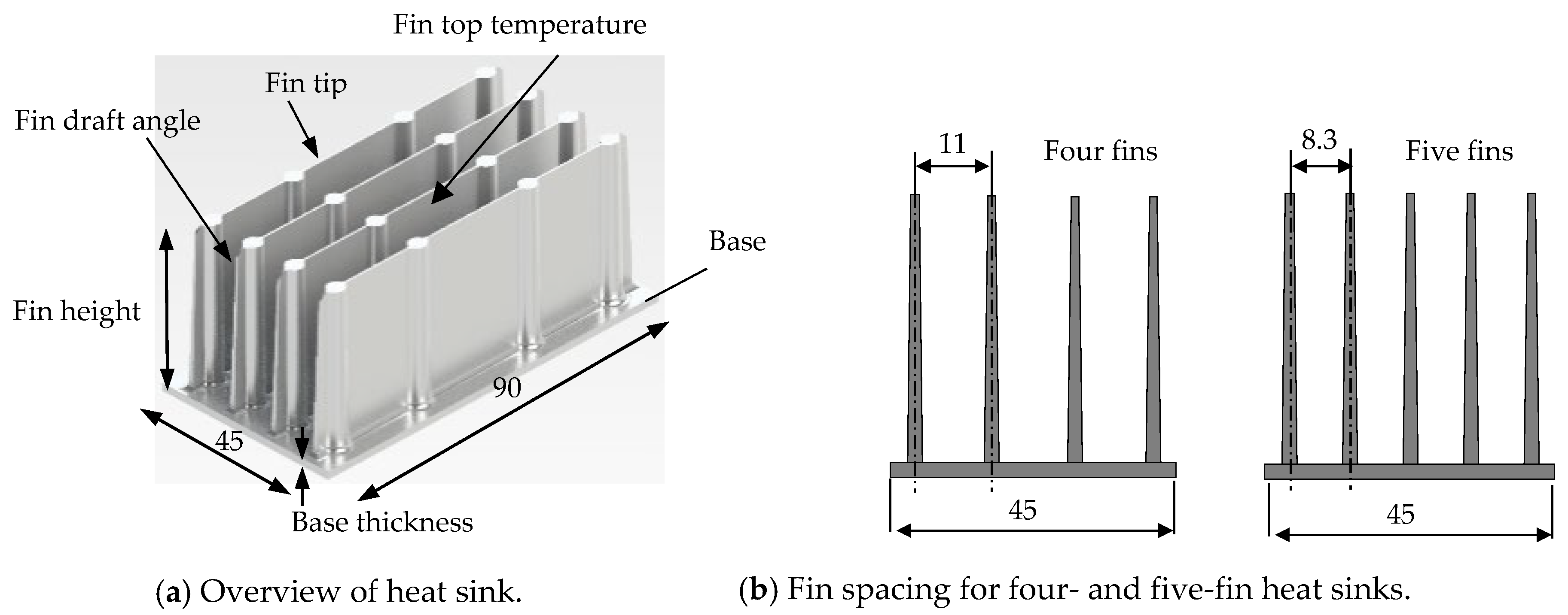
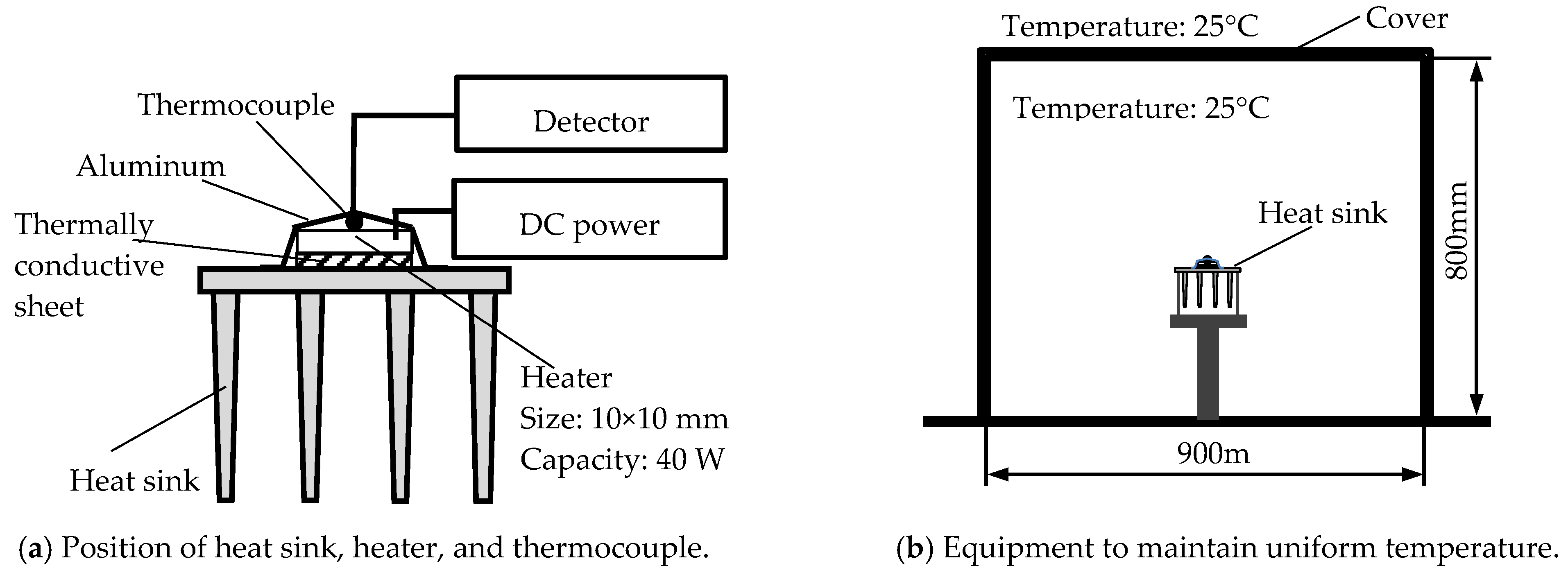
In this study, a 500 kN cold chamber die casting machine (HC 50F, Hishinuma machinery, Ranzan town, Saitama prefecture, Japan) with an injection power of 100 kN and a sleeve diameter of 45 mm was used [43]. The plunger speed was 0.8 m/s. The die temperature was set at 100 °C using a mold temperature controller (TT28, Hishinuma machinery, Ranzan town, Saitama prefecture, Japan) [44]. The chemical compositions of JIS ADC12 and Al-25%Si are summarized in Table 1. The thermal conductivities of ADC12 and Al-25%Si are 102 W/(m·K) and 127 W/(m·K), respectively. The liquidus temperatures for ADC12 and Al-25%Si were 580 and 760 °C, respectively, while the pouring temperatures were 650 and 830 °C, respectively. The aluminum alloy was melted in an oxidizing atmosphere using a gas furnace. The spiral die used to investigate the flow length features a channel width of 7 mm and channel gaps of 0.5 and 1.0 mm, as shown in Figure 1 [19]. The shape and name of each part of the heat sink are shown in Figure 2. The tested heat sinks had either four or five fins. Fin gaps in commercial heat sinks under natural convection range from 10 to 15 mm. In the present study, the fin gaps for the four- and five-fin heat sinks were 11 and 8.3 mm, respectively. Notably, the 8.3 mm fin gap is narrower than that for a conventional heat sink. The dimensions of the heat sinks are summarized in Table 2. A schematic illustration of the experimental apparatus for investigating heat dissipation is shown in Figure 3. The mounting method for the heater, thermocouple, detector, and aluminum sheet is shown in Figure 3a. The equipment to maintain temperature uniformity is shown in Figure 3b. A square-shaped micro-ceramic heater (MS-3, Sakaguchi, Akihabara, Tokyo, Japan) measuring 10 mm on each side was attached to the back of the heat sink and operated at 40 W. A DC stabilized power supply (PSF-400L2, Texio, Yokohama city, Kanagawa prefecture, Japan) was used to heat the micro-ceramic heater. A 0.5 mm thick thermal interface material sheet (EX20000C7, Dexerials, Shimotsuke city, Tochigi prefecture, Japan) was inserted between the heat sink and the micro-ceramic heater. The temperature of the micro-ceramic heater, defined as that 30 min after saturation, was measured using a T-type thermocouple.
The flow length of ADC12 and Al-25%Si was compared using spiral dies. Castings for flow length were conducted 20 times under each condition, and the average was used as the final value. Thirty heat sink units were cast for each condition, and three of these were chosen at random for heat dissipation tests. Heat dissipation tests were conducted three times for each of the three heat sinks, and the average was used as the final value. The castability of the heat sink with thin fins made from ADC12 and Al-25%Si was compared using three types of heat sinks, labeled type A, B, or C. The effect of thermal conductivity on heat dissipation was investigated using the type A and B heat sinks for both ADC12 and Al-25%Si, while the effect of fin thickness on heat dissipation was compared using the type B and C heat sinks. The effect of fin height on heat dissipation was investigated using heat sink types C to F. The temperatures of the heat sink fin tops for types C to F were also measured using the T-type thermocouple. The effect of fin number on heat dissipation was investigated using both four-fin (types D and F) and five-fin (types G, J, H and I) heat sinks. The effect of base thickness on heat dissipation was investigated for 2 mm (type F) and 4 mm (types K and L) base thicknesses. Since the weight decreases as the porosity increases, the effect of porosity on heat dissipation was investigated using type F heat sinks of different weights. It was anticipated that the difference between fin top temperatures would increase as the difference between the microstructures of the fins increased. The fin top temperature was measured, and the microstructure near the fin top was observed using optical microscopy. Variations in temperature and microstructure were observed at different distances from the gate of the die. The type C heat sink was vertically divided along the fins into three pieces corresponding to the left, middle, and right sections. The heat dissipation of the left and right sections was compared to investigate the effect of the microstructure on heat dissipation.
Additionally, for practical application of the Al-25%Si heat sink, the possibility of anodization treatment was tested, and the thickness of the film and infrared emissivity were measured. Finally, the weight and heat dissipation of the Al-25%Si heat sink were compared with those of two types of commercial heat sinks.

3. Results and Discussion

3.1. Comparison of Al-25%Si with ADC12

3.1.1. Flow Length of ADC12 and Al-25%Si

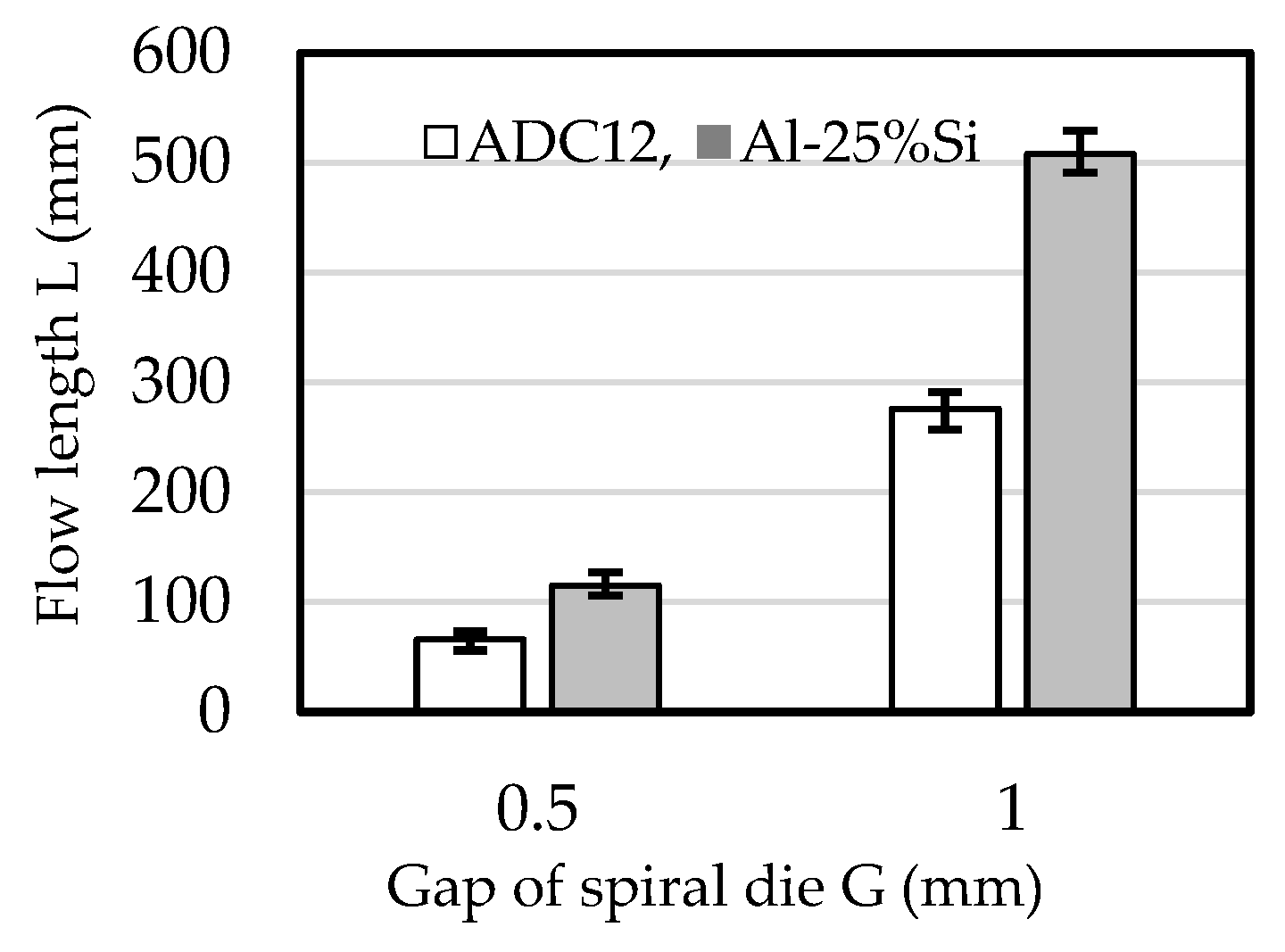
The flow lengths of ADC12 and Al-25%Si, measured using a spiral die, are shown in Figure 4. The flow length of Al-25%Si was 1.7 times longer than that of ADC12 for both 0.5 mm and 1 mm die gaps. ADC12 is an aluminum alloy commonly used for die casting owing to its good fluidity. However, the present results demonstrate that Al-25%Si has superior fluidity. Al-25%Si has notably higher latent heat than ADC12 due to its higher Si content [19]. As a result, the flow length of Al-25%Si is excellent and indicates potential for die casting of thin products.

3.1.2. Castability of ADC12 and Al-25%Si Thin Fins

The castability of thin fins using ADC12 and Al-25%Si was evaluated by casting type B, C, and F heat sinks, as summarized in Table 2. The results are shown in Figure 5. The type B heat sink was successfully cast using ADC12, but the type C heat sink exhibited unfilled areas near the top of the fins, as seen in Figure 5a,b. Conversely, the type B, C, and F heat sinks were all successfully cast using Al-25%Si, and the type F heat sink is shown in Figure 5c. The fin top thickness and draft angle for type C were half those for type B, and both had the same fin height of 35 mm. The thin fins of type C did not allow ADC12 molten metal to flow completely to the fin tops, resulting in unfilled sections at the tops of the fins. The fin top thicknesses and draft angles for the type C and F heat sinks were the same, while the fin heights were 35 mm and 50 mm, respectively. ADC12 molten metal could not fill the 35 mm height fins, but Al-25%Si molten metal could fill the 50 mm height fins. These results demonstrate that Al-25%Si has much better castability than ADC12 in the preparation of thin fins, making Al-25%Si especially suitable for casting tall and thin fins. This superior castability is due to the excellent flow length of the Al-25%Si, as shown in Figure 4.

3.1.3. Effect of Thermal Conductivity on Heat Dissipation

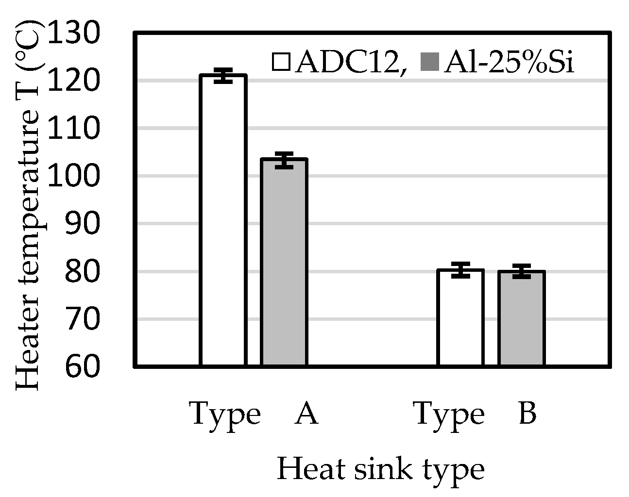
Al-25%Si has slightly higher thermal conductivity than ADC12. The effect of thermal conductivity on heat dissipation was investigated using ADC12 and Al-25%Si heat sinks. Types A and B were fabricated with fin heights of 20 and 35 mm, respectively. The results are shown in Figure 6. For the type A heat sink, the heater temperature was lower for the Al-25%Si heat sink than the ADC12 heat sink. It is thought that the difference in thermal conductivity influenced this result. In the type B heat sink, the heater temperatures were almost the same for both the ADC12 and Al-25%Si heat sinks. This result indicates that the effect of thermal conductivity on heat dissipation decreases as the fin height increases. The reason for this is not clear at this stage. It might be possible to choose aluminum alloys without focusing on thermal conductivity when the fin height is higher than 35 mm.

3.2. Effect of Fin Thickness on Heat Dissipation

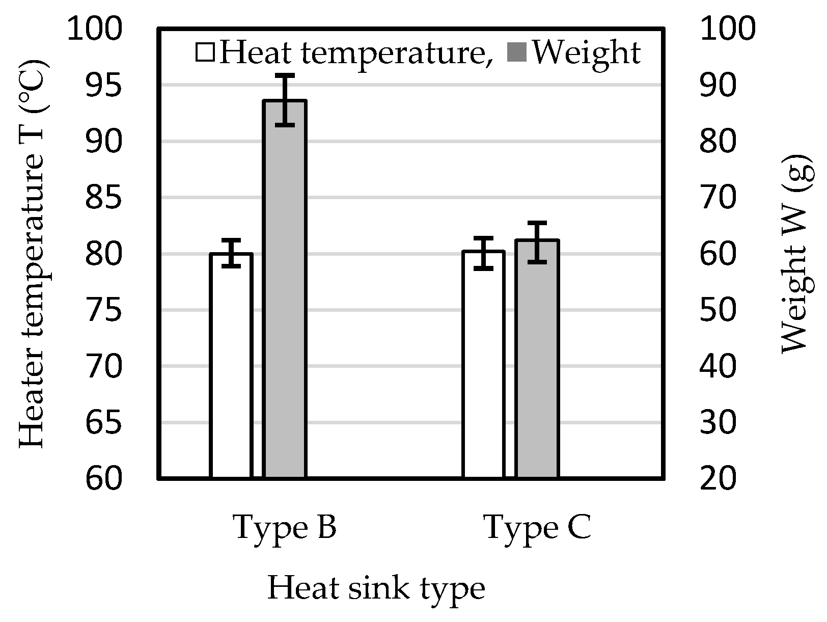
The effect of fin thickness on heat dissipation was investigated using the type B and C heat sinks made of Al-25%Si. The fin top temperatures were also measured. The results, including heater temperature and heat sink weight, are shown in Figure 7. The fin thickness did not significantly affect the heater temperature, indicating that heat dissipation is not influenced by fin thickness when the fins are as thin as those in the present study. As the fin thickness was decreased, the weight of the heat sink also decreased, suggesting that it is possible to reduce the weight of the heat sink without compromising its thermal performance.
The fin top temperatures for the type B and C heat sinks are shown in Figure 8. The fin top temperature was about 5 °C lower for the type C than for the type B heat sink. The fin top thickness for type C was half that for type B. The heat capacity of the fins was lower in the type C than in the type B heat sink, which may explain the lower top fin temperature in type C. The effect of fin top temperature on heater temperature appears to be minimal.

3.3. Effect of Fin Height on Heat Dissipation

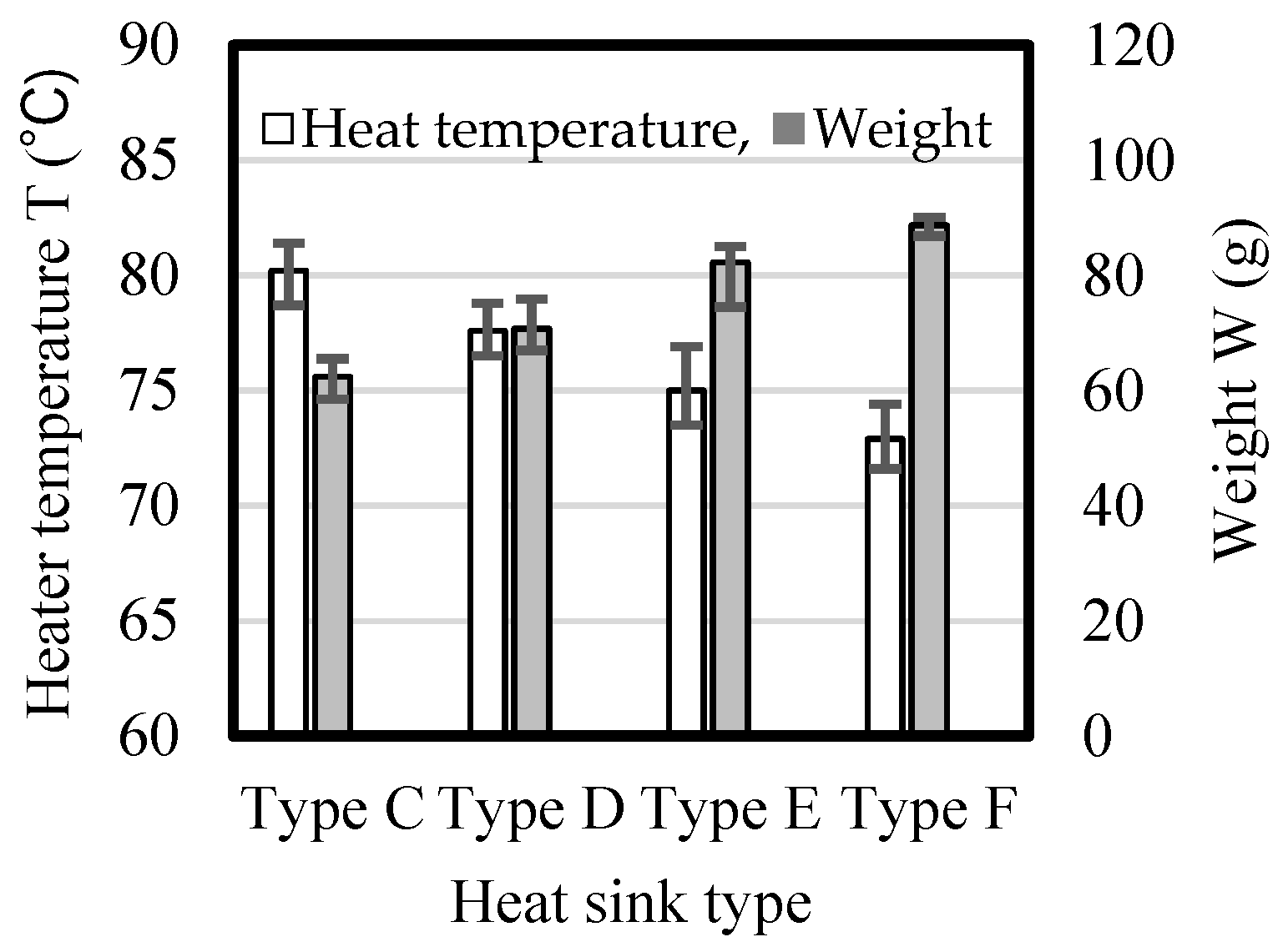
The effect of the fin height on heater temperature and weight is shown in Figure 9. The heater temperature decreased as the fin height increased, likely due to an increase in the heat dissipation area, which in turn reduced the heater temperature. The heater temperature was about 7 °C lower for the type F than that for the type C heat sink. An increase of 15 mm in fin height contributed to a 9.3% decrease in heater temperature.
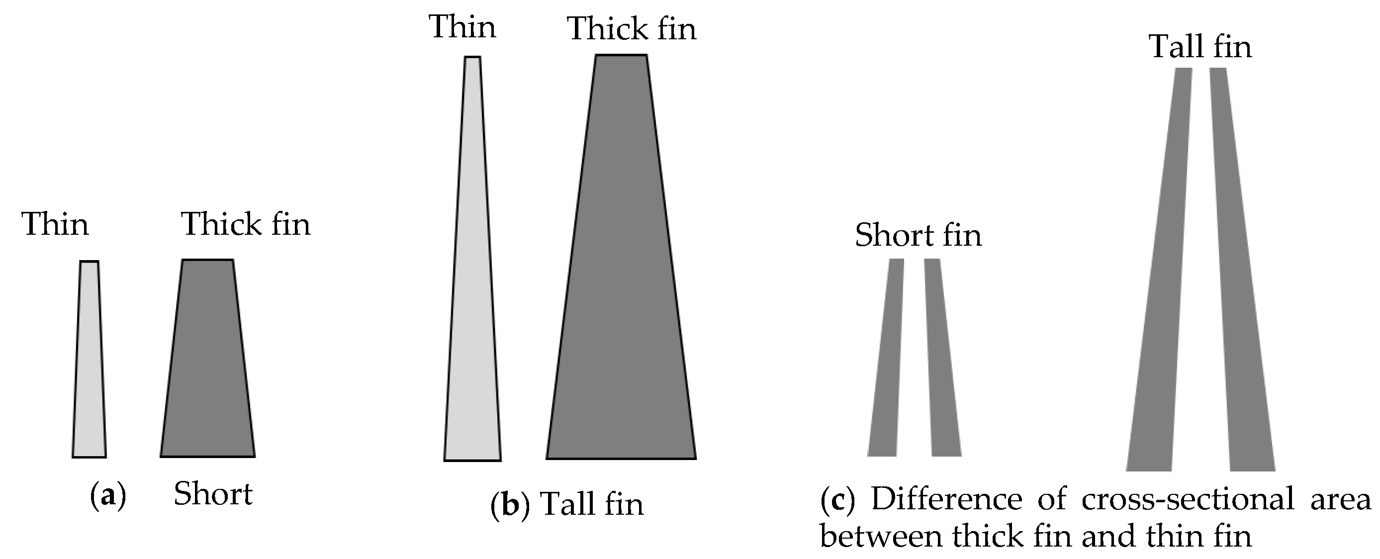
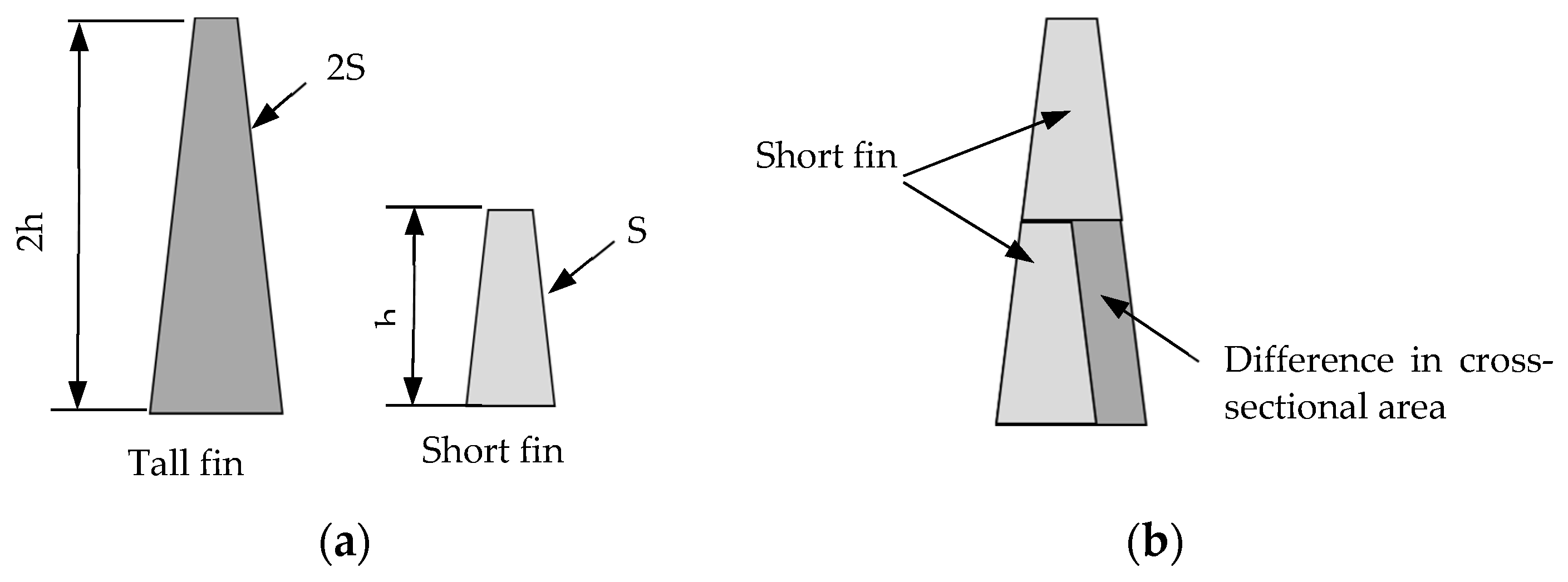
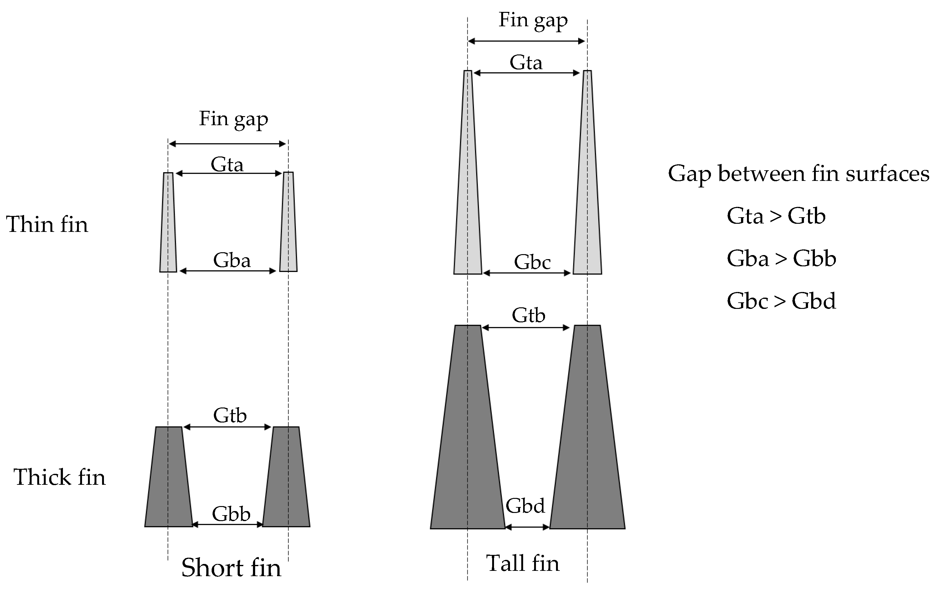
The weight increase from the type C to the type F heat sink was 26.4 g, which represents 42.3% of the weight of the type C heat sink, with the base thickness remaining the same at 2 mm. This increase in weight is thus attributed to the increase in the weight of the fins. As the fin height increased, the proportion of the fin weight in the total heat sink weight also increased. This means that in heat sinks with tall fins, decreasing fin thickness is useful for reducing weight. Differences in the cross-sectional area between thin and thick fins with different fin heights are shown schematically in Figure 10. The draft angle was greater for the thick fin than for the thin fin. Cross-sections of short and tall fins are shown in Figure 10a,b, respectively. The difference in cross-sectional area at different heights between thin and thick fins increased with fin height, as shown in Figure 10c. This demonstrates that the difference in fin weight increased as the fin height increased. Therefore, the effectiveness of thin fins and small draft angles in reducing heat sink weight increases with fin height.
Under conditions of constant weight, the fin height decreased as the fin thickness increased. The heat dissipation also increased as the fin height increased, which suggests that a heat sink with thin fins can both be lightweight and achieve good thermal performance. This demonstrates the importance of fin thinness in the design of lightweight heat sinks.
The effect of the fin height on the fin top temperature is shown in Figure 11. As the fin height increased, the fin top temperature decreased. It is thought that the increased distance from the heater to the fin top and the larger fin area resulted in a lower fin top temperature. Tall fins may also be more suitable for fire prevention.

3.4. Effect of Fin Number on Heat Dissipation

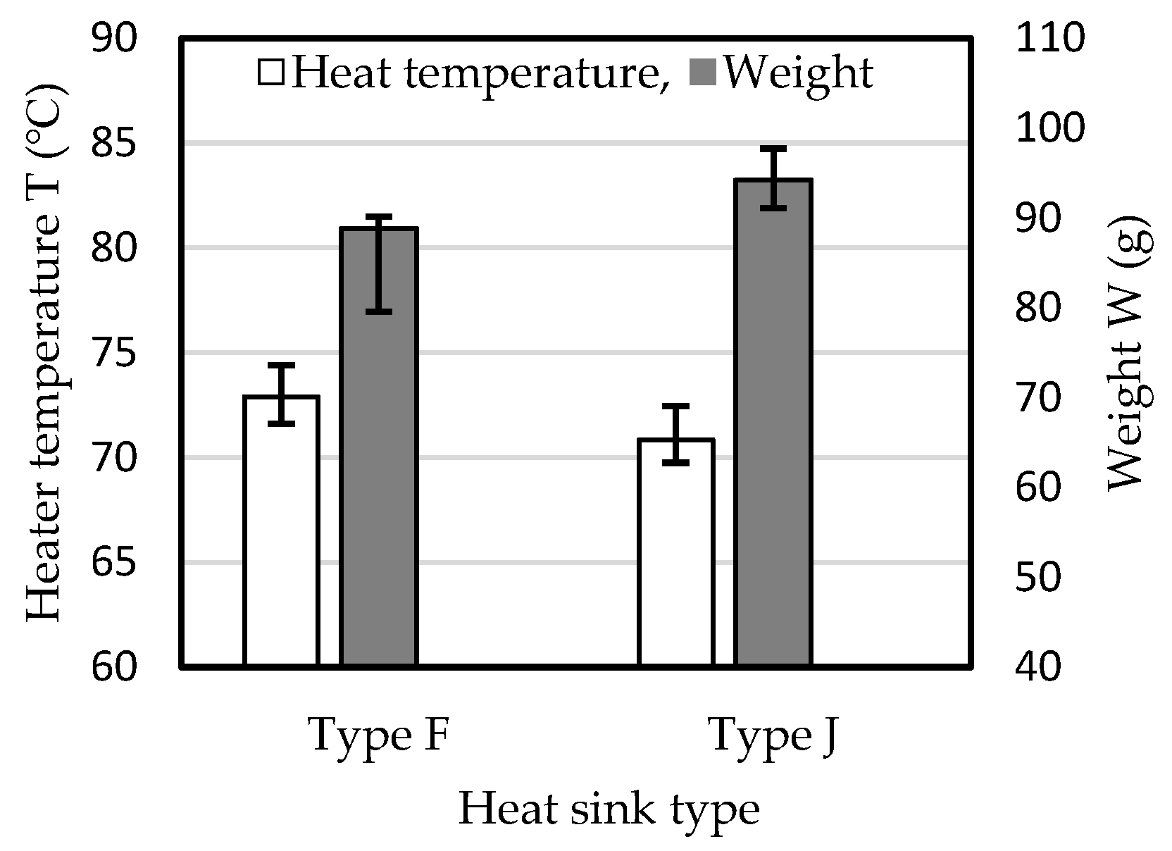
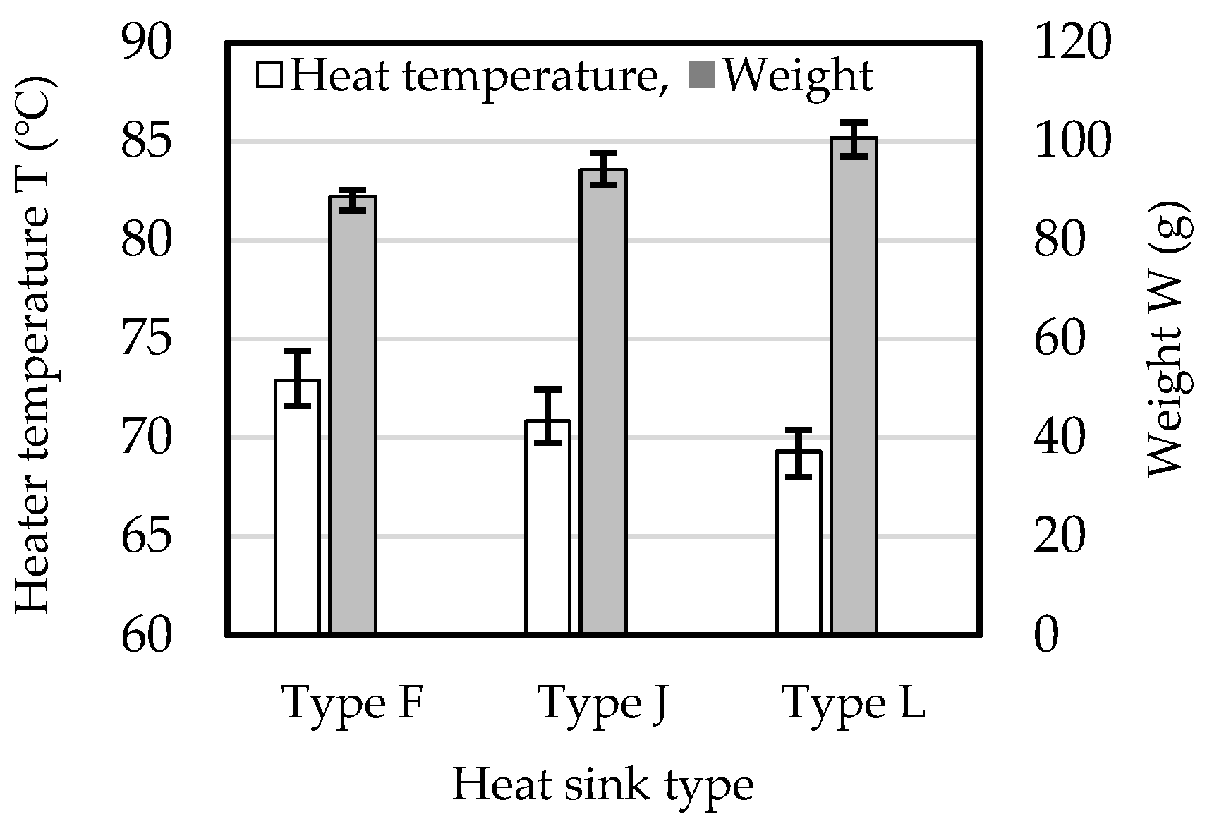
The effect of fin number on heat dissipation was investigated under three different conditions: constant fin height, constant fin area, and constant weight. The effect of fin number on heater temperature and weight with a constant fin height of 50 mm is shown in Figure 12. The fin numbers for type F and J heat sinks were 4 and 5, respectively. The heater temperature was about 2 °C lower for the type J than for the type F heat sink, which demonstrates the effect of increased heat dissipation area. However, the weight of the type J heat sink was about 15 g higher than the type F heat sink due to the additional fin. When space is limited, increasing the fin number is an effective strategy for enhancing heat dissipation in heat sinks.
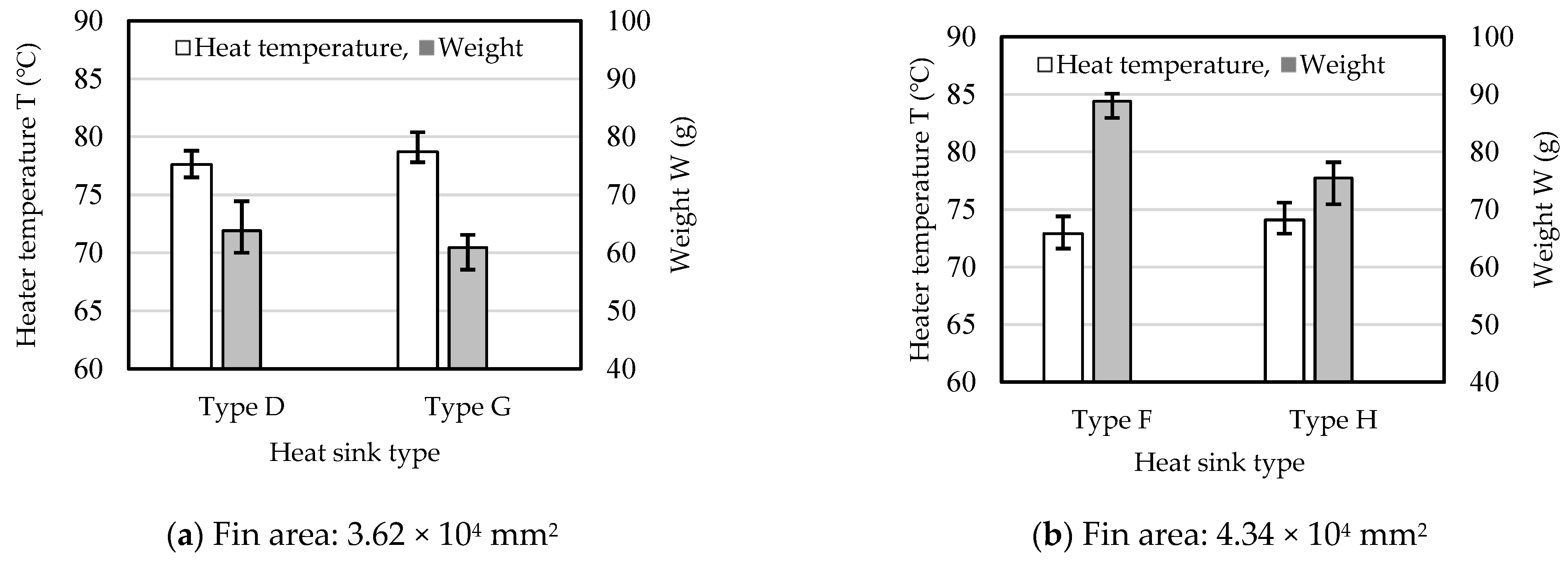
Heat dissipation comparisons between four- and five-fin heat sinks were conducted for the same fin area. The results are shown in Figure 13. The fin areas in Figure 13a,b are 3.62 × 104 mm2 and 4.34 × 104 mm2, respectively, showing that fin area increased due to increased fin height. In Figure 13a,b, the four-fin heat sink has a lower heater temperature than the five-fin heat sink, and the five-fin heat sink has a lower weight than the four-fin heat sink. As the fin number increased, the fin gap decreased, and the space between fins decreased while the width of the base remained constant. Air convection deteriorated as the space between fins decreased, leading to higher air temperatures. Therefore, the average heat transfer coefficient between the fins and the air decreased as the space between fins decreased [37]. Consequently, the five-fin heat sink was found to have lower heat dissipation than the four-fin heat sink.
The cross-section of the fin in the height direction is trapezoidal, with the fin thickness increasing closer to the base, as shown in Figure 14. The tall fin, which has double the surface area and height of the short fin, is shown in comparison to the short fin in Figure 14a. The cross-sectional area of the tall fin is larger than the sum of that for two short fins, as shown in Figure 14b. This means that the weight of one tall fin is larger than the combined weight of two short fins. Consequently, the weight of the four-fin heat sink is larger than that of the five-fin heat sink when the fin area is the same. The difference in cross-sectional area decreases as the draft angle decreases, meaning that the difference in weight also decreases as the draft angle is reduced.
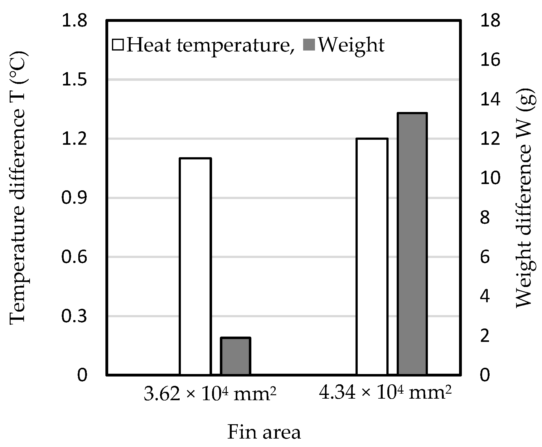
Differences in heater temperature and weight between the four- and five-fin heat sinks for each fin area are shown in Figure 13 and Figure 15. The differences in heater temperature and weight between the four- and five-fin heat sink increased as the fin area increased. As the fin area was increased, the heater temperature remained higher for the five-fin heat sink than for the four-fin heat sink. Conversely, the four-fin heat sink had a higher weight than that for the five-fin heat sink as the fin area was increased. As the fin height increased, the gap between fin surfaces at the bottom decreased. The gap between fin surfaces was narrower for the five-fin than for the four-fin heat sink. Air convection worsened as the gap between the fins decreased and the fin height increased, resulting in an increase in air temperature [21]. The effect of fin height on the reduction of air convection was remarkable as the gap between fin surfaces decreased. According to this mechanism, the difference in the heater temperature between the four- and five-fin heat sinks expanded as the fin height increased.
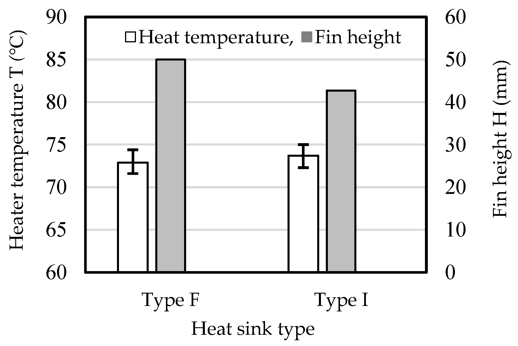
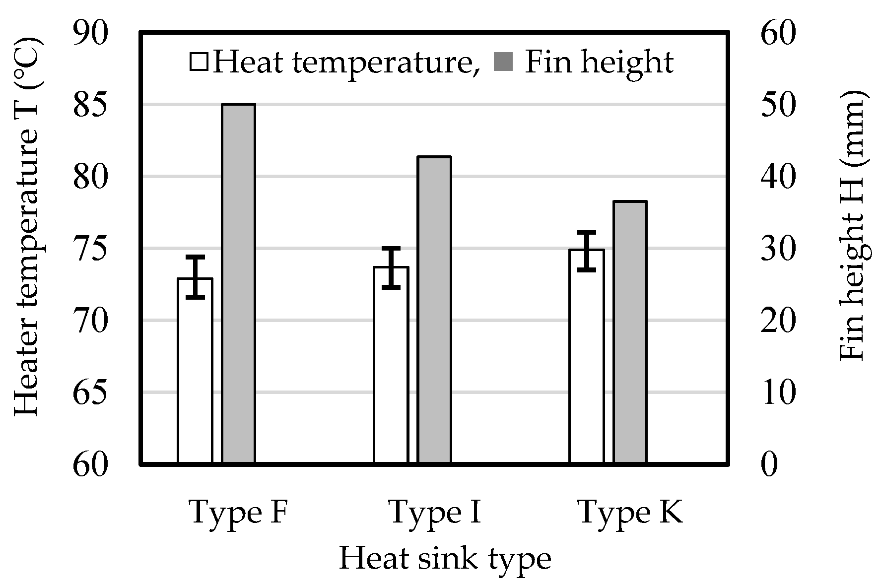
The effect of fin number on heat dissipation was investigated while maintaining the same heat sink weight of 88.8 g. Heater temperatures and fin heights are shown in Figure 16. The type F heat sink had four fins, each with a height of 50 mm, whereas the type I heat sink had five fins, each with a height of 42.7 mm. The type I heat sink had a 1.76 × 103 mm higher fin area than the type F heat sink. The heater temperatures for the type F and I heat sinks were 72.9 and 73.7 °C, respectively. Under the condition of constant base size and weight, an increase in fin number did not effectively increase heat dissipation, as judged from Figure 15. Instead, increasing the fin height appeared to be more effective than increasing the fin number for enhancing heat dissipation. In other words, taller fins are more effective at increasing heat dissipation.
Air convection between fins also greatly influenced heat dissipation by the heat sink. Convection decreased as the fin gap decreased and the fin height increased. Comparisons between thinner and thicker fins for the same fin gap are shown in Figure 17. The fin top thickness and draft angle were greater for the thicker fin than for the thinner fin. The space between fins increased as both the fin top thickness and draft angle decreased for a constant fin gap, as shown in Figure 17. Given the same fin gap, fin number, and fin height, a heat sink with thinner fins has better air convection than a heat sink with thicker fins. The advantage of thinner fins becomes greater as the fin height increases, as judged from the space between fins.

3.5. Effect of Base Thickness on Heat Dissipation

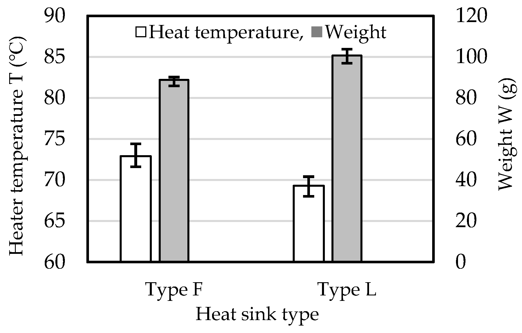
The effect of base thickness on the heater temperature for Al-25%Si heat sinks with thin fins was investigated. The empirical evidence suggests that the heat dissipation increased as the base thickness increased. In conventional die-cast heat sinks used under natural convection conditions, the base thickness ranges from 4 to 8 mm. However, the present study is focused on investigating the properties of lightweight heat sinks with thin fins. The base thicknesses for the type F and L heat sinks were 2 and 4 mm, respectively, thinner than the base of conventional heat sinks. The heater temperature and weight are shown in Figure 18. Both type F and L heat sinks had a fin height of 50 mm. The type L heat sink had a lower heater temperature than the type F heat sink, indicating that a thicker base is useful for enhancing heat dissipation in heat sinks with thin fins. This result is aligned with empirical conventional knowledge on heat sink design. The type L heat sink was 25% higher in weight than the type F heat sink due to its thicker base. In heat sinks with thin fins, the base contributes a larger percentage to the overall weight compared to heat sinks with thick fins. When the fin height cannot be further increased due to limitations, increasing the base thickness is a useful strategy for enhancing the heat dissipation of the heat sink.
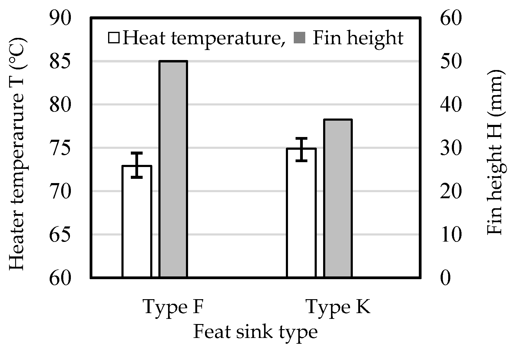
The effect of the base thickness on heat dissipation was investigated for the same weight of 79.5 g. The base thickness and fin height for the type F heat sink were 2 and 50 mm, respectively, while those for the type K heat sink were 4 and 36.5 mm, respectively. Heater temperatures and fin heights are shown in Figure 19. The type F heat sink had a 2 °C lower heater temperature than the type K heat sink. Although a thicker base is normally advantageous in terms of heat dissipation, this was canceled out by the decreased fin height. Under situations of weight constraints, fin height is more effective than base thickness for improving heat dissipation.
The effects of the fin height, fin number, and base thickness on heat dissipation were compared under two conditions: constant fin height and constant weight. In Figure 20, it is shown that the fin heights for three types of heat sinks were kept at 50 mm. The fin numbers for the type F, J, and L heat sinks were 4, 5, and 4, respectively, while their base thicknesses were 2 mm for both types F and J and 4 mm for type L. For the same fin height, the base thickness (type L heat sink) had a greater effect on the heater temperature than the fin number (type J heat sink). The type L heat sink was also higher in weight than the type J heat sink. Increasing the fin number from 4 to 5 in type L would decrease the heater temperature further, but also result in increased weight. This demonstrates that, for a constant fin height, an increase in weight is required to enhance heat dissipation.
Next, at a common weight of 79.5 g, the effects of the fin height, fin number, and base thickness on heat dissipation were compared. The fin heights for the type F, I, and K heat sinks were 50, 42.7, and 36.5 mm, respectively. The fin numbers for the type F, I, and K heat sinks were 4, 5, and 4, respectively, and the base thicknesses were 2 mm for types F and I and 4 mm for type K. The heater temperatures and fin heights for these three types of heat sinks are shown in Figure 21. The heater temperatures for the type F, I, and K heat sinks were 72.9, 73.7, and 74.9 °C, respectively. The heater temperature decreased as the fin height increased. In heat sinks with thin fins, like those in the present study, increasing the fin height under constant weight conditions may be an important factor in enhancing heat dissipation.

3.6. Effect of Porosity and Microstructure Non-Uniformity on Heat Dissipation

Porosity is common in products manufactured using die casting. Porosities in a heat sink observed using X-ray computed tomography scans are shown in Figure 22. Figure 22 shows examples of the shape, size, and position of such porosities, which may not be consistent across heat sinks cast under the same conditions. Porosity has been reported to negatively impact thermal conductivity and, consequently, the heat dissipation of the heat sink [9]. It is very difficult to precisely measure all pore sizes, but it is thought that there is a relationship between the weight of the heat sink and the porosity; specifically, the weight decreases as the porosity increases. In the present study, the effect of porosity on heat dissipation was evaluated by comparing heater temperatures for heat sinks with different weights of 79.5 and 90.1 g. The estimated difference in the porosity derived from the weight difference was about 4 × 103 mm3. Heater temperatures are presented in Figure 23, showing that they were almost the same for heat sinks of different weights. This suggests that porosity has a very small effect on heat dissipation, although the reasons for this are not clear. It is estimated that uneven heat dispersion caused by porosity in the die-cast Al-25%Si heat sink is minimal.
The non-uniformity of the microstructure in a single die-cast product can also affect heat dissipation. The effect of microstructural non-uniformity on thermal conductivity was investigated in an Al-25%Si heat sink [41], with measurement of differences in heat dissipation across the different parts.
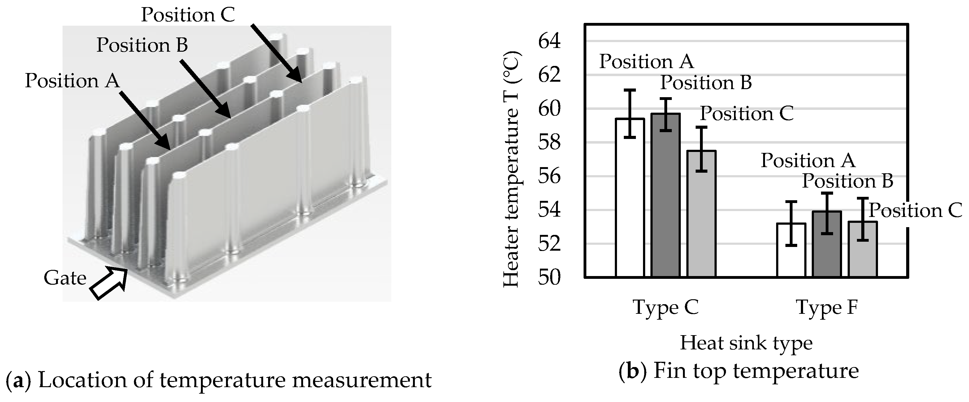
No clear relationship was found between fin height and non-uniformity of the microstructure. Fin top temperatures were measured for the type C and F heat sinks. The position of temperature measurement and the resulting fin top temperatures are shown in Figure 24. The temperature difference between positions A and B, as shown in Figure 24a, was larger in the type C heat sink (fin height: 35 mm) than in the type F heat sink (fin height: 50 mm), as shown in Figure 24b. This indicates that variations in microstructure may contribute to differences in fin top temperatures.
The microstructure at the fin tops of the type C heat sink was observed using optical microscopy, as shown in Figure 25. Positions A, B, and C correspond to Figure 24a. It can be seen that both the number and size of primary Si particles, both inside and on the surface of the fin tops, increased from position A to C, while the amount of α-Al decreased from position A to position C. The degree of eutectic structure also decreased from position A to C, suggestive of an increase in Si content toward position C. The molten metal flow within the die was estimated, as shown in Figure 26. The temperature, flow speed, and Si content of the molten metal possibly decreased from position C to A. The molten metal temperature decreased from position C to A. It is thought that more primary Si crystallized at position C, while α-Al crystallized as the temperature decreased. This order of flow might determine the non-uniformity observed in the microstructure. Whether the narrow gap in the die may contribute to the non-uniformity of the microstructure remains unclear.
Next, the type C heat sink was cut into three pieces as shown in Figure 27a,b, and the heat dissipation of parts A and C was compared. The heat dissipation was measured using the method shown in Figure 2. The heater output was set at 9 W to accommodate the reduced size of the heat sink parts. Despite the microstructural differences between parts A and C, the heater temperatures were almost the same, as shown in Figure 27c. This outcome suggests that the heat dissipation may not be affected by the microstructural differences shown in Figure 25. Judging from Figure 25 and Figure 27c, the effect of microstructural non-uniformity on heat dissipation for the Al-25%Si heat sink is negligible.

4. Investigation for Practical Use

4.1. Anodization

Anodization treatment is useful for increasing infrared emissivity [45]. The feasibility of applying anodization treatment to Al-25%Si heat sinks was investigated. The results for the anodization process are shown in Figure 28. The treatment was successfully applied to the Al-25%Si heat sinks, producing oxide films with thicknesses of 12 to 25 μm. The resulting infrared emissivity was 0.94, which is sufficiently high for practical use.

4.2. Comparison of Heat Dissipation between Al-25%Si Heat Sink and a Commercial Heat Sink

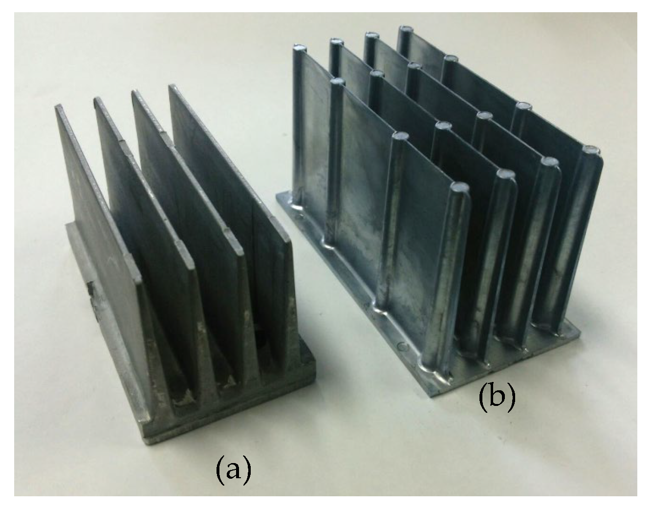
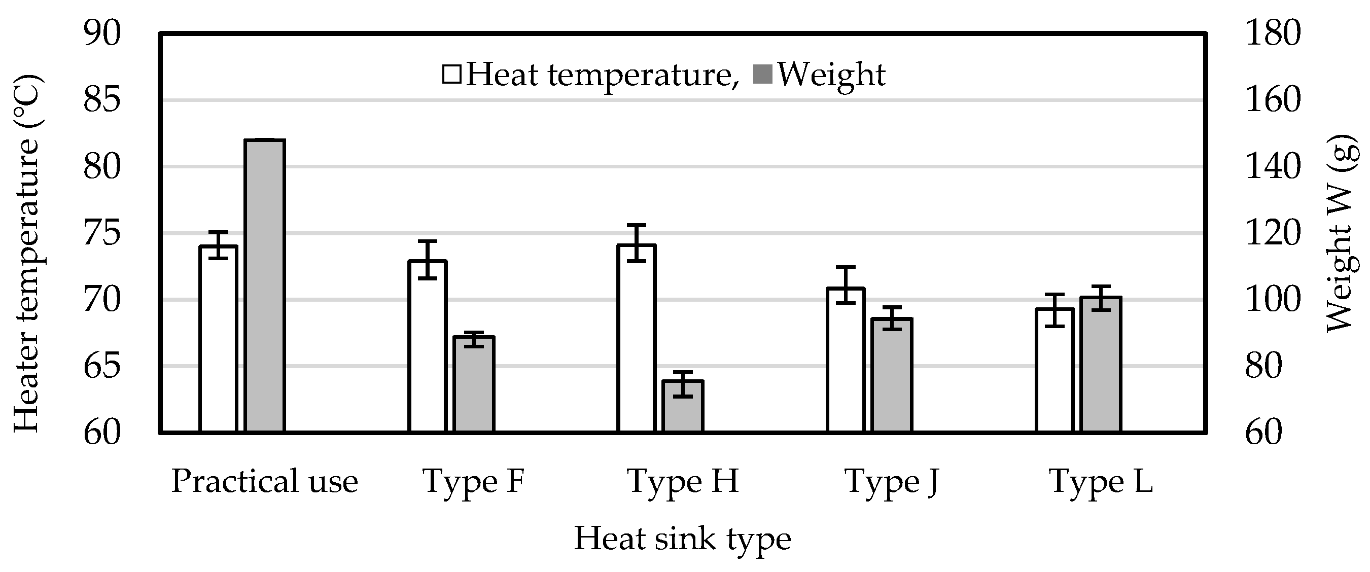
In this study, the heat dissipation and weight of a commercial heat sink and the fabricated Al-25%Si heat sink were compared. A commercial heat sink with a similar base size to the heat sink in this study was chosen for comparison. Details, including a photograph of the heat sinks and a comparison of their size, are given in Figure 29 and Table 3. The results of the heater temperature and weight are shown in Figure 30. The chosen heat sinks fabricated in this study, which featured equal or lower heater temperatures compared to commercial heat sinks, showed notable improvements. Due to the excellent fluidity of Al-25%Si, reductions in fin top thickness, draft angle, and base thickness were possible while enabling an increase in fin height without adding weight. These results demonstrate that Al-25%Si heat sinks have advantages over commercial heat sinks in terms of weight reduction. The weights of the type H and L heat sinks were 51% and 68% of the weight of the commercial heat sink, respectively.
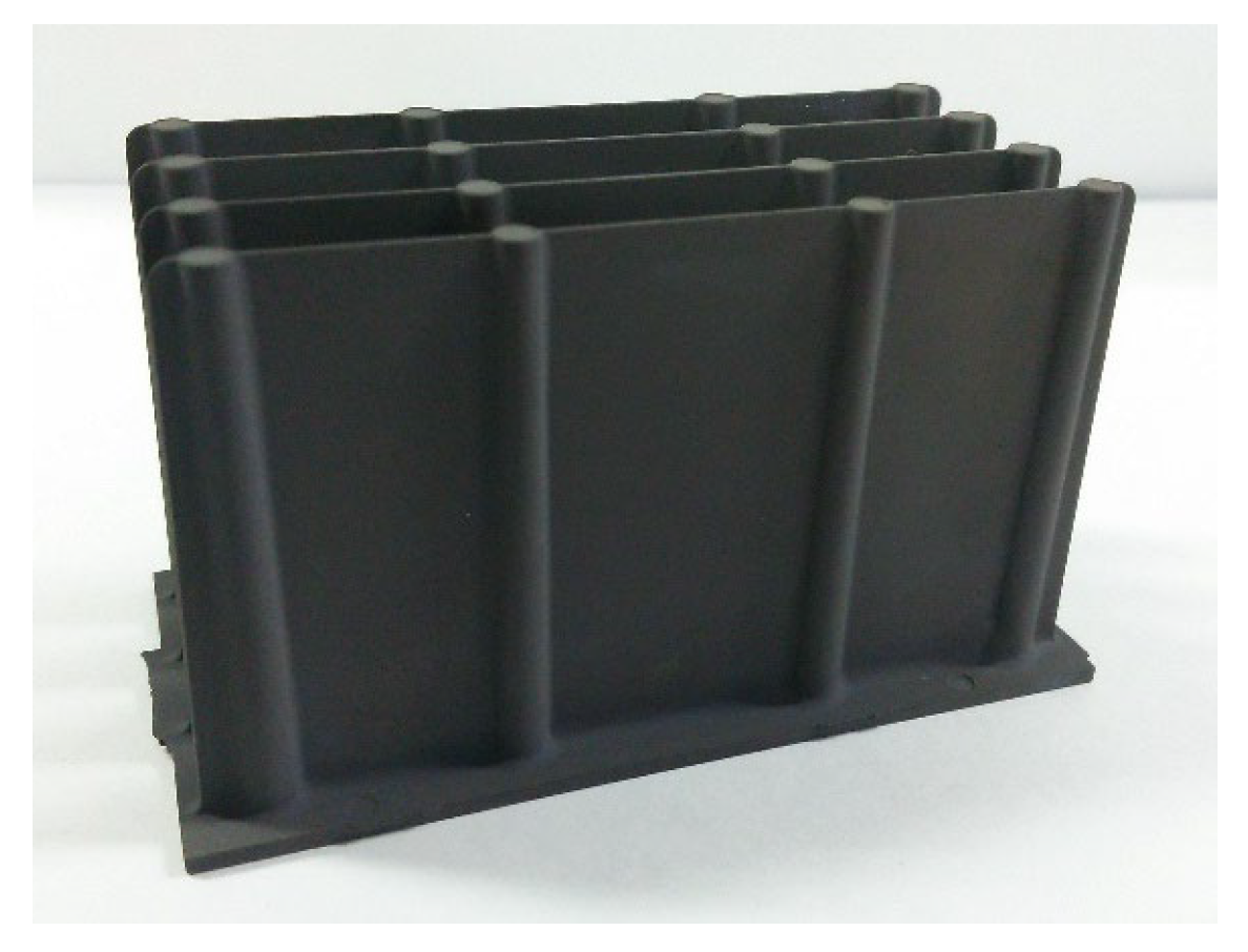
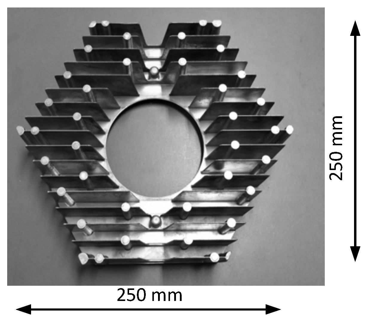
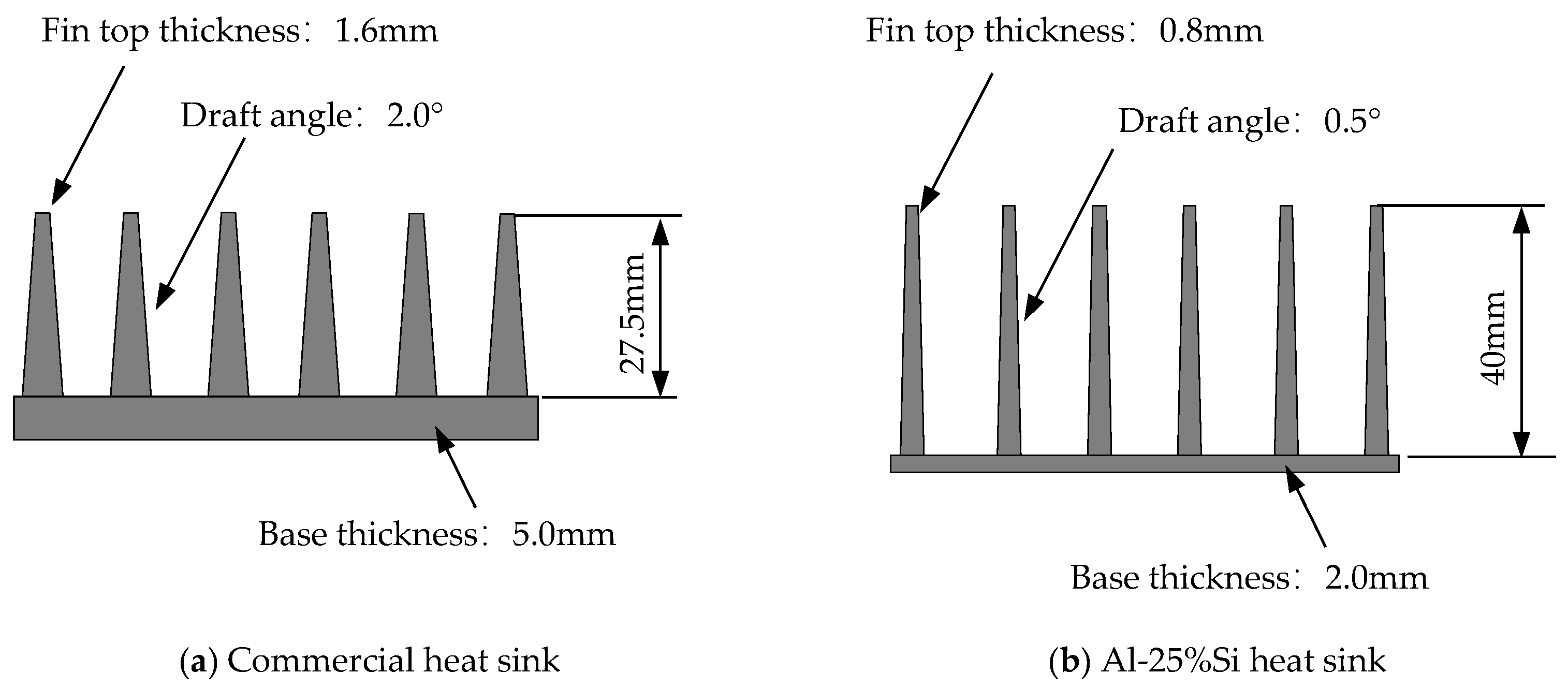
Furthermore, casting of a LED lamp heat sink for high ceilings was trialed using Al-25%Si, with comparison to a commercial heat sink in terms of both heat dissipation and weight. A photograph of the Al-25%Si heat sink is shown in Figure 31. It was possible to cast a large-sized heat sink using Al-25%Si. Comparisons of fin size and base thickness for the commercial heat sink and that fabricated in this study are shown in Figure 32. The heat sink in this study showed slightly improved heat dissipation compared to the commercial heat sink. The weights of the commercial heat sink and that fabricated in this study were 1200 g and 780 g, respectively. Overall, a 35% reduction in weight was attained through the use of thin fins and a thin base.

5. Conclusions

The demand for lightweight heat sinks is growing. There are two main ways to reduce the weight of heat sinks. The first approach involves enhancing heat dissipation and downsizing the heat sink. However, materials with excellent heat dissipation properties are generally expensive, and special processing may be necessary to manufacture the heat sink from these non-standard materials, potentially increasing overall costs. The second approach involves thinning the fins and the base of the heat sink. Heat sinks are typically made from aluminum alloys using die casting, a method that is normally economical. To successfully produce thinner products, the use of an aluminum alloy with excellent fluidity is needed. In the present study, Al-25%Si was selected for its exceptional fluidity. Al-Si alloys are among the most popular aluminum alloys, and the addition of expensive elements is not needed, making Al-25%Si a cost-effective option. In our experiments, we focused on using Al-25%Si with a conventional die casting machine to create a lightweight heat sink with thin fins and a thin base.
First, the fluidity of Al-25%Si was compared with that of JIS ADC12, which is a conventional aluminum alloy for die casting, using a spiral die with 0.5 mm and 1 mm gaps. The results demonstrate that the flow length was significantly longer for Al-25%Si than for ADC12. The castability of Al-25%Si was then compared with that of ADC12 based on the production of thin fins. It was clear that Al-25%Si can be effectively cast to produce heat sinks with a fin top thickness of 0.5 mm, a fin draft angle of 0.5°, a fin height of 50 mm, and a base thickness of 2 mm. Notably, the fin top thickness and draft angle of conventional heat sinks are usually larger than 1 mm and 1°, respectively. Thus, reductions in the fin top thickness and draft angle were successfully realized. Our findings also reveal that fin thickness does not affect heat dissipation by the heat sink. This shows that it is possible to reduce the heat sink weight by reducing the fin thickness without compromising heat dissipation.
The properties of the Al-25%Si heat sink with thin fins were elucidated. The effects of fin height, fin number, and base thickness on heat dissipation were investigated using Al-25%Si heat sinks with a fin top thickness of 0.5 mm and a draft angle of 0.5°. It was observed that heat dissipation increased when the fin height, fin number, and base thickness increased. The effects of these factors on the heat dissipation were also investigated for constant weight, and it became clear that, of these factors, increasing the fin height was most effective for enhancing heat dissipation. This result indicates that thinner fins are useful for optimizing the heat dissipation of lightweight heat sinks without adding weight.
Additionally, anodization treatment was applied to the Al-25%Si heat sink to increase infrared emissivity, achieving an emissivity value of 0.94.
The thermal performances of a commercial heat sink and the Al-25%Si heat sink were compared. It was possible to cast a large-sized heat sink for high-ceiling LED lamps using Al-25%Si, and the weight could be reduced while maintaining a similar heat dissipation performance. These findings demonstrate that tall and thin fins are effective for reducing heat sink weight without negatively impacting heat dissipation, and that Al-25%Si is especially useful for realizing such fins in the present heat sink design.

Author Contributions

Conceptualization, T.H.; methodology, H.F. and T.H.; validation, H.F. and T.H.; formal analysis, H.F. and T.H.; investigation, H.F. and T.H.; resources, T.H.; data curation, H.F. and T.H.; writing—original draft preparation, H.F. and T.H.; writing—review and editing, H.F. and T.H.; visualization, H.F. and T.H.; supervision, T.H.; project administration, T.H.; funding acquisition, T.H. All authors have read and agreed to the published version of the manuscript.

Funding

This research was supported Adaptable and Seamless Technology Transfer Program through Target-Driven R&D Feasibility Study Stage Exploratory Research (AS232Z02219B, VP29117939183) from Japan Science and Technology Agency (JST).

Data Availability Statement

The original contributions presented in the study are included in the article, further inquiries can be directed to the corresponding author.

Conflicts of Interest

The authors declare no conflicts of interest.

References

  1. Car LED Lamp Heat Sink. Available online: https://www.nikkeikinholdings.co.jp/car/detail/a0180.html (accessed on 29 March 2024).
  2. Car LED Lamp Heat Sink. Available online: http://www.nanshin-grp.co.jp/car_product/ (accessed on 29 March 2024).
  3. High-Ceiling LED Lamp Heat Sink. Available online: http://ja.perfumecaps.com (accessed on 29 March 2024).
  4. Şevik, S.; Őzdilli, Ő.; Akbulut, F. Numerical investigation of the effect of different heat sink fin structures on the thermal performance of automotive LED headlights. Int. J. Automot. Sci. Technol. 2022, 6, 17–126. [Google Scholar] [CrossRef]
  5. Stafford, J.; Walsh, E.; Egn, V.; Walsh, P.; Muzychka, Y.S. A novel Approach to Low Profile Heat Sink Design. J. Heat Transf. 2010, 132, 091401. [Google Scholar] [CrossRef]
  6. Kim, E.J.; Kim, D.K.; Oh, H.H. Comparison of Fluid Flow and Thermal Characteristics of Plate-Fin and Pin-Fin Heat Sinks Subject to Parallel Flow. Heat Transf. Eng. 2008, 29, 169–177. [Google Scholar] [CrossRef]
  7. Mallikarjuna, V.; Rajesh, K.; Ramesh, K.; Reddy, B.R.B. Modeling and Optimization of shape of a Heat Sink Fins on Motherboard. J. Comput. Math. Sci. 2015, 65, 228–251. [Google Scholar]
  8. Kappranos, P. Current State of Semi-Solid Net-Shape Die Casting. Metals 2019, 9, 1301. [Google Scholar] [CrossRef]
  9. See, A.; Caporale, L. High Density Die Casting (HDDC): New frontiers in the manufacturing of heat sinks. J. Phys. Conf. Ser. 2014, 525, 012020. [Google Scholar] [CrossRef]
  10. Jou, R.Y. Thermal analysis of LED Heat Sinks by High-Vacuum Die Casting (HVDC). Adv. Sci. Lett. 2012, 8, 421–426. [Google Scholar] [CrossRef]
  11. Wu, N.; Sun, M.; Guo, H.; Zie, Z.; Du, S. Enhancement effect of a diamond network on the flow boiling heat transfer characteristics of a diamond/Cu heat Sink. Energies 2023, 16, 7228. [Google Scholar] [CrossRef]
  12. Maiorano, L.P.; Castillo, R.; Molina, J.M. Al/Gf composite foams with SiC-engineered interfaces for the next generation of active heat dissipation materials. Compos. Part A 2023, 166, 107367. [Google Scholar] [CrossRef]
  13. Khan, M.A.; Ali, H.M.; Rehman, T.; Arsalanloo, A.; Niyas, H. Composite pin-fin for effective hotspot reduction. Heat Trans. 2024, 53, 1816–1838. [Google Scholar] [CrossRef]
  14. Li, H.; Ding, L.; Li, J.; Fang, Y.; Li, G.; Shi, Y.; Zhang, Z.; Li, L. Progress in preparation of silicon carbide particulate copper composites. Shandong Chem. Ind. 2021, 50, 65–67. [Google Scholar]
  15. Chen, Z.; Liu, C.; Xie, Y.; Pan, Z.; Ren, S.; Qu, X. Preparation and research process of high thermal conductivity metal matrix composites. Powder Metall. Technol. 2022, 40, 40–52. [Google Scholar]
  16. Coia, P.; Dharmasiri, B.; Stojcevski, F.; Hayne, D.J.; Austria, E., Jr.; Akhavan, B.; Razal, J.M.; Usman, K.A.S.; Stanfield, M.K.; Henderson, L.C. Scalable electrochemical grafting of anthraquinone for fabrication of multifunctional carbon fibers. L. JMST 2024, 200, 162–175. [Google Scholar] [CrossRef]
  17. Gupta, M.K. Mechanical behaviors of Al6063/TiB2 composites fabricated by stir casting process. Mater. Today Proc. 2023, 82, 222–226. [Google Scholar] [CrossRef]
  18. Zasadzińska, M.; Strzępek, P.; Mamala, A.; Noga, P. Reinforcement of aluminium-matrix composites with glass fibre by metallurgical synthesis. Materials 2020, 13, 5441. [Google Scholar] [CrossRef]
  19. Haga, T.; Imamura, S.; Fuse, H. Fluidity Investigation of Pure Al and Al-Si Alloys. Materials 2022, 14, 5372. [Google Scholar] [CrossRef] [PubMed]
  20. JIS H 5032: 2006(E); Aluminum Alloy Die Castings. Japanese Industrial Standards: Tokyo, Japan, 2006.
  21. Keller, K.P. Cast heatsink Design Advantages. ITherm’98. In Proceedings of the Sixth Intersociety Conference on Thermal and Thermomechanical Phenomena in Electronic Systems (Cat. No.98CH36208), Seattle, WA, USA, 27–30 May 1998. [Google Scholar] [CrossRef]
  22. Zang, Z.; Lau, E.; Botting, C.; Bahrami, M. Naturally cooled heat sinks for battery chargers. Int. J. Heat Mass Transf. 2020, 14, 118911. [Google Scholar] [CrossRef]
  23. Kou, H.S.; Lee, J.J.; Lai, C.Y. Thermal Analysis and Optimum Fin Length of a Heat Sink. Heat Transf. Eng. 2003, 24, 18–29. [Google Scholar] [CrossRef]
  24. Goshayeshi, H.R.; Ampofo, F. Heat Transfer by Natural Convection from a Vertical and Horizontal Surfaces Using Vertical Fins. Int. J. Energy Power Eng. 2009, 1, 85–89. Available online: http://www.scirp.org/journal/epe (accessed on 2 November 2022). [CrossRef]
  25. Kobayashi, T.; Ishikawa, A.; Hashimoto, R.; Kanematsu, H.; Utsumi, Y. Effect of Heat Sink Structure on Cooling Performance of LED Bulb. In Proceedings of the 3rd International Conference on Design Engineering and Science, ICDES, Pilsen, Czech Republic, 31 August–3 September 2014; pp. 171–174. [Google Scholar]
  26. Shengxiong, C.; Daqing, Z. Heat Analysis and Optimal Design of Heat Sink of LED Fish Aggregation Lamp. Sens. Mater. 2018, 30, 907–917. [Google Scholar] [CrossRef]
  27. Charles, R.; Wang, C.C. A novel heat dissipation fi design applicable for natural convection augmentation. Int. Commun. Heat Mass Transfer. 2014, 59, 24–29. [Google Scholar] [CrossRef]
  28. Jain, Y.; Kurkute, V.; Deshmukh, S.M.; Pathan, K.A.; Attar, A.R. The influence of Plate Fin Heat Sink Orientation under Natural Convection on Thermal Performance: An Experimental and Numerical Study. J. Adv. Res. Fluid Mech. Therm. Sci. 2024, 114, 118–129. [Google Scholar] [CrossRef]
  29. Rasangika, A.H.D.K.; Nasif, M.S.; Pao, W.; Al-Waked, R. Effect of fin spacing on the vibration-assisted thermal performance of hat sink. IOP Conf. Ser. Earth Environ. Sci. 2023, 1281, 012059. [Google Scholar] [CrossRef]
  30. Mani, P.; Radhakrishnan, S.; Mahalingam, A.; Vellaiyan, S. Heat dissipation effects of different nanocoated Lateral Fins an Experimental investigation. Therm. Sci. 2024, 28, 293–305. [Google Scholar] [CrossRef]
  31. Safari, V.; Kamkari, B.; Zandimaghm, M.; Hewitt, N. Transient Thermal Behavior of a passive heat sink integrated with phase change material: A numerical simulation. Int. J. Thermofluids 2023, 20, 100454. [Google Scholar] [CrossRef]
  32. Xia, G.; Zhao, H.; Zhang, J.; Yang, H.; Feng, B.; Zhang, Q.; Song, X. Study on performance of the thermoelectric cooling device with novel subchannel Finned Heat Sink. Energies 2022, 15, 145. [Google Scholar] [CrossRef]
  33. Byun, S.; Hyeon, S.; Lee, K.S. Guide vane for thermal enhancement of a LED heat sink. Energies 2022, 15, 2488. [Google Scholar] [CrossRef]
  34. Habib, N.; Siddiqi, M.U.R.; Tahir, M. Thermal analysis of proposed heat sink design under natural convection for the thermal management of electronics. Therm. Sci. 2022, 26, 1487–1501. [Google Scholar] [CrossRef]
  35. Ekpu, M.; Ogbodo, E.A.; Ngobigha, F.; Njoku, J.E. Thermal Effect of Cylindrical Heat Sink on Heat Management in LED Applications. Energies 2022, 15, 7583. [Google Scholar] [CrossRef]
  36. Moradikazerouni, A.; Afrand, M.; Alsarraf, J.; Wongwises, S.; Asadi, A.; Nguyen, T.K. Investigation of a Computer CPU Heat Sink under Laminar Forced Convection Using a Structural Stability Method. Int. J. Heat Mass Transf. 2019, 134, 1218–1226. [Google Scholar] [CrossRef]
  37. Wengang, H.; Lulu, W.; Zongmin, Z.; Yanhua, L.; Mingxin, L. Research on simulation and experimental of thermal performance of LED array heat sink. Procedia Eng. 2017, 205, 2084–2091. [Google Scholar] [CrossRef]
  38. Muneeshwaran, M.; Tsai, M.K.; Wang, C.C. Heat transfer augmentation of natural convection heat sink through notched fin design. Mass Trans. 2023, 142, 106676. [Google Scholar] [CrossRef]
  39. Arshad, A.; Alabdullatif, M.I.; Jabbal, M.; Yan, Y. Towards the thermal management of electronic devices: A parametric investigation of finned heat sink filled with OCM. Mass Trans. 2021, 129, 105643. [Google Scholar] [CrossRef]
  40. Hamid, M.B.B.; Hatami, M. Optimimization of Fins Arrangements for the square Light Emitting Diode (LED) cooling through nanofluid-filled microchannel. Sci. Rep. 2021, 11, 12610. [Google Scholar] [CrossRef] [PubMed]
  41. Payandeh, M.; Belov, I.; Jarfors, A.E.; Wessén, M. Effect of Material Inhomogeneity on Thermal Performance of a Rheocast Aluminum Heatsink for Electronics Cooling. J. Mater. Eng. Perform. 2016, 25, 2116–2127. [Google Scholar] [CrossRef]
  42. Baig, M.M.A.; Hassan, S.F.; Saheb, N.; Patel, F. Metal Matrix Composite in Heat Sink Application: Reinforcement, Processing, and Properties. Materials 2021, 14, 6257. [Google Scholar] [CrossRef]
  43. Die Casting Machine. Available online: https://hishinuma.jp/menu/2013/09/hc50f.html (accessed on 22 April 2022).
  44. Temperature Controller. Available online: https://hishinuma.jp/menu/cat/cat132/cat1/ (accessed on 22 April 2022).
  45. Zhang, Z.; Collins, M.; Lau, E.; Botting, C.; Bahrami, M. The Role of Anodization in Naturally Cooled Heat Sinks for Power Electronic Devices. J. Heat Transf. 2020, 142, 05290. [Google Scholar] [CrossRef]
Figure 1. Spiral die used for flow length test. Unit: mm, G: die gap.
Metals 14 00622 g001
Figure 2. Schematic diagram of heat sinks.
Metals 14 00622 g002
Figure 3. Apparatus for measuring heat dissipation properties.
Metals 14 00622 g003
Figure 4. Flow length of ADC12 and Al-25%Si.
Metals 14 00622 g004
Figure 5. Die casting of heat sinks using ADC12 and Al-25%Si.
Metals 14 00622 g005
Figure 6. Heater temperature for type A and B heat sinks cast using ADC12 and Al-25%Si. Fin height: type A, 20 mm; type B, 35 mm.
Metals 14 00622 g006
Figure 7. Heater temperature and weight for type B and C heat sinks cast using Al-25%Si. Fin top thickness and draft angle: type B, 1 mm and 1°; type C, 0.5 mm and 0.5°.
Metals 14 00622 g007
Figure 8. Fin top temperature for type B and C heat sinks cast using Al-25%Si. Fin top thickness and draft angle: type B, 1 mm and 1°; type C, 0.5 mm and 0.5°.
Metals 14 00622 g008
Figure 9. Effect of fin height on heater temperature and weight of heat sinks cast using Al-25%Si. Fin heights for type C, D, E, and F heat sinks are 35, 40, 45, and 50 mm, respectively.
Metals 14 00622 g009
Figure 10. Difference in cross-sectional area between thin fin and thick fins and between short and tall fins. The draft angle for the hick fin is greater than that of the thin fin.
Metals 14 00622 g010
Figure 11. Effect of fin height on fin top temperature for heat sinks cast using Al-25%Si. Fin heights for type C, D, E, and F heat sinks are 35, 40, 45, and 50 mm, respectively.
Metals 14 00622 g011
Figure 12. Effect of fin number on heater temperature and weight for heat sinks cast using Al-25%Si. Fin numbers for type F and J heat sinks are 4 and 5, respectively. Fin height is 50 mm.
Metals 14 00622 g012
Figure 13. Effect of fin number on heater temperature and weight for heat sinks cast using Al-25%Si. Fin numbers for type D, F and Type G, H heat sinks are 4 and 5, respectively.
Metals 14 00622 g013
Figure 14. Schematic illustration showing difference in cross-sectional area between a tall fin and two short fins. The tall fin has double the surface area of a short fin. h: fin height for short heat sink; S: surface area for short fin. (a) Fin size. (b) Comparison of cross-sectional areas between tall fins and short fins.
Metals 14 00622 g014
Figure 15. Differences in heater temperature and weight between the four- and five-fin heat sinks at each fin area shown in Figure 13.
Metals 14 00622 g015
Figure 16. Effect of fin number on heater temperature cast using Al-25%Si. Fin numbers for type F and I heat sinks are 4 and 5, respectively. Weight is 88.8 g.
Metals 14 00622 g016
Figure 17. Schematic illustration showing the effect of fin thickness on the spacing between fins. The fin top thickness and draft angle are greater for the thick fin than for the thin fin.
Metals 14 00622 g017
Figure 18. Effect of base thickness on heater temperature and weight for heat sinks cast using Al-25%Si. Base thickness for type F and L heat sinks are 2 and 4 mm, respectively. Fin height is 50 mm.
Metals 14 00622 g018
Figure 19. Effect of base thickness on heater temperature for heat sinks cast using Al-25%Si. The base thicknesses for type F and K heat sinks are 2 and 4 mm, respectively. Weight is 88.8 g.
Metals 14 00622 g019
Figure 20. Effect of fin height, fin number, and base thickness on heater temperature for heat sinks cast using Al-25%Si. Fin numbers for type F, J, and L heat sinks are 4, 5, and 4, respectively. Base thicknesses for type F, I, and K heat sinks are 2, 2, and 4 mm, respectively. Fin height is 50 mm.
Metals 14 00622 g020
Figure 21. Effects of fin height, fin number, and base thickness on heater temperature for heat sinks cast using Al-25%Si. Fin numbers for type F, I, and K heat sinks are 4, 5, and 4, respectively. Base thicknesses for type F, I, and K heat sinks are 2, 2, and 4 mm, respectively. Weight is 88.8 g.
Metals 14 00622 g021
Figure 22. Porosity in die-cast Al-25%Si heat sink. (a,b) Porosities observed using an X-ray computed tomography scanner. (c) Schematic illustration showing the location of porosity A and B in (a,b).
Metals 14 00622 g022
Figure 23. Effect of heat sink weight on heater temperature for heat sinks cast using Al-25%Si.
Metals 14 00622 g023
Figure 24. Fin top temperatures for type C and F heat sinks. A, B, and C: positions where fin top temperatures were measured.
Metals 14 00622 g024
Figure 25. Microstructure of fin tops of type C heat sinks. (a), (b), and (c) correspond, respectively, to positions A, B, and C in Figure 24a.
Metals 14 00622 g025
Figure 26. Schematic illustration showing direction of molten metal flow.
Metals 14 00622 g026
Figure 27. Effect of microstructure on heat dissipation. Heat dissipation was measured in two sections for different microstructures. Microstructures of parts A, B, and C correspond to (a), (b), and (c) in Figure 25, respectively.
Metals 14 00622 g027
Figure 28. Anodization treated heat sink cast using Al-25%Si.
Metals 14 00622 g028
Figure 29. Photograph and size comparison with the commercial heat sink: (a) commercial heat sink and (b) type F heat sink of this study.
Metals 14 00622 g029
Figure 30. Comparison of heat dissipation and weight between the commercial heat sink and Al-25%Si heat sink in this study. A photograph and size comparison of the commercial heat sink are shown in Figure 29.
Metals 14 00622 g030
Figure 31. Photograph of high-ceiling LED lamp heat sink cast using Al-25%Si.
Metals 14 00622 g031
Figure 32. Schematic illustration showing fin top thickness, fin height, fin draft angle, and base thickness of the commercial heat sink and our heat sink manufactured using Al-25%Si (photograph shown in Figure 31).
Metals 14 00622 g032
Table 1. Chemical composition of JIS ADC12 and Al-25%Si (mass%).
MaterialSiFeCuMgMnZnAl
JIS ADC1210.310.791.920.280.310.81Bal.
A-25%Si25.290.150.000.000.000.00Bal.
Table 2. Heat sink dimensions.
TypeFin Height
(mm)
Fin Top
Thickness (mm)
Draft Angle of Fin (°)Fin Gap
(mm)
Number of FinBase Thickness (mm)
A20111142
B35111142
C350.50.51142
D400.50.51142
E450.50.51142
F500.50.51142
G320.50.58.352
H40.50.50.58.352
I42.70.50.58.352
J500.50.58.352
K36.50.50.51144
L500.50.51144
Table 3. Commercial heat sink dimensions.
Fin Top
Thickness (mm)
Fin Height
(mm)
Fin Draft
Angle (°)
Fin Spacing
(mm)
Base
Thickness
(mm)
Base Width
(mm)
Base Length
(mm)
1.5353.5107.34070
Disclaimer/Publisher’s Note: The statements, opinions and data contained in all publications are solely those of the individual author(s) and contributor(s) and not of MDPI and/or the editor(s). MDPI and/or the editor(s) disclaim responsibility for any injury to people or property resulting from any ideas, methods, instructions or products referred to in the content.