Article

Deformation–Induced Mechanical Synthesis of U and Fe

M.N. Mikheev Institute of Metal Physics, Ural Branch of Russian Academy of Sciences, 620108 Ekaterinburg, Russia
*
Author to whom correspondence should be addressed.
Metals 2024, 14(1), 55; https://doi.org/10.3390/met14010055
Submission received: 22 November 2023 / Revised: 25 December 2023 / Accepted: 29 December 2023 / Published: 31 December 2023
(This article belongs to the Special Issue Deformation and Phase Transformation Mechanism of Metallic Materials)

Abstract

:
The phase composition of metallic α-U and Fe after mechanical synthesis in conditions of severe (mega) plastic deformation at room temperature using rotational Bridgman anvils was studied using Mössbauer spectroscopy, scanning and transmission electron microscopy. It was shown that mechanical synthesis results in U6Fe and UFe2 intermetallic formation with a precursor represented by UFe2(D) and UFe3(D) defective phases and a defective dispersed mechanical mixture of iron and uranium. Low-level annealing at 300 °C results in the ordering of the defective phases and transition of a dispersed mechanical mixture of iron and uranium into U6Fe and UFe2 intermetallics. The diffusion mechanism of intermetallic formation in conditions of cold deformation of iron and uranium mixture was established, and the high deformation and thermal phase stability of intermetallics U6Fe and UFe2 was shown.

1. Introduction

Structural phase transitions in steels and alloys occurring in conditions of severe deformation and irradiation are of great scientific and practical interest for material engineering and new construction materials development, specifically for the nuclear industry. Investigation of high-energy particles’ effect on materials may involve data about severe (mega) plastic deformation influence on a structure. It follows from the mutual determinative factor of severe deformation and irradiation effects on structural phase transitions, namely, saturation of a structure by point defects. At the same time, it should be taken into consideration that processes of defect development in conditions of deformation and irradiation are of different natures [1,2,3]. The most crucial point in structural influences caused by deformation and irradiation is a high-energy dissipation behavior towards dynamic structural phase transitions [3,4]. The latter most commonly occurs in stages and can reveal multidirectional courses. This fact can be easily explained by the structural relaxation that is performed in the most energy-effective ways in conditions of severe plastic deformation and severe irradiation. In case of either severe plastic deformation or irradiation, the structure can undergo nonequilibrium processes (for instance, disorder, dissolution of dispersed particles of intermetallics, nitrides, oxides with development of supersaturated solid solution and amorphization) and competing relaxation processes such as dynamic recrystallization, decay, development of segregations and phase transitions [1,2,3,4].
An increase in alloys’ strength and durability in conditions of severe exposures can be achieved by particular alloying and precipitation-hardening treatments. As an example, one can mention alloys with hardening dispersion phases, namely, intermetallics, oxygen and nitrogen compounds, etc. [3,4,5,6,7]. An important characteristic of material structural stability is a small dilatation, in particular, in conditions of periodic thermal and radiation exposures. This challenge is observed for both construction materials (including fuel rod tubes) and fissionable ones used in nuclear power reactors. Specifically, to improve the thermal and radiation features of nuclear fuel uranium compounds with oxygen and nitrogen [8,9], as well as with Pu, Zr, and Ge, metals [10,11,12] are commonly used. Another way to improve the thermal stability of uranium is by alloying it with iron. It was shown that even a tiny amount of iron (1.5%) revealed a 20-fold decrease in the sample extension in comparison with pure uranium in conditions of a thermal 800-fold cycling process within the temperature range of 50–550 °C [13]. The alloy samples containing 1–2% of Fe and demonstrating a structure like α-U + eutectics (α-U + U6Fe) were observed to keep their shape and surface quality after cycling.
The steadying influence of an intermetallic (Ni3Ti, Ni3Al) γ′-phase on the ordering processes during high-energy electron irradiation was observed for modeling aging austenitic Fe–Ni alloys [2,3]. In the case of fast neutron irradiation, the dual nature of phase transitions of both competing nonequilibrium dissolution of dispersed intermetallic γ′-particles and secondary intermetallic development processes was revealed, similar to those in conditions of severe plastic deformation [2,3]. Both cases of neutron irradiation and severe plastic deformation were shown to undergo the crucial influence of temperature on the direction and kinetics of phase transitions, namely, from dominant intermetallic particle dissolution with a temperature decrease to accelerated secondary intermetallics development with a temperature increase [2,3,4]. It was concluded that the deformation and radiation phase stability of alloys is preferably specified by the chemical affinity of the alloy components and the thermal stability of the hardening phases.
Considering that mechanical synthesis application allows the identification of the impetus of phase formation during the mega plastic deformation and irradiation, the goal of the current study is the investigation of structural and phase transitions during the mechanical synthesis of uranium and iron, as well as the deformation and thermal stability of the developing phases.

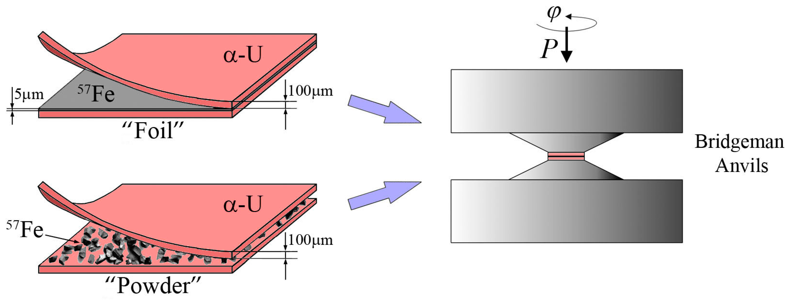
2. Materials and Methods

The samples of α-U based on 238U with a natural iron impurity in amounts of 3 wt.% (the contents of resonance isotope, 57Fe, in natural iron is ~2.1%) were studied. The initial as-received α-U samples were as a foil of 100 μm thickness. Some samples were used as a powder, ground by broaching the file with a following fining in a jasper mortar. It is known that the mutual solubility of uranium and iron is negligible (iron solubility in α-U at 650 °C is less than 0.014%, and uranium solubility in α-Fe is near zero) [14]. Moreover, to obtain the required quality of Mössbauer spectra in the experiment with the mechanical synthesis, the iron was enriched with the resonance (Mössbauer) isotope, 57Fe, up to 96%.
Mechanical synthesis was performed in conditions of severe plastic deformation by high-pressure torsion (HPT) in rotating Bridgman anvils [3,15]. HPT was performed on sandwich-like samples prepared from two α-U plates of 100 μm thickness with the resonance 57Fe between them. In this study, the experiment with two types of initial iron was performed; see Figure 1. The iron powder was represented by particles with a wide size and shape distribution (the mean size was 100 microns). The first case dealt with a 57Fe foil of 5 μm thickness, and was marked as a mechanical synthesis of a “foil” type; moreover, this technique was applied to the samples with a powdered 57Fe iron placed between α-U plates—marked as a “powder” type (Figure 1, “powder” sample). HPT was performed at 8 GPa by ground anvil rotation at the rate of 0.3 rpm up to deformation assessed in the anvil rounds as n = 5 and 10 rounds. After deformation by HPT, the “foil”- and “powder”-type samples revealed a thickness close to 100 μm. To reach the necessary thickness for the Mössbauer thin absorber (10–15 μm), further thinning was performed using a lapping tool and diamond paste (4–7 μm grain). Some samples after thinning were annealed at 300 °C for 1 and 5 h (the latter was provided by additional annealing for 4 h of the sample with the preliminary annealing within 1 h).
The 57Fe Mössbauer spectra of γ-quanta absorption were measured at room temperature (20 °C) and constant acceleration using an MS-1101 spectrometer (Research Institute of Physics SFedU, Rostov–on–Don, Russia) and 57Co(Rh) source. The values of isomer shift are given relative to α-Fe at 20 °C. Due to the complicated shape of the obtained Mössbauer spectra, they were fitted using MS Tools software (Versions 6.1 and 7.2, M.V. Lomonosov Moscow State University, Moscow, Russia) [16]. In particular, the distri product (applied for locally inhomogeneous systems with a multi-component structure and low spectra resolution) was also used. It was of help in increasing the spectra resolution by reconstruction of the p(V) and p(H) distributions, i.e., the probabilities of resonant absorption on the Doppler velocity scale, V, and effective magnetic field, H. Furthermore, the Mössbauer spectra model was specified referring to a type of p(V) and p(H) distribution and apriori data analysis. The values of hyperfine parameters as well as the impact of partial spectra were calculated by the standard procedure of integral spectra-fitting using the Lorentzian line shape in the Spectr program [16]. Quantitative phase analysis was performed by evaluation of the relative integral intensities of Mössbauer spectra components known to be proportional to a number of iron atoms in a particular phase (without accounting for the Debye–Waller factor).
A study of the structure using electron microscopy was performed by transmission electron microscope JEM 200CX (JEOL, Tokyo, Japan) with accelerating voltage of 160 kV. Phase identification was done using the dark-field technique and electron microdiffraction. The steel structure was investigated using a Quanta 200 scanning electron microscope (FEI Company, Hillsboro, OR, USA) with accelerating voltage of ~30 kV. The PEGASUS system was also applied to obtain images in various regimes and perform chemical microanalysis.

3. Experimental Results

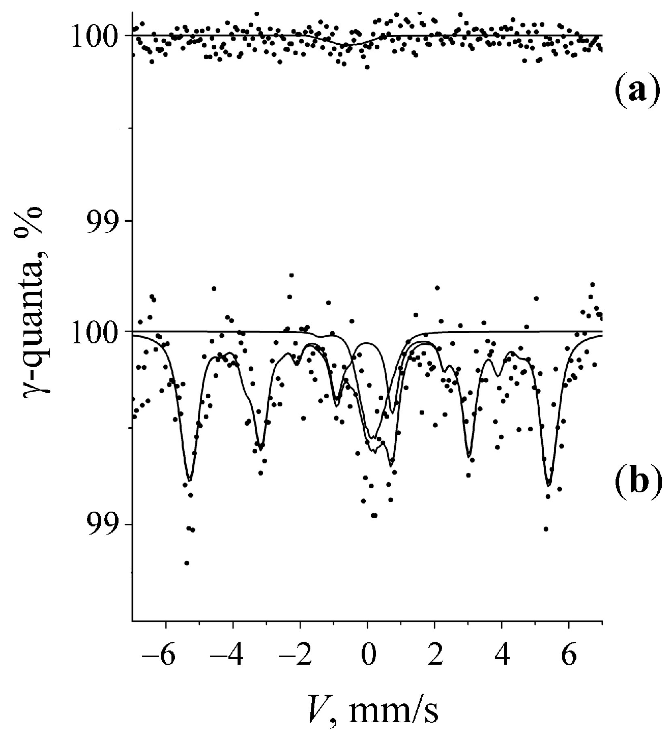
3.1. Mössbauer Spectra of Initial α-U Sample with a Natural Fe Impurity

The Mössbauer spectra measurement of the initial α-U sample with a natural Fe impurity of 3 wt.% prepared as a thin foil of 10–15 μm failed. Negligible resonant absorption was registered within the statistical noise near the zero point of Doppler velocity, Figure 2a. This fact can be explained by the almost total absorption of the 14.4 kEv resonance radiation from the Mössbauer source by the uranium plate.
Powdered alloy samples prepared with additional grinding in the jasper mortar were measured successfully. The Mössbauer spectrum shown in Figure 2b is represented by the superposition of two components, namely, a ferromagnetic sextet with α-Fe parameters (H ~330.4 kOe) and a broadened central line related to a non-magnetic material (up to 20%). Unfortunately, poor spectrum quality did not allow for performing a detailed analysis. However, the central line position at the velocity scale coincides with the location of additional absorption in the “foil”-type sample.

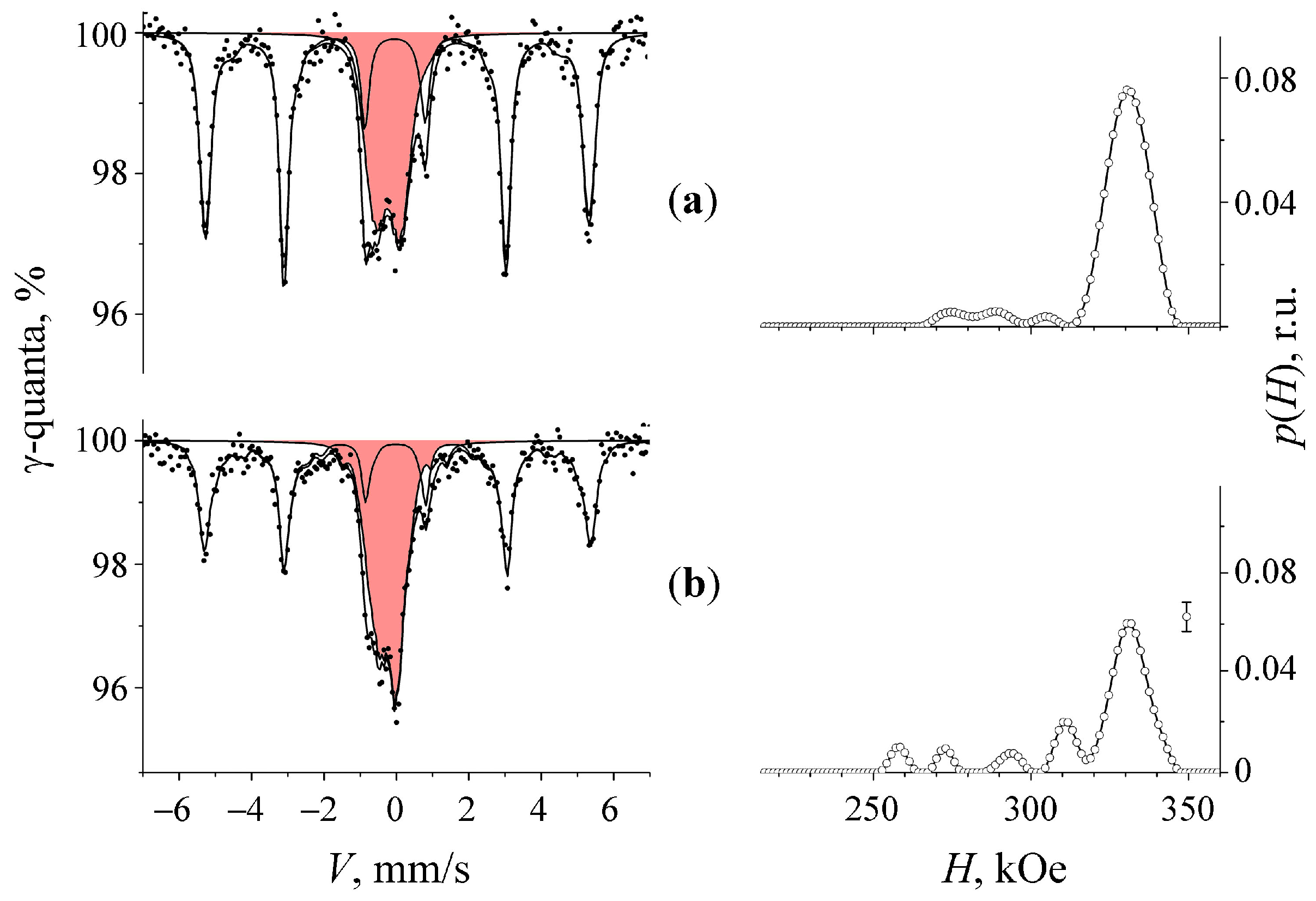
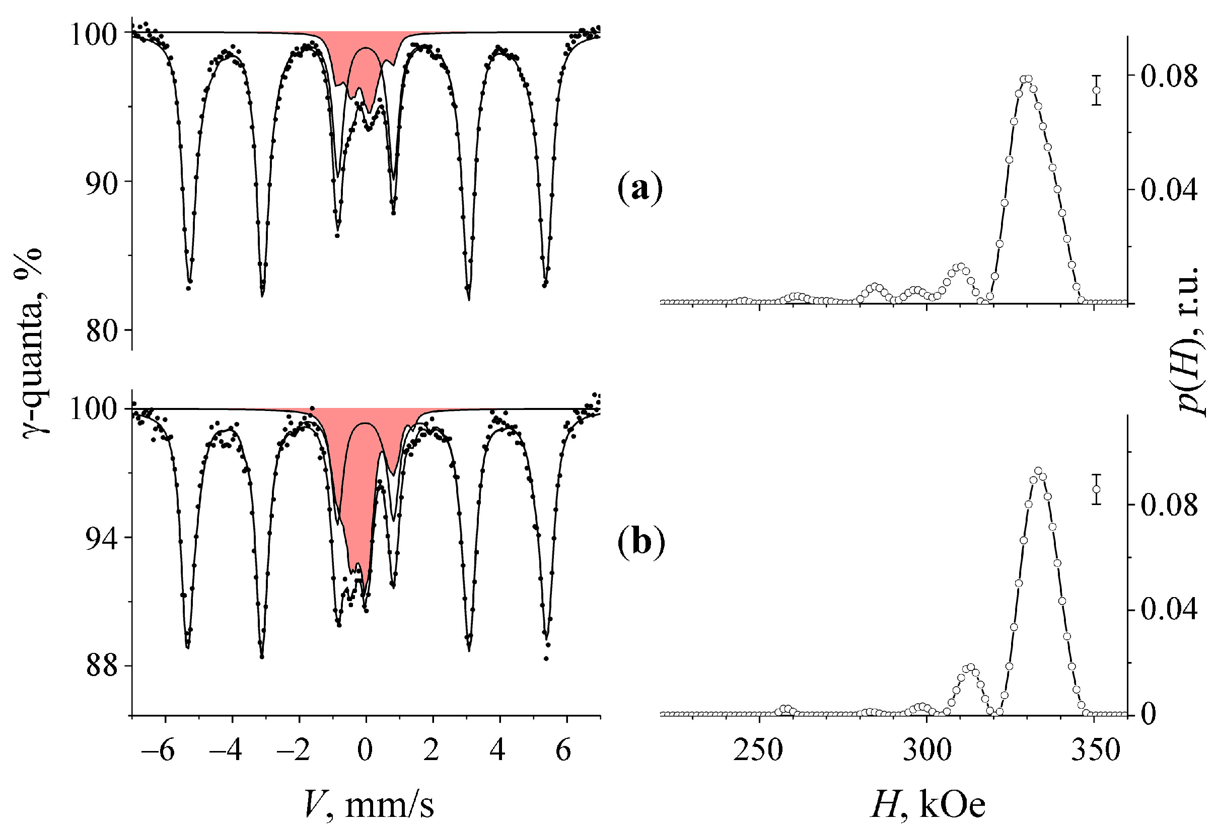
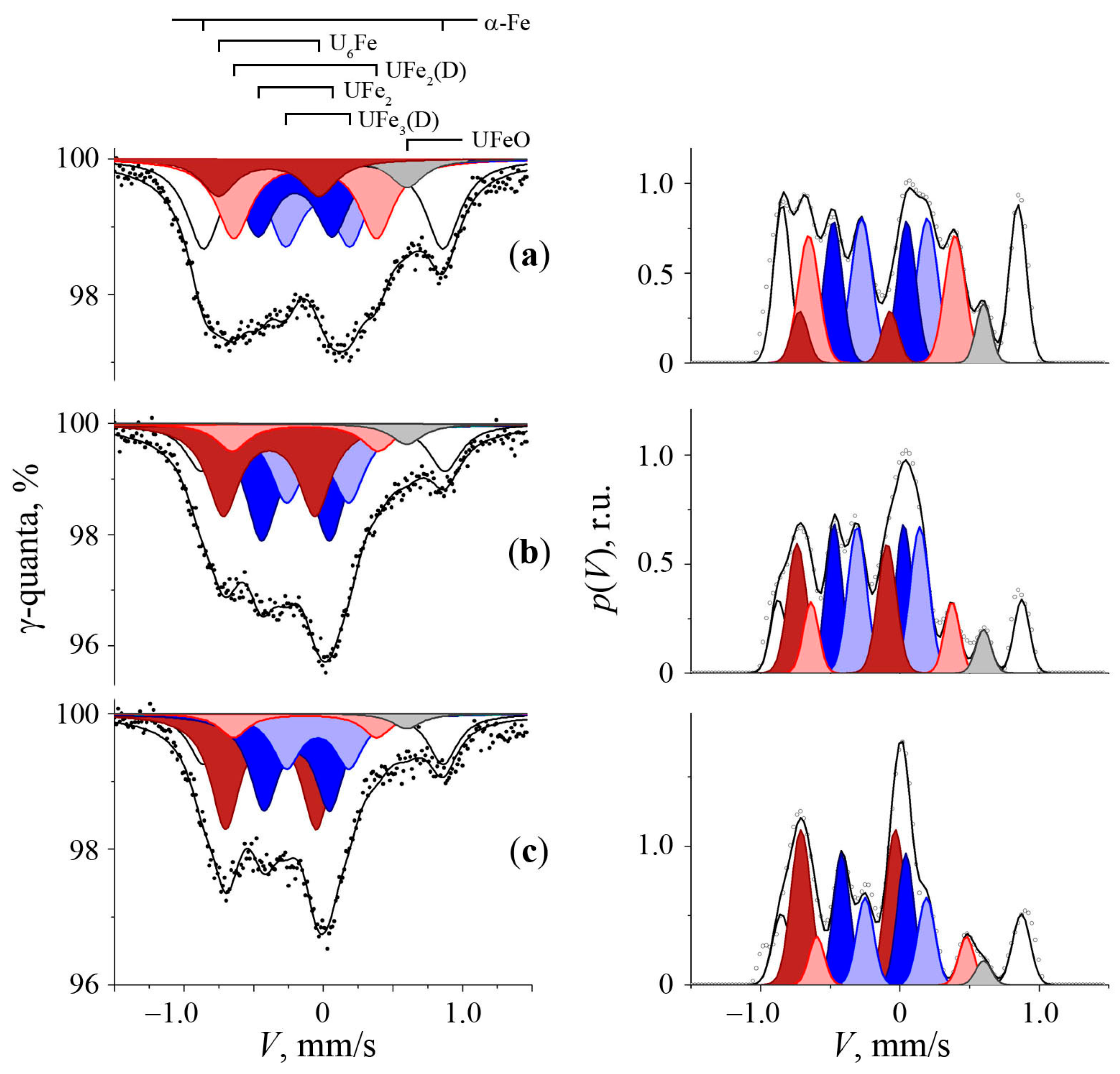
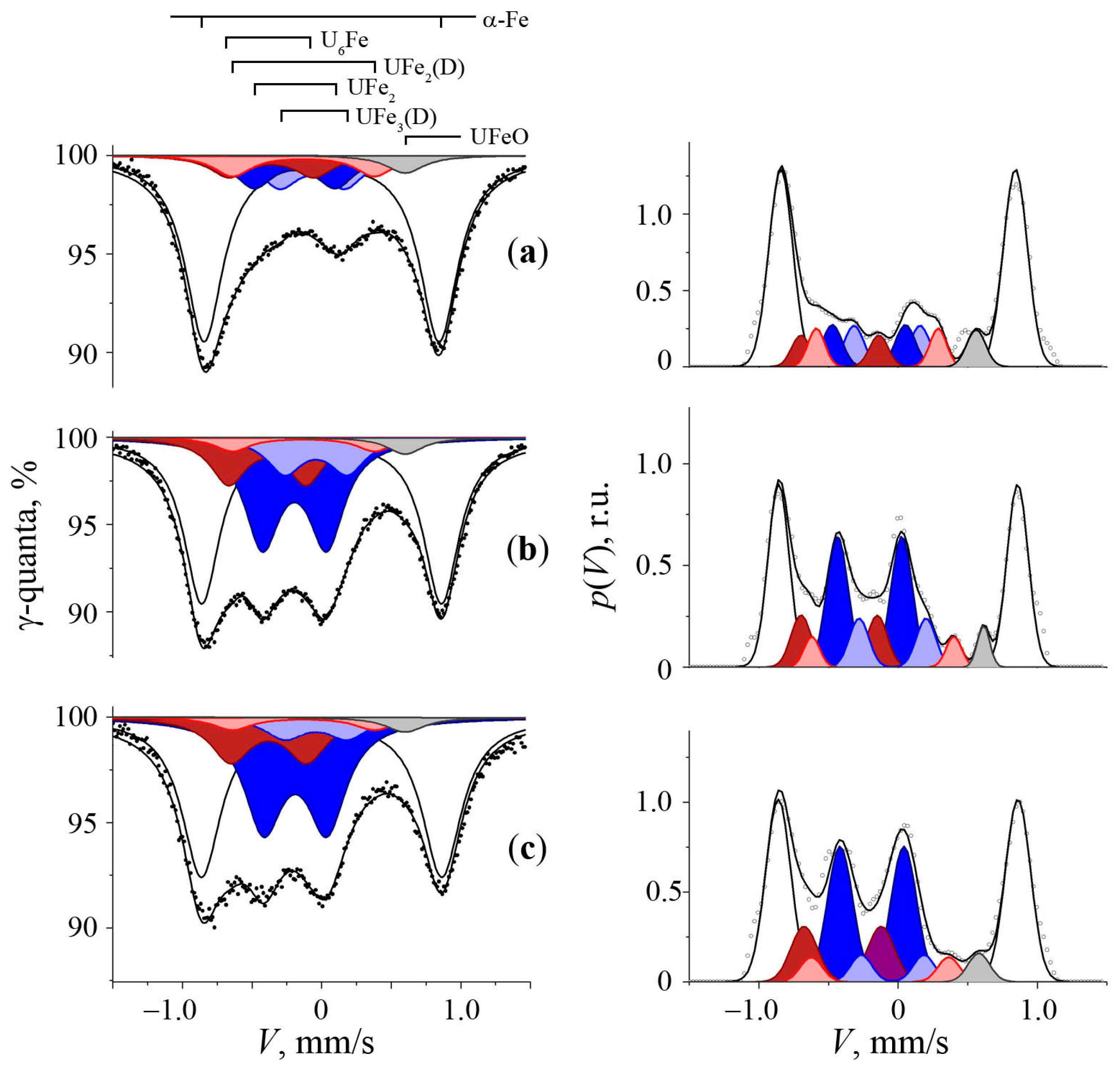
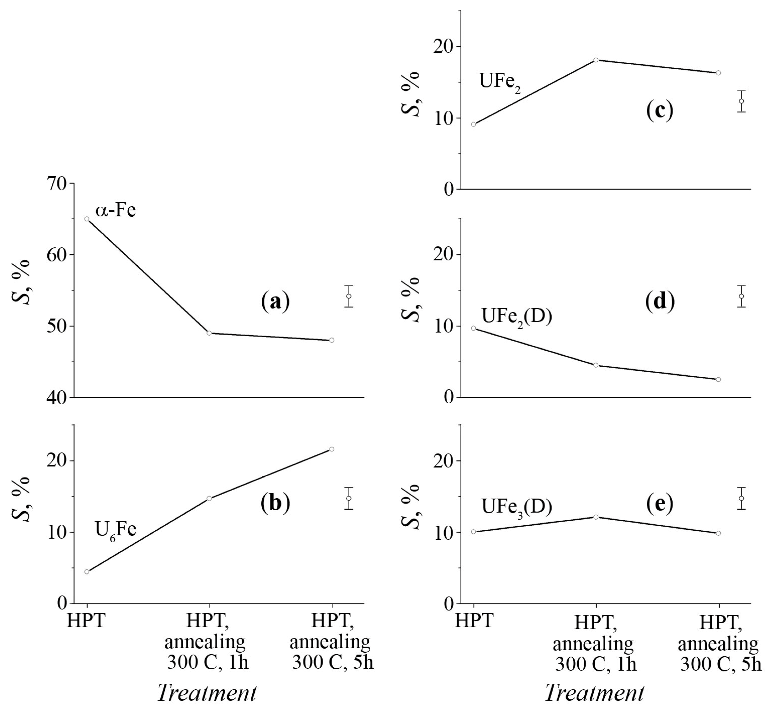
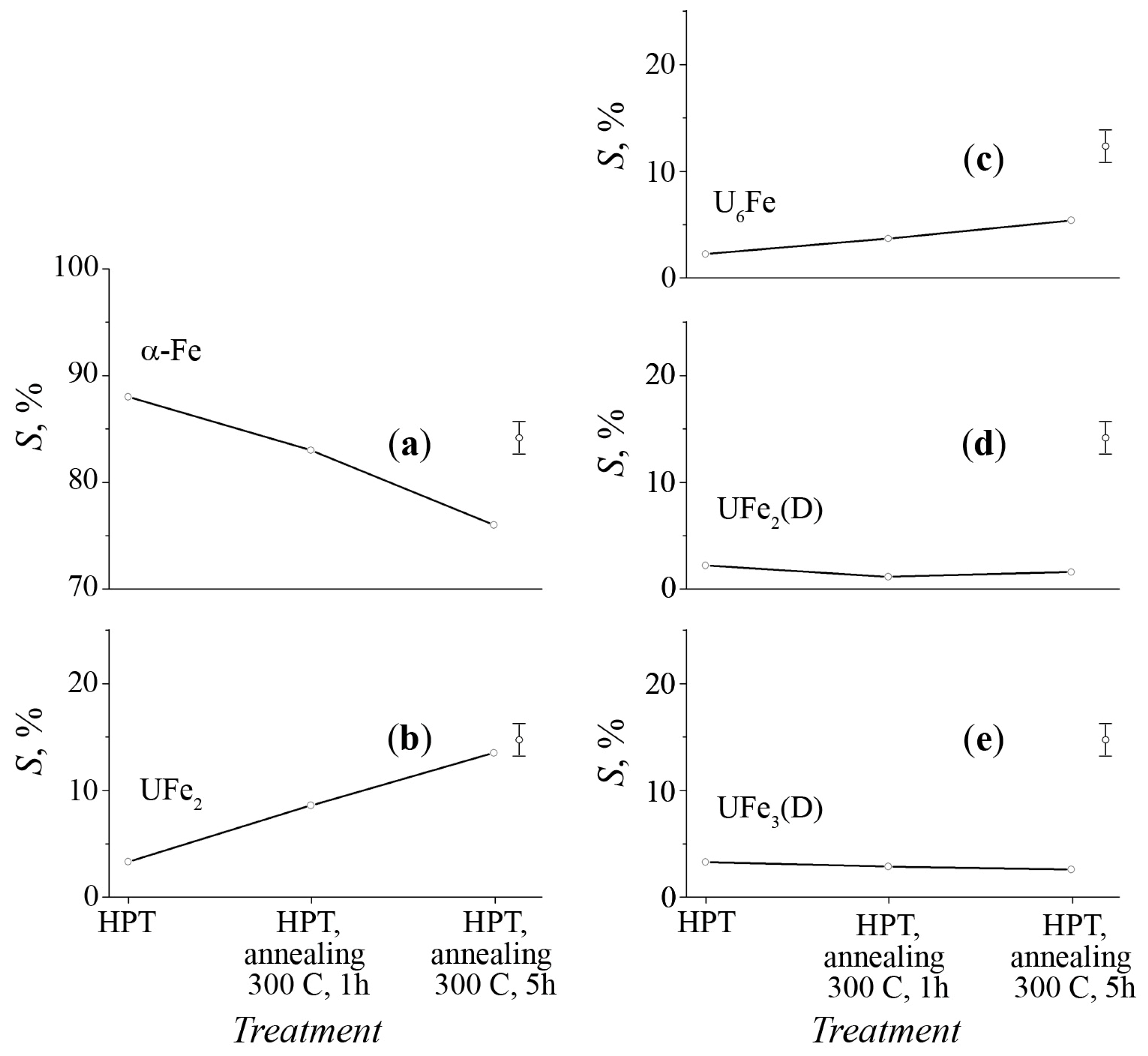
3.2. Mössbauer Spectra of α-U + 57Fe Sample after Mechanical Synthesis

The Mössbauer spectra of the samples (enriched with 57Fe) obtained after HPT as “foil”- and “powder”-type ones were found to be visually similar, Figure 3 and Figure 4. Additionally to the α-Fe sextet, a broadened central line was revealed and marked as UxFey. After HPT, the α-Fe spectrum magnetic texture was changed and evaluated as the ratio of sextet lines intensities as A(1.6):A(2.5):A(3.4) = 3:A(2.5):1 [17]. The value A(2.5) = 4sin2θ/(1 + cos2θ), where θ—is an angle between directions of the inner effective field on the 57Fe nucleus and γ-quanta transmission.
The magnetic texture parameter for the isotropic distribution of magnetic moments is A(2.5) = 2. After applying HPT to the “foil”-type sample, this parameter was A(2.5) = 3, and the “powder”-type sample A(2.5) = 2.8, which indicates the rotation of iron magnetic moments and results from a large tensile stress in the plane of the sample after severe plastic deformation.
The annealing at 300 °C resulted in an increased amount of the central component. In the spectra of the “foil”-type sample, the latter grew from 36% to 51% and, in the “powder”-type sample, from 12% to 24%. In response to annealing, the A(2.5) value drops to 2.5, which reveals a magnetic texture close to the isotropic one, due to the relaxation of mechanical stresses caused by HPT. The spectrum also demonstrated an insignificant sextet of a smaller magnetic field (~314 kOe), which may result from U atoms passed into the α-Fe matrix as a substitutional impurity or residual static distortion of the iron lattice caused by deformation, Figure 3 and Figure 4.
A more thorough analysis of the spectrum’s central region required Mössbauer spectra measurements with higher resolution in the velocity range, from minus –1.2 to 1.2 mm/s, and the application of the distri program [16] to reconstitute the p(V) distribution of resonance absorption lines on the Doppler velocity scale (Figure 5 and Figure 6). The calculation results demonstrated that the central parts of the Mössbauer spectra obtained had similar hyperfine structures in the cases of the mechanically synthesized sample and the ones after annealing. The p(V) distribution fit using a number of lines with Gaussian shape and a priori data for the hyperfine parameters of the intermetallic phases and U and Fe compounds allowed for modeling the spectra central parts, in the case of the mechanically synthesized samples (marked as UxFey), as a superposition of doublets related to the well-known intermetallic compounds, U6Fe, UFe2 and other UFe2(D) and UFe3(D) ones. Moreover, it was revealed that the Mössbauer spectra also contained some doublets related to a small amount of UFeO.
Annealing at 300 °C of both the “foil”- and “powder”-type samples resulted in variation in the components’ contributions without qualitative modification of the spectra structure. Analysis of the Mössbauer spectra of the “foil”- and “powder”-type samples revealed that mechanical synthesis at room temperature takes place as phase development associated with U6Fe, UFe2, UFe2(D) and UFe3(D) doublets, the hyperfine parameters of which are given in Table 1. Doublets associated with U6Fe and UFe2 are characterized by hyperfine parameters, isomer (Is) and quadrupole (Qs) shifts, corresponding to the certain intermetallic structures, namely, U6Fe and UFe2 [18,19,20,21,22,23], developed in accordance with an equilibrium diagram of a U–Fe system [14]. Isomer shift values of UFe2(D) and UFe3(D) doublets were found to be close to those of the UFe2+x and UFe3 phases, obtained by ultrafast cooling of the U–Fe liquid alloy with a variable iron content [23]. Taking into account the dependence of isomer shift values from the intermetallic composition [17,23], new phases, UFe2(D) and UFe3(D), developed in conditions of HPT can be attributed to the intermetallics with increased iron content, that is, peculiar to the structure with increased electronegativity, see Table 1.
The integral intensity of components with Mössbauer parameters associated with U6Fe formed during the mechanical synthesis of the “foil”-type was 3–5%, with following growth up to 15% and 20% following low annealing at 300 °C for 1 and 5 h, respectively, Figure 7. The intensity growth of the doublet related to U6Fe was consistent with the decreasing of α-Fe sextet intensity by the same value; see Figure 7a,b. This fact means that iron after deformation, marked as Fe(D), in a mechanical mixture with strained uranium, marked as U(D), is a precursor of intermetallic phase U6Fe development. The phase transition of the strained mechanical mixture of iron and uranium taking place at room temperature and low heating indicates a strong phase nonequilibrium state of the structure U(D) + Fe(D).
The trend in the integral intensity quantitative variation in doublets UFe2, UFe2(D) and UFe3(D) at low annealing, namely, a 5–7% growth of UFe2 doublet intensity at an equal variation in the total intensity of doublets UFe2(D) and UFe3(D) provides for considering new phases as a precursor to the equilibrium phase of UFe2, Figure 7c–e. The phase transition of imperfect phases during heating probably goes through the ordering of nonstoichiometric UFe2(D) and UFe3(D) phases toward the UFe2 structure. This idea can be confirmed by the close hyperfine parameters (Is and Qs) of the UFe2(D) and UFe2+x structures, obtained in the experiments with ultrafast cooling from melt and considered as a nonstoichiometric Laves phase; see Table 1. Formed in the HPT phase, the UFe3(D) revealed a less substantial decrease in intensity with increased annealing time. The slowing down of the kinetics of transformation of UFe3(D) into the UFe2 structure during annealing is probably associated with the higher iron content and significant deviation from stoichiometry. The mechanically synthesized UFe3(D) structure was described by the doublet with the isomer shift value close to that of UFe3 in the experiments with ultrafast cooling from the melt with similar compositions [23]. The component observed after HPT as the quadrupole doublet UFeO (~2%) had similar hyperfine parameters, with ferrous iron oxide, and had not changed its intensity with annealing. This fact allows supposing iron oxide formed during annealing [22].
The variation in partial contributions from quadrupole doublets in the spectra of “foil”- and “powder”-type samples was found to be different. The annealing of the “powder”-type sample at 300 °C resulted in domination growth of the doublet, UFe2, due to the sextet related to iron; see Figure 8. Other spectra components, namely, the doublets U6Fe, UFe2(D) and UFe3(D), revealed a similar variation direction to that in the case of the “foil”-type sample. However, the quantitative assessments of these variations were proven to be inside the experimental error.
The peculiarities of the ferromagnetic α-Fe sextet in the Mössbauer spectra of the samples, namely, the appearance of a satellite with insignificant intensity and a hyperfine magnetic field of ~314 kOe, may result from a solid solution formation with uranium substitution in a bcc crystal lattice of iron, Figure 3 and Figure 4. The evaluation of impurity content associated with the satellite sextet using a calculation procedure for diluted solid solutions of iron [24,25] was ~3.6%. However, the same appearance and amount of satellite sextet in the iron spectrum after annealing did not support this assumption. The development of the satellite sextet is likely a result of the remaining large number of deformation defects in the iron structure formed under HPT [26] and in the nanocrystalline iron [27].

3.3. The Structure of U–Fe Alloy

The structure of the initial sample, α-U, with an admixture of natural iron is represented by grains with uniform etchability (mostly α-U), with a small amount of iron (about 1–2 wt.%). It is clearly seen that an insignificant amount of iron precipitates as thin layers or chains (Figure 9a,b), as iron solubility in uranium at low temperatures is supposed to be at a minimum. The electron microscopy images (Figure 9c,d) demonstrate thin iron-containing lamellar precipitates formed in the grain body of uranium. In accordance with the equilibrium diagram for U–Fe [14], this structure may be a eutectoid (α-U + U6Fe).
The structure of the mechanically synthesized alloy of α-U with 57Fe in a “foil” type after HPT at 10 rounds and following annealing at 300 °C for 5 h is shown in Figure 10. It should be emphasized that the fineness degree of the sample microstructure is nonuniform. Electron microscopy of the synthesized sample allowed for identifying the following three types of particles with different morphology.
-
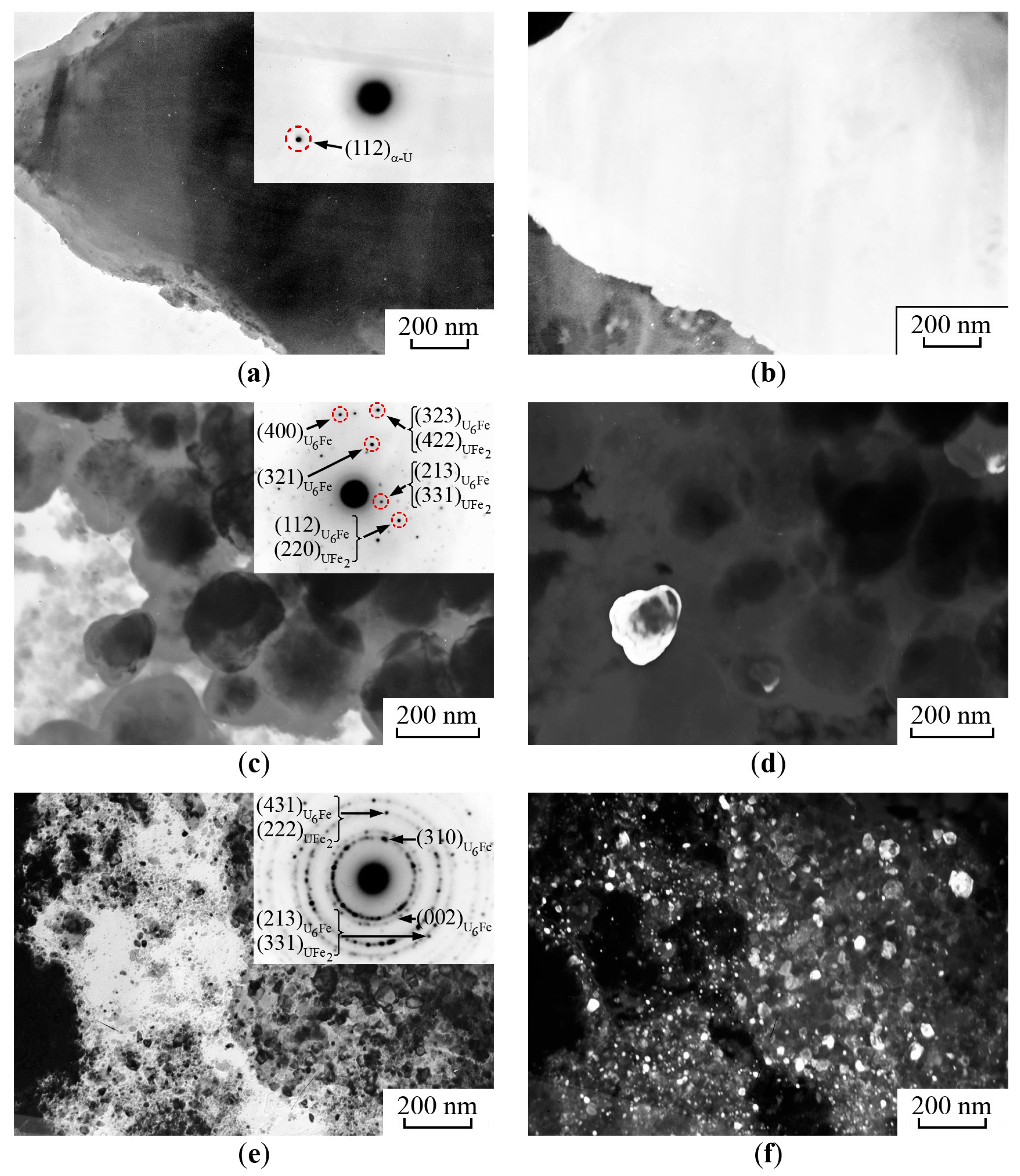
The first type. There are coarse particles with irregular forms (Figure 10a,b) in the structure of the synthesized sample of α-U with 57Fe. The size of these particles reaches several microns. Microdiffraction of this region revealed individual reflections with an interplanar distance corresponding to α-U [28] (Figure 10a).
-
The second type is represented by rounded particles with a size of 100–200 nm (Figure 10c,d). The microdiffraction pattern of these particles revealed many irregular reflections (Figure 10c). The interpretation of the microdiffraction data showed that interplanar distances from individual reflections could correspond to those of the U6Fe and UFe2 phases [28]. The dark-field image (Figure 10d) was obtained in the reflection associated with the UFe6 and U2Fe phases.
-
The third type. The regions with nanocrystalline structures were also observed in the mechanically synthesized alloy of α-U with 57Fe, Figure 10e,f. The peculiar electron diffraction pattern contained ring reflections from heavy disordered crystallites of the α-U, U6Fe and UFe2 phases. The size of intermetallic particles in these regions was 10–50 nm.

4. Discussion

Thus, application of HPT at room temperature in both “foil”-type and “powder”-type experiments revealed that the mechanical synthesis of uranium and iron passed through the formation of equilibrium intermetallic UFe2 and U6Fe phases and precursors in the form of metastable defective UFe2(D) and UFe3(D) phases, as well as the mechanical mixture of strained uranium U(D) and iron Fe(D) being not in a solid solution condition. At low annealing, nonstoichiometric metastable phases, UFe2(D) and UFe3(D), were converted into stoichiometric intermetallic UFe2 and resulted in a dispersed mixture of uranium and iron, U(D) and Fe(D), forming intermetallic U6Fe. The general scheme of phase transitions in the mixture of uranium and iron in a “foil”-type sample under HPT can be represented by the following:
U + Fe HPT U ( D ) + Fe ( D ) + U 6 Fe UFe 2 ( D ) + UFe 3 ( D ) + UFe 2 Anneal U 6 Fe UFe 2
The spectrum of the sample synthesized as the “powder” type revealed a different doublet partial contribution variation after HPT and annealing. After HPT, the doublet related to UFe2 became the basic component in the central part of the spectrum, and UFe2 is the doublet that demonstrated variations during further annealing:
U + Fe HPT U ( D ) + Fe ( D ) + UFe 2 Anneal UFe 2
Other spectral components, namely U6Fe, UFe2(D) and UFe3(D), were observed to vary in a similar way as in the case of the “foil”-type sample but at a smaller value. The revealed variations in mechanical synthesis after HPT and annealing can be explained by different conditions of plastic deformation for the components of the iron and uranium mixture in the samples prepared as the “foil” and “powder” types. A crucial condition for atomic mass transfer induced by deformation is a plastic component of the latter. The iron particle size in the “powder”-type sample is relatively large and allows for conducting an initial stage of deformation due to the larger ductile particles from the iron component. In the case of sample deformation prepared by the “foil”-type, the thin, 5-micron iron plate doesn’t play the role of the main component of the plastic flow. Instead, the uranium plate takes part in the deformation process. Moreover, the changing of the phase transition channel for the “powder”-type samples with the dominant formation of intermetallic UFe2 can be associated with a higher ratio of the iron component in the interphase region of mixing phases. Thus, the kinetics of the phase transition in the “powder”-type sample is achieved from the iron side with the dominant formation of UFe2 intermetallics, while in the “foil”-type sample, the phase transition goes from the uranium side with the development of mainly U6Fe intermetallics. It is possible to conclude that the deformation with further annealing of mechanically synthesized “foil”- and “powder”-type samples results in the same set of phases. The observed morphological variation in the structure obtained by mechanical synthesis of a U–Fe system (Figure 10) can be explained, in particular, by the deformation heterogeneity in terms of rate and velocity, which is peculiar to the HPT technique [3,15].
Similar diffusion processes of the formation of intermediate stoichiometric phases and nonstoichiometric defective ones were observed during the HPT-induced mechanical synthesis of aluminum and iron powders [29]. In particular, it was established that the cold work HPT of iron, aluminum and aluminides, Al6Fe, in the aluminum matrix resulted in the development of stoichiometric phases and defective nonstoichiometric ones by subtraction type: Al6Fe → Al6–xFe → Al9Fe2 → Al9–xFe2. Phases Al6–xFe and Al9Fe2 were also observed during ultrafast cooling [29]. The defective structure underwent reverse transition during the following low annealing due to the ordering: Al6–xFe → Al6Fe, Al9–xFe2 → Al9Fe2. The data obtained in [29], as well as in [30,31] regarding the implantation of iron into aluminum and studies on rapid quenching and cold working of diluted alloys [32,33,34], confirm common features of a vacancy transformation mechanism under the ultrafast cooling and plastic cold work. As was shown above for the uranium and iron mixture, the defective phases UFe2(D) and UFe3(D) formed under the HPT-revealed Mössbauer parameters, similar to those of the phases obtained by ultrafast cooling of the U–Fe liquid alloy of close composition. The obtained results may confirm the common vacancy mechanism of phase transitions during mechanical synthesis under the severe plastic deformation and ultrafast cooling of U–Fe liquid alloys. It should be noted that according to data from [35], saturation by vacancy complexes of an alloy structure under HPT leads to a concentration in the region of pre-melting temperatures. The electron microscopy data obtained in the current study demonstrated the development of strongly dispersed intermetallic structures after the cold work and low annealing, Figure 10e,f. This fact, together with the Mössbauer data, confirms a conception of mechanical diffusion decay of the structure formed during the mechanical synthesis.
The development of ordered intermetallic compounds at room temperature in conditions of a mechanical synthesis of uranium and iron atoms points out the high degree of non-equilibrium structure. It was already illustrated in [3,4,5,6] that mechanical energy dissipation in metallic systems may occur by an anomalous route of dynamic recrystallization, aging and diffusion phase transitions. In particular, it was established that in conditions of severe plastic deformation, the mechanical synthesis takes place via the competition of nonequilibrium phase merging, atomic mixing and diffusion processes, with a further formation of new thermodynamically reasonable intermediate structures and phases. In these conditions, the direction and kinetics of structural phase transitions induced by deformation are specified by saturation with non-fixed point defects and thermodynamic impetus towards new phase development [3,7,36].
According to the Hume-Rothery rules, there is a thermodynamic stimulus of intermetallic compound formation for a U–Fe system within a whole region of compositions and a wide region of temperatures [37]. This fact can be clearly seen via an equilibrium diagram where uranium and iron form U6Fe + U eutectic and Laves phases with variable composition in the temperature range lower than 725 °C [14]. An enhanced influence of thermodynamic potential on the processes of short-range and long-range ordering, intermetallics and interstitial phase formation [3,7] was demonstrated in the experiments on mega plastic deformation on more heat-resistant alloys than those of aluminum using Bridgeman anvils and ball mills and in comparison with results of high-energy particle irradiation [2,3]. Similar results concerning the influence of the thermodynamic potential (chemical affinity) of atoms in transition metal nitrides on the direction and kinetics of mechanical synthesis were demonstrated in the deformation dissolution of nitrides in iron alloys [7]. Moreover, it was established that during the mechanically induced formation of substitutional and interstitial alloys, a homologous temperature of reversal direction from disordering to ordering was strongly dependent on the structure saturation by mobile point defects and thermodynamic phase stability potential [3,4,5,36,37]. According to the equilibrium diagram of U–Fe, the addition of iron into uranium is accompanied by a significant liquidus temperature decrease that results from the low intersolubility of uranium and iron and appears as increased atom mobility under HPT conditions at relatively low temperatures. Thus, one can conclude that a low temperature during mechanical synthesis, along with the intermediate phases’ formation, could be a criterion of the binding forces of the atoms in the phases and the structural stability, as well as the melting and sublimation temperatures and formation heat [5].
The results obtained within the current study demonstrate the stability of UFe2 and U6Fe intermetallics under severe plastic deformation and correspond to data about the high thermal stability of uranium structures alloyed with iron [13]. Dynamic decay processes in conditions of alloy structure saturation with a large number of point defects were also revealed for a cascade of atomic displacements in conditions of neutron irradiation. Taking into account the general patterns of severe plastic deformation and fast neutron irradiation influence, the effect of the former can be used for the prediction of deformation and radiation stability in a wide temperature range for intermetallics.

5. Conclusions

Structural phase transformations in the U–Fe system in the conditions of mechanical synthesis of metallic α-U and 57Fe under severe plastic deformation in Bridgman anvils with further annealing at 300 °C were studied using Mössbauer spectroscopy, transmission and scanning electron microscopy. It was shown that the mechanical synthesis resulting from high-pressure torsion was accomplished by the formation of U6Fe and UFe2 intermetallic compounds and defective phases, namely, UFe2(D) and UFe3(D), whose Mössbauer parameters were close to those of phases obtained in conditions of ultrafast cooling from U and Fe melting. Further isothermal annealing of samples was accompanied by a dominant development of intermetallics, U6Fe, in the “foil”-type sample synthesized with high-pressure torsion and UFe2 in the “powder”-type sample. The mechanical synthesis of uranium and iron observed in conditions of severe plastic deformation occurs at room temperature through dynamic aging without solid solution development. Dynamic aging at room temperature results from the low intersolubility of uranium and iron, development of mobile point defects and high thermodynamic stimulus of U6Fe and UFe2 intermetallic formation. The deformation and thermal stability of U6Fe and UFe2 intermetallics were analyzed in relation to the results of U–Fe alloy decomposition in conditions of ultrafast cooling.

Author Contributions

Conceptualization, V.S. (Valery Shabashov) and K.K.; methodology, V.S. (Valery Shabashov), V.P., K.K. and A.Z.; validation, V.S. (Valery Shabashov), K.K. and V.S. (Victor Sagaradze); formal analysis, V.S. (Valery Shabashov), K.K., A.Z. and N.K.; investigation, K.K. and N.K.; visualization, K.K., A.Z. and N.K.; writing—original draft preparation, V.S. (Valery Shabashov); writing—review and editing, V.S. (Valery Shabashov), K.K. and V.S. (Victor Sagaradze); project administration, V.S. (Valery Shabashov). All authors have read and agreed to the published version of the manuscript.

Funding

The research was carried out within the state assignment of the Ministry of Science and Higher Education of the Russian Federation (theme “Structure” No. 122021000033-2).

Data Availability Statement

Data is contained within the article. The data presented in this study are available in “Deformation–Induced Mechanical Synthesis of U and Fe”.

Acknowledgments

The Mössbauer and electron microscopic studies were performed in the Mössbauer Spectroscopy and the Electron Microscopy Departments of the Collective Usage Center at the M.N. Mikheev Institute of Metal Physics, Ural Division, Russian Academy of Sciences. The authors express their thanks to Yurii Zuev for the helpful discussions.

Conflicts of Interest

The authors declare no conflict of interest.

References

  1. Nelson, R.S.; Hudson, J.A.; Mazey, D.J. The stability of precipitates in an irradiation environment. J. Nucl. Mater. 1972, 44, 318–330. [Google Scholar] [CrossRef]
  2. Sagaradze, V.V.; Shabashov, V.A.; Litvinov, A.V.; Koloskov, V.M.; Parkhomenko, V.D. Radiation-induced dissolution of ni3m intermetallic particles (M = Ti, Al, Zr) in displacement cascades in Fe-Ni-M alloys irradiated by neutrons at 340 K. Phys. Met. Metall. 2010, 109, 475–482. [Google Scholar] [CrossRef]
  3. Shabashov, V.; Sagaradze, V.; Kozlov, K.; Ustyugov, Y. Atomic order and submicrostructure in iron alloys at megaplastic deformation. Metals 2018, 8, 995. [Google Scholar] [CrossRef]
  4. Glezer, A.M.; Metlov, L.S. Physics of megaplastic (severe) deformation in solids. Phys. Sol. State 2010, 52, 1162–1169. [Google Scholar] [CrossRef]
  5. Shabashov, V.; Lyashkov, K.; Kozlov, K.; Zavalishin, A.; Zamatovskii, A.; Kataeva, N.; Sagaradze, V.; Ustyugov, Y. Critical redistribution of nitrogen in the austenitic Cr–Mn steel under severe plastic deformation. Materials 2021, 14, 7116. [Google Scholar] [CrossRef] [PubMed]
  6. Li, J.G.; Umemoto, M.; Todaka, Y.; Fujisaku, K.; Tsuchiya, K. The dynamic phase transformation and formation of nanocrystalline structure in SUS304 austenitic stainless steel subjected to high pressure torsion. Rev. Adv. Mater. Sci. 2008, 18, 577–582. [Google Scholar]
  7. Shabashov, V.; Lyashkov, K.; Zamatovskii, A.; Kozlov, K.; Kataeva, N.; Novikov, E.; Ustyugov, Y. Mechanosynthesis of high-nitrogen steels strengthened by secondary titanium nitrides. Materials 2022, 15, 5038. [Google Scholar] [CrossRef]
  8. Tagawa, H. Phase relations and thermodynamic properties of the uranium-nitrogen system. J. Nucl. Mater. 1974, 51, 78–89. [Google Scholar] [CrossRef]
  9. Fink, J.K. Thermophysical properties of uranium dioxide. J. Nucl. Mater. 2000, 279, 1–18. [Google Scholar] [CrossRef]
  10. Kittel, J.H.; Ayer, J.E.; Beck, W.N.; Brodsky, M.B.; O’Boyle, D.R.; Zegler, S.T.; Ellinger, F.H.; Miner, W.N.; Schonfeld, F.W.; Nelson, R.D. Plutonium and plutonium alloys as nuclear fuel materials. Nucl. Eng. Des. 1971, 15, 373–440. [Google Scholar] [CrossRef]
  11. Ogata, T. Metal Fuel. Compr. Nucl. Mater. 2012, 3, 1–40. [Google Scholar] [CrossRef]
  12. Sandratskii, L.M.; Silkin, V.M.; Havela, L. Entangled origins of the nonmagnetic states of U and Fe atoms in hydrogenated UFeGe. Phys. Rev. Materials 2023, 7, 024414. [Google Scholar] [CrossRef]
  13. Geiger, T.; Fizzotti, C. Studien an Uran-Eisen-Legierungen. Schweizer Arch. Angew. Wiss. Technol. 1958, 24, 27–32. [Google Scholar]
  14. Okamoto, H. Phase Diagrams of Binary Iron Alloys; ASM International, The Material Information Society: Geauga County, OH, USA, 1993. [Google Scholar]
  15. Levitas, V.I.; Zarechnyy, O.M. Numerical study of stress and plastic strain evolution under compression and shear of a sample in a rotational anvil cell. High Press Res. 2010, 30, 653–669. [Google Scholar] [CrossRef]
  16. Rusakov, V.S.; Kadyrzhanov, K.K. Mössbauer spectroscopy of locally inhomogeneous systems. Hyperfine Interact. 2005, 164, 87–97. [Google Scholar] [CrossRef]
  17. Frauenfelder, H.; Nagle, D.E.; Taylor, R.D.; Cochran, D.R.F.; Visscher, W.M. Elliptical polarization of Fe57 gamma rays. Phys. Rev. 1962, 126, 1065–1075. [Google Scholar] [CrossRef]
  18. Lemon, G.; Boolchand, P.; Stevens, M.; Marcuso, M.; DeLong, L.E.; Huber, J.G. 57Fe Mossbauer spectroscopy of U6Fe. J. Less Common Metals 1987, 127, 329–334. [Google Scholar] [CrossRef]
  19. Blow, S. A Mössbauer effect study of the metallic compounds U6Fe and Pu6Fe, and the relevance of the results to theories of the behaviour of actinide metals. J. Phys. Chem. Sol. 1969, 30, 1549–1559. [Google Scholar] [CrossRef]
  20. McGuire, T.K.; Herber, R.H. 57Fe Mössbauer effect evidence for magnetostriction in UFe2. Solid State Commun. 1983, 48, 393–395. [Google Scholar] [CrossRef]
  21. Tsutsui, S.; Nakada, M.; Kobayashi, Y.; Nasu, S.; Haga, Y.; Ōnuki, Y. 238U and 57Fe Mössbauer Spectroscopic Study of UFe2. Hyperfine Interact. 2001, 133, 17–21. [Google Scholar] [CrossRef]
  22. Paolasini, L.; Lander, G.H.; Shapiro, S.M.; Caciuffo, R.; Lebech, B.; Regnault, L.-P.; Roessli, B.; Fournier, J.-M. Magnetic excitations in the itinerant ferromagnet UFe2. Phys. Rev. B 1996, 54, 7222–7232. [Google Scholar] [CrossRef] [PubMed]
  23. Havela, L.; Miliyanchuk, K.; Gonçalves, A.P.; Waerenborgh, J.C.; Pereira, L.C.J.; Gaczynski, P.; Lopes, E.B.; Pešička, J. Increase of TC in UFe2+x synthesized by ultrafast cooling. Intermetallics 2011, 19, 113–120. [Google Scholar] [CrossRef]
  24. Vincze, I.; Campbell, I.A. Mossbauer measurements in iron based alloys with transition metals. J. Phys. F Met. Phys. 1973, 3, 647–663. [Google Scholar] [CrossRef]
  25. Van der Woude, F.; Sawatzky, G.A. Mossbauer effect in iron and dilute iron based alloys. Phys. Rep. 1974, 12, 335–374. [Google Scholar] [CrossRef]
  26. Shabashov, V.A.; Ovchinnikov, V.V.; Mulyukov, R.R.; Valiev, R.Z.; Filippova, N.P. Deformation-induced nonequilibrium grain-boundary phase in submicrocrystalline iron. Nanostruct. Mater. 1999, 11, 1017–1029. [Google Scholar] [CrossRef]
  27. Birringer, R.; Gleiter, H. Nanocrystalline Materials. In Encyclopaedia of Materials Science and Engineering; Suppl. 1; Pergamon Press: Oxford, UK, 1988. [Google Scholar]
  28. Output Generated by SingleCrystal(TM) for Windows 2.3.2 Copyright © 2023–2015 CrystalMaker Software Ltd. Available online: http://www.crystalmaker.com (accessed on 10 August 2023).
  29. Shabashov, V.A.; Brodova, I.G.; Mukoseev, A.G.; Sagaradze, V.V.; Litvinov, A.V. Deformation-induced phase transformations in the Al–Fe system under intensive plastic deformation. J. Phys. Condens. Matter. 2007, 19, 386222. [Google Scholar] [CrossRef]
  30. Preston, R.S.; Gerlach, R. Mössbauer effect in dilute alloys of iron in aluminum. Phys. Rev. B 1971, 3, 1519–1526. [Google Scholar] [CrossRef]
  31. Preston, R.S.; Nasu, S.; Gonser, U. Association of defects with iron impurities in FCC aluminium. J. Phys. Colloques 1979, 40, C2-564–C2-565. [Google Scholar] [CrossRef]
  32. Sassa, K.; Goto, H.; Ishida, Y.; Kato, M. Mössbauer analysis of 57Co associated with quenched-in lattice defects in aluminium. Scr. Metall. 1977, 11, 1029–1032. [Google Scholar] [CrossRef]
  33. Sassa, K.; Ishida, Y.; Kaneko, K. Mössbauer spectroscopy of 57Fe implanted to aluminium at liquid nitrogen temperature. J. Phys. Colloques 1979, 40, C2-556–C2-558. [Google Scholar] [CrossRef]
  34. Young, R.M.K.; Clyne, T.W. An Al–Fe intermetallic phase formed during controlled solidification. Scr. Metall. 1981, 15, 1211–1216. [Google Scholar] [CrossRef]
  35. Gubicza, J.; Dobatkin, S.V.; Khosravi, E. Reduction of vacancy concentration during storage of severely deformed Cu. Mater. Sci. Eng. A 2010, 527, 6102–6104. [Google Scholar] [CrossRef]
  36. Shabashov, V.A.; Kozlov, K.; Ustyugov, Y.; Zamatovskii, A.; Tolmachev, T.; Novikov, E. Mössbauer Analysis of Deformation–Induced Acceleration of Short-Range Concentration Separation in Fe-Cr Alloys—Effect of the Substitution Impurity: Sb and Au. Metals 2020, 10, 725. [Google Scholar] [CrossRef]
  37. Hume-Rothery, W. Elements of Structural Metallurgy. In Monograph and Report; Series No. 26; Institute of Metals: London, UK, 1961. [Google Scholar]
Figure 1. The scheme of mechanical synthesis of α-U with 57Fe using the high-pressure torsion technique in rotating Bridgeman anvils as the “foil” type and “powder” type.
Metals 14 00055 g001
Figure 2. Mössbauer spectra of initial sample of α-U alloy with admixture of natural iron in an amount of 3 wt.%. (a)—foil, (b)—ground powder with additional fining.
Metals 14 00055 g002
Figure 3. Mössbauer spectra of the samples obtained by mechanical synthesis of α-U with 57Fe in a “foil” type after: (a)—high-pressure torsion with n = 10 r.; (b)—annealing at 300 °C for 5 h.
Metals 14 00055 g003
Figure 4. Mössbauer spectra of the samples obtained by mechanical synthesis of α-U with 57Fe in a “powder” type after: (a)—high-pressure torsion with n = 5 r.; (b)—annealing at 300 °C for 5 h.
Metals 14 00055 g004
Figure 5. The central parts of the Mössbauer spectra and corresponding distribution functions p(V), with the decomposition of the samples obtained by mechanical synthesis of α-U with 57Fe in a “foil” type. Treatment: (a)—high-pressure torsion with n = 10 r.; (b)—high-pressure torsion with further annealing at 300 °C, 1 h; (c)—high-pressure torsion with further annealing at 300 °C, 5 h.
Metals 14 00055 g005
Figure 6. The central parts of the Mössbauer spectra and corresponding distribution functions, p(V), with the decomposition of the samples obtained by mechanical synthesis of α-U with 57Fe in a “powder” type. Treatment: (a)—high-pressure torsion with n = 5 r.; (b)—high-pressure torsion with further annealing at 300 °C, 1 h; (c)—high-pressure torsion with further annealing at 300 °C, 5 h.
Metals 14 00055 g006
Figure 7. Variation in integral intensities, S, of Mössbauer spectra components of the samples of α-U with 57Fe obtained by mechanical synthesis using high-pressure torsion with n = 10 r. in a “foil” type and indicated treatment. Components: (a)—α-Fe; (b)—U6Fe; (c)—UFe2; (d)—UFe2(D); (e)—UFe3(D).
Metals 14 00055 g007
Figure 8. Variation in integral intensities, S, of Mössbauer spectra components for the samples of α-U with 57Fe obtained by mechanical synthesis using high-pressure torsion, with n = 5 r. in a “powder” type and indicated treatment. Components: (a)—α-Fe; (b)—Ufe2; (c)—U6Fe; (d)—UFe2(D); (e)—UFe3(D).
Metals 14 00055 g008
Figure 9. The structure of α-U with an admixture of natural iron. (a,b)—scanning electron microscopy images and elemental analysis data; (c,d)—bright-field images of the lamellar precipitates of the secondary phase.
Metals 14 00055 g009
Figure 10. The microstructure of the mechanically synthesized alloy, α-U and 57Fe, obtained by high-pressure torsion in rotating Bridgeman anvils in a “foil” type, n = 10 r., with a following annealing at 300 °C for 5 h. (a,b)—the particles of the first type; (c,d)—the particles of the second type; (e,f)—the particles of the third type. (a,c,e)—bright-field images and corresponding microdiffraction patterns; (b)—dark-field images of region (a), obtained in the reflection (112)α-U; (d)—dark-field image of regions (c), obtained in the reflections (213)U6Fe + (331)UFe2; (f)—dark-field image of region (e), obtained in the reflections (431)U6Fe + (222)UFe2.
Metals 14 00055 g010
Table 1. Hyperfine parameters (isomer shift, IS, and quadrupole splitting, QS) and relative integral intensity, S, of components in the central part of the Mössbauer spectra of mechanically synthesized samples of α-U with 57Fe (by high-pressure torsion in rotating Bridgeman anvils as “foil”-type and “powder”-type samples) and data from [18,23].
PhaseIS, mm/s
±0.01
QS, mm/s
±0.02
S, % (Foil)
±2.0
S, % (Powder)
±2.0
Reference
U6Fe−0.370.694.52.2Current
work
UFe2−0.190.489.13.3
UFe2(D)−0.131.029.72.2
UFe3(D)−0.040.4610.03.3
UFeO0.90.833.01.0
U6Fe−0.370.69[18]
UFe2−0.190.46[23]
UFe2.3−0.140.94[23]
UFe3−0.041.15[23]
Disclaimer/Publisher’s Note: The statements, opinions and data contained in all publications are solely those of the individual author(s) and contributor(s) and not of MDPI and/or the editor(s). MDPI and/or the editor(s) disclaim responsibility for any injury to people or property resulting from any ideas, methods, instructions or products referred to in the content.

