1. Introduction
Tungsten Inert Gas (TIG) welding is a versatile and precise welding method that uses a non-consumable tungsten electrode to create an electric arc and melt the base metals, while a separate filler metal can also be added if needed. Dissimilar welding is commonly used in various industries, including aerospace, automotive, and construction, where different metals with distinct properties need to be joined for specific applications. When performing dissimilar TIG welding, it is crucial to consider the differences among various parameters, such as melting points, thermal conductivity, and expansion coefficients, between the metallic materials being joined. Proper selection of welding parameters, as well as careful preparation of the joint, is essential to ensuring a strong, durable, and defect-free weld [
1,
2,
3].
Inconel 718 (IN718) is a high-strength, corrosion-resistant nickel-based superalloy. It is primarily composed of nickel, along with significant amounts of chromium, iron, niobium, molybdenum, and other alloying elements. These elements contribute to its exceptional mechanical properties, high-temperature stability, and resistance to oxidation and corrosion. It is widely used in a variety of demanding applications, particularly in aerospace, including aircraft and spacecraft engine components (turbine blades and discs, combustion chambers, rocket motor cases), and in industrial processes (gas turbine engines, nuclear reactors, etc.), where high-temperature and corrosive environments are encountered. One of the most notable features of IN718 is its ability to maintain its strength and structural integrity at elevated temperatures. It can withstand temperatures ranging from cryogenic levels to about 1300 °C [
4,
5].
On the other hand, low-carbon AISI 304L (SS304L) is a popular and widely used stainless steel alloy, especially in welding applications, in order to minimize carbide precipitation. It is an austenitic stainless steel composed of primarily iron, chromium (18–20% Cr), and nickel (8–10.5%). It is part of the 300 series of stainless steels, known for their excellent corrosion resistance and versatility in various applications, such as chemical or nuclear reactors, heat exchangers, pressure vessels, aviation industries, etc. The addition of chromium significantly improves corrosion resistance and also acts as a ferrite stabilizer (“α” or “δ” ferrite). The high nickel content provides an austenitic crystal structure at a low temperature. Furthermore, the low carbon percentage narrows the development of carbides at high temperatures [
6,
7].
Although Inconel and stainless steels are highly corrosion-resistant metals, IN718 is preferred when improved mechanical properties at high temperatures are required [
8,
9]. The main reason for the development of its high strength is the formation of gamma prime (
γ′-Ni
3(Al,Ti)) and gamma double prime (
γ″-Ni
3Nb) phases during the precipitation hardening process. Also, the combined effect of chromium and cobalt in the nickel solid solution matrix provides a comparatively improved oxidation resistance [
10,
11]. As IN718 presents good weldability, in conjunction with its mechanical characteristics at high temperatures, it is preferred in applications requiring high-temperature mechanical properties. Nevertheless, careful consideration of various welding parameters is needed to ensure a high-quality weld with minimal risk of cracking or other defects. The specific parameters may vary depending on the welding process used, but direct current electrode-negative (DCEN) is often preferred for TIG welding. The wide use of that welding technique is attributed mainly to low investment and operating costs [
12,
13]. The above features make TIG welding attractive for producing high-quality metallurgical joints between Ni-based superalloy and stainless steel.
However, the so far published literature has given little attention to the evaluation of IN718 and SS304L dissimilar TIG joints. Adomako et al. studied the microstructure evolution and mechanical properties of dissimilar joints between IN718 and SS304 by laser beam welding [
13]. According to their results, a crack-free deep penetrating joint was obtained, while the weld metal was primarily composed of the austenite phase with a distribution of Laves and Ti/Nb carbides in the interdendritic regions. No significant grain coarsening or negative metallurgical effects were observed at the heat-affected zones (HAZ). The fusion zone (FZ) recorded lower hardness than the base metal, mainly due to the depletion of strengthening elements (Nb, Mo, and Ti) and a lack of hardening
γ″ particles. Similar results were obtained by Pasupuleti et al., who also investigated the dissimilar laser-welded joints between IN718 and SS304L for automobile applications. The weld parameters studied were shown to have a significant impact on the fabricated joint’s microstructural and mechanical characteristics, which in turn determined the joint’s overall quality [
14]. Kumar et al. also studied the dissimilar autogenous laser beam welding between IN718 and SS304L [
15]. Similarly, the microstructural study indicated the presence of the Laves phase in the weld zone. Additionally, the weld zone showed heterogeneous microstructural formation, owing to the non-uniform welding heat in the different areas of the weld zone. Regarding the mechanical properties, the tensile specimens showed a brittle failure at the SS304L side, which was initiated from the weld top, with an average tensile stress of about 660 MPa. Sunder et al. investigated the mechanical properties and the microstructure of dissimilar welded joints fabricated by metal inert gas (MIG) welding between IN718 and SS304 [
16]. The welded joint showed a good tensile strength and hardness combination. Its ultimate tensile strength was 14% higher and 13% lower than the SS304-SS304 and IN718-IN718 joints, respectively. The hardness of the dissimilar joints was comparable to the SS304-SS304 plate but remarkably lower than the IN718-IN718 joint. Finally, Sihori et al. studied the microstructure and mechanical properties of combined GTAW and SMAW dissimilar welded joints between IN718 and SS304L [
17]. According to their results, the weld metal consisted of a fully austenitic microstructure with Nb/Ti-rich carbide phases along the inter-dendritic spaces. The tensile tests showed a failure from the weld metal, which was attributed to alloying element segregation along the interdendritic spaces.
During the welding process, significant microstructural changes occur due to high temperatures and rapid cooling. These changes impact the mechanical properties and overall integrity of the weld. As the molten pool cools, it begins to solidify, and dendritic structures are developed as the alloy atoms arrange themselves into the crystal lattice. These dendrites grow inward from the solidification front and are also observed in the HAZ. The HAZ experiences various microstructural changes, including the dissolution and precipitation of particular phases [
18,
19]. Precipitation of carbides and intermetallic phases can occur, which may affect the HAZ properties. IN718 is known for its
γ′ and
γ″ phases, which can coarsen and potentially change in composition when experiencing high temperatures.
One of the main drawbacks during welding is the potential development of Nb-rich Laves phases ((Ni, Cr, Fe)
2(Nb, Mo, Ti)) in the FZ, which results in the reduction of the joints’ mechanical characteristics, especially that of fracture toughness [
20,
21]. Those types of brittle intermetallic compounds are generated during the solidification of nickel alloys that contain niobium [
3]. The solidification starts with the formation of primary dendrites, which, upon forming, repel niobium, molybdenum, titanium, and carbon, thus leading to the formation of thermodynamically stable phases such as NbC, TiN, and Laves phases in the interdendritic regions. The eutectic reaction of the development of
γ matrix and NbC from the melt leads to the C decrement from the Ni solid solution. As the cooling process proceeds, another eutectic type reaction (liquid→
γ + Laves) can evolve at 1250 °C, after which the solidification process is completed [
10]. Those Laves phases do not present plasticity and can lead to rapid crack initiation and propagation. Furthermore, their formation depletes niobium from the nickel matrix, thus hindering
γ″ phase precipitation.
The dissolution of the developed Laves phases in the nickel solid solution matrix is difficult due to the slow rate of niobium atom diffusivity. However, it can be carried out at relatively high temperatures (higher than 1150 °C) for an extended period [
22,
23]. Nevertheless, performing this type of heat treatment is not feasible for welds since it may result in grain size increases and the initiation of oxidation phenomena. It should also be mentioned that the heat treatment selection process depends on both Laves microstructural characteristics and niobium concentration. In the case of coarser precipitates with higher niobium concentrations, higher temperatures are required during the annealing process for complete dissolution in the nickel dendritic matrix. On the contrary, finer particles of those Nb-rich intermetallic compounds prevent niobium partitioning, thus resulting in the minimization of Laves phase evolution during melting itself [
24,
25].
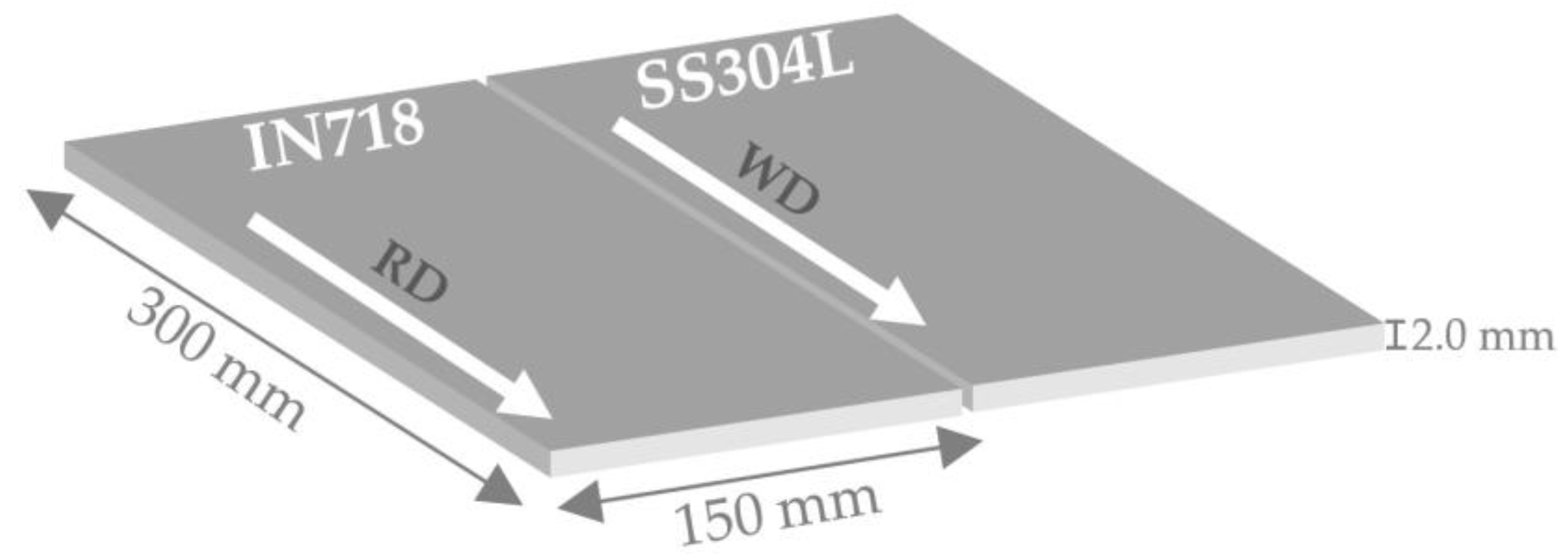
Selecting optimum parameters during TIG welding is beneficial in controlling both segregation phenomena and Laves phase development, thus improving the weld joints’ performance. This includes employing relatively lower weld heat inputs, fast cooling rates, and sharp temperature gradients. Although both IN718 and SS304L present good weldability, their dissimilar welding processes are essential in high-temperature applications as well as in various components like propeller blades, propulsion motors, carriages in the oil industry, and underwater applications [
17,
26]. However, IN718 and SS304L present different thermal expansion coefficients and melting points, properties that may lead to cracking and distortion during joining. TIG, together with electron beam or laser welding, are among the preferred methods for welding these dissimilar materials. Especially TIG allows for precise control over the heat input, reducing the risk of cracking and distortion. The current research work aims to study the effect of welding current variation on the microstructure and hardness profile of TIG-welded IN718 and SS304L via optical and electron microscopy characterization as well as Vickers microhardness measurements of welded samples, respectively.
3. Results and Discussion
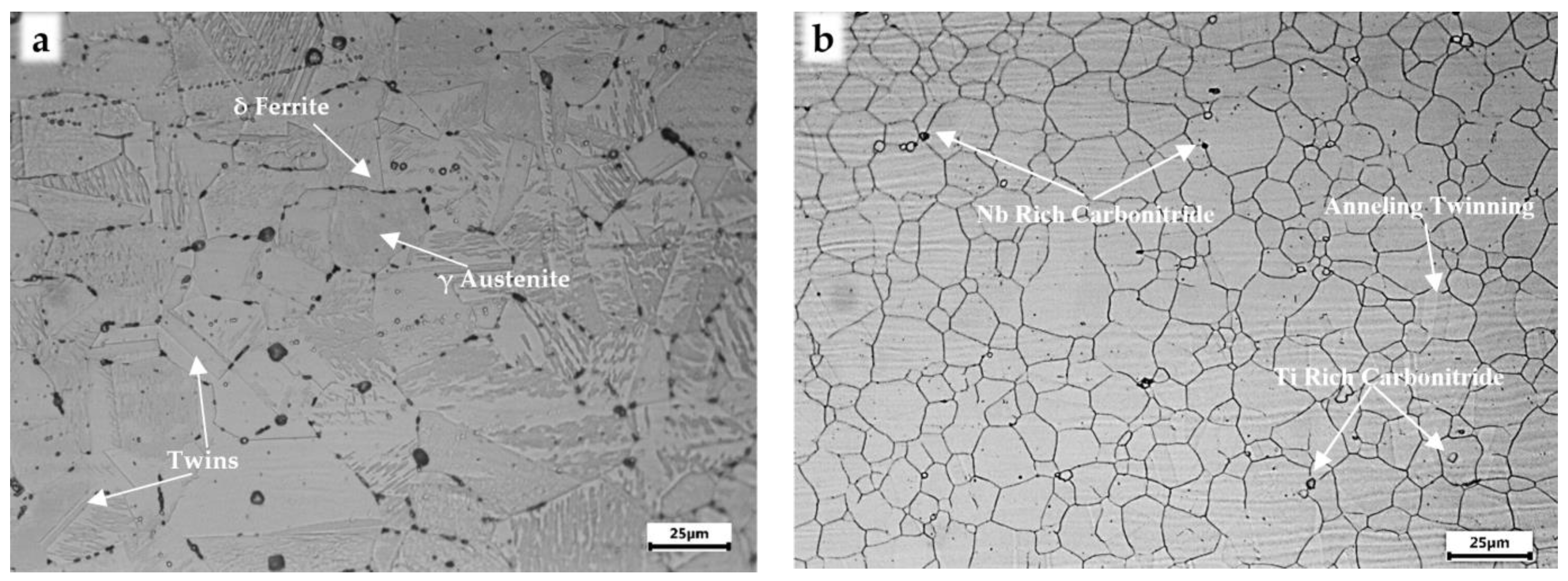
As-received IN718 and SS304L base metals’ optical micrographs are depicted in
Figure 2. IN718 presented a fully recrystallized microstructure with uniformly equiaxed austenite grains. Titanium and niobium-rich secondary carbides/carbonitrides were also observed, mainly at the austenite grain boundaries. On the other hand, the microstructure of AISI 304L mainly consisted of austenite grains, with a relatively inhomogeneous grain size distribution in the range of 25–100 μm and a relatively low fraction of twin boundaries. Also,
δ-ferrite was present at the grain boundaries with the form stringers.
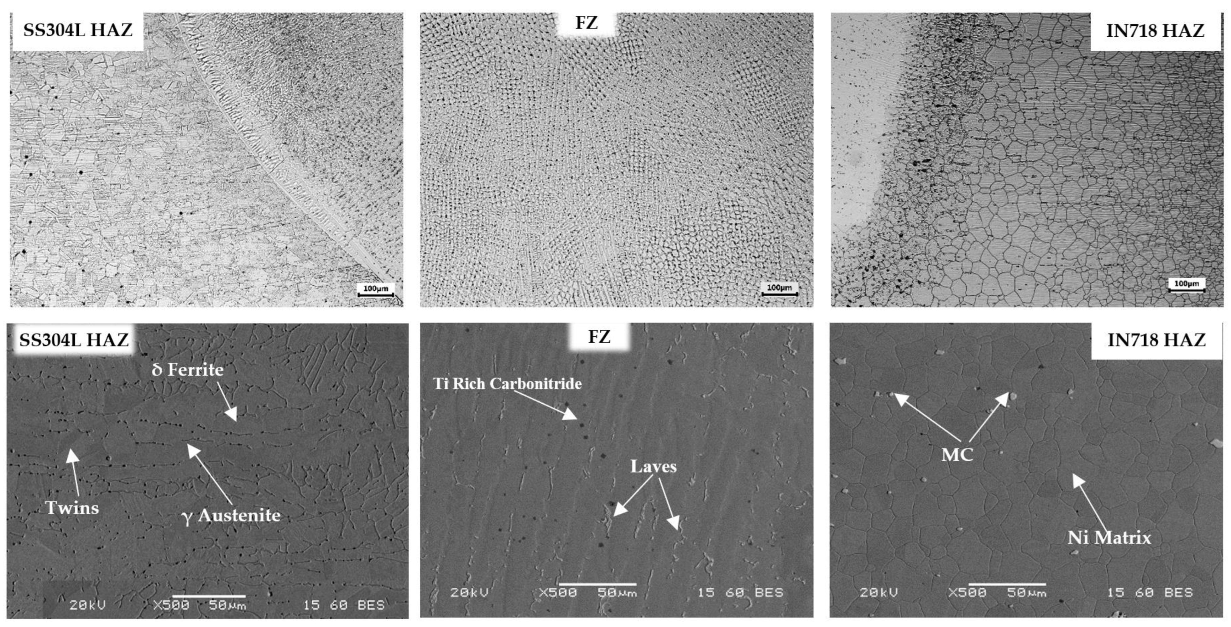
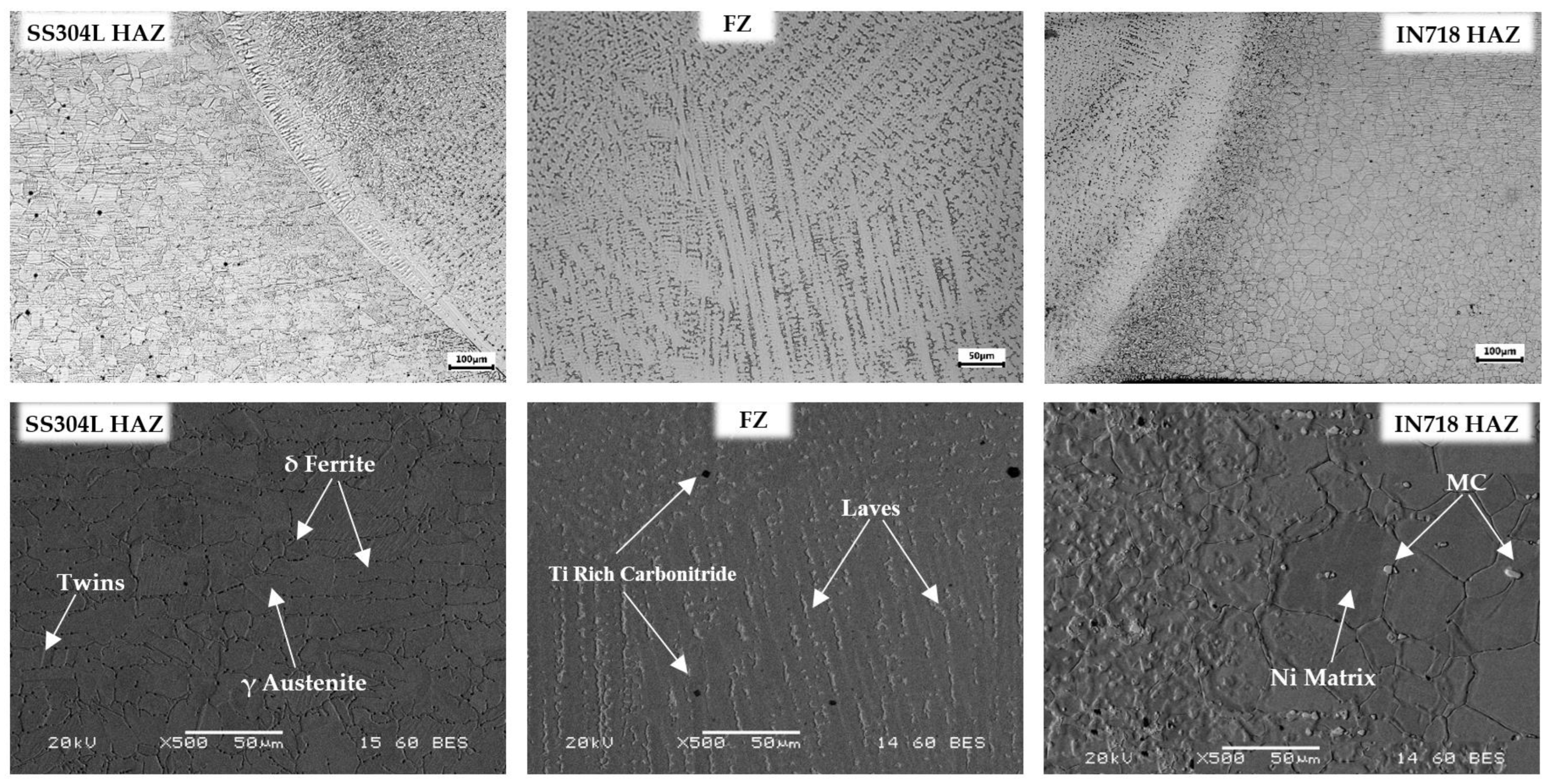
Typical micrographs of the IN718 and SS304L dissimilar TIG joints, at different welding currents, were obtained through an optical and scanning electron microscope in polished sections, focusing on displaying the microstructural feature development in both FZ and HAΖ zones (
Figure 3,
Figure 4 and
Figure 5). The observed surfaces were free of solidification, liquation cracks, and porosity. The maximum width of HAZ was detected near the surface, whereas it decreased in relation to the weld depth as the heat input to the weld surface decreased along the weld depth. Most precipitates were observed at the fusion boundary of IN718 and FZ.
During the temperature increment, the nickel-based superalloy is partially melted and interacts with the weld fusion zone, leading to interdiffusion phenomena and the development of various precipitates. Blocky MC carbides and carbonitrides, highly enriched in Nb and Ti, were identified mainly in IN718 HAZ, especially at grain boundaries, with the form of discrete single crystals, a morphology that corresponds to primary MC carbides developed during the last stages of IN718 solidification.
Near the FZ, the initial grain boundary phases were not fully dissolved into the austenitic matrix during temperature increase, leading to a low melting point eutectic and melting of the grain boundary region. Also, the higher weld heat input provided for the unmixing of the precipitates and led to the formation of coarser grains in the HAZ. The SS304L HAZ microstructure consists of austenitic grains and δ-ferrite, which have been developed in the form of a skeletal network (vermicular).
The formation of the FZ microstructure depends on the solid phase transformations at a high welding heat input and solidification behavior, which are mainly driven by the cooling rate and the composition of the materials to be welded. Delta ferrite is typically generated through austenite transformation at elevated temperatures, which is influenced not only by the alloying elements present in steel but also by the heat input and the consequent cooling rate. Higher heat inputs resulted in slower cooling rates, thus promoting the formation of delta ferrite around austenitic grains.
During cooling and solidification of the molten metal, shrinking may occur, which can lead to solidification cracking (hot weld cracking). Although the existence of δ-ferrite may slightly affect the mechanical or corrosion-resistance properties, in its absence, the potential hot weld microcracks can spread throughout the entire matrix. During crack initiation, propagation is blocked by δ-ferrite, mainly because of its BCC (body-centered cubic) structure.
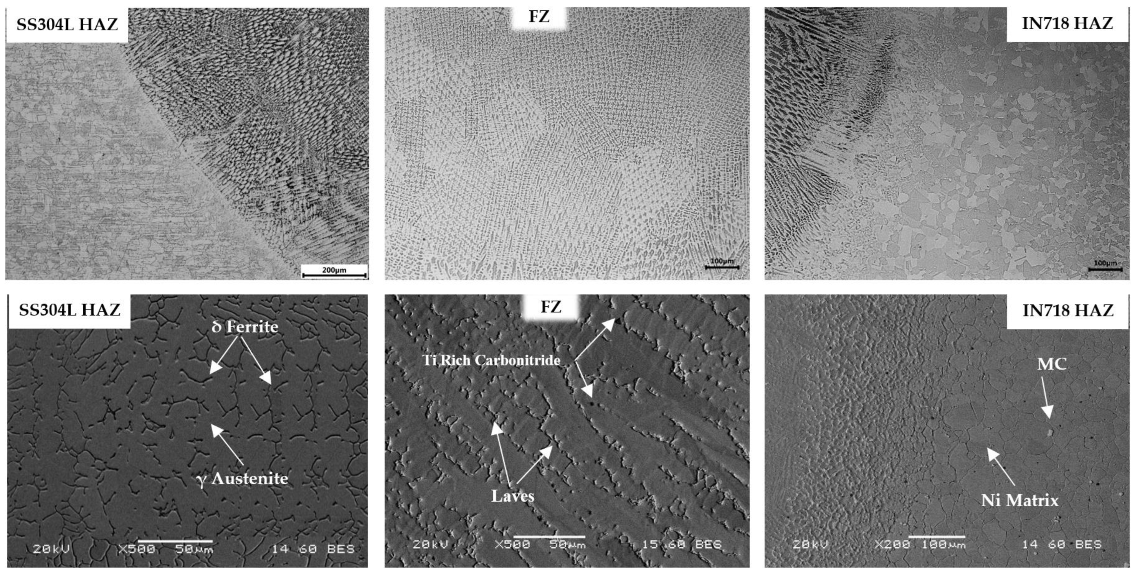
The FZ microstructure morphology of the TIG-welded IN718 and SS304L verified the absence of porosity or other metallurgical defects in the fusion zone. Fine-grained mixed dendritic microstructures were detected throughout the weld zone. The joints fabricated with 70 A and 90 A presented the lowest and highest heat input, respectively, which significantly affected the grain size.
Higher heat input led to a consequent increment in the size of austenitic grains due to a slower cooling rate. The increase in arc linear energy led to an increased size of elongated dendritic groups, and the microstructure mainly consisted of thinner columnar zones oriented in the direction of the fusion line.
The corresponding micrographs showed that elongated columnar dendritic development prevailed in the case of higher welding current. In contrast, decreasing the heat input, in conjunction with the high level of constitutional supercooling during solidification in the TIG welding process, led to the prevalence of equiaxed dendrites, especially in the weld center.
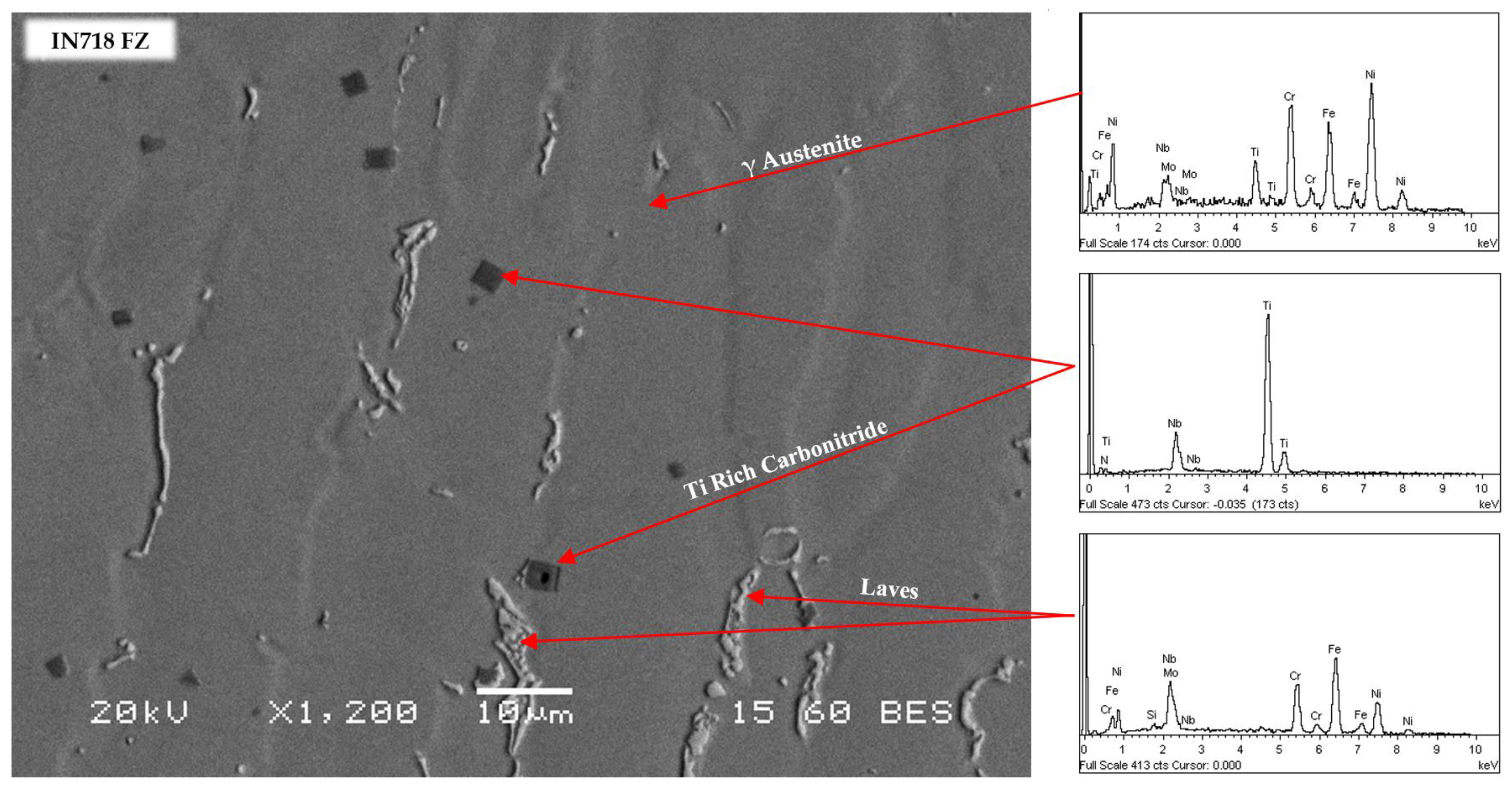
The corresponding microanalyses in the weld joints revealed not only the elemental composition in the austenitic matrix, both in HAZ (
Figure 6) and FZ (
Figure 7), but also the nature of the developed precipitates. In the HAZ, the region surrounding the weld, the material experienced a high-temperature cycle but did not undergo melting. The thermal cycles in this zone influenced the precipitation and dissolution of niobium/titanium carbides in the interdendritic spaces. Higher heat inputs resulted in prolonged exposure to high temperatures in the HAZ, thus leading to the precipitate coarsening. Niobium/titanium carbides have been developed through precipitation from the solid solution during cooling.
At higher temperatures and longer times in the HAZ, the diffusion and precipitation phenomena contributed to the growth of carbides. The coarsening of carbides further led to the migration and diffusion of the alloying elements from the austenitic matrix, thus preventing the formation of γ′ and γ″ secondary precipitates. Similarly, in the FZ, where melting and solidification occur during welding, the behavior of niobium and titanium carbides was also influenced by the heat input and the consequent cooling rates, factors that affected both the final size and distribution of carbides. Faster cooling (lower heat input) led to the dispersion of finer precipitates, contributing to the strengthening of the FZ.
Except for carbides and carbonitrides, the elemental composition also revealed the presence of hard and brittle Laves phases ((FeNiCr)2(NbMoTiSi)), which were dispersed in the interdendritic spaces in the form of elongated islands, characterized by a network-like structure within the microstructure of the material. The formation of the Laves phase involves complex metallurgical reactions during solidification and subsequent cooling. Its formation was influenced by the IN718 initial composition, particularly the Nb and Ti concentrations, which promoted its precipitation and stability. During the solidification of the welded alloy, various phases started to nucleate and grow.
In the molten pool, Nb and/or Mo atoms diffused in the molten metal and combined with Fe atoms to form the first intergranular Laves phase nucleus particles. The cooling rate influenced the microstructure of the solidified material. The diffusion of niobium and titanium at specific locations within the microstructure contributed to its nucleation and growth, whereas the temperature and time at which the alloy was held during solidification and subsequent cooling also influenced its formation and distribution. The heat input, which is directly related to the cooling rate of the FZ, significantly impacted the microstructural evolution and the formation of the Laves phase. According to the results, slower cooling rates, associated with higher heat inputs, provided more time for the diffusion of alloying elements and the formation of the Laves phase at the grain boundaries with a continuous band-like distribution. Its size and density gradually decreased with lower current densities. Decreasing the heat input (and subsequently increasing the cooling rate) resulted in reduced niobium segregation, leading not only to a morphology refinement of the Laves phase but also to its percentage decline in the FZ.
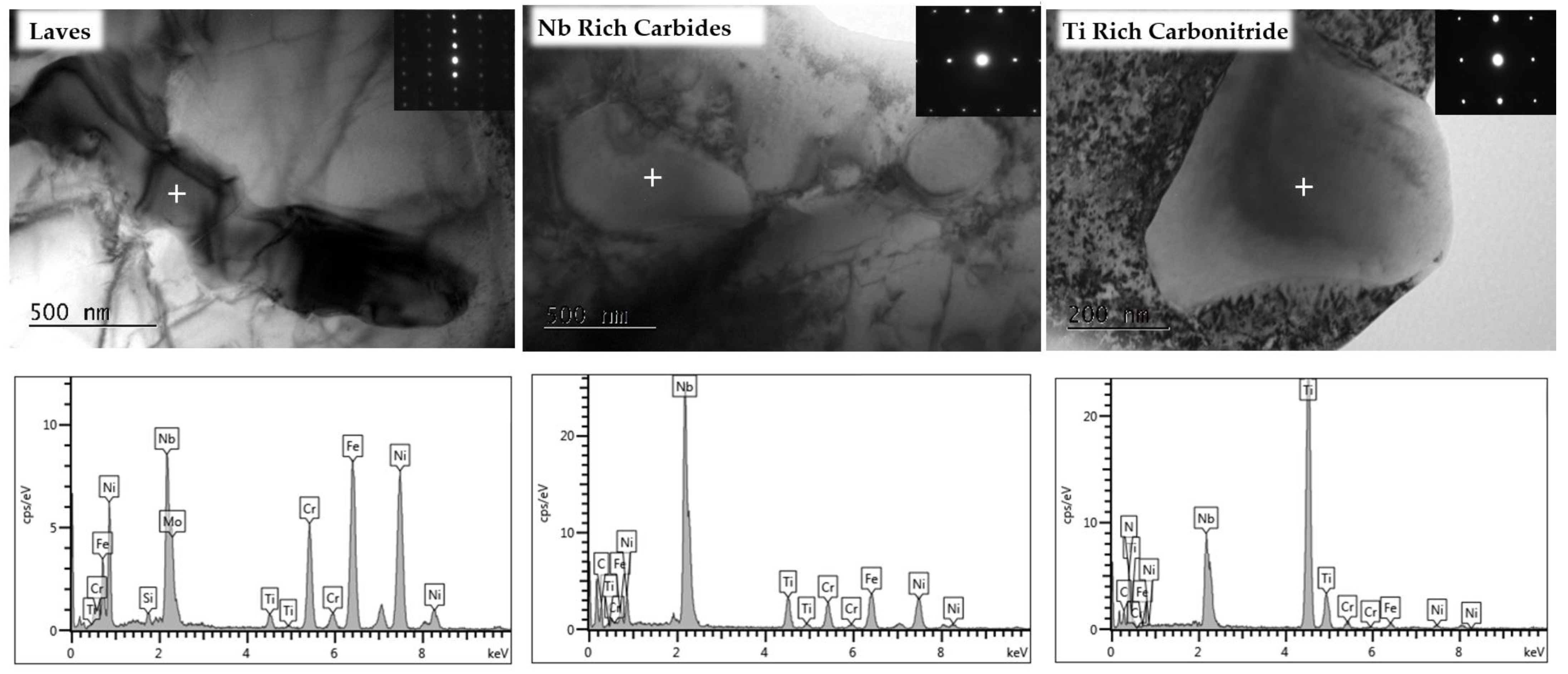
To further study the nature and crystalline structure of the developed precipitates in the FZ alloys, bright-field images via transmission electron microscopy, along with the corresponding selected area diffraction pattern (SAED), were obtained (
Figure 8). A significant number of dislocations within the dendritic
γ-matrix were detected. The phase composition of the matrix was confirmed by both electron diffraction and electron dispersive spectroscopy, whereas no
γ″ was detected in the weld matrix. Apart from the Ni matrix, three different secondary phases were observed, which appear to be a mixture of carbides, carbonitrides, and intermetallic inclusions.
Angular and cuboidal-shaped carbonitrides, rich in titanium, were detected inside the austenitic matrix. Quantitative EDS spot analysis revealed that Ti concentration in carbonitrides ranged from 53 to 55 wt%, whereas the corresponding values for Nb varied between 25–28 wt%. During the welding process, the material experiences a series of thermal cycles, including rapid heating in the fusion zone followed by controlled cooling. The heat input and cooling rates during welding affected the precipitation of various phases, including titanium-rich carbonitrides in the FZ. Nitrogen was present in the initial nickel superalloy, mainly in the form of titanium nitrides. Furthermore, both NbC and TiN are crystallized in FCC and present relatively similar lattice parameters. Since TiN and NbC are isomorphous and due to increased solubility, Ti-rich carbonitrides were probably developed through the primary carbide’s partial nucleation on pre-existing TiN particles [
10,
28], generating composite precipitates with a core of TiN.
Larger pure carbides of cubic structure, presenting a more complex morphology with an irregular shape, were detected most often at grain boundaries, with no crystallographic orientation relationship with the matrix. EDS analysis showed that MC is the predominant type, containing principally Nb, reaching 60 wt%, with also smaller amounts of Ti (≈7 wt%), Fe (≈9 wt%), Cr (≈6 wt%), Ni (≈8 wt%), and Mo (≈3 wt%). Regarding the third detected phase, the elemental content distribution indicated that those precipitates were enriched in Nb, Mo, and Si ((FeNiCr)2(NbMoTiSi)). They also presented a high Nb/Mo ratio, though their matrix was depleted of Cr. The hexagonal close-packed (HCP) structure of the precipitates under investigation was also confirmed by the corresponding SAED patterns.
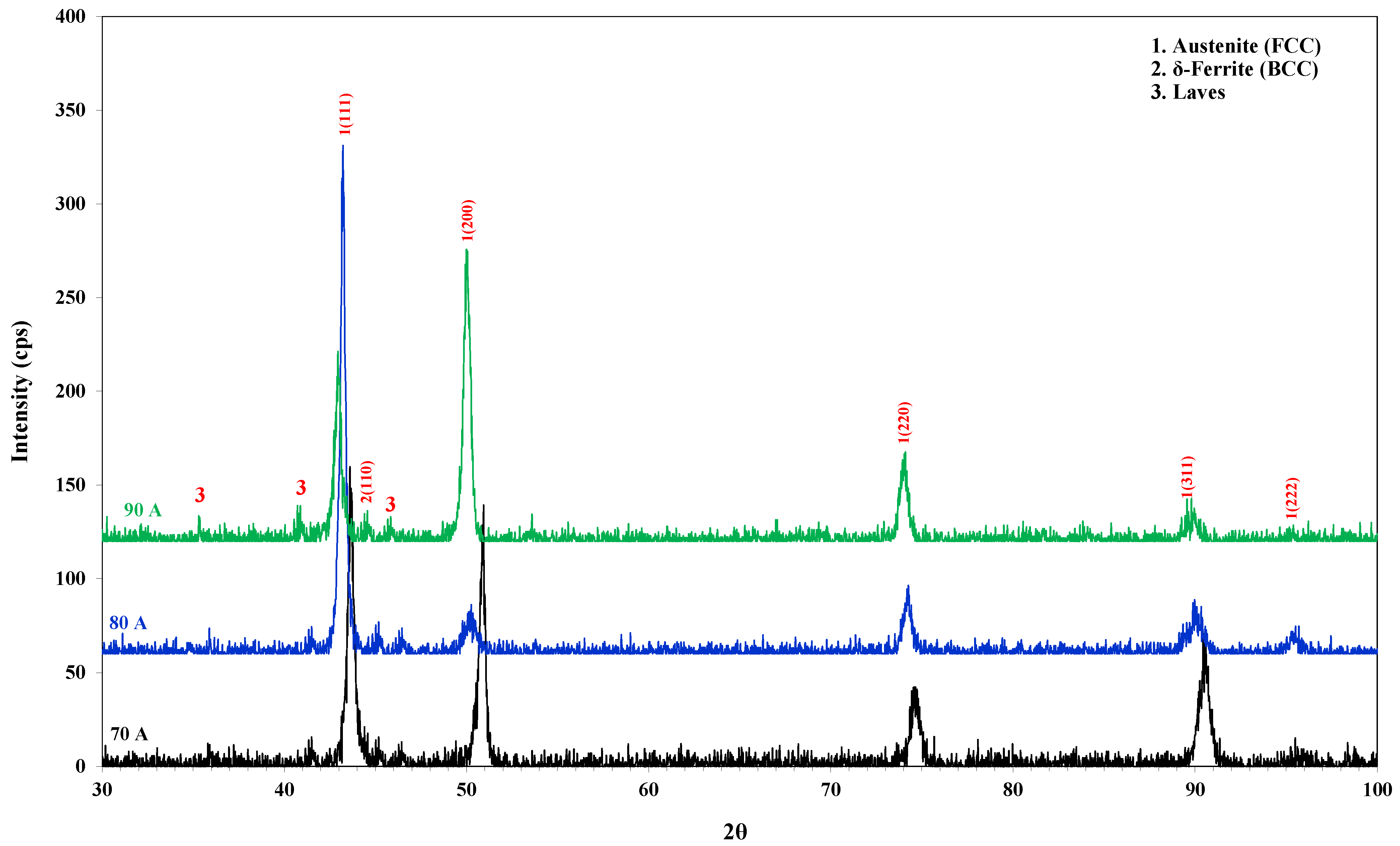
The above observations were also confirmed by the results of the XRD pattern analysis in the FZ, presented in
Figure 9. In all cases, the FZ mainly consisted of a pure face-centered cubic (FCC) solid solution. A systematic shift of the diffraction peaks towards lower diffraction Bragg’s angle was observed, indicating that increased heat input led to a crystal lattice parameter expansion (d value increment). Tensile residual stresses caused lattice distortions in the crystal structure in the FZ, which in turn led to shifts in the XRD peaks. The shift in peak position is related to the strain caused by the residual stresses; the greater the heat input, the higher the shift to a lower angle. Furthermore, the Laves phase was also observed as a minor constituent. The peaks seem to intensify with the increase in heat input and the consequent slower cooling rate. The Laves phase was identified as a Fe
2Nb type, with a lattice parameter of a = 4.8215 Å and c = 7.877 Å. This formation introduced brittle, topologically close-packed precipitates into the FZ microstructure, thus reducing its ductility and toughness. Those constituents may act as stress concentration points within the FZ, promoting crack initiation and propagation under mechanical stress, thus leading to increased susceptibility to fracture. Also, the XRD patterns revealed the existence of ferrite peaks (delta) that were developed during the transformation of austenite at elevated temperatures.
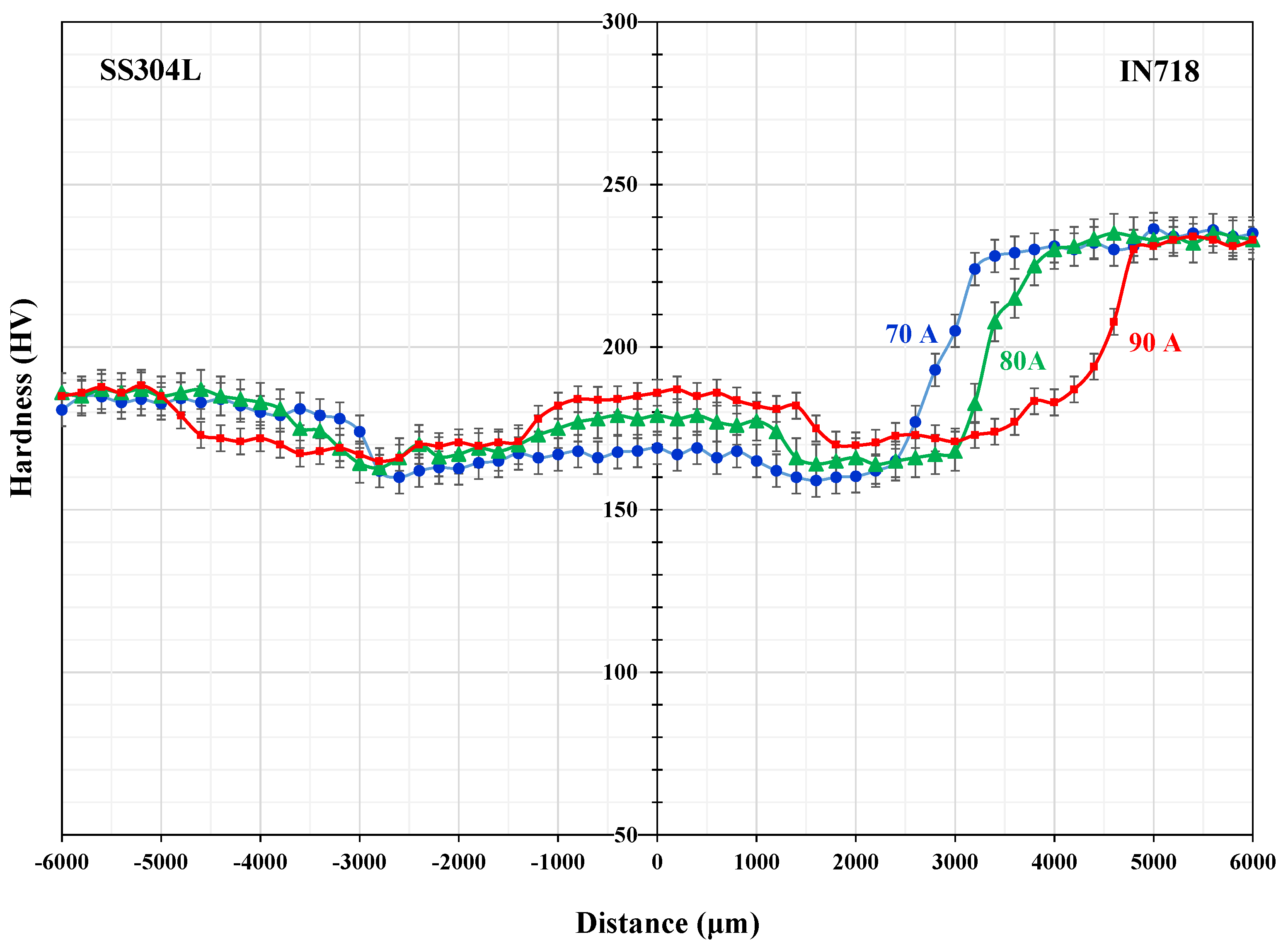
The hardness profile of the TIG joints at different welding currents carried out at a distance of 6 mm on either side, is presented in
Figure 10. The welds presented relatively higher hardness values (190–200 HV) with the corresponding values of the as-received austenitic SS304L (180–190 HV) but lower hardness than that of IN718 (about 230 HV). The peak hardness of about 200 HV was identified at the FZ of IN718, using a welding current of 90 A.
The increase in hardness, along with the increase in heat input, was attributed to elemental segregation and the development of a higher volume fraction of the brittle phases, such as Laves, at the grain boundaries. Furthermore, the existing Laves phase consumed a lot of niobium, thus reducing the available amount of Nb in the dendritic nickel solid solution. On the other hand, the hardness at HAZ exhibited relatively lower values with the welding current increase, mainly due to the grain growth phenomenon. Higher heat inputs resulted in slower cooling rates, also leading to the coarsening of the HAZ size.


