Article

Modeling the Evolution of Casting Defect Closure in Ingots through Radial Shear Rolling Processing

1
Core Facilities—Office the Provost, AEO Nazarbayev University, 53 Kabanbay Batyr Avenue, Astana 010000, Kazakhstan
2
Institute of Metallurgy and Ore Benefication, JSC, Satbayev University, 29/133 Shevchenko St., Almaty 050010, Kazakhstan
3
Department of Metallurgy, Faculty of Metallurgy and Mechanical Engineering, Karaganda Industrial University, 30 Republic Avenue, Temirtau 101400, Kazakhstan
4
Department of Production Management, Faculty of Engineering Production and Materials Technology, Częstochowa University of Technology, ul. J.H. Dąbrowskiego 69, 42-201 Częstochowa, Poland
*
Author to whom correspondence should be addressed.
Metals 2024, 14(1), 53; https://doi.org/10.3390/met14010053
Submission received: 11 November 2023 / Revised: 24 December 2023 / Accepted: 26 December 2023 / Published: 30 December 2023

Abstract

:
This paper investigates the behavior of transverse defects under significant total strain in conditions of complex vortex metal flow implemented through the radial shear rolling (RSR) method. The aim of this study is to assess the applicability of RSR processing for the in-depth transformation of small ingots of special steel into bars, particularly for the manufacturing of structural elements in specialized construction projects such as nuclear power plants. Although a substantial total strain is anticipated to enhance the steel structure and contribute to defect closure, the question of the development or closure of potential casting defects remains unclear. To address this issue, model tests were conducted to simulate the implementation of RSR processing. Defect behavior data under very complex vortex metal flow and high strain conditions were obtained for the first time and have scientific merit. A small steel ingot with a 32 mm diameter, containing a simulated artificial defect in the form of a transverse through-hole with a 5 mm diameter, was employed. During rolling, the workpiece diameter was progressively reduced by 2 mm with each subsequent pass, reaching a final diameter of 20 mm. Additionally, to provide a more detailed visualization of the defect evolution process, the same defect was modeled in an aluminum bar over six passes, and changes in defect volume and shape were analyzed after each pass. A highly detailed 3D visualization of the actual defect evolution was achieved based on cross-sections from experimental workpieces. These data corresponded to the total strain levels obtained by finite element method (FEM) simulation. Notably, a consistent similarity was observed between the test results for both metals, revealing a reduction in defect volume of up to 67.7%. The deformational welding of defects in the outer sections, encompassing one-third of the rod’s radius, occurred in the initial passes. However, defects in the axial zone of the rods remained unclosed, lengthening and gradually decreasing proportionally to the elongation of the rod, akin to conventional rolling. Consequently, the radial shear rolling (RSR) method is unsuitable for ingots with substantial discontinuities in the axial zone post-casting. Nevertheless, the method ensures the total welding of defects located in the outer zones of the ingots, even with minor applied deformations and a slight decrease in the diameter of the deformed ingot. Such data were obtained for the first time and should contribute to future investigations in this field.

1. Introduction

The validation of new alloys as structural products is a resource-intensive process, incurring significant expenses and demanding extensive labor. This is particularly evident when the research focuses on validating materials to meet the specific requirements of the nuclear industry. Such endeavors necessitate thorough testing, encompassing not only compliance with technical specifications but also including pre-reactor and reactor tests.
The materials destined for the core of nuclear reactors are distinguished by a specific level of purity concerning impurity composition. As a result, these materials are typically subjected to advanced melting techniques, including vacuum arc melting and electron beam melting [1].
The resultant materials exhibit elevated costs, and the subsequent deformation–heat treatment processes such as hot forging, hot pressing, cold rolling, and drawing contribute significantly to the overall expense of the final product. Typically, during the substantiation of new alloys, multiple compositions of ingots are concurrently melted. Moreover, these ingots are relatively small in size. Ingot variants with distinct chemical compositions demonstrate varying manufacturability characteristics; consequently, non-optimal parameters during subsequent deformation–heat treatment can compromise the quality and result in substantial metal losses in the form of chips [2].
To minimize material and time expenditures, it is recommended to employ deformation processing methods with a high intensity of deformation for treating the cast structure, coupled with minimal metal loss in chip form. The optimization of technological process parameters is most effectively achieved through the application of physical and mathematical modeling methods, validated by experimental testing conducted on actual equipment [3,4].
The main method for alloy steel manufacturing is founding. However, for specialized applications, steel is subjected to melting processes such as vacuum arc melting and electron beam melting. But casting has a number of disadvantages in terms of the discontinuity of ingots. The main defects in steel produced by casting are considered to be porosity, shrinkage cavities, microscopic gas bubbles in the volume of the material, etc. [5,6]. The authors of [7] demonstrate that gas pores in ingots produced through vacuum arc remelting (VAR) can vary in size, typically ranging up to 1.0 mm, and in certain instances, extending up to 10.0 mm. All of the acronyms used are available in Supplementary Materials S1-Acronyms list.
Plastic deformation is used in the defect treatment of casting or mechanical defects. The most popular method of plastic deformation in the mass production of steel bars is hot and cold rolling [8,9,10,11]. This technique is widely employed for the production of rods, reinforcement, wires, and various materials featuring a circular cross-section [12,13]. Drawing [14] and hot pressing [15] are alternative methods. Drawing finds its primary application in wire production [16] and occasionally in bar production [17], while hot pressing is mainly utilized for the production of complex cross-section short profiles [18]. However, these methods are labor-intensive and relatively low-tech. Additionally, they share a common drawback related to welding internal defects into the workpiece, attributable to elevated tensile stresses that hinder defect closure. While these methods are effective for welding small pores, they are less suitable for addressing larger defects [19,20,21,22]. The implications of these limitations extend to the properties of the final product and impact the economic aspects [22,23,24].
Besides the described conventional methods of plastic deformation, there is a separate type of material processing—severe plastic deformation (SPD) [25,26,27]. The most famous methods are equal channel angular pressing (ECAP), invented by Segal in 1972 [28,29]; high pressure torsion (HPT) [30,31], which is considered an improved version of the classic Bridgman anvil, invented in the beginning of the 20th century [32,33,34]; and isothermal all-round forging [35,36]. All of these methods began to gain popularity in the late 1990s with the start of the research by Prof. Valiev [37] and Prof. Langdon [38] and their work to achieve ultra-fine-grained (UFG) materials [39]. Subsequently, research began on the effect of SPD on the behavior of macro- and microdefects in the material. However, it is worth noting that the first two types of SPD (ECAP and HPT) cannot be used in the construction and industrial sectors with high consumption of materials, due to the impossibility of scaling the process, thereby showing their main drawback—limitations on the size of the workpiece and low manufacturability [40,41]. Another important disadvantage of ECAP is the inhomogeneity of processing of the sample’s edge sections during deformation, which are subsequently cut off and lead to a decrease in the metal utilization rate, which in turn shows the uneconomical nature of the process on an industrial scale [42]. As for the HPT process, the size limitation is completely unacceptable, usually 10 mm in diameter and 0.25–0.5 mm thick; it is noteworthy that experiments on the deformation of cylindrical samples were unsuccessful, which confirms the disadvantage of this method in terms of scaling up to industrial level [42]. The third type of SPD—isothermal all-round forging—is difficult to use due to the need for numerous turning operations and strict adherence to temperature conditions, which is very difficult to achieve on an industrial scale for the production of materials [43]. The main disadvantages of all of the types of SPD described above are limitations in the size of the workpieces and the inflexibility of the processes, which have actualized the search for new ways to use SPD to improve the structure of ingots.
A less conventional form of severe plastic deformation (SPD), which has yet to be widely adopted but is increasingly garnering interest among metallurgists and scientists, is radial shear rolling (RSR) [44,45,46]. This SPD method stands out for its potential scalability to an industrial level and its versatility in bar production, a particularly crucial feature for the manufacturing of structural elements in special construction industries, such as nuclear power plants (NPPs). The essence of this method lies in inducing substantial shear deformation, creating a vortex flow of metal during ingot processing, and establishing a favorable stress–strain state [47].
The three-roll RSR rolling scheme provides an extremely high level of deformation (more than 50 mm/mm for a full processing cycle). The stress–strain state of this process is different from conventional two-roll helical rolling for pipe piercing [48,49]. In RSR, there is no high level of tensile stresses in the central zone; they are balanced by compressive stresses. This fact, as well as the huge level of accumulated total strain, makes it possible to significantly change the sample structure to the UFG state, which was demonstrated in the work [50]. This, in turn, should have a positive effect on the closure and welding of macro- and microdefects. RSR was used for rolling stainless steel workpieces [51]. However, almost no one has studied the evolution and welding of defects in an ingot using RSR. This method has great flexibility of application, and the small size of the production machines makes it a suitable candidate for the flexible production of small batches of high-quality rods from special materials for the specific needs of a special facility under construction [52].
Studying the effect of deformation by the RSR method on the welding of casting defects in order to substantiate the possibility of using the method for processing small ingots of special steels is the goal of the work. The significance to the field of the conducted research lies in the fact that the data obtained on the behavior of volumetric defects during radial shear rolling will be useful for further modernization of this SPD method, in particular, when creating new roll designs that make it possible to increase the level of metal processing in one deformation cycle.

2. Materials and Methods

An experimental study of the artificial through transverse defect (in diameter) evolution was carried out to study the radial shear rolling process applicability range for special materials ingot processing. Such defect models are the most used for these purposes [53,54]. The main material for physical modeling was a small ingot of steel grade AISI-403 (12% Cr) smelted under the program for the development of new materials for nuclear power plant structures. In the future, this material is expected to be modified with yttrium to increase radiation resistance [55,56,57,58]. For this experiment, ordinary AISI-403 steel was melted in a vacuum furnace under a pressure of 100 Pa into an ingot with a diameter of 32 mm to fully match the cast dendritic structure of the real conventional ingots. This part, including the ingot properties, is described in more detail in the source [59].
In the ingot, a through transverse hole with a diameter of 5 mm (length 32 mm) was drilled along its diameter line. Experimental rolling was carried out on a radial shear rolling mill RSP-10/30 (MISIS, Moscow, Russia) and included hot rolling from one heating to 1200 °C along the route of reducing the diameters of the workpiece (mm) 32–30–28–26–24–22–20. The rolling mill technically allows for rolling workpieces up to a diameter of 13 mm. A final diameter of 20 mm was chosen to characterize the intermediate stages of the process. Heating was carried out in a Nabertherm LH-30/14 heating furnace (Nabertherm, Lilienthal, Germany). Each of the samples at the defect site was cut into disks with a cross-sectional thickness of 1 mm on a QATM Brilliant-220 precision cutting machine (QATM, Mammelzen, Germany) with a disk thickness of 0.6 mm. Then, the cut disks were numbered, scanned with a resolution of 1200 DPI, and imported into CAD KOMPAS-3D (version 22, ASCON, Saint Petersburg, Russia) to convert the drawings into vector graphics. Based on these sections, a 3D model of the defect was created, allowing us to visualize the shape evolution stage and determine the volume change. X-ray tomography methods were not used due to the low spatial resolution of most X-ray tomographs, which are limited by low accuracy—more than 1 mm [60,61]. This is especially important since a very complex defect shape is expected. The experimental setup RSR-10/30 and the method scheme are presented in Figure 1.
Due to the small amount of cast material and the laboriousness of working with it, an additional experiment was conducted to physically model the stages of evolution of a through transverse defect along rolling passes on AA1080 aluminum. The material under investigation was AA1080, an aluminum alloy consisting of Al (99.8 wt.%), Si (0.15 wt.%), Fe (0.15 wt.%), Zn (0.060 wt.%), Cu (0.030 wt.%), Ga (0.030 wt.%), Mn (0.020 wt.%), Ti (0.020 wt.%), and Mg (0.020 wt.%). The elastic (Young’s, tensile) modulus was 68 GPa, and the elongation at break was up to 34%. The fatigue strength was up to 50 MPa. The shear modulus was 26 GPa. The tensile strength at yield (proof) was up to 120 MPa [62].
In the workpieces, transverse holes with a diameter of 5 mm (length 25 mm) were drilled at equal distances. Additional modeling included sequential hot rolling of 2 workpieces (3 artificial defects in each) with one heating to 500 °C along the route of reducing the workpiece diameters (mm) 25–23–21–19–17–15–13. After reaching a diameter of 23 mm, the section containing the defect was cut off from the workpiece, and the workpiece was heated again and rolled to the next diameter of 21 mm. The steps were repeated according to the rolling pattern until the final diameter of 13 mm was achieved. Thus, data were obtained on 6 stages of closing a through defect when rolling a workpiece from 25 mm to 13 mm every 2 mm of diameter reduction. These data were then compared with rolling data from a real steel ingot containing the defect. Figure 2 shows images of rolled samples from both experiments.
To evaluation the completeness of the defect welding and changes in the microstructure, some sections were examined by scanning electron microscopy (SEM) on a JEOL JSM IT-200LA microscope (Jeol, Tokyo, Japan). Medium disc sections of 23 mm (first pass) and 13 mm (last pass) of aluminum and the medium disc section of the last pass of steel were studied. For sample preparation, these sections were additionally polished using a QATM SAPHIR 520 (QATM, Mammelzen, Germany) automatic grinding machine with a QATM RUBIN 500 head (QATM, Mammelzen, Germany).
Finite element method (FEM) computer simulations, so often used to study these processes, have had limited applicability here [63,64,65,66]. The fact is that, usually, the through defect closure simulation assumes uniform deformation by forging or conventional rolling with longitudinal workpiece section metal flow symmetry. Closure of the defect occurs (or does not occur) simultaneously throughout the entire volume of the defect, as shown in the work [63]. In the case of radial shear rolling, as was shown earlier [66], there is a large gradient of directions and velocities of metal flow across the cross section of the sample. The defect closes at the edges, forming a closed cavity, and after this, the simulation proceeds inadequately. A closed cavity having a closed volume does not change this volume, but only its shape. In reality, the air, of course, can compress and the cavity volume always decreases. Therefore, computer models were used only to visualize the stress–strain state at each stage of the experiment for a more correct interpretation of the experimental results obtained.
Computer simulation was carried out using the finite element method (FEM) in the Deform-3D software package (version 13.1.1, SFTC, Columbus, OH, USA). General parameters for both experimental simulations was next. The number of finite elements in both cases was set to 100,000. Workpiece type: plastic; tool type: rigid; finite element type: tetrahedral; thickening coefficient for finite elements in complex geometry zones (size ratio): 6 (i.e., the volume of elements in the hole zones was 6 times less than in the rest of the workpiece); calculation type: non-isothermal; ambient temperature: 20 °C; convective heat transfer coefficient to the environment: 20 W/(m2K); heat transfer coefficient between the workpiece and the rolls: 5000 W/(m2K); the angular speed of rotation of the rolls was 60 rpm; a time increment of 0.001 s per step was utilized. For contact interaction between the workpiece and the rolls, Siebel friction was employed with a coefficient of 1.0, representing the maximum roughened surface in the absence of lubrication. The calculation was conducted using a direct iterative method employing a sparse matrix solver for enhanced convergence at each step. The listed model interaction coefficients were selected according to those recommended in the program for the case of hot processing.
The simulation included sequential rolling along a route of decreasing billet diameters (mm) 25–23–21–19–17–15–13 for aluminum and 32–30–28–26–24–22–20 for a steel ingot and repeated the main experiment. The rolling temperature for aluminum was 500 °C, and for steel 1200 °C.
Modeled material selection was also different. The model for the aluminum-based experiment used the DEFORM-3D built-in database material—AA1080 aluminum alloy. The steel-based experiment used the self-created database in a previous experiment [59]. Based on Gleeble 3800 (Dynamic systems Inc., Austin, DX, USA) plastometer plastometric test results, the steel ingots’ stress–strain flow curve graphs regarding the 0.5–15 s−1 strain rate range and 600–1200 °C temperature range were plotted. To construct each curve, 3 tests were carried out. A total of 30 tests were carried out. The flow curves are also available in Supplementary Materials S2-Flow curves for steel.

3. Results and Discussion

The FEM simulation of RSR rolling for simple non-defected bars revealed a stress–strain distribution and shape-changing results corresponding to known data [66,67,68]. A high strain level on the periphery of the bar can be seen with a gradient to the first experiment (aluminum model) combined outputs in the axial zone. The stresses also have a gradient, but the tensile stresses are not over the compressive stresses. That is why defect welding by this method is possible. The velocity gradient of metal particles and the gradient in their direction of movement are important factors influencing defect closure and structural refinement. Figure 3 displays this point.
The simulation of the defective bar, as was described, failed, but we can show the results in Figure 4. Until the defect closes, it corresponds to a normal process, but afterward has problems.
It was one of the reasons for full-scale physical modeling conducted using aluminum as the model material. In unclear conditions, preference was given to the physical model, with verification on steel ingot. The defect-containing cross-section aluminum bar slices used for the through defect evolution visualization are shown in Figure 5. The full-scale images are available in Supplementary Materials S3-High-resolution cross-section images. The first experiment (aluminum model) combined outputs are shown in Figure 6. The 3D models’ STL files of defects are available in Supplementary Materials S4-Origianl STL-files for 3D models of defects. They are the results of the defect shape and volume evolution with the corresponding strain level data by FEM simulation.
The most obvious feature observed is that the through defect does not achieve complete closure. However, there was a substantial closure of the defect. The defect volume decreased from the initial 480 mm3 to 155 mm3. This is more than 67.7% of the original defect volume. The defect shape was transformed into the long and narrow state with the general volume decrease. It also can be seen that defect shape-changing is not simple and generally corresponds to Figure 3, which characterizes the moving directions of the metal particles. Also, it can be compared with the results of work [60]. The helical shape of the defect in the Ø17 bar can be clearly seen.
The other point is the abnormal defect disclosure outlier in Ø17 bar and its normal continuous closure afterward. It can be described by the general dynamic instability of the RSR process [68]. Also, according to the FEM simulation, the axial zone had a significant elongation trend, and the defect also was elongated like in a normal rolling process. The existing axial empty volume could be the stress concentration point. We suggest that this effect is not mandatory for each RSR case, but it is possible for some. The possibility of this effect should be accounted for in the industrial RSR implementation.
The next point is the correspondence between the defect closure process and the FEM simulation outputs. The strain level data alone have a bad connection. In this case, the most valuable is the metal flow direction mainly and connected stresses. For instance, the strain level for the outer zones of the 21 mm diameter bar and the axial zone of the final 13 mm diameter bar were the same, but in the first case, the defect zone was welded, unlike the second case. The high turbulence shear deformation outer zone provided the faster defect treatment in comparison with the most monotonous metal flow zone in the axial part, which resembled a normal conventional rolling process elongating defects with their slow closure. The last effect corresponded to [46] data and can be found in works for normal rolling transverse defects modeling [11,19]. These outputs were very similar. This scope proves that radial shear rolling is not worse than conventional rolling regarding the defect closure effect. Outer ingot zones had much better treatment, and the axial zone had the same treatment as achieved through conventional rolling. The modeled defect was very large and real casing defects were much smaller. Such processing should be sufficient for their treatment.
The last point is that the symmetrical peripheral through defect zones were completely welded very quickly in the first polling pass. In all stages, the defect volume was inside. The outer one-third of the bar radius was closed well for all of the RSR processing stages. The RSR method could be used for closing any surface defects within the outer one-third of the bar radius.
A microscopic study of an aluminum sample after the first rolling pass with a welded defect demonstrated a visually inconspicuous, incomplete closure of the defect on one side. Such microcracks could be not detected by non-destructive methods and serve as evidence for the selected study’s direct method. The area is shown in Figure 7.
The outer uncovered millimeter of the sample can be explained by a sticking deformation zone influenced by the interaction with the rolls. As can be seen from the evolution of the defect, these defects also closed (welded), but the closing process began at a depth of 1–3 mm from the edge. The defect was welded simultaneously over several millimeters of the radius. A recrystallized joint of short length was found in two places at once. The cross-section of the rod after the final rolling process exhibited a complete recrystallized joint. There were no cracks, as demonstrated in Figure 7.
The verification experiment with real stainless steel ingot RSR processing was conducted for 32 mm diameter ingots with the same 5 mm diameter perforation for transverse through defect modeling. The combined outputs of the second experiment (steel ingot model) are shown in Figure 8. The full-scale images are available in Supplementary Materials S3-High-resolution cross-section images. The 3D models (STL files) of defects are available in Supplementary Materials S4-Origianl STL-files for 3D models of defects.
As can be seen in the FEM simulation results for this experiment and the first experiment described in Figure 6, the final stage strain levels for both cases were similar. The defect shape was also generally similar, but in this case, a non-symmetrical, very thin (less than 1 mm) strip-shaped outlier could be observed. This outlier shape corresponds to the metal flow distribution through the bar cross-section shown in Figure 3. It can be described by the metal flow’s non-monotonous character and the RSR process’s dynamic instability due to the three-roll scheme used and the workpiece rotation [68]. Also, some of the local tensile stresses could occur when the helical shape of the defect did not correspond with the main metal flow helical trajectories of the next pass, potentially leading to a shift. We suggest that this effect can occur only for the through defect case only. A non-symmetric defect zone deformation probably occurs at that time. One part of the through defect perforation was already deformed, but the other part was still not deformed and caused some non-symmetry, which was the reason for the observed phenomena. The other fully welded bar half and the first experiment data can indirectly confirm this hypothesis. A separate experiment with non-through surface defects of various depths and juxtapositions could help to make this point clear.
On the other hand, a significant reduction in the defect volume was reached. The defect volume decreased from 620 mm3 to 380 mm3. This is a 40.3% reduction of the original defect volume.
The initial casted structure of the ingot and its after-rolling transformation are shown in Figure 9a. An after-rolling microscopic study was performed on the cross-sectional point highlighted in Figure 8 and shown in Figure 9b. This point was selected for checking for the possibility of microcracks, such as found in Figure 7. There were no microcracks. All of that wing of the defect was welded and recrystallized. There was a seamless and homogeneous mass of metal, indicating a successful fusion of the material. The initial classical dendrite casted structure was also completely transformed. No small gas bubbles—only small non-metallic inclusions—were detected.
The data obtained show the promise of the RSR method, but also reveal many new previously unknown problems that require further research. It is necessary to determine the effect of defect symmetry on its complete closure without cracks, and it is necessary to more accurately determine the scale factor for the depth and size of the surface defect.

4. Conclusions

Based on an analysis of the results of processing artificial drilled-through transverse defect models by radial shear rolling, the following conclusions were drawn, as summarized below:
  • The use of radial shear rolling processing led to decreases in defects and a change in the structure of a small ingot of stainless steel.
  • The artificial defect (by workpiece diameter) shape evolution showed significant elongation with a generally monotonous decrease in volume. The axial zone of the defect had elongation in the rolling direction, while the outer part of the defect underwent closure. The shape evolution and its helical peculiarities corresponded to solid workpiece radial shear rolling FEM simulation outputs. Radial shear rolling is not worse than conventional rolling regarding the defect closure effect. Outer ingot zones displayed much better treatment results, while those for the axial zone were similar to the results achieved with conventional rolling.
  • The modeling of artificial defect evolution demonstrated the possibility of decreasing defects by more than 67.7% of their original defect volume. The outer one-third of the bar radius in most cases was found to be defect-free. The modeled defect was substantial, whereas real casing defects were much smaller. Such processing should be sufficient for their treatment. However, the modeling outputs raised some new questions regarding the symmetry of the defect closure and the occurrence of microcracks. Further research in this direction is necessary. It can be concluded that processing can be improved.
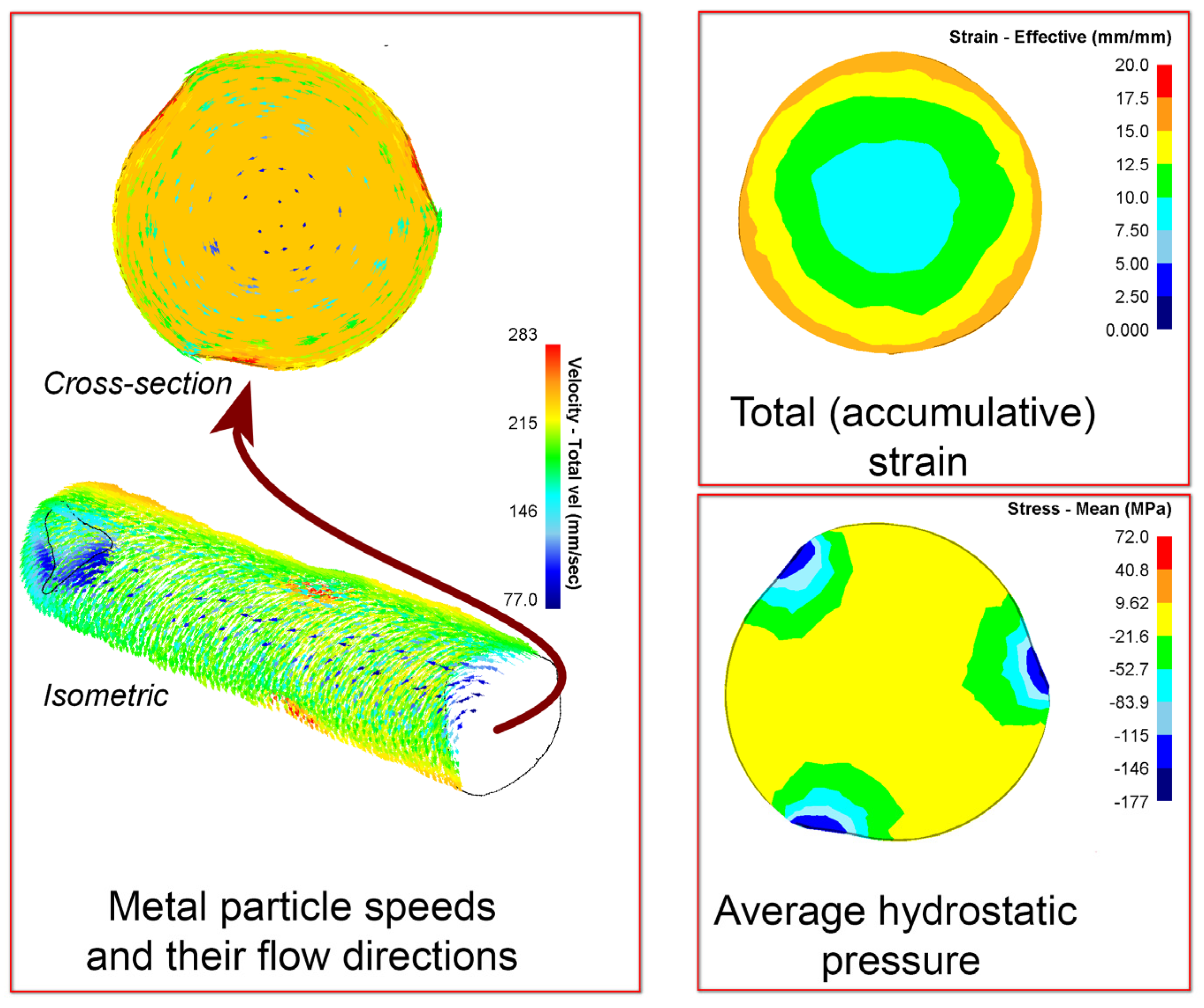
  • The strain level data alone were insufficient for defect closure prediction. This process for radial shear rolling cases mainly depends on the metal flow directions by the cross-section and their non-monotonicity.
  • The radial shear rolling process could be used for the improvement of small, special steel ingots intended for the direct manufacturing of bars for special structural elements.
  • Scientific data concerning the behavior of defects under very complex vortex metal flow and high strain conditions have been obtained for the first time and should contribute to future investigations in this field. This work will continue, especially with regard to clarifying the limits on the size of defects, taking into account the scale factor.

Supplementary Materials

The following supporting information can be downloaded at: https://www.mdpi.com/article/10.3390/met14010053/s1, Supplementary Materials S1: Acronyms list; Supplementary Materials S2: Flow curves for steel; Supplementary Materials S3: High-resolution cross-section images; Supplementary Materials S4: Original STL files for 3D models of defects.

Author Contributions

Conceptualization, writing, and funding acquisition, A.A.; methodology, A.P., A.K., K.O. and F.P.; formal analysis and sample preparation, N.L. and F.P.; writing—review and editing A.A. and F.P. All authors have read and agreed to the published version of the manuscript.

Funding

This research was funded by the Science Committee of the Ministry of Education and Science of the Republic of Kazakhstan (Grant No. AP09259982).

Data Availability Statement

The data presented in this study are available in [supplementary material].

Acknowledgments

The work was performed under the state budget-funded theme No. AP09259982 “Development and research of technology for obtaining and advance refinement of oxide dispersion-strengthened steel for use in nuclear engineering” of the program “Grant funding for young scientists on scientific and (or) scientific and technical projects for 2021–2023” (Customer—the Ministry of Education and Science of Republic of Kazakhstan). The authors would like to thank the Electron Microscopy Lab staff of Nazarbayev University Core Facilities team for their support with the microscopy work (Nurgul Danieva and Alisher Rapikov) and the Core Facilities head, Aidos Baumuratov.

Conflicts of Interest

The authors declare no conflicts of interest.

References

  1. Ioltukhovskiy, A.G.; Leontyeva-Smirnova, M.V.; Sokolov, N.B.; Kondratiev, V.P.; Zelenskiy, G.K. Development of New-Generation 12% Chromium Steels for Russian Nuclear Power Engineering. Issues At. Sci. Technol. Ser. Mater. Sci. New Mater. 2005, 1, 247. [Google Scholar]
  2. Pavlov, V.A.; Lozovaya, E.Y.; Babenko, A.A. Spetselectrometallurgy of Steels and Alloys: Textbook; Ural University Publishing House: Ekaterinburg, Russia, 2018. [Google Scholar]
  3. Kawałek, A.; Dyja, H.; Gałkin, A.M.; Ozhmegov, K.V.; Sawicki, S. Physical Modelling of the Plastic Working Processes of Zirconium Alloy Bars and Tubes in Thermomechanical Conditions. Arch. Metall. Mater. 2014, 59, 935–940. [Google Scholar] [CrossRef]
  4. Kawałek, K.; Dyja, H.; Galkin, A.M.; Ozhmegov, K.V.; Knapiński, M. Physical modelling of the plastic working processes of modified zr-nb zirconium alloy bars and tubes. Metalurgija 2015, 54, 79–82. [Google Scholar]
  5. Chelladurai, C.; Mohan, N.S.; Hariharashayee, D.; Manikandan, S.; Sivaperumal, P. Analyzing the Casting Defects in Small Scale Casting Industry. Mater. Today Proc. 2021, 37, 386–394. [Google Scholar] [CrossRef]
  6. Maisuradze, M.V.; Ryzhkov, M.A. Typical Engineering Steel Defects. Metallurgist 2021, 64, 1279–1287. [Google Scholar] [CrossRef]
  7. Banaszek, G.; Ozhmegov, K.; Kawalek, A.; Sawicki, S.; Magzhanov, M.; Arbuz, A. Investigation of the Influence of Hot Forging Parameters on the Closing Conditions of Internal Metallurgical Defects in Zirconium Alloy Ingots. Materials 2023, 16, 1427. [Google Scholar] [CrossRef] [PubMed]
  8. Park, J.-J. Effect of Shear Deformation on Closure of a Central Void in Thin-Strip Rolling. Mech. Mater. Trans. A 2016, 47, 479–487. [Google Scholar] [CrossRef]
  9. Park, J.-J. Prediction of Void Closure in a Slab during Various Deformation Processes. J. Mech. Sci. Technol. 2011, 25, 2871–2876. [Google Scholar] [CrossRef]
  10. Pietrzyk, M.; Kawalla, R.; Pircher, H. Simulation of the Behaviour of Voids in Steel Plates during Hot Rolling. Steel Res. 1995, 66, 526–529. [Google Scholar] [CrossRef]
  11. Cheng, R.; Zhang, J.; Wang, B. Closure Behavior of Spherical Void in Slab during Hot Rolling Process. Metall. Res. Technol. 2018, 115, 301. [Google Scholar] [CrossRef]
  12. Liu, D. The Control System of Modular Rolling Mill in High-Speed Bar Production Line. In Proceedings of the 2023 15th International Conference on Machine Learning and Computing, Zhuhai, China, 17–20 February 2023; ACM: New York, NY, USA, 2023; pp. 513–521. [Google Scholar]
  13. Farvees, M.; Raheem, S.; Thamboo, J.; Zahra, T.; Asad, M. Unconfined Bond Stress and Slip Characteristics of Steel Bars Embedded in Masonry Cement Mortars. Case Stud. Constr. Mater. 2023, 19, e02240. [Google Scholar] [CrossRef]
  14. Zelin, M. Microstructure Evolution in Pearlitic Steels during Wire Drawing. Acta Mater. 2002, 50, 4431–4447. [Google Scholar] [CrossRef]
  15. Zhang, S.; Song, H.; Zhang, F.; Liu, W. A New Integration of Hot Pressing and Carbon Partition Process to Produce High Strength Steel Components with Better Toughness. MATEC Web Conf. 2015, 21, 07005. [Google Scholar] [CrossRef]
  16. Nam, W.J.; Bae, C.M.; Oh, S.J.; Kwon, S.-J. Effect of Interlamellar Spacing on Cementite Dissolution during Wire Drawing of Pearlitic Steel Wires. Scr. Mater. 2000, 42, 457–463. [Google Scholar] [CrossRef]
  17. Atienza, J.M.; Martinez-Perez, M.L.; Ruiz-Hervias, J.; Mompean, F.; Garcia-Hernandez, M.; Elices, M. Residual Stresses in Cold Drawn Ferritic Rods. Scr. Mater. 2005, 52, 305–309. [Google Scholar] [CrossRef]
  18. Duan, Y.; Liu, W.; Ma, Y.; Cai, Q.; Zhu, W.; Li, J. Microstructure Characterization and Tensile Properties of Hot Isostatic Pressed China Ultrahigh Strength Steel. J. Mater. Res. Technol. 2020, 9, 15192–15201. [Google Scholar] [CrossRef]
  19. Chen, F.; Zhao, X.; Chen, H.; Ren, J. Void Closure Behavior during Plastic Deformation Using the Representative Volume Element Model. Appl. Phys. A 2020, 126, 685. [Google Scholar] [CrossRef]
  20. Chen, J.; Chandrashekhara, K.; Mahimkar, C.; Lekakh, S.N.; Richards, V.L. Void Closure Prediction in Cold Rolling Using Finite Element Analysis and Neural Network. J. Mater. Process. Technol. 2011, 211, 245–255. [Google Scholar] [CrossRef]
  21. Faini, F.; Attanasio, A.; Ceretti, E.; Giardini, C.; Trombini, F.; Viotto, L. Study of Void Closure in Hot Rolling of Stainless Steel Slabs. Procedia Eng. 2017, 207, 1397–1402. [Google Scholar] [CrossRef]
  22. Salehi, S.; Arashpour, M.; Kodikara, J.; Guppy, R. Sustainable Pavement Construction: A Systematic Literature Review of Environmental and Economic Analysis of Recycled Materials. J. Clean. Prod. 2021, 313, 127936. [Google Scholar] [CrossRef]
  23. Naotunna, C.N.; Samarakoon, S.M.S.M.K.; Fosså, K.T. Experimental Investigation of Crack Width Variation along the Concrete Cover Depth in Reinforced Concrete Specimens with Ribbed Bars and Smooth Bars. Case Stud. Constr. Mater. 2021, 15, e00593. [Google Scholar] [CrossRef]
  24. Wong, E.T.T.; Norman, G. Economic Evaluation of Materials Planning Systems for Construction. Constr. Manag. Econ. 1997, 15, 39–47. [Google Scholar] [CrossRef]
  25. Sakai, T.; Belyakov, A.; Kaibyshev, R.; Miura, H.; Jonas, J.J. Dynamic and Post-Dynamic Recrystallization under Hot, Cold and Severe Plastic Deformation Conditions. Prog. Mater. Sci. 2014, 60, 130–207. [Google Scholar] [CrossRef]
  26. Valiev, R.Z.; Islamgaliev, R.K.; Alexandrov, I.V. Bulk Nanostructured Materials from Severe Plastic Deformation. Prog. Mater. Sci. 2000, 45, 103–189. [Google Scholar] [CrossRef]
  27. Valiev, R.Z.; Korznikov, A.V.; Mulyukov, R.R. Structure and Properties of Ultrafine-Grained Materials Produced by Severe Plastic Deformation. Mater. Sci. Eng. A 1993, 168, 141–148. [Google Scholar] [CrossRef]
  28. Segal, V.M. The Method of Material Preparation for Subsequent Working. Patent No. 575892, 1977. [Google Scholar]
  29. Segal, V.M. Equal Channel Angular Extrusion: From Macromechanics to Structure Formation. Mater. Sci. Eng. A 1999, 271, 322–333. [Google Scholar] [CrossRef]
  30. Strangward-Pryce, G.; Song, K.; Mizohata, K.; Hofmann, F. The Effect of High-Pressure Torsion on Irradiation Hardening of Eurofer-97. Nucl. Mater. Energy 2023, 36, 101468. [Google Scholar] [CrossRef]
  31. Ni, H.; Ding, C.; Wang, H.; Lv, S.; Wang, X.; Liu, Y. The Evolutions of Microstructure, Texture and Hardness of A1050 Deformed by HPT at the Transition Area. Materials 2023, 16, 4686. [Google Scholar] [CrossRef]
  32. Bridgman, P.W. On Torsion Combined with Compression. J. Appl. Phys. 1943, 14, 273–283. [Google Scholar] [CrossRef]
  33. Bridgman, P.W. Shearing Phenomena at High Pressures, Particularly in Inorganic Compounds. Proc. Am. Acad. Arts Sci. 1937, 71, 387. [Google Scholar] [CrossRef]
  34. Bridgman, P.W. Effects of High Shearing Stress Combined with High Hydrostatic Pressure. Phys. Rev. 1935, 48, 825–847. [Google Scholar] [CrossRef]
  35. Sitdikov, O.; Sakai, T.; Goloborodko, A.; Miura, H.; Kaibyshev, R. Effect of Pass Strain on Grain Refinement in 7475 Al Alloy during Hot Multidirectional Forging. Mater. Trans. 2004, 45, 2232–2238. [Google Scholar] [CrossRef]
  36. Gamin, Y.V.; Skugorev, A.V.; Karashaev, M.M.; Kin, T.Y.; Galkin, S.P.; Mahmoud Alhaj Ali, A.; Cheverikin, V.V. Analysis of Microstructure Evolution of Co-Cr-Mo Alloy during Isothermal Forging. Metals 2023, 13, 1583. [Google Scholar] [CrossRef]
  37. Valiev, R.Z.; Alexandrov, I.V.; Islamgaliev, R.K. Processing and Properties of Nanostructured Materials Prepared by Severe Plastic Deformation. In Nanostructured Materials; Chow, G.-M., Noskova, N.I., Eds.; Springer: Dordrecht, The Netherlands, 1998; pp. 121–142. ISBN 978-94-010-6100-1. [Google Scholar]
  38. Langdon, T.G. Twenty-Five Years of Ultrafine-Grained Materials: Achieving Exceptional Properties through Grain Refinement. Acta Mater. 2013, 61, 7035–7059. [Google Scholar] [CrossRef]
  39. Valiev, R.Z.; Langdon, T.G. Principles of Equal-Channel Angular Pressing as a Processing Tool for Grain Refinement. Prog. Mater. Sci. 2006, 51, 881–981. [Google Scholar] [CrossRef]
  40. Faraji, G.; Kim, H.S. Review of Principles and Methods of Severe Plastic Deformation for Producing Ultrafine-Grained Tubes. Mater. Sci. Technol. 2017, 33, 905–923. [Google Scholar] [CrossRef]
  41. Zayed, E.M.; Shazly, M.; El-Sabbagh, A.; El-Mahallawy, N.A. Deformation Behavior and Properties of Severe Plastic Deformation Techniques for Bulk Materials: A Review. Heliyon 2023, 9, e16700. [Google Scholar] [CrossRef]
  42. Sakai, G.; Nakamura, K.; Horita, Z.; Langdon, T.G. Developing High-Pressure Torsion for Use with Bulk Samples. Mater. Sci. Eng. A 2005, 406, 268–273. [Google Scholar] [CrossRef]
  43. Jiang, H.; Liu, Y.; Wu, Y.; Zhao, K.; Shan, D.; Zong, Y. Grain Refinement Mechanism and Microstructural Evolution of M50NiL Steel during Multi-Directional Impact Forging. J. Mater. Eng. Perform 2019, 28, 3505–3516. [Google Scholar] [CrossRef]
  44. Galkin, S.P. Regulating radial-shear and screw rolling on the basis of the metal trajectory. Steel Transl. 2004, 4, 57–60. [Google Scholar]
  45. Troitskii, D.V.; Gamin, Y.V.; Galkin, S.P.; Budnikov, A.S. Parametric Model of a Three-Roll Unit of Radial-Shear Rolling Mini-Mill. Izv. Vysš. Učebn. Zaved. Cern. Met. 2023, 66, 376–386. [Google Scholar] [CrossRef]
  46. Lezhnev, S.N.; Naizabekov, A.B.; Volokitina, I.E.; Panin, E.A.; Kuis, D.V. Recycling of Stainless Steel Bar Scrap by Radial-Shear Rolling to Obtain an Ultrafine-Grained Gradient Structure. Litʹë Met. 2021, 2, 61–67. [Google Scholar] [CrossRef]
  47. Arbuz, A.; Kawalek, A.; Ozhmegov, K.; Dyja, H.; Panin, E.; Lepsibayev, A.; Sultanbekov, S.; Shamenova, R. Using of Radial-Shear Rolling to Improve the Structure and Radiation Resistance of Zirconium-Based Alloys. Materials 2020, 13, 4306. [Google Scholar] [CrossRef] [PubMed]
  48. Berazategui, D.A.; Cavaliere, M.A.; Montelatici, L.; Dvorkin, E.N. On the Modelling of Complex 3D Bulk Metal Forming Processes via the Pseudo-Concentrations Technique. Application to the Simulation of the Mannesmann Piercing Process. Int. J. Numer. Meth. Eng. 2006, 65, 1113–1144. [Google Scholar] [CrossRef]
  49. Cho, J.M.; Kim, B.S.; Moon, H.K.; Lee, M.C.; Joun, M.S. Comparative Study on Mannesmann Roll Piercing Processes between Diescher’s Guiding Disk and Stiefel’s Guiding Shoe. In Proceedings of the 11th International Conference on Numerical Methods in Industrial Forming Processes: NUMIFORM 2013, Shenyang, China, 6–10 July 2013; pp. 843–849. [Google Scholar]
  50. Lezhnev, S.N.; Naizabekov, A.B.; Panin, E.A.; Volokitina, I.E.; Arbuz, A.S. Graded Microstructure Preparation in Austenitic Stainless Steel during Radial-Shear Rolling. Metallurgist 2021, 64, 1150–1159. [Google Scholar] [CrossRef]
  51. Naizabekov, A.; Lezhnev, S.; Arbuz, A.; Panin, E. The Effect of Radial-Shear Rolling on Microstructure and Mechanical Properties of Stainless Austenitic Steel AISI-321. MATEC Web Conf. 2018, 190, 11003. [Google Scholar] [CrossRef]
  52. Ding, X.; Sun, L.; Huang, X.; Zhao, Z. Research on Three-Roll Screw Rolling Process for Ti6Al4V Titanium Alloy Bar. High Temp. Mater. Process. 2019, 38, 178–182. [Google Scholar] [CrossRef]
  53. Dmitriev, S.; Malikov, V.; Ishkov, A. The Steel Defects Investigation by the Eddy Current Method. IOP Conf. Ser. Mater. Sci. Eng. 2019, 698, 066045. [Google Scholar] [CrossRef]
  54. Kadykov, V.N.; Umanskii, A.A.; Mart’yanov, Y.A. Study of surface deformation during rolling of the bar calibers. Izv. Vysš. Učebn. Zaved. Cern. Met. 2015, 56, 8. [Google Scholar] [CrossRef]
  55. Klueh, R.L.; Shingledecker, J.P.; Swindeman, R.W.; Hoelzer, D.T. Oxide Dispersion-Strengthened Steels: A Comparison of Some Commercial and Experimental Alloys. J. Nucl. Mater. 2005, 341, 103–114. [Google Scholar] [CrossRef]
  56. Suryanarayana, C. Mechanical alloying and milling. Prog. Mater. Sci. 2001, 46, 1–184. [Google Scholar] [CrossRef]
  57. Ukai, S.; Fujiwara, M. Perspective of ODS Alloys Application in Nuclear Environments. J. Nucl. Mater. 2002, 307–311, 749–757. [Google Scholar] [CrossRef]
  58. Hampel, U.; Babout, L.; Banasiak, R.; Schleicher, E.; Soleimani, M.; Wondrak, T.; Vauhkonen, M.; Lähivaara, T.; Tan, C.; Hoyle, B.; et al. A Review on Fast Tomographic Imaging Techniques and Their Potential Application in Industrial Process Control. Sensors 2022, 22, 2309. [Google Scholar] [CrossRef] [PubMed]
  59. Arbuz, A.; Kawalek, A.; Panichkin, A.; Ozhmegov, K.; Popov, F.; Lutchenko, N. Using the Radial Shear Rolling Method for Fast and Deep Processing Technology of a Steel Ingot Cast Structure. Materials 2023, 16, 7547. [Google Scholar] [CrossRef]
  60. Skripalenko, M.M.; Rogachev, S.O.; Bazhenov, V.E.; Romantsev, B.A.; Skripalenko, M.N.; Karpov, B.V.; Titov, A.Y.; Koltygin, A.V.; Danilin, A.V. Research of Three-High Screw Rolling of Aluminum Billets with Copper Inserts at Different Rolls Feed Angles. Metals 2023, 13, 1671. [Google Scholar] [CrossRef]
  61. Faini, F.; Attanasio, A.; Ceretti, E. Experimental and FE Analysis of Void Closure in Hot Rolling of Stainless Steel. J. Mater. Process. Technol. 2018, 259, 235–242. [Google Scholar] [CrossRef]
  62. EN 485-2; Aluminium and Aluminium Alloys. Sheet, Strip and Plate. Mechanical Properties. European Standard; European Committee for Standardization: Brussels, Belgium, 2007.
  63. Lee, Y.S.; Lee, S.U.; Van Tyne, C.J.; Joo, B.D.; Moon, Y.H. Internal Void Closure during the Forging of Large Cast Ingots Using a Simulation Approach. J. Mater. Process. Technol. 2011, 211, 1136–1145. [Google Scholar] [CrossRef]
  64. Arbuz, A.; Kawalek, A.; Ozhmegov, K.; Panin, E.; Magzhanov, M.; Lutchenko, N.; Yurchenko, V. Obtaining an Equiaxed Ultrafine-Grained State of the Longlength Bulk Zirconium Alloy Bars by Extralarge Shear Deformations with a Vortex Metal Flow. Materials 2023, 16, 1062. [Google Scholar] [CrossRef]
  65. Lezhnev, S.; Naizabekov, A.; Kuis, D.; Kasperovich, A.; Panin, E. Modeling of the Rebar Products Recycling Technology by Radial-Shear Rolling and Drawing. In Proceedings of the 30th Anniversary International Conference on Metallurgy and Materials, Brno, Czech Republic, 26–28 May 2021; pp. 193–198. [Google Scholar]
  66. Lopatin, N.V.; Salishchev, G.A.; Galkin, S.P. Mathematical Modeling of Radial-Shear Rolling of the VT6 Titanium Alloy under Conditions of Formation of a Globular Structure. Russ. J. Non-Ferr. Met. 2011, 52, 442–447. [Google Scholar] [CrossRef]
  67. Dobatkin, S.; Galkin, S.; Estrin, Y.; Serebryany, V.; Diez, M.; Martynenko, N.; Lukyanova, E.; Perezhogin, V. Grain Refinement, Texture, and Mechanical Properties of a Magnesium Alloy after Radial-Shear Rolling. J. Alloys Compd. 2019, 774, 969–979. [Google Scholar] [CrossRef]
  68. Galkin, S.P. Radial Shear Rolling as an Optimal Technology for Lean Production. Steel Transl. 2014, 44, 61–64. [Google Scholar] [CrossRef]
Figure 1. Experimental setup RSR-10/30 (a) and the radial shear rolling method scheme (b).
Metals 14 00053 g001
Figure 2. The after-rolled samples by the rolling stages for both experiments.
Metals 14 00053 g002
Figure 3. FEM simulation RSR processing stress–strain and metal flow characterization.
Metals 14 00053 g003
Figure 4. The transverse through defect by RSR processing simulation.
Metals 14 00053 g004
Figure 5. The defect-containing cross-section aluminum bar slices used for the through defect evolution visualization.
Metals 14 00053 g005
Figure 6. Visualization of the defect-containing aluminum bar evolution.
Metals 14 00053 g006
Figure 7. Various scale microscopic images of the defect closure zone after the first RSR processing pass.
Metals 14 00053 g007
Figure 8. The through defect shape on the stainless steel ingot model after rolling by RSR.
Metals 14 00053 g008
Figure 9. Various scale microscopic images of steel ingot: (a) initial structure; (b) after the final RSR processing pass.
Metals 14 00053 g009
Disclaimer/Publisher’s Note: The statements, opinions and data contained in all publications are solely those of the individual author(s) and contributor(s) and not of MDPI and/or the editor(s). MDPI and/or the editor(s) disclaim responsibility for any injury to people or property resulting from any ideas, methods, instructions or products referred to in the content.

