Abstract
In this paper, in order to achieve the development of a novel biodegradable dual-phase alloy in a Ca–Mg–Zn system, the establishment of the control strategy of degradation behavior of alloys composed of two phases was attempted by the control of alloy composition, constituent phases, and microstructure. By combining two phases with different dissolution behavior, biodegradable alloys are expected to exhibit multiple functions. For example, combining a suitable slow dissolving phase with a faster dissolving second phase may allow for dynamical concavities formation during immersion on the surface of the alloy, assisting the invasion and establishment of bone cells. Without the careful control of the microstructure, however, there is a risk that such dual-phase alloy rapidly collapses before the healing of the affected area. In this study, ten two-phase alloys consisting of various different phases were prepared and their degradation behaviors were examined. Consequently, it was found that by combining the IM3 and IM1 intermetallic phases with the compositions of Ca2Mg5Zn13 and Ca3Mg4.6Zn10.4, the expected degradation behavior can be obtained.
1. Introduction
Currently, Ti alloys and Co–Cr alloys with excellent mechanical properties, corrosion resistance, and biocompatibility are widely used in the field of biomaterials as bone reinforcement implant materials [1]. However, in several cases, the surgical removal of these implants is necessary after the affected area has healed. In such cases, the use of in-vivo biodegradable materials that are soluble in biological environments has been considered [2]. Magnesium alloys have been the most studied candidates for such materials [3,4,5,6,7,8,9,10,11,12]; however, their high degradation rate needs to be controlled. The usage of Ca–Mg–Zn ternary alloy is as the focus of an alternative strategy [13,14,15,16,17,18,19,20,21,22,23,24,25] as it contains Ca, which is an essential element for living organisms, and Zn, which exists in trace amounts in the body. Zn is considered an essential mineral in the human body, and it is important for the proper functioning of numerous enzymes and for supporting immune functions, protein and DNA synthesis, and wound healing [7,26]. Among the studies, we particularly focused on the use of intermetallic compounds. Generally, the intermetallic compounds are used to improve the mechanical properties of the structural materials, for example [27,28,29,30,31,32]. However, we focused on using the intermetallic compounds to control the degradation behavior of the alloys [14,33].
In this study, we investigated the feasibility of developing a new biodegradable “dual-phase” alloy, which consists of two phases with different solubilities, in a Ca–Mg–Zn system. As shown in Figure 1, through the coexistence of electrochemically less noble second phase in the form of islands in a relatively noble matrix phase, a biodegradable dual-phase alloy can be developed. A slow-dissolving phase remains until late dissolution and acts as a scaffold for the cell by creating surface irregularities. In contrast, the preferential dissolution of the faster-dissolving second phase continuously releases Ca ions and other substances that are necessary for bone regeneration. This paper reports the current progress in the development of such dual-phase alloys and presents their future prospects.
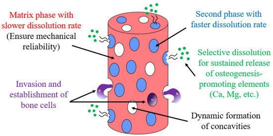
Figure 1.
Model for the development of a biodegradable dual-phase alloy.
2. Materials and Methods
Ten forms of master alloys with varying Ca–Mg–Zn compositions were used as dual-phase alloys. Many of them focused on in this study are Zn-rich alloys. The alloy compositions used in this study are listed in Table 1, and a detailed explanation of the alloy composition is provided in Section 3.1. The ingots were prepared by melting high-purity raw Ca, Mg, and Zn pellets in carbon crucibles. The carbon crucible was sealed by quartz-tube filled with Ar, and the melting of the raw materials was conducted, followed by air cooling. The size of prepared ingot was ϕ12 mm × ~50 mm and the central part of the ingot was used for testing. The prepared ingots were then heat-treated at 335 °C for 2 weeks to obtain thermally stable phases. The constituent phases of the alloys were determined by compositional analysis using a scanning electron microscope with energy-dispersive X-ray spectroscopy (SEM-EDS, JEOL, JEM-6500F, Tokyo, Japan). In addition, X-ray diffraction (XRD) measurement was conducted by using Cu-Kα radiation. To prepare the specimens for microstructure observation, the specimen surfaces were mechanically polished by emery paper, and then etched with an ethanol-20 vol% nitric acid solution at ~10 °C. Immersion tests were performed on the prepared alloys according to ASTM-G31-72 [34] in Hanks’ balanced salt solution (HBSS, Gibco, Thermo Fisher Scientific, Waltham, MA, USA), which was used as a simulated body fluid. The composition of the Hanks’ balanced salt solution is indicated in the Supplementary Table S1. Specimens with dimensions of approximately 7 × 7 × 2 mm3 were cut using an electrodischarge machine. The specimens were then immersed in the solution with a volume per surface area of 40 mL/cm2, and the temperature was maintained at 37 °C using a water bath. The immersed specimens were removed from the solution after several different immersion periods, and changes in the surface morphologies resulting from immersion were examined using optical microscopy (OM), and laser microscopy (LM).

Table 1.
Compositions of the dual-phase alloys prepared in this study.
In addition, galvanic current density measurements were performed in accordance with ASTM-G71-81 [35] to understand the factors controlling the dissolution behaviors of the dual-phase alloys. The measurements were performed on an electro-chemical workstation (VersaSTAT 4, Toyo Corporation, Tokyo, Japan) at a temperature of 37 °C in the Hanks’ solution. Each anode and cathode were composed of a single phase of the compound. The circuit was closed after the open-circuit potential was measured for 30 min, and then the galvanic current was measured for 120 min. During the measurement, the area of the anode was kept constant at 0.32 cm2, and the variation in the dissolution behavior was examined by changing the area of the cathode.
3. Results and Discussion
3.1. Microstructure and Degradation Behavior of Zn–Mg–Ca Dual-Phase Alloys
Wide variations in the degradation behavior of intermetallic compounds in the Ca–Mg–Zn system have been previously reported [14], by the study using the single-phase alloys. In addition to many binary compounds, four Ca–Mg–Zn ternary compounds, namely IM1, IM2, IM3, and IM4, exist. The compositions of IM1, IM2, IM3, and IM4 are approximately Ca3MgxZn15−x (4.6 ≤ x ≤ 12), Ca14.5Mg15.8Zn69.7, Ca2Mg5Zn13, and Ca1.5Mg55.3Zn43.2, respectively [36]. A previous study demonstrated that the degradation behavior of Ca–Mg–Zn alloy samples composed of “one intermetallic phase” was approximately classified into four groups in the ternary phase diagram [14]. The degradation behavior was predominantly affected by the Ca-content and secondarily by the amount of Zn. As Ca decreases and Zn increases in the phase composition, the degradation rate also decreases [14]. This can be clearly understood by the variations in the corrosion potential and corrosion rate estimated from their polarization curves according to the equation shown in [14], as shown in Figure 2.
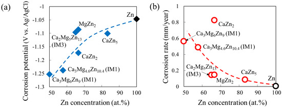
Figure 2.
Variations in (a) corrosion potential and (b) corrosion rate with Zn concentration estimated from the polarization curves of single-phase alloy samples in Ca–Mg–Zn ternary system.
Figure 3 shows the alloy compositions focused on in this study, indicated on the Ca–Mg–Zn ternary phase diagram at 335 °C reported by Zhang et al. [36,37]. In the ternary phase diagram, the two-phase region focused on in this study is colored blue, and the constituent phase in the alloy (single-phase region) is colored green. Based on a previous report on the degradation behavior of single-phase alloys [14], eight different dual-phase alloys, named samples A–H, were first prepared, as indicated by the open circles in Figure 3.
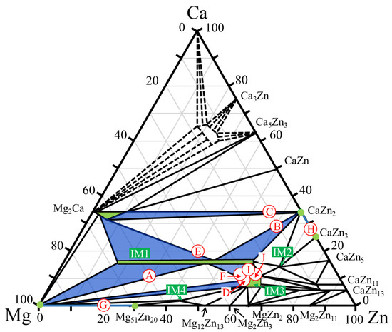
Figure 3.
Compositions of the dual-phase alloys A–J investigated in this study. The compositions are plotted on the Ca–Mg–Zn ternary phase diagram previously presented by Zhang et al. [36,37].
Figure 4 shows the XRD profiles obtained from the prepared samples. The phases expected from the phase diagram reported by Zhang et al. [36,37] were confirmed to be formed in all dual-phase alloys. The identification of the constituent phases was further conducted by the SEM-EDS analysis. Figure 5 shows the SEM images of the microstructures of the alloy samples. The measured results of SEM-EDS are presented in Table 2. The same conclusion obtained by the XRD measurement was drawn. The formation of the third phase was observed in some alloys because of the slight deviation in alloy composition during the alloy preparation process; however, its amount was extremely small except for that in sample A, in which some amount of IM3 formation (Point c) was observed in the IM1/Mg dual microstructure. Depending on the alloy composition, the microstructures of the dual-phase alloys exhibited different morphologies, and they were classified into three groups. The alloys composed of IM1/Mg (Sample A), CaZn2/IM1 (Sample B), and CaZn2/Mg2Ca (Sample C) are classified into Group I. In the alloys belonging to Group I, the noble phase crystallized in the electrochemically less noble matrix phase. This contradicts the ideal microstructure shown in Figure 1.
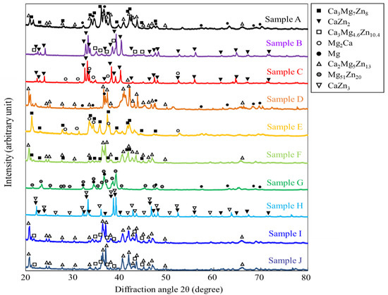
Figure 4.
XRD profiles taken from the specimens prepared in this study. The measurements were conducted by using the powder prepared from the specimens.
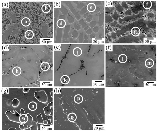
Figure 5.
Microstructures in the prepared alloys: (a) Sample A, (b) Sample B, (c) Sample C, (d) Sample D, (e) Sample E, (f) Sample F, (g) Sample G, and (h) Sample H. At the points a–q indicated by white circles, SEM-EDS composition analyses were conducted.
Table 2.
Compositions in at.% examined by SEM-EDS at the points indicated in Figure 4 and the expected constituent phases in the alloys.
The alloys composed of IM3/Mg (Sample D) and IM1/Mg2Ca (Sample E) belong to Group II. They exhibited two-phase microstructures with an ideal matrix consisting of noble phases. However, the less noble second phase has a network microstructure with mesh-like connections between the grains. In such a microstructure, a risk of the slow-dissolving phase with a noble corrosion potential becoming desorbed and diverging into the body during the dissolution of the alloy exists, which is undesirable for the biodegradable alloy developed in this study.
The alloys composed of IM3/IM1 (Sample F), Mg51Zn20/Mg (Sample G), and CaZn3/CaZn2 (Sample H) belong to Group III. In contrast to the alloys belonging to Group I and II, they exhibited relatively ideal microstructures, in which a porous structure was expected to develop on the surface over time while maintaining the bulk morphology during the progress of the dissolution reaction. Therefore, alloys belonging to Group III are the most promising for development as new dual-phase biodegradable alloys. Among them, the degradation behavior of Sample F, which was composed of IM3/IM1 phases in the Ca–Mg–Zn ternary system, was further examined in this study.
Figure 6a shows an OM image of the surface morphology of Sample F immersed in Hanks’ solution for 250 h. As expected, Sample F retained its bulk morphology even after 250 h of immersion. By maintaining the bulk shape, the formation of concavities was observed on the sample surface due to the progression of corrosion of the second IM1 phase. Figure 6b and Table 3 show the SEM image and composition analysis results for the surface of the immersed sample. The formation of calcium phosphate, which is expected to assist bone formation, was observed near the concavities, associated with the preferential corrosion of the IM1 phase. The problem, however, is that cracks frequently formed around the concavities in the microstructure, as indicated by the arrows in Figure 6a. Therefore, further dissolution can lead to significant deterioration in the mechanical properties.
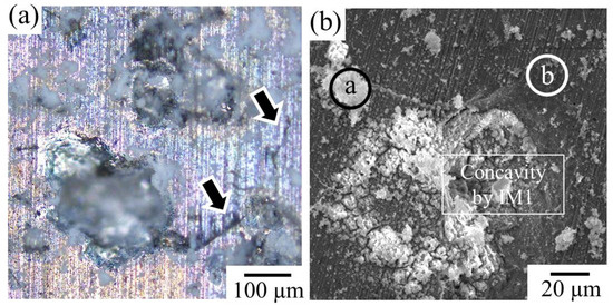
Figure 6.
(a) Surface morphology of the Sample F after immersed in Hanks’ solution for 250 h. The arrows indicate the formation of cracks around the dissolved IM1 phases. (b) Corresponding SEM image. At the points a and b indicated by white circles, SEM-EDS composition analyses were conducted.
Table 3.
SEM-EDS composition analysis result measured at positions a and b indicated in Figure 6b, in at.%.
The formation of such cracks is attributed to the rapid generation of hydrogen gas associated with dissolution. A schematic of the assumed crack formation mechanism is shown in Figure 7. Crack formation is considered to occur through the following processes:
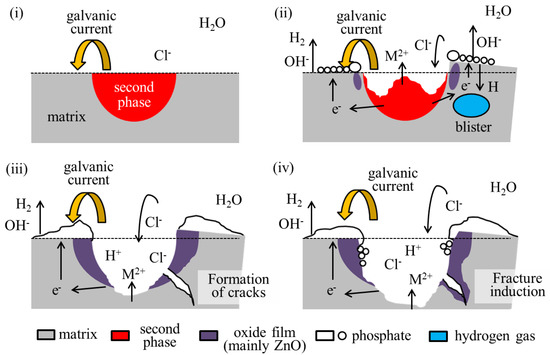
Figure 7.
A schematic diagram of the assumed crack formation process in the IM3/IM1 dual-phase alloy. The formation scheme is explained in the order of images (i–iv). Please see the manuscript for details.
- (i)
- Galvanic corrosion selectively causes anodic dissolution in the second phase, which is accompanied by active hydrogen evolution as a cathodic reaction in the nearby matrix phase, primarily by the following reactions.
Anodic reaction
Mg(s) = Mg2+(aq) + 2e−
Ca(s) = Ca2+(aq) + 2e−
Zn(s) = Zn2+(aq) + 2e−
Cathodic reaction
2H2O(aq) + 2e− = H2 (g) + 2OH− (aq)
Mg2+(aq) + OH− (aq) = Mg(OH)2 (s)
Mg(OH)2 (s) + 2Cl− (aq) = MgCl2 (aq) + 2OH− (aq)
Zn2+(aq) + 2OH− (aq) = Zn(OH)2 (s)
Zn(OH)2 (s) = ZnO (s) + H2O (aq)
- (ii)
- Some hydrogen atoms penetrate the matrix phase and rejoin on a molecular level below the surface. This generates hydrogen gas within the matrix phase and produces a swelling called a blister [38].
- (iii)
- At some point, the blisters rupture, causing cracks.
- (iv)
- The cracks may induce fracture of the alloy.
Therefore, it is considered that crack formation around the concavity was caused by the rapid dissolution of the second phase. Further control of the dissolution behavior is thus necessary to prevent the cracks’ formation caused by the formation of hydrogen gas blisters to achieve sound dynamic porosity on the surface of the dual-phase alloy.
3.2. Variation in Galvanic Corrosion Behavior between IM3 and IM1 Phases Depending on IM1 Phase Composition and Area Fraction
To obtain a control guideline for the IM3/IM1 dual-phase alloy, the galvanic currents between IM3/IM1 were performed. It has been reported that the galvanic current produced by dissimilar metal contacts between a less noble metal A and a noble metal C can be estimated by the following theoretical equation [39], under the condition that the galvanic potential of the electrically coupled metals A and C is in the region where the only significant reaction involving metal A is the anodic (metal dissolution) process, and the only significant reaction involving metal C is cathodic reduction:
where the superscripts A and C refer to metals A and C, respectively; Ig is the galvanic current, Εg is the galvanic potential, is the anodic current, and is the cathodic current. and are the corrosion potentials of the uncoupled metals, and are the corrosion current densities of the uncoupled metals. is the Tafel slope for the cathodic reaction involving metal C, is the Tafel slope for the anodic reaction involving metal A, and and
are the surface areas.
Based on this theoretical relationship, we attempted to experimentally examine the effects of the corrosion potential difference between the IM3/IM1 and their volume (area) fractions on the degradation behavior. Single-phase alloys composed of the IM1 and IM3 phases were prepared as the anode and cathode, respectively, for galvanic current measurement. As shown in Figure 3, the IM1 phase has a wide composition range in which the Mg/Zn ratio can be changed while maintaining the Ca composition. A previous study demonstrated that the corrosion potential of IM1 varied widely depending on the Mg/Zn ratio [10]. As the Mg/Zn ratio increases, the corrosion potential decreases continuously. Based on the results, two IM1 single-phase alloys with compositions of Ca3Mg7Zn8 (Mg/Zn ratio: 0.88) and Ca3Mg4.6Zn10.4 (Mg/Zn ratio: 0.44) were prepared.
The typical examples of the measured results are shown in the Supplementary Figure S1. After the initial transient region, the current density showed a stable value at around 6000–8000 s. Figure 8a,b shows the average galvanic current densities at the stable region measured in the several times of tests for the two IM1 anodes with different compositions with respect to the IM3 cathode. The results demonstrate that the galvanic current density increases as the Mg/Zn ratio in IM1 increases, i.e., as the corrosion potential difference with respect to IM3 increases, as expected. The measured current densities are in relatively good agreement with the values estimated by Equation (10) using the values evaluated from the polarization curves of the used anodic IM3 and cathodic IM1 samples shown in Supplementary Figure S2. Furthermore, the galvanic current density increased with an increase in the cathode/anode area fraction ratio, also showing relatively good agreement with the theoretical values, even in the present alloy systems that exhibited relatively severe dissolution behavior. The results indicate that the degradation rate in the IM3/IM1 dual-phase alloy can be controlled by varying the area (volume) fraction of the IM3/IM1 phases and the corrosion potential difference, which can be controlled by the composition of the equilibrium IM1 phase.
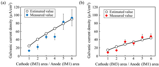
Figure 8.
Relationship between galvanic current density and area fraction of cathodic IM1 phase electrode with respect to anodic IM3 phase. (a) IM1 with composition of Ca3Mg7Zn8 (Mg/Zn ratio: 0.88) and (b) IM1 with composition of Ca3Mg4.6Zn10.4 (Mg/Zn ratio: 0.44).
3.3. Actual Control of Degradation Behavior of IM3/IM1 Dual-Phase Alloys
Based on the results shown in Figure 8, we attempted to develop a strategy for controlling the dissolution behavior of the IM3/IM1 dual-phase alloys by focusing on two other alloys with different compositions (samples I and J). Sample I had a composition of Ca13Mg26Zn61. This was prepared to reduce the corrosion potential difference by changing the composition of the faster-dissolving second phase of IM1 from Ca3Mg7Zn8 (Mg/Zn ratio: 0.88) in Sample F to the more electrochemically noble Ca3Mg4.6Zn10.4 (Mg/Zn ratio: 0.44). The other sample J had a composition of Ca12Mg25Zn63. This was prepared to reduce the corrosion potential difference between the two phases using the same strategy as in sample I, while simultaneously reducing the volume fraction of the second phase.
Figure 9 shows the microstructures of the prepared IM3/IM1 alloys. Composition analysis results by SEM-EDS are shown in Supplementary Figure S3. The measured results confirmed the change in the composition of the IM1 phases with the change in the Mg/Zn ratio of 0.79 in Sample F to 0.40 in Sample I and 0.30 in Sample J, as expected. In addition, the volume fraction of the IM1 phase changed from 15.9% in Sample F to 5.4% in Sample J, whereas it remained almost constant at 16.4% in Sample I.
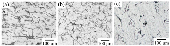
Figure 9.
Microstructures of three IM3/IM1 dual-phase alloys. (a) Sample F (Zn59Mg29Ca12), (b) Sample I (Zn61Mg26Ca13), and (c) Sample J (Zn63Mg25Ca12).
Figure 10 shows the variations in the surface morphology of each sample after four weeks of immersion in the Hanks’ solution. In Sample F, a significant uplift of the surface was observed due to blister formation, which caused the crack initiation, as shown in Figure 9a. However, such an uplift of the surface was significantly suppressed in samples I and J, where the second phase of IM1 changed to a more noble Ca3Mg4.6Zn10.4.

Figure 10.
LM images of the variations in the surface morphology of IM3/IM1 samples after immersion in Hanks’ solution for 4 weeks: (a) Sample F, (c) Sample I, and (e) Sample J. (b,d,f) Corresponding height contour map.
Figure 11 shows the cross-section SEM images of the immersed specimens. The observation was conducted by cutting the specimens after immersion. It was found that in addition to Sample F in which significant blister formation was observed, Sample J also partially showed traces of crack formation around the corroded areas. In specimens F and J, oxygen penetration was confirmed in the interior more than 200 µm depth from the surface (Figure 11c,i), but such behavior was seldom observed in Specimen I (Figure 11f). This suggests the oxidation occurred along the cracks in specimens F and J. That is, the reduction in the volume fraction of the second phase resulted in an increase in the dissolution rate, whereas when the volume fraction of the second phase is significantly decreased, it can cause blistering similar to that observed in sample F. On the contrary, while concavities in Sample I were formed by the selective dissolution of the second IM1 phase, excessive corrosion was suppressed by the formation of a zinc oxide film on the surface of the concavities. No cracks were observed in the matrix IM3 phase, indicating that the degradation behavior relatively close to the ideal situation shown in Figure 1 could be realized in the IM3/IM1 dual-phase alloy. In future work, we will further examine the effect of each factor on dissolution behavior during long-term immersion, assuming its use in vivo. Furthermore, it is necessary to specifically evaluate changes in mechanical properties due to microstructural control. As another topic, further control of the microstructure, especially focusing on the size, distribution, and morphology of constituent phases via the control of solidification conditions must be also considered.
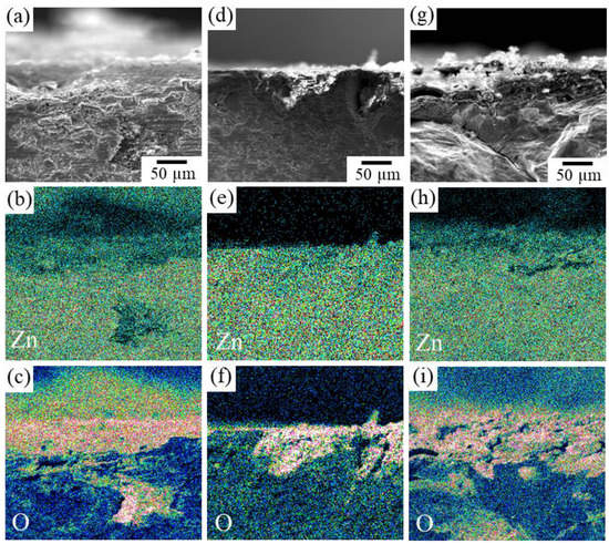
Figure 11.
SEM-EDS elemental mapping images of the cross-section of IM3/IM1 samples immersed in Hanks’ solution for 4 weeks: (a–c) Sample F, (d–f) Sample I, and (g–i) Sample J. (a,d,g) SEM image, (b,e,h) Zn concentration map, and (c,f,i) O concentration map.
4. Conclusions
As a new potential in-vivo biodegradable material that dynamically forms cell-inducing surface undulations as the dissolution progresses, a relatively ideal microstructure was obtained for the IM3/IM1 dual-phase alloy. These results suggest that the selective corrosion of the second phase may lead to the formation of a porous microstructure on the surface. A tendency for localized corrosion to be accelerated by an increase in the corrosion potential difference between the constituent phases or a decrease in the volume fraction of the second phase was observed. This indicates the possibility of controlling the dissolution behavior of dual-phase alloys through a more precise control of these factors in the future.
Supplementary Materials
The following supporting information can be downloaded at: https://www.mdpi.com/article/10.3390/met13061095/s1, Figure S1: Typical variations in current densities measured between the anodic IM3-Ca2Mg5Zn13 phase and cathodic IM1 phase with composition of Ca3Mg7Zn8 and (b) Ca3Mg4.6Zn10.4, depending on the area fraction of cathodic IM1 phase electrode with respect to anodic IM3 phase; Figure S2: The polarization curves of the IM3-Ca2Mg5Zn13, IM1-Ca3Mg7Zn8 and IM1-Ca3Mg4.6Zn10.4 phases, used for the evaluation of the galvanic current density shown in Supplementary Figure S1; Figure S3: (a,b) SEM images showing the microstructures in the prepared alloys: (a) Sample I and (b) Sample J. (c) Compositions in at.% examined by SEM-EDS at the points indicated in (a,b) and the expected constituent phases in the alloys; Table S1: Composition of the Hanks’ balanced salt solution used in this study (Gibco, US, No.14025).
Author Contributions
Conceptualization, K.H.; methodology, K.H.; investigation, S.S.; formal analysis, K.H., S.S. and T.T.; writing—original draft preparation, K.H.; writing—review and editing, T.T. and T.N.; funding acquisition, K.H. and T.N. All authors have read and agreed to the published version of the manuscript.
Funding
This work was supported by Grant-in-Aid for Scientific Research (B) with grant number: 15H04146 from Japan Society for the Promotion of Science (JSPS), and also supported by Japan Science and Technology Agency (JST), CREST (grant number JPMJCR2194), Japan.
Data Availability Statement
The key data are presented in the manuscript; Further data are not publicly available due to an ongoing study.
Conflicts of Interest
The authors declare no conflict of interest.
References
- Niinomi, M. Recent metallic materials for biomedical applications. Metall. Mater. Trans. A 2002, 33, 477–486. [Google Scholar] [CrossRef]
- Liu, Y.; Zheng, Y.; Chen, X.-H.; Yang, J.-A.; Pan, H.; Chen, D.; Wang, L.; Zhang, J.; Zhu, D.; Wu, S.; et al. Fundamental theory of biodegradable metals—Definition, criteria, and design. Adv. Func. Mater. 2019, 29, 1805402. [Google Scholar] [CrossRef]
- Witte, F.; Fischer, J.; Nellesen, J.; Crostack, H.A.; Kaese, V.; Pisch, A.; Beckmann, F.; Windhagen, H. In vitro and in vivo corrosion measurements of magnesium alloys. Biomaterials 2006, 27, 1013–1018. [Google Scholar] [CrossRef] [PubMed]
- Staiger, M.P.; Pietak, A.M.; Huadmai, J.; Dias, G. Magnesium and its alloys as orthopedic biomaterials: A review. Biomaterials 2006, 27, 1728–1734. [Google Scholar] [CrossRef] [PubMed]
- Kannan, M.B.; Raman, R.K.S. In vitro degradation and mechanical integrity of calcium-containing magnesium alloys in modified-simulated body fluid. Biomaterials 2008, 29, 2306–2314. [Google Scholar] [CrossRef]
- Gu, X.; Zheng, Y.; Cheng, Y.; Zhong, S.; Xi, T. In vitro corrosion and biocompatibility of binary magnesium alloys. Biomaterials 2009, 30, 484–498. [Google Scholar] [CrossRef] [PubMed]
- Zhang, S.; Zhang, X.; Zhao, C.; Li, J.; Song, Y.; Xie, C.; Tao, H.; Zhang, Y.; He, Y.; Jiang, Y.; et al. Research on an Mg-Zn alloy as a degradable biomaterial. Acta Biomater. 2010, 6, 626–640. [Google Scholar] [CrossRef] [PubMed]
- Zhen, Z.; Xi, T.-F.; Zheng, Y.-F. A review on in vitro corrosion performance test of biodegradable metallic materials. Trans. Nonferr. Met. Soc. China 2013, 23, 2283–2293. [Google Scholar] [CrossRef]
- Hagihara, K.; Ohkubo, M.; Yamasaki, M.; Nakano, T. Crystal-orientation-dependent corrosion behaviour of single crystals of a pure Mg and Mg-Al and Mg-Cu solid solutions. Corr. Sci. 2016, 109, 68–85. [Google Scholar] [CrossRef]
- Shuai, C.; Li, S.; Peng, S.; Feng, P.; Lai, Y.; Gao, C. Biodegradable metallic bone implants. Mater. Chem. Front. 2019, 3, 544–562. [Google Scholar] [CrossRef]
- Han, H.-S.; Jun, I.; Seok, H.-K.; Lee, K.-S.; Lee, K.; Witte, F.; Mantovani, D.; Kim, Y.-C.; Glyn-Jones, S.; Edwards, J.R. Biodegradable magnesium alloys promote angio-osteogenesis to enhance bone repair. Adv. Sci. 2020, 7, 200800. [Google Scholar] [CrossRef]
- Tsakiris, V.; Tardei, C.; Clicinschi, F.M. Biodegradable Mg alloys for orthopedic implants—A review. J. Mag. Alloys 2021, 9, 1884–1905. [Google Scholar] [CrossRef]
- Zberg, B.; Uggowitzer, P.J.; Löffler, L.F. MgZnCa glasses without clinically observable hydrogen evolution for biodegradable implants. Nat. Mater. 2009, 8, 887–891. [Google Scholar] [CrossRef] [PubMed]
- Hagihara, K.; Shakudo, S.; Fujii, K.; Nakano, T. Degradation behavior of Ca-Mg-Zn intermetallic compounds for use as biodegradable implant materials. Mater. Sci. Eng. C 2014, 44, 285–292. [Google Scholar] [CrossRef] [PubMed]
- Cao, J.D.; Weber, T.; Schäublin, R.; Löffler, J.F. Equilibrium ternary intermetallic phase in the Mg-Zn-Ca system. J. Mater. Res. 2016, 31, 2147–2155. [Google Scholar] [CrossRef]
- Lin, G.; Liu, D.; Chen, M.; You, C.; Li, Z.; Wang, Y.; Li, W. Preparation and characterization of biodegradable Mg-Zn-Ca/MgO nanocomposites for biomedical applications. Mater. Charact. 2018, 144, 120–130. [Google Scholar] [CrossRef]
- Babilas, R.; Bajorek, A.; Włodarczyk, P.; Łoński, W.; Szyba, D.; Babilas, D. Effect of Au addition on the corrosion activity of Ca-Mg-Zn bulk metallic glasses in Ringer’s solution. Mater. Chem. Phys. 2019, 226, 51–58. [Google Scholar] [CrossRef]
- Schäublin, R.E.; Becker, M.; Cihova, M.; Gerstl, S.S.A.; Deiana, D.; Hébert, C.; Pogatscher, S.; Uggowitzer, P.J.; Löffler, J.F. Precipitation in lean Mg-Zn-Ca alloys. Acta Mater. 2022, 239, 118223. [Google Scholar] [CrossRef]
- Wang, Y.; Zhang, L.; Chen, B.; Bo, W.; Zhou, Y.; Geng, G. Effect of Zn on glass-forming capacity and corrosion resistance of Ca-based amorphous alloys. J. Non-Cryst. Solids 2022, 591, 121713. [Google Scholar] [CrossRef]
- Fu, J.; Du, W.; Liu, K.; Du, X.; Zhao, C.; Liang, H.; Mansoor, A.; Li, S.; Wang, Z. Effect of the Ca2Mg6Zn3 phase on the corrosion behavior of biodegradable Mg-4.0Zn-0.2Mn-xCa alloys in Hank’s solution. Materials 2022, 15, 2079. [Google Scholar] [CrossRef]
- Szyba, D.; Bajorek, A.; Babilas, D.; Temleitner, L.; Łukowiec, D.; Babilas, R. New resorbable Ca-Mg-Zn-Yb-B-Au alloys: Structural and corrosion resistance characterization. Mater. Des. 2022, 213, 110327. [Google Scholar] [CrossRef]
- Jin, C.; Liu, Z.; Yu, W.; Qin, C.; Yu, H.; Wang, Z. Biodegradable Mg-Zn-Ca-based metallic glasses. Materials 2022, 15, 2172. [Google Scholar] [CrossRef] [PubMed]
- Cai, Z.; Chen, J.; Xie, G. Mechanical properties and corrosion resistance of large-size biodegradable Ca-Mg-Zn bulk metallic glasses fabricated via powder metallurgy. Intermetallics 2022, 148, 107633. [Google Scholar] [CrossRef]
- Li, Z.H.; Sasaki, T.T.; Uedono, A.; Hono, K. Role of Zn on the rapid age-hardening in Mg-Ca-Zn alloys. Scr. Mater. 2022, 216, 114735. [Google Scholar] [CrossRef]
- Li, K.; Zhou, S.; Bao, W.; Chen, J.; Li, J.; Xie, G. New biodegradable Mg-Zn-Ca bulk metallic glass composite with large plasticity reinforced by SnZn alloy. Mater. Sci. Eng. A 2023, 873, 145045. [Google Scholar] [CrossRef]
- Tapiero, H.; Tew, K.D. Trace elements in human physiology and pathology: Zinc and metallothioneins. Biomed. Pharm. 2003, 57, 399–411. [Google Scholar] [CrossRef]
- Nakano, T.; Matsumoto, K.; Seno, T.; Oma, K.; Umakoshi, Y. Effect of chemical ordering on the deformation mode of Al-rich Ti-Al single crystals. Philos. Mag. A 1996, 74, 251–268. [Google Scholar] [CrossRef]
- Nakano, T.; Hagihara, K.; Seno, T.; Sumida, N.; Yamamoto, M.; Umakoshi, Y. Stress anomaly in Al-rich Ti-Al single crystals deformed by the motion of 1/2 < 110] ordinary dislocations. Philos. Mag. Lett. 1998, 78, 385–391. [Google Scholar]
- Nakano, T.; Azuma, M.; Umakoshi, Y. Microstructure and high-temperature strength in MoSi2/NbSi2 duplex silicides. Intermetallics 1998, 6, 715–722. [Google Scholar] [CrossRef]
- Hagihara, K.; Tanaka, T.; Nakano, T.; Umakoshi, Y. Plastic deformation behavior of Ni3(Ti0.90Nb0.10) single crystals with the nine-layered ordered rhombohedral structure. Acta Mater. 2005, 53, 5051–5059. [Google Scholar] [CrossRef]
- Hagihara, K.; Nakano, T. Fracture behavior and toughness of NbSi2-based single crystals and MoSi2(C11b)/NbSi2(C40) duplex crystals with a single set of lamellae. Acta Mater. 2011, 59, 4168–4176. [Google Scholar] [CrossRef]
- Hagihara, K.; Fukusumi, Y.; Yamasaki, M.; Nakano, T.; Kawamura, Y. Non-basal slip systems operative in Mg12ZnY long-period stacking ordered (LPSO) phase with 18R and 14H structures. Mater. Trans. 2013, 54, 693–697. [Google Scholar] [CrossRef]
- Hagihara, K.; Fujii, K.; Matsugaki, A.; Nakano, T. Possibility of Mg- and Ca-based intermetallic compounds as new biodegradable implant materials. Mater. Sci. Eng. C 2013, 33, 4101–4111. [Google Scholar] [CrossRef] [PubMed]
- ASTM G31-72; Standard Practice for Laboratory Immersion Corrosion Testing of Metals. ASTM: West Conshohocken, PA, USA, 1997.
- ASTM G71-81; Standard Guide for Conducting and Evaluating Galvanic Corrosion Tests in Electrolytes. ASTM: West Conshohocken, PA, USA, 2003.
- Zhang, Y.N.; Kevorkov, D.; Bridier, F.; Medraj, M. Experimental study of the Ca-Mg-Zn system using diffusion couples and key alloys. Sci. Technol. Adv. Mater. 2011, 12, 025003. [Google Scholar] [CrossRef] [PubMed]
- Zhang, Y.N.; Kevorkov, D.; Li, J.; Essadiqi, E.; Medraj, M. Determination of the solubility range and crystal structure of the Mg-rich ternary compound in the Ca-Mg-Zn system. Intermetallics 2010, 18, 2404–2411. [Google Scholar] [CrossRef]
- Chen, J.; Ai, M.; Wang, J.; Han, E.-H.; Ke, W. Formation of hydrogen blister on AZ91 magnesium alloy during cathodic charging. Corr. Sci. 2009, 51, 1197–1200. [Google Scholar] [CrossRef]
- Mansfeld, F. Area relationships in galvanic corrosion. Corrosion 1971, 27, 436–442. [Google Scholar] [CrossRef]


Disclaimer/Publisher’s Note: The statements, opinions and data contained in all publications are solely those of the individual author(s) and contributor(s) and not of MDPI and/or the editor(s). MDPI and/or the editor(s) disclaim responsibility for any injury to people or property resulting from any ideas, methods, instructions or products referred to in the content. |
© 2023 by the authors. Licensee MDPI, Basel, Switzerland. This article is an open access article distributed under the terms and conditions of the Creative Commons Attribution (CC BY) license (https://creativecommons.org/licenses/by/4.0/).