
Influences of Anisotropic Equivalent Field and Magnetic Damping Coefficient on Giant Magnetoimpedance Effect of Cylindrical Alloy Fibers: Theoretical Magnetoimpedance Calculations


 ,
, 
Abstract
:1. Introduction
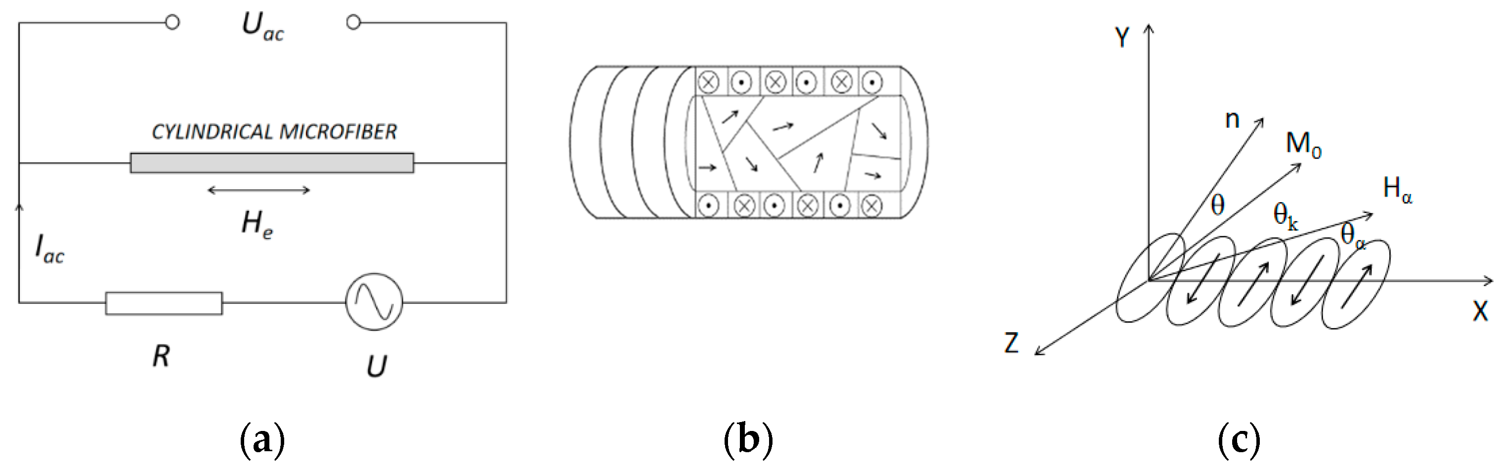
2. GMI Model of Cylindrical Microfiber
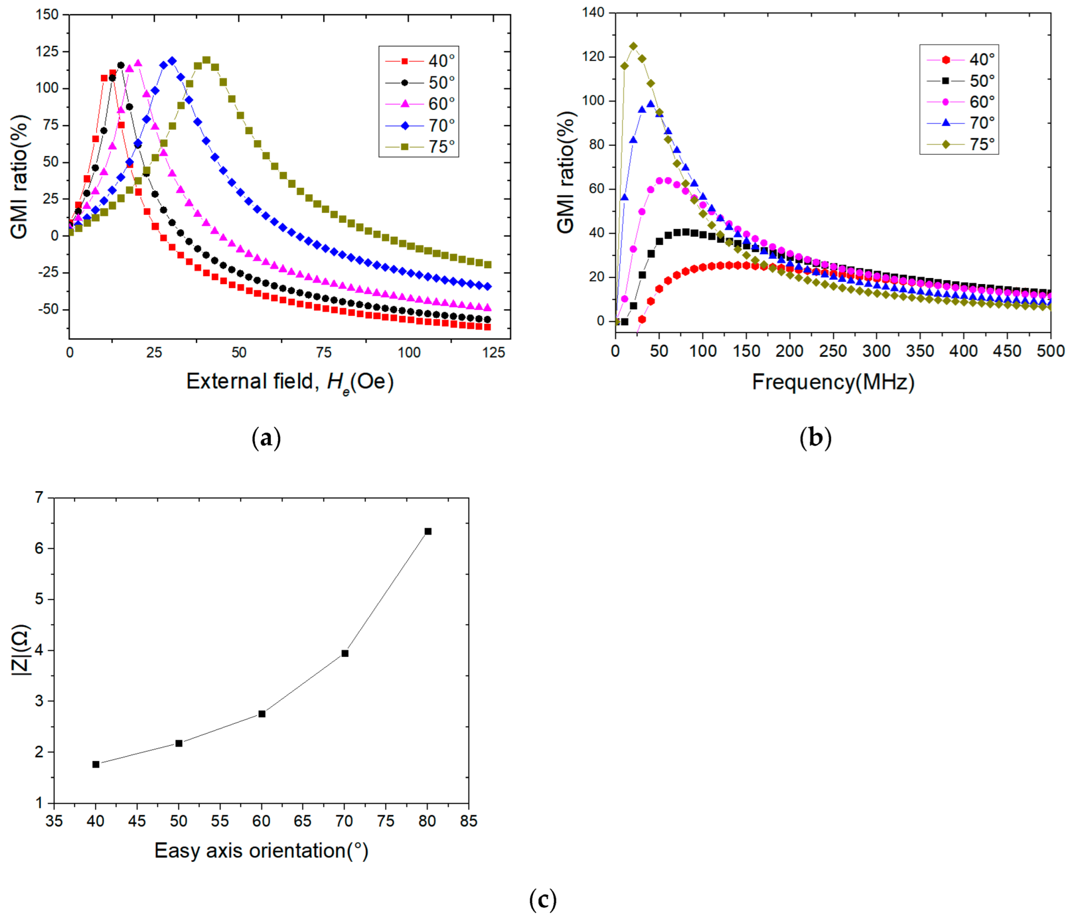
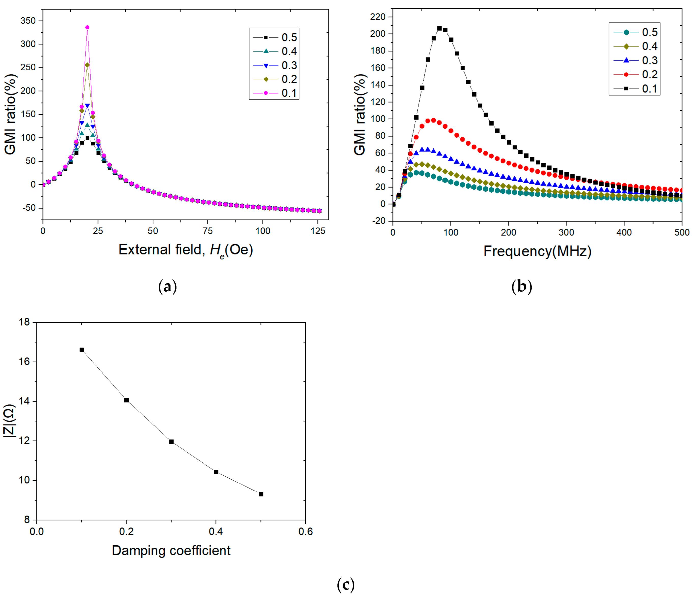
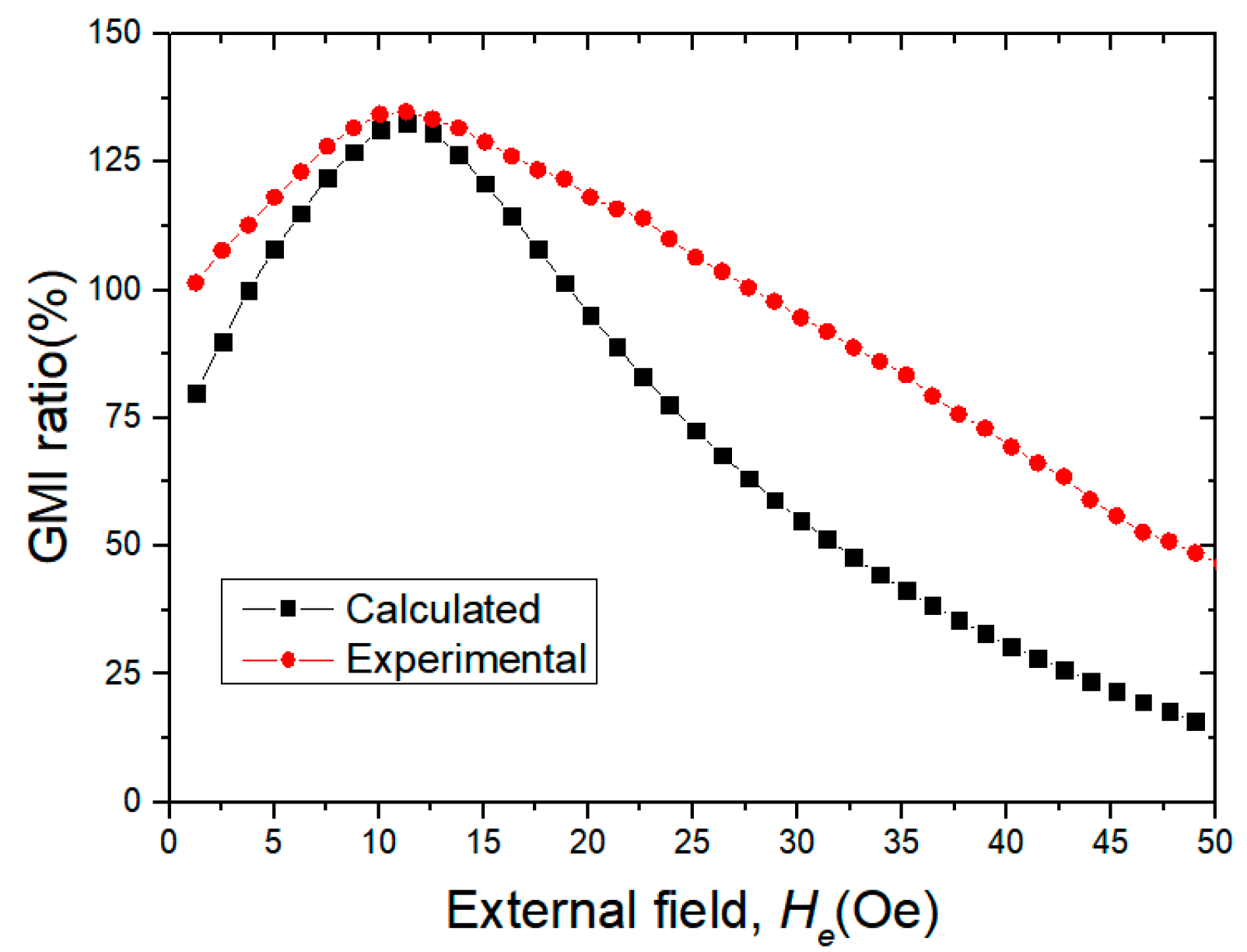
3. Results and Discussion
4. Conclusions
Author Contributions
Funding
Institutional Review Board Statement
Informed Consent Statement
Data Availability Statement
Conflicts of Interest
References
- Garcia, D.; Raposo, V.; Montero, O.; Iniguez, J.I. Influence of magnetostriction constant on magnetoimpedance–frequency dependence. Sens. Actuators A Phys. 2006, 129, 227–230. [Google Scholar] [CrossRef]
- Qin, F.X.; Peng, H.X.; Popov, V.V.; Panina, L.V.; Ipatov, M.; Zhukova, V.; Zhukov, A.; Gonzalez, J. Stress tunable properties of ferromagnetic microwires and their multifunctional composites. J. Appl. Phys. 2011, 109, 07A310. [Google Scholar] [CrossRef]
- Liu, J.; Pang, M.; Cao, G.; Qu, G.; Wang, X.; Zhang, Y.; Liu, R.; Shen, H. Comparative study of tensile properties and magnetic properties for Nb-doped Fe-based wires. J. Mater. Res. Technol. 2020, 9, 12907–12916. [Google Scholar] [CrossRef]
- Namiki, A.; Yokosawa, S. Origami folding by multifingered hands with motion primitives. Cyborg Bionic Syst. 2021, 2021, 9851834. [Google Scholar] [CrossRef]
- Liu, J.; Qin, F.; Chen, D.; Shen, H.; Wang, H.; Xing, D.; Phan, M.-H.; Sun, J. Combined current-modulation annealing induced enhancement of giant magnetoimpedance effect of Co-rich amorphous microwires. J. Appl. Phys. 2014, 115, 17A326. [Google Scholar] [CrossRef]
- Jiang, S.; Wang, H.; Estevez, D.; Huang, Y.; Zhang, L.; Shen, H.; Ning, Z.; Qin, F.; Sun, J. Surface microstructural design to improve mechanical and giant magneto-impedance properties of melt-extracted CoFe-based amorphous wires. Mater. Des. 2021, 204, 109642. [Google Scholar]
- Wang, H.; Kan, J.; Zhang, X.; Gu, C.; Yang, Z. Pt/CNT micro-nanorobots driven by glucose catalytic decomposition. Cyborg Bionic Syst. 2021, 2021, 9876064. [Google Scholar] [CrossRef]
- Panina, L.; Mohri, K.; Uchiyama, T.; Noda, M.; Bushida, K. Giant magneto-impedance in Co-rich amorphous wires and films. IEEE Trans. Magn. 1995, 31, 1249–1260. [Google Scholar] [CrossRef]
- Velleuer, J.; Munoz, A.G.; Yakabchuk, H.; Schiefer, C.; Hackl, A.; Kisker, E. Giant magneto impedance in electroplated NiFeMo/Cu microwires. J. Magn. Magn. Mater. 2007, 311, 651–657. [Google Scholar] [CrossRef]
- Wang, H.; Qin, F.X.; Xing, D.W.; Cao, F.Y.; Wang, X.D.; Peng, H.X.; Sun, J.F. Relating residual stress and microstructure to mechanical and giant magneto-impedance properties in cold-drawn Co-based amorphous microwires. Acta Mater. 2012, 60, 5425–5436. [Google Scholar] [CrossRef]
- Ipatov, M.; Chizhik, A.; Zhukova, V.; Gonzalez, J.; Zhukov, A. Correlation of surface domain structure and magneto-impedance in amorphous microwires. J. Appl. Phys. 2011, 109, 113924. [Google Scholar] [CrossRef]
- Zhang, S.L.; Sun, J.F.; Xing, D.W.; Qin, F.X.; Peng, H.X. Large GMI effect in Co-rich amorphous wire by tensile stress. J. Magn. Magn. Mater. 2011, 323, 3018–3021. [Google Scholar] [CrossRef]
- Qin, F.; Peng, H.X. Ferromagnetic microwires enabled multifunctional composite materials. Prog. Mater. Sci. 2013, 58, 183–259. [Google Scholar] [CrossRef]
- Le, A.T.; Cho, W.S.; Lee, H.; Vázquez, M.; Kim, C.O. Giant magnetoimpedance effect in a glass-coated microwire LC-resonator for high-frequency sensitive magnetic sensor applications. J. Alloys Compd. 2007, 443, 32–36. [Google Scholar] [CrossRef]
- Phan, M.H.; Peng, H.X. Giant magnetoimpedance materials: Fundamentals and applications. Prog. Mater. Sci. 2008, 53, 323–420. [Google Scholar]
- Ma, L.; Zhao, C.; Ji, W.; Liu, Q.; Wang, J. Giant magneto-impedance effect adjusted by electrolytic polishing and thinning of Co-based amorphous ribbons. J. Phys. D Appl. Phys. 2022, 55, 34. [Google Scholar] [CrossRef]
- Zhukov, A.; Ipatov, M.; Corte-León, P.; Gonzalez-Legarreta, L.; Blanco, J.M.; Zhukova, V. Soft magnetic microwires for sensor applications. J. Magn. Magn. Mater. 2020, 498, 166180. [Google Scholar] [CrossRef]
- García, K.L.; Valenzuela, R. Correlation between magnetization processes and giant magnetoimpedance response in CoFeBSi amorphous CoFeBSi wires. J. Non-Cryst. Solids 2001, 287, 313–317. [Google Scholar] [CrossRef]
- Zhao, Y.; Hao, H.; Zhang, Y. Preparation and giant magneto-impedance behavior of Co-based amorphous wires. Intermetallics 2013, 42, 62–67. [Google Scholar] [CrossRef]

Publisher’s Note: MDPI stays neutral with regard to jurisdictional claims in published maps and institutional affiliations. |
© 2022 by the authors. Licensee MDPI, Basel, Switzerland. This article is an open access article distributed under the terms and conditions of the Creative Commons Attribution (CC BY) license (https://creativecommons.org/licenses/by/4.0/).
Share and Cite
Wang, T.; Zhang, Y.; Lei, J.; Wang, Q.; Chen, J.; Li, H.; Wu, Z.; Cui, Z.; Liu, M.; Rao, J. Influences of Anisotropic Equivalent Field and Magnetic Damping Coefficient on Giant Magnetoimpedance Effect of Cylindrical Alloy Fibers: Theoretical Magnetoimpedance Calculations. Metals 2022, 12, 1532. https://doi.org/10.3390/met12091532
Wang T, Zhang Y, Lei J, Wang Q, Chen J, Li H, Wu Z, Cui Z, Liu M, Rao J. Influences of Anisotropic Equivalent Field and Magnetic Damping Coefficient on Giant Magnetoimpedance Effect of Cylindrical Alloy Fibers: Theoretical Magnetoimpedance Calculations. Metals. 2022; 12(9):1532. https://doi.org/10.3390/met12091532
Chicago/Turabian StyleWang, Tao, Yingjie Zhang, Jingtao Lei, Qiuyuan Wang, Jinbo Chen, Hengyu Li, Zhizheng Wu, Ze Cui, Mei Liu, and Jinjun Rao. 2022. "Influences of Anisotropic Equivalent Field and Magnetic Damping Coefficient on Giant Magnetoimpedance Effect of Cylindrical Alloy Fibers: Theoretical Magnetoimpedance Calculations" Metals 12, no. 9: 1532. https://doi.org/10.3390/met12091532
APA StyleWang, T., Zhang, Y., Lei, J., Wang, Q., Chen, J., Li, H., Wu, Z., Cui, Z., Liu, M., & Rao, J. (2022). Influences of Anisotropic Equivalent Field and Magnetic Damping Coefficient on Giant Magnetoimpedance Effect of Cylindrical Alloy Fibers: Theoretical Magnetoimpedance Calculations. Metals, 12(9), 1532. https://doi.org/10.3390/met12091532