Abstract
With the rapid development of low-carbon high strength steel, higher requirements are put forward for the matching welding consumables. The deposited metals with 0.62–2.32% Cu addition was prepared by tungsten inert gas welding via metal cored wire. The effect of Cu element on microstructure and mechanical properties of deposited metals were investigated. The multiphase microstructure of deposited metals consists of bainite, martensite, residual austenite, and martensite-austenite constituents. It is found that Cu decreases the start temperature of martensite (Ms) and enlarges the temperature range of bainite from 372 K to 416 K, improving the formation of bainite. With the increase of Cu content, the fraction of martensite decreases and the shape of M-A constituents changes from strip into granular. There are BCC and FCC Cu precipitates in deposited metals. The diameter of Cu precipitates is 14–28 nm, and the volume fraction of it increases with the increase of Cu content. Meanwhile, the deposited metals with 1.79% Cu can achieve a 10% enhancement in strength (yield strength, 873–961 MPa, ultimate tensile strength, 1173–1286 MPa) at little expense of impact toughness (64.56–56.39 J at −20 °C). Cu precipitation can effectively improve the strength of the deposited metals, but it degrades toughness because of lower crack initiation energy. The deposited metal with 1.79% Cu addition shows an excellent strength-toughness balance.
1. Introduction
For the widely use of low-carbon high strength steels in engineering applications, the matching welding consumables are critically needed. The novel welding consumables are required with high strength, satisfactory toughness, good fabricability, and reduced the carbon dioxide emission. Increasing the use of high strength steel by 35% could easily reduce carbon emissions by at least 70% [1]. In recent years, the metal cored wire has been paid more attention and rapid development, which have many advantages [2,3], such as high welding efficiency and good weldability. Furtherly, the chemical composition of wires can be easily adjusted on the basis of engineering requirements. Although carbon is an economical and practical strengthener, the addition of much carbon will reduce the weldability of metal cored wire [4]. Thus, the metal cored wire should contain low level (<0.1 wt%) carbon [5,6,7]. Moreover, this metal cored wires are relatively cheaper than the traditional solid wire. All these attractive properties allow the metal cored wire have broad application prospects.
The mechanical properties of materials strongly depend on the microstructural features. To acquire the deposited metals with good strength and satisfactory toughness, the suitable microstructure is multiphase consisted of bainite, martensite and residual austenite (RA) [8,9,10,11]. Among them, the bainite and RA was designed to improve the toughness, and martensite was used to maintain high strength of deposited metals. Compared with martensite, bainite and RA are soft phase, which can coordinate stress during deformation and effectively improve toughness. The RA also can improve toughness of materials through transformation-induced plasticity (TRIP) effect [12]. Martensite usually exists as massive martensite and martensite-austenite(M-A) constituents due to incompletion of bainite transformation, which is considered to be detrimental to toughness [13].
In order to develop high strength welding consumables, researchers started to borrow the idea from the nano-structured steels with nanoscale Cu precipitation [14,15,16,17]. The precipitation of Cu-rich nanoscale precipitates is very attractive, which can obtain a greatly high strengthening response via precipitating on nanoscale. For example, the high strength low alloy (HSLA-100) steels can easily achieve the high yield strength (~700 MPa) [18]. Mattes et.al [19] reported that the yield strength of specimen increases by ~248 MPa with increase of 1 wt% Cu via precipitation hardening. And the Cu-precipitates also can reduce the mobility of dislocations [20]. The low-carbon nanostructured steel can successfully gain 1460 MPa of the Cu and NiAl coprecipitation with approving ductility by Jiao [5]. There are some studies on Cu precipitation of welding metals. The Cu element could reduce the start temperature of martensite (Ms), enlarging the transformation interval of bainite. It was found the Cu precipitates can effectively improve strength without harm to toughness [21]. Wang [22] showed that nanoscale Cu precipitates in reheated areas of deposited metal, where the peak temperature is in 500–600 °C, satisfying the kinetics of Cu precipitation. Furtherly, weldability is also important issue during practical engineering application of welding consumables. The steel strengthened by Cu-rich precipitation have been proved to be welded easily. Chen [6] found that the nanostructured steels with the Cu/Mn additions show well weldability with good strength-ductility balance. The toughness of deposited metals with Cu-added show interesting behaviors. Dislocation would loop around the nondeformable precipitates, which is beneficial for toughness [23]. Wang [24] indicated that toughness of deposited metals degrades due to the transformation of Cu precipitates from body centred cube (BCC) structure into face centred cube (FCC). There are different points of effect of the Cu precipitates on the toughness of deposited metal. Further, the studies are mainly on the weldability of steels with Cu addition through thermal simulation experiment prepared by Gleeble instrument, but the actual welding process is a complex process that involves the type of welding materials, multiple thermal cycle and heat accumulation, these factors have significant effect on the form and quantity of Cu precipitation. Thus, the deposited metals with Cu addition are necessary to study, and the welding consumables with suitable Cu addition is an efficient solution for an advanced strength-toughness balance.
In this paper, the microstructure-mechanical properties relationships of deposited metals prepared by the metal cored wire via tungsten inert gas (TIG) welding are comprehensively studied. The influence of Cu addition on microstructure and mechanical properties was comprehensively explained through thermodynamic calculations and precipitation characteristic. Furtherly, the effect of Cu addition on strength and toughness is discussed, and the optimal amount of Cu addition will be determined to achieve strength-toughness balance of deposited metal. This research provides necessary theoretical basis for practical engineering application.
2. Materials and Methods
2.1. Materials
The metal-cored wire was designed by authors. The diameter of the wire is 1.2 mm and filling rate is about 15%. They are not seamless wires. The dimension of the steel sheath (99.6%) outside is 12 mm × 0.5 mm. The flux inside is metal particles. The formation process of wires included four steps: U-groove pressing formation, flux filling, rolling sealing and diameter reduction [25]. The multi-pass deposited metals were prepared by tungsten inert gas (TIG) welding process with 100% Ar shielding gas. The welding current and welding voltage were 190 A and 15–17 V, respectively. The travel speed kept in 280–300 mm/min. The inter-pass temperature was ~150 °C. The width and height of welding bead are ~7 mm and 6.25 mm. The height of each layer of deposited metals is ~1.88 mm. The total height of deposited metal is about 15 mm, ensuring that all samples are machined from deposited metal. The length of deposited metals is 300 mm (Figure 1). The chemical compositions of deposited metal measured by Optical Emission Spectrometer DF-100 are introduced in Table 1. The deposited metals are named as Cu 0.62, Cu 1.38, Cu 1.79 and Cu 2.32.
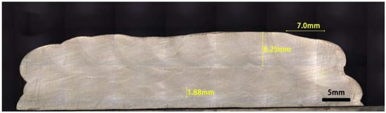
Figure 1.
Macroscopic structure of deposited metal.

Table 1.
Chemical composition of deposited metals (wt%).
2.2. Microstructure Observation
Scanning electron microscopy (SEM, JSM-7800F, JEOL, Shojima city, Tokyo, Japan), transmission electron microscopy (TEM, JEM-2100, JEOL, Shojima city, Tokyo, Japa), electron back-scattered diffraction (EBSD, EDAX-TSL, JEOL, Shojima city, Tokyo, Japa) and X-ray diffraction (XRD, D8 Advanced, Bruker, Bremen, Germany) were used to observe the microstructure of deposited metal. The specimens were polished through the standard mechanical grinding. Then chemical etching with 4 vol% nitric acid alcohol for 5 s was used to reveal microstructure for SEM observation. For TEM observation, disc specimens with ø3.0 mm were polished to 50 µm in thickness, then prepared by twinjet polishing with 5 vol% perchloric acid alcohol solution. The high resolution transmission electron microscopy (HRTEM) was used to examine crystal structure, morphology and diameter of nanoscale precipitates. The specimens for EBSD were electropolished 20 s with voltage of 30 V in 5 vol% perchloric acid alcohol solution. The deposited metals were also conducted by XRD with Cu-Kα (λ = 1.5406 A°) at a scanning rate of 0.02°/min. The volume fraction of residual austenite (RA) was calculated by Rietveld refinement method, which is integrated intensities of austenite peaks and ferrite peaks [26]. Then the fullwidth at half-maximum values (FWHM) with a modified Williamson–Hall (MWH) method were used to calculate the dislocation density of deposited metals [27].
As a supplement for the experimental results, thermodynamic calculations on phase transformation were performed with JMatPro software (7.0, Sente Software, Surrey, UK) based on general steel data base.
2.3. Mechanical Properties Testing
The tensile specimens were processed longitudinally from deposited metals. Tensile testing (thickness 3.0 mm × width 6.0 mm, gauge length of 25 mm) was tested on the electronic material testing machine (MTS Exceed E45, MTS Systems Co., Ltd, Eden Prairie, MN, USA). The deformation speed is about 0.5 mm/min. Three sets of samples were tested at room temperature to ensure the results. The Charpy-V impact specimens (10.0 mm ×10.0 mm ×55 mm) notched perpendicular to welding direction were tested by the JB-300B impact tester (JB-300B, SANS, Shenzhen, China) with the velocity of 5.2 m/s, according to ASTM E23. The testing temperature is −20 °C. The oscilloscope recorded the initiation energy, propagation energy and total absorbing energy of impact test. Before testing, the specimens were soaked in a tank at −20 °C for 20 min to guarantee a uniform temperature of the entire specimens. Anhydrous alcohol was used as the refrigerating medium. The time from taking out the specimen from the tank to completion of test was within 5 s.
3. Results
3.1. Microstructure Characterization
There is multiphase microstructure of deposited metals, consisting of bainite, martensite, martensite-austenite (M-A) constituents, and residual austenite (RA) (Figure 2 and Figure 3). The white lumps and granules dispersed in matrix are believed as massive martensite and M-A constituents. The microstructure of Cu 0.62 are bainite and massive martensite (Figure 2a). The shape of martensite changes from massive to banded of Cu 1.38 and Cu 1.79. The area fractions of martensite calculated via Image Pro software are reduced to 29.7% and 28.1%, which is about 32.2% of Cu 0.62. The martensite and M-A constituents are in shape of short rod of Cu 2.32. The area fraction of martensite and M-A constituents is total 27.2%. The volume fraction of residual austenite (RA) of deposited metals calculated by XRD are 4.01% (Cu 0.62), 6.18% (Cu 1.38), 11.12% (Cu 1.79), and 6.45% (Cu 2.32), respectively (Figure 3). The dislocation density of deposited metals is 2.18 × 10¹⁴ m−2 (Cu 0.62), 2.48 × 10¹⁴ m−2 (Cu 1.38), 2.24 × 10¹⁴ m−2 (Cu 1.79) and 5.10 × 10¹³ m−2 (Cu 2.32), respectively.
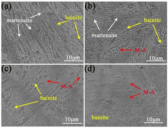
Figure 2.
Multiphase microstructure of deposited metals with different Cu addition. (a) Cu 0.62, (b) Cu 1.38, (c) Cu 1.79, (d) Cu 2.32.
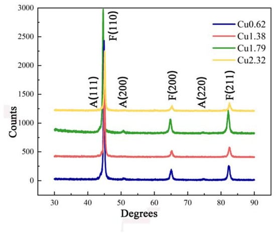
Figure 3.
XRD patterns of deposited metals with different Cu addition. A means γ-Fe, F means α-Fe.
From the crystallographic morphology observed by EBSD, the microstructure of deposited metals is lath structure (Figure 4a–d). The characteristics of the laths is anisotropic. The grain boundaries with 2–5°, 5–15°and 15–180° are represented as red, green and blue lines, respectively (Figure 4e–h). The high angle grain boundaries (>15°) are the boundaries of laths, and the small angle grain boundaries are within laths. The area fractions of high angle grain boundaries are 17.38% (Cu 0.62), 18.24% (Cu 1.38), 23.54% (Cu 1.79), and 19.60% (Cu 2.32), respectively (Figure 4i).
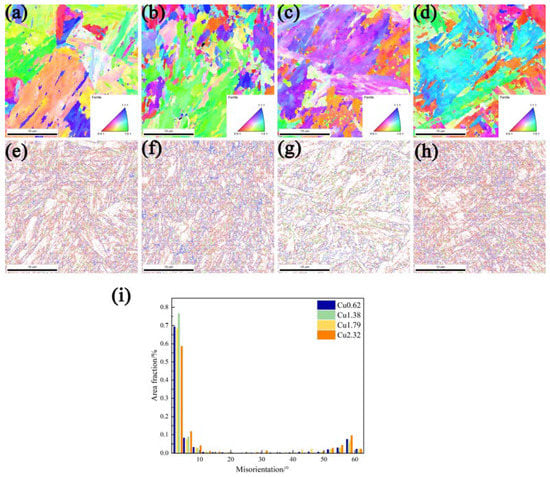
Figure 4.
EBSD IPF maps (a–d), misorientation angle maps (e–h), and area fraction of misorientation degree (i) of deposited metals. (a,e) Cu 0.62, (b,f) Cu 1.38, (c,g) Cu 1.79, (d,h) Cu 2.32.
The microstructure of deposited metals is also observed by TEM (Figure 5). The lath structure with the width >500 nm of Cu 0.62 is inhomogeneous. When Cu content increases, the characteristics of lath become clear and the width decrease from 500 nm to ~170 nm. Cu addition induces the formation of submicrometer-sized lath structure. The average width of lath structure in Cu 1.79 is ~170 nm, which is the minimum (Figure 5c). The RA (~100 to ~200 nm) exists as film between laths (Figure 6). The orientation relationship between RA and α-Fe matrix computed by selected area electron diffraction (SAED) is consistent with the Kurdjumov-Sachs (K-S) orientation [28]: [110] γ//[100] α and () γ//(011) α. With the increase of 0.62–1.79% Cu addition, the area fraction of RA increases and its distribution becomes dense. As for Cu 2.32, the area fraction of RA decreases.
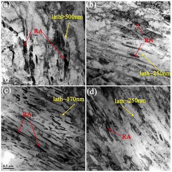
Figure 5.
TEM bright-field of deposited metals. (a) Cu 0.62, (b) Cu 1.38, (c) Cu 1.79, (d) Cu 2.32. The α-Fe of deposited metals is lath structure, the black film area is RA.
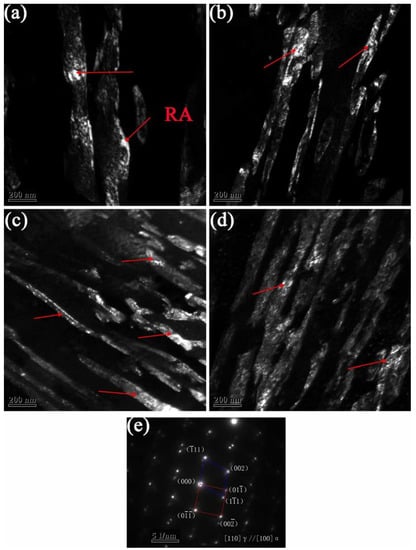
Figure 6.
TEM dark-field of RA in deposited metals. (a) Cu 0.62, (b) Cu 1.38, (c) Cu 1.79, (d) Cu 2.32, (e) SAED images of RA and matrix, meaning the relationship between them is the Kurdjumov-Sachs (K-S) orientation.
There are also Cu precipitates of deposited metals (Figure 7). The energy disperse spectroscopy (EDS) were performed on these ellipse precipitates and α-Fe marix. The components of α-Fe marix are C, Cr, Mn, Fe, and Ni. There is no Cu element detected in the matrix. According to chemical composition of deposited metals, the Cu precipitation will occur. Due to the nanoscale size of black precipitates, the chemical composition of particles will be deviated during EDS analysis. It can be seen from the results that the content of Cu increases significantly near precipitates, which were 6.54 wt% (Cu 0.62), 3.54 wt% (Cu 1.38), 5.05 wt% (Cu 1.79) and 11.94 wt% (Cu 2.32), respectively. So, the ellipse precipitates were identified as Cu precipitation. The volume fraction and diameter of Cu precipitates in deposited metals are listed in Table 2. The diameter of Cu precipitates in Cu 0.62 is only 14.21 nm. The diameter of Cu precipitates in Cu 1.38, Cu 1.79, and Cu 2.32 is ~28 nm, which is twice as large as that in Cu 0.62. The volume fraction of Cu precipitates increases obviously with increase of Cu addition.
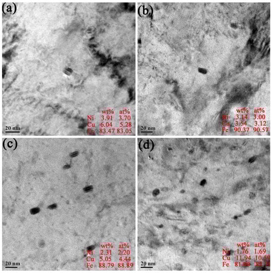
Figure 7.
TEM morphologies and components by EDS of Cu precipitates. (a) Cu 0.62, (b) Cu 1.38, (c) Cu 1.79, (d) Cu 2.32. The black ellipse precipitates are Cu precipitation.
Table 2.
Diameter and volume fraction of Cu precipitates.
3.2. Mechanical Properties
The engineering stress-strain curves of deposited metals are presented in Figure 8a. The average ultimate tensile strengths (UTS) of deposited metals are 1172 ± 12 MPa (Cu 0.62), 1199 ± 27 MPa (Cu 1.38), 1286 ± 24 MPa (Cu 1.79), and 1241 ± 3 MPa (Cu 2.32), respectively. And the average yield strengths (YS) are 873 ± 21 MPa (Cu 0.62), 899 ± 12 MPa (Cu 1.38), 961 ± 24 MPa (Cu 1.79), and 871 ± 15 MPa (Cu 2.32), respectively. The elongation of deposited metals decreases significantly from 15% to 9% with increase of Cu content. The tensile reduction area can reach over 40% of Cu 0.62, Cu 1.38 and Cu 1.79, indicating an excellent ductility. While the tensile reduction area decreased sharply to 14.1% of Cu 2.32.
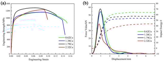
Figure 8.
Mechanical properties of deposited metals. (a) Engineering strength-strain curves. The Cu 1.79 obtains the maximum strength value. (b) The Charpy V-Notch impact load curves (solid lines) and impact energy curves (dotted lines).
The Charpy V-Notch impact load curves and impact energy curves of deposited metals showed that the total impact energy (Et) was 64.56 ± 3.11 J, 52.56 ± 2.08 J, 56.39 ± 1.75 J, 42.66 ± 1.48 J, respectively (Figure 8b). The crack initiation energy (Ei) was obtained by integrating the force-displacement curves between the displacement range from 0 to maximum force value, the remaining area is the crack propagation energy (Ep), as shown in Table 3. The crack initiation energy of deposited metals declines from 25.84 J (Cu 0.62) to 12.15 J (Cu 2.32). The Cu addition affects the crack initiation energy, and it have almost no effect on the crack propagation energy. The toughness of deposited metals with 0.62–1.79% Cu slightly decreases, and that of Cu 2.32 is the lowest.
Table 3.
Crack initiation energy (Ei) and crack propagation energy (Ep) of deposited metals.
The feature of impact fracture is mainly dimple, indicating ductile fracture of Cu 0.62, Cu 1.38, and Cu 1.79 (Figure 9a–c). The fracture characteristics of Cu 2.32 shows in quasi-cleavage fracture, exhibiting fine dimples together with cleavage (Figure 9d). The fracture feature of deposited metals is closely related to the amount, size and species of Cu precipitates, because precipitates act as nucleating site of crack during fracture.
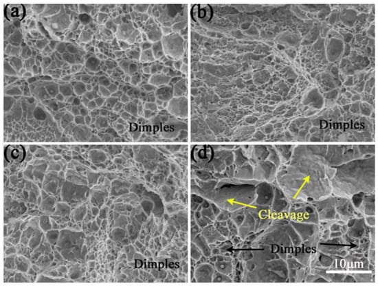
Figure 9.
Impact fracture of deposited metals, (a) Cu 0.62, (b) Cu 1.38, (c) Cu 1.79, (d) Cu 2.32. There is mainly dimple of Cu 0.62, Cu 1.38, and Cu 1.79, while it are dimple and cleavage of Cu 2.32.
4. Discussion
4.1. Effects of Cu on Microstructure and Precipitates Characterization
The effect of Cu element on the phase transformation temperature of deposited metal was simulated by JMatPro software (Figure 10). The start temperature of bainite (Bs) of deposited metals are 424 °C (Cu 0.62), 432 °C (Cu 1.38), 433 °C (Cu 1.79), and 446 °C (Cu 2.32) at a cooling rate of 25 °C/s. The difference values (Δ) of Bs and Ms point increases from 372 K to 416 K with increase of Cu addition. This indicates that Cu addition encourages the transformation amount of bainite during welding. Due to quick cooling rate in the welding process, bainite transformation is not complete. The subsequent cooling below Ms point will stimulate the formation of RA, martensite, and M-A constituents. Thus, the microstructure of deposited metal is modified from bainite and massive martensite to bainite and M-A constituent as the addition of Cu increase from 0.62% to 2.32%.
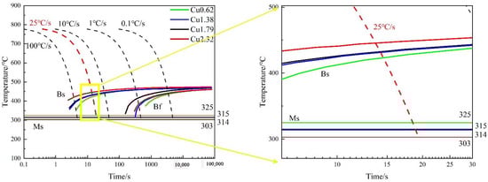
Figure 10.
Continuous cooling transformation curves of deposited metals. The difference values (Δ) of Bs and Ms point increases with increase of Cu addition.
Due to the effect of Cu on phase transformation, we counted the area fraction of equivalent diameter of martensite and M-A constituents in deposited metals (Figure 11). As for Cu 0.62, martensite is mainly distributed in slat and block with large size. The diameter of martensite decreases obviously and becomes elongated of Cu 1.38. And massive martensite still exists. Martensite is further refined and smaller granular M-A constituents appear of Cu 1.79. The martensite mainly exists as M-A constituents with effective diameter less than 1.5 μm of Cu 2.32. Moreover, the area fraction of martensite and M-A constituents of deposited metals decreases with increase of Cu addition (Figure 2). The M-A constituents in bainite mainly exists as strip and granular [29]. During the welding cooling process, the amount of bainite transformation increases with increase of Cu content. The percentage of untransformed austenite decreases, and it is segmented by formed bainite. Therefore, the area fraction of martensite and M-A constituents decreased. Thus, the M-A constituents changes from strip into granular. In a word, the Cu addition of deposited metals inhibits the formation of martensite during welding.
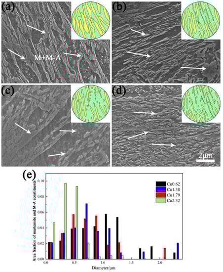
Figure 11.
High-magnification SEM morphologies with schematic diagram (a–d) and equivalent diameter distribution of martensite and M-A constituents (e). (a) Cu 0.62, (b) Cu 1.38, (c) Cu 1.79, (d) Cu 2.32. The area fraction and size of martensite and M-A constituents of deposited metals decreases with increase of Cu addition.
The HRTEM results show that Cu precipitates in deposited metals exist as BCC and FCC structure. With increase of Cu content, the fraction and diameter of Cu precipitates increases significantly (Figure 12). The Cu precipitates do not precipitate from the austenite, because Cu has a high solubility in austenite [30,31]. As the deposited metal transforms from austenite into α-Fe, the solubility of Cu decreases dramatically. Then, the Cu particles precipitates. The crystal structure of Cu precipitates in Cu 0.62 is BCC (Figure 12a). The spacing between every three atomic layers is 0.60 nm. The mismatch degree between BCC Cu precipitates and α-Fe matrix is 1.22%, confirming the coherent relationship. The crystal structures of Cu precipitates in Cu 1.38, Cu 1.79, and Cu 2.32 are both FCC with distance between every atomic layer of 0.39 nm, 0.48 nm, and 0.39 nm, respectively (Figure 12b–d). The FCC Cu precipitates lose their coherency with α-Fe matrix and grow longitudinally, revealing a shape of ellipsoid. The aspect ratio (length/width) of Cu precipitates are 1.63 (Cu 1.38), 1.83 (Cu 1.79) and 1.87 (Cu 2.32), increasing with increase of Cu addition.
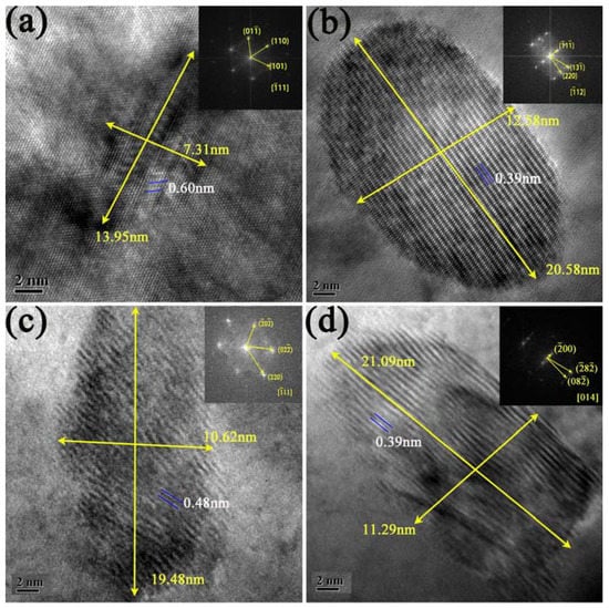
Figure 12.
HRTEM images of deposited metals. (a) Cu 0.62, (b) Cu 1.38, (c) Cu 1.79, (d) Cu 2.32. The Cu precipitates is BCC structure in Cu 0.62, and it is FCC structure in Cu 1.38, Cu 1.79, and Cu 2.32. The aspect ratio (length/width) of Cu precipitates are increases with increase of Cu addition (1.38–2.32%).
4.2. Strengthening of Cu Precipitates and Dislocation Density
It can be seen from the engineering stress-strain curves (Figure 8a) that Cu addition (0.62–1.79%) can significantly improve the yield strength and ultimate tensile strength of deposited metals, while the yield strength of Cu 2.32 decreased obviously. Bainite and martensite both exist in lath structure (Figure 5). The lower the C content is, the similar properties of martensite and bainite are. The difference between bainite and martensite is the lower transformation temperature of martensite, resulting the higher dislocation density due to more defects and high carbon content. The BCC and FCC Cu precipitation can obviously improve the strength of deposited metal. According to discussion above, the effect of Cu addition on the yield strength of deposited metals is mainly in two consequences: precipitation strengthening and dislocation strengthening.
The dislocation density of deposited metals calculated by MWH method is 2.18 × 10¹⁴ m−2 (Cu 0.62), 2.48 × 10¹⁴ m−2 (Cu 1.38), 2.24 × 10¹⁴ m−2 (Cu 1.79), 5.1 × 10¹³ m−2 (Cu 2.32) (Figure 3). The dislocation strengthening (σdis) can be computed by the Taylor formula [32] as below:
where α is the Taylor constant, α = 0.4; M is the average Taylor factor, M = 2.77 [33]; G is the shear modulus, G = 80 GPa [34].
The precipitation strengthening of materials is the relationship between the precipitates and dislocations via two approaches, cutting over model and bypass model [35,36,37]. In this experiment, Cu precipitates with diameter of 14–28 nm is BCC and FCC structure, The diameter of Cu precipitates is larger than critical size (5.6 nm) [38]. So, it is reasonable for the dislocations loop around the nano-Cu precipitates by the Orowan mechanism [39]. In this point, the lattice resistance of dislocation motion (P-N force, τp) can be calculated as follows [40]:
where d is diameter of Cu precipitates; K is constant, K = 1; f is the volume fraction of Cu precipitates. According to Formula (2), the P-N forces generated by the interaction of Cu precipitates are 26.4 MPa (Cu 0.62), 33.3 MPa (Cu 1.38), 85.5 MPa (Cu 1.79), 140.6 MPa (Cu 2.32), respectively. For α-Fe, the Schmid phase factor is close to 2. The lattice resistance of dislocation slip in crystal structure can be transformed from shear stress to normal stress, and the formula is as follows:
where σper is the theoretical strengthening value of Cu precipitates, which are 53 MPa (Cu 0.62), 67 MPa (Cu 1.38), 171 MPa (Cu 1.79), 281 MPa (Cu 2.32).
The contributions of two kinds strengthening mechanisms to yield strength of deposited metals are shown in Figure 13. The Cu precipitates can effectively improve the yield strength of deposited metals, and the maximum values of precipitation strengthening can reach 281 MPa. Because the dispersion of Cu precipitates in deposited metals can serve as effective barriers for dislocation movement. At the same time, the effect of dislocation density enhancement of Cu 0.62, Cu 1.38, and Cu 1.79 is similar, but the dislocation density of Cu 2.32 reduce obviously, leading to dislocation strengthening value decreases by half. The Cu 1.79 obtains the best yield strength. Because the dislocation density of it remains at a high level, and Cu precipitation provides 171 MPa strengthening.
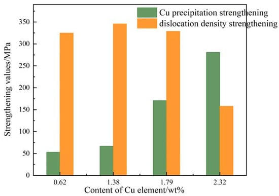
Figure 13.
Contributions of precipitation strengthening and dislocation strengthening of deposited metals. The Cu 1.79 obtains the best yield strength due to the high dislocation density and Cu precipitation.
4.3. Toughening Mechanism of Deposited Metals
The addition of Cu element mainly reduces the initiation energy, but has little effect on the propagation energy (Table 3). The crack initiation energy of Cu 2.32 decreases by half compared with that of Cu 0.62. The impact toughness reduced with increase of Cu addition, which can be explained from matrix microstructure and Cu precipitation.
The 0.62–2.32% Cu addition can encourage the formation of bainite and inhibits formation of martensite. And Cu elements are austenite stabilizers [14]. The volume fraction of RA increases with the increase of 0.62–1.79% Cu content, which can enhance the toughness by TRIP effect. As for Cu 2.32, the area fraction of RA decreases. Because the Cu element forms many precipitates, which weakened the stabilizing effect of residual austenite. The M-A constituent is a brittle phase, which is detrimental to toughness. The martensite and M-A constituents refines with increase of Cu addition, and the granular M-A constituents are formed in Cu 1.79 and Cu 2.32, the impact toughness could be improved. Thus, the microstructure of deposited metals with Cu addition should be good for toughness. However, there are BCC and FCC Cu precipitates of deposited metals (Figure 7). The equivalent diameter of Cu precipitates is 14–28 nm, and the precipitation of Cu belongs to dispersion precipitation without segregation near grain boundary. It has been proved that BCC Cu precipitation are harmless to the toughness of deposited metals [21]. Thus, the Cu 0.62 has the best impact toughness (64.56 J). With 1.38–2.32% Cu content, the structure of Cu precipitates changes from BCC to FCC, and diameter increases significantly (Figure 12). Results show that Cu precipitation greatly degrading the crack initiation energy of Cu 1.38, Cu 1.79, and Cu 2.32, because the FCC Cu precipitates has incoherent structure with the matrix. The large size of FCC Cu precipitates is another reason of the easy crack nucleation. Because precipitates with large diameter often facilitate the stress concentration and nucleation of cracks [41,42]. Thus, the FCC Cu-rich precipitation leads to a reduced impact toughness of deposited metals. Compared with the microstructure, Cu precipitates plays a more important role on toughness.
It is noteworthy that the toughness of Cu 1.79 is superior to that of Cu 1.38 and Cu 2.32, although the Cu precipitates are both FCC structures. The area fractions of martensite and M-A constituents of Cu 1.79 are 28.1% (Figure 2), which is lower than Cu 1.38. And the volume fraction of RA is higher than that of Cu 1.38 and Cu 2.32 (Figure 3), which can effectively improve toughness through TRIP effect. Meanwhile, the width of lath structure of Cu 1.79 is ~170 nm (Figure 5), and the area fractions of high angle grain boundaries is 23.54% (Figure 4). During the deformation process, the fine lath structure and high angle grain boundaries can reduce the crack nucleation location and improve the crack propagation path, thus toughness is improved. When Cu content reaches 2.32%, the high volume fraction of FCC Cu precipitation (Table 2) significantly degrades the crack initiation energy, resulting in a sharp decline of impact toughness.
The previous studies usually used post-weld heat treatment for materials with Cu addition to obtain the nano-size of Cu precipitation [21]. In this experimental, the TIG welding was used and the height of each layer is controlled below 1.88 mm. Because the latter layer would have a gravimetry effect on the former layer, promoting Cu precipitation. So, Cu precipitation can be observed in the condition of welding. Research shown that the strengthening value of copper-bearing weld metal can reach 166 MPa [22]. The results of this paper show that the precipitation strengthening of Cu can reach 281 MPa. However, the impact toughness of deposited metal is not well due to large size of Cu precipitation. The new welding material is mainly considered to match 1000 MPa grade high strength low alloy steel. The impact properties of deposited metal can be further improved by strictly controlling the welding conditions, and the structure and performance of welding joints prepared by this new welding wire will be studied later.
5. Conclusions
The multiphase microstructure of deposited metals with 0.62–2.32% Cu addition can bring an enhanced strength-toughness balance. This metal cored wire possesses a well weldability and is suited for applications of high strength steels. Based on the research of microstructure and mechanical properties of high strength deposited metals with Cu addition obtained by metal cored wire, the following conclusions are drawn.
The multiphase microstructure of deposited metals consists of bainite, martensite, residual austenite, and M-A constituents. With increase of Cu addition (0.61–2.32%), the fraction of martensite and M-A constituents decreases from 32.2% into 27.2%. As well as the shapes of them refines from strip to granular. The BCC and FCC Cu precipitates are observed in deposited metals. With increase of Cu content, the volume fraction of Cu precipitates increased significantly, and the size of them increase from 14 nm to 28 nm.The yield strength and ultimate tensile strength of deposited metals are greatly improved with the increase of Cu addition, which can reach the maximum value 961 MPa and 1286 MPa of Cu 1.79. As for Cu 1.79, the dislocation density maintains at high level, and the precipitation strengthening reaches 171 MPa. The deposited metals achieve high strength with Cu addition at the expense of impact toughness. The impact values of deposited metal at −20 °C are 64.56 J (Cu 0.62), 52.56 J (Cu 1.38), 56.39 J (Cu 1.79), and 42.66 J (Cu 2.32), respectively. The FCC Cu precipitates are responsible for the reduced toughness of deposited metal with 1.38–2.32% Cu. The Cu precipitation reduces the crack initiation energy of deposited metals, which has little effect on the propagation energy. The deposited metal with 1.79% Cu addition shows an excellent strength-ductility balance.
Author Contributions
Designing and conducting the experiments, data analyzing, wring the paper, J.W.; supervising the experiments, assisting in the experiments, X.D.; revising the paper, assisting in the experiments, C.L.; assisting in the experiments, D.W. All authors have read and agreed to the published version of the manuscript.
Funding
This research was funded by the National Natural Science Foundation of China (grant Nos. 52074191 and 51804217).
Institutional Review Board Statement
Not applicable.
Informed Consent Statement
Not applicable.
Data Availability Statement
Data is contained within the article.
Conflicts of Interest
The authors declare no conflict of interest.
References
- World Steel Association. Future Stee Lvehicle Results and Reports & Cost Model. 2020. Available online: https://www.worldautosteel.org/projects/future-steel-vehicle/phase-2-results/ (accessed on 15 February 2020).
- Metlitskii, V. Flux-cored wires for arc welding and surfacing of cast iron. Weld. Int. 2008, 22, 796–800. [Google Scholar] [CrossRef]
- Gavrilov, S.N.; Khitsov, O.V. Metal-powder wires for mechanized and automatic gas-shielded welding of low carbon and low-alloy steels. Weld. Int. 2014, 28, 234–236. [Google Scholar] [CrossRef]
- William, R.; Honeycombe, K. Steels: Microstructure and Properties; Edward Arnold: London, UK, 1981. [Google Scholar]
- Jiao, Z.B.; Luan, J.H.; Guo, W.; Poplawsky, J.D.; Liu, C.T. Effects of welding and post-weld heat treatments on nanoscale precipitation and mechanical properties of an ultra-high strength steel hardened by NiAl and Cu nanoparticles. Acta Mater. 2016, 120, 216–227. [Google Scholar] [CrossRef]
- Chen, R.; Kong, H.J.; Luan, J.H.; Wang, A.D.; Jiang, P.; Liu, C.T. Effect of external applied magnetic field on microstructures and mechanical properties of laser welding joint of medium-Mn nanostructured steel. Mater. Sci. Eng. A 2020, 792, 139787. [Google Scholar] [CrossRef]
- Kalpana, J.; Rao, P.S.; Rao, P.G. A review on techniques for improving the mechanical properties of fusion welded joints. Eng. Solid Mech. 2017, 4, 213–224. [Google Scholar] [CrossRef]
- Chen, K.; Jiang, Z.; Liu, F.; Li, H.; Ma, X.; Zhao, B.; Kang, C.; Li, Y. Enhanced mechanical properties by retained austenite in medium-carbon Si-rich microalloyed steel treated by quenching-tempering, austempering and austempering-tempering processes. Mater. Sci. Eng. A 2020, 790, 139742. [Google Scholar] [CrossRef]
- Gao, G.; Zhang, H.; Tan, Z.; Liu, W.; Bai, B. A carbide-free bainite/martensite/austenite triplex steel with enhanced mechanical properties treated by a novel quenching-partitioning-tempering process. Mater. Sci. Eng. A 2013, 559, 165–169. [Google Scholar] [CrossRef]
- Yu, X.; Caron, J.L.; Babu, S.S.; Lippold, J.C.; Isheim, D.; Seidman, D.N. Strength recovery in a high-strength steel during multiple weld thermal simulations. Metall. Mater. Trans. A 2011, 42, 3669–3679. [Google Scholar] [CrossRef]
- Jamari, J.; Ammarullah, M.I.; Santoso, G.; Sugiharto, S.; Supriyono, T.; Prakoso, A.T.; Basri, H.; van der Heide, E. Computational Contact Pressure Prediction of CoCrMo, SS 316L and Ti6Al4V Femoral Head against UHMWPE Acetabular Cup under Gait Cycle. J. Funct. Biomater. 2022, 13, 64. [Google Scholar] [CrossRef]
- Wu, S.; Wang, D.; Zhao, C.; Zhang, Z.; Li, C.; Di, X. Enhanced toughness of Fe-12Cr-5.5Ni-Mo-deposited metals through formation of fine reversed austenite. J. Mater. Sci. 2018, 53, 15679–15693. [Google Scholar] [CrossRef]
- Luo, X.; Chen, X.; Wang, T.; Pan, S.; Wang, Z. Effect of morphologies of martensite–austenite constituents on impact toughness in intercritically reheated coarse-grained heat-affected zone of HSLA steel. Mater. Sci. Eng. A 2018, 710, 192–199. [Google Scholar] [CrossRef]
- Kapoor, M.; Isheim, D.; Ghosh, G.; Vaynman, S.; Fine, M.E.; Chung, Y.-W. Aging characteristics and mechanical properties of 1600 MPa body-centered cubic Cu and B2-NiAl precipitation-strengthened ferritic steel. Acta Mater. 2014, 73, 56–74. [Google Scholar] [CrossRef]
- Kolli, R.P.; Seidman, D.N. The temporal evolution of the decomposition of a concentrated multicomponent Fe-Cu-based steel. Acta Mater. 2008, 56, 2073–2088. [Google Scholar] [CrossRef]
- Isheim, D.; Gagliano, M.S.; Fine, M.E.; Seidman, D.N. Interfacial segregation at Cu-rich precipitates in a high-strength low-carbon steel studied on a sub-nanometer scale. Acta Mater. 2006, 54, 841–849. [Google Scholar] [CrossRef]
- Kim, S.H.; Yeon, S.-M.; Lee, J.H.; Kim, Y.W.; Lee, H.; Park, J.; Lee, N.-K.; Choi, J.P.; Aranas, C., Jr.; Lee, Y.J.; et al. Additive manufacturing of a shift block via laser powder bed fusion: The simultaneous utilisation of optimised topology and a lattice structure. Virtual Phys. Prototyp. 2020, 15, 460–480. [Google Scholar] [CrossRef]
- Vaynman, S.; Isheim, D.; Kolli, R.P.; Bhat, S.P.; Seidman, D.N.; Fine, M.E. High-strength low-carbon ferritic steel containing Cu-Fe-Ni-Al-Mn precipitates. Metall. Mater. Trans. A 2008, 39, 363–373. [Google Scholar] [CrossRef]
- Mattes, V.R. Microstructure and Mechanical Properties of HSLA-100 Steel; Naval Postgraduate School: Monterey, CA, USA, 1990. [Google Scholar]
- Czyryca, E.J.; Vassilaros, M.G. Advances in Low Carbon, High Strength Ferrous Alloys. J. Chem. Inf. Model. 1993, 92/63, 1–44. [Google Scholar]
- Wang, J.; Di, X.; Li, C.; Wang, D. Characterization of nanoscale precipitates and enhanced mechanical properties of high strength weld metals containing Cu additions after PWHT. Metall. Res. Technol. 2022, 119, 119. [Google Scholar] [CrossRef]
- Wang, H.; Yu, X.; Isheim, D.; Seidman, D.; Babu, S.S. High strength weld metal design through nanoscale copper precipitation. Mater. Des. 2013, 50, 962–967. [Google Scholar] [CrossRef]
- Kong, H.; Jiao, Z.; Lu, J.; Liu, C.T. Low-carbon advanced nanostructured steels: Microstructure, mechanical properties, and applications. Sci. China Mater. 2021, 64, 1580–1597. [Google Scholar] [CrossRef]
- Wang, H.H.; Tong, Z.; Hou, T.P.; Wu, K.M.; Mehmood, T. Effects of evolution of nanoscale copper precipitation and copper content on mechanical properties of high-strength steel weld metal. Sci. Technol. Weld. Join. 2016, 22, 191–197. [Google Scholar] [CrossRef]
- Wang, J.; Di, X.; Li, C.; Wang, D. The influence of Ni on bainite/martensite transformation and mechanical properties of deposited metals obtained from metal-cored wire. Metals 2021, 11, 1971. [Google Scholar] [CrossRef]
- Mao, G.; Cao, R.; Yang, J.; Jiang, Y.; Wang, S.; Guo, X.; Yuan, J.; Zhang, X.; Chen, J. Effect of nickel contents on the microstructure and mechanical properties for low-carbon bainitic weld metals. J. Mater. Eng. Perform. 2017, 26, 2057–2071. [Google Scholar] [CrossRef]
- Takebayashi, S.; Kunieda, T.; Yoshinaga, N.; Ushioda, K.; Ogata, S. Comparison of the dislocation density in martensitic steels evaluated by some X-ray diffraction methods. ISIJ Int. 2010, 50, 875–882. [Google Scholar] [CrossRef]
- Fang, H.S. Bainite Transformation; Science Press: Beijing, China, 1999. [Google Scholar]
- Zhang, T.T. Study on Interlaced Multiphase Microstructure and Strengthening and Toughening Mechanism of Deposited Metals of Metal Powder-Cored Wires for 800 MPa Grade High Strength Steels. Ph.D. Thesis, Tianjin University, Tianjin, China, 2016. [Google Scholar]
- Liu, C.T.; Jiao, Z.B.; Luan, J.H. Copper-rich nanoclusters: Ferritic steels strengthened. In Encyclopedia of Iron, Steel, and Their Alloys; CRC Press: Boca Raton, FL, USA, 2015. [Google Scholar]
- Jiao, Z.B.; Luan, J.H.; Miller, M.K.; Yu, C.Y.; Liu, C.T. Group precipitation and age hardening of nanostructured Fe-based alloys with ultra-high strengths. Sci. Rep. 2016, 6, 21364. [Google Scholar] [CrossRef]
- Ungár, T.; Harjo, S.; Kawasaki, T.; Tomota, Y.; Ribárik, G.; Shi, Z. Composite behavior of lath martensite steels induced by plastic strain, a new paradigm for the elastic-plastic response of martensitic steels. Metall. Mater. Trans. A 2017, 48, 159–167. [Google Scholar] [CrossRef]
- He, S.H.; He, B.B.; Zhu, K.Y.; Huang, M.X. On the correlation among dislocation density, lath thickness and yield stress of bainite. Acta Mater. 2017, 135, 382–389. [Google Scholar] [CrossRef]
- Edalati, K.; Horita, Z. High-pressure torsion of pure metals: Influence of atomic bond parameters and stacking fault energy on grain size and correlation with hardness. Acta Mater. 2011, 59, 6831–6836. [Google Scholar] [CrossRef]
- Wen, Y.R.; Li, Y.P.; Hirata, A.; Zhang, Y.; Fujita, T.; Furuhara, T.; Liu, C.T.; Chiba, A.; Chen, M.W. Synergistic alloying effect on microstructural evolution and mechanical properties of Cu precipitation-strengthened ferritic alloys. Acta Mater. 2013, 61, 7726–7740. [Google Scholar] [CrossRef]
- Hall, E.O. The deformation and ageing of mild steel: III discussion of results. Proc. Phys. Soc. Sect. B 1951, 64, 747–752. [Google Scholar] [CrossRef]
- Fine, M.E.; Isheim, D. Origin of copper precipitation strengthening in steel revisited. Scr. Mater. 2005, 53, 115–118. [Google Scholar] [CrossRef]
- Monzen, R.; Jenkins, M.L.; Sutton, A.P. The bcc-to-9R martensitic transformation of Cu precipitates and the relaxation process of elastic strains in an Fe-Cu alloy. Philos. Mag. A 1999, 80, 711–723. [Google Scholar] [CrossRef]
- Lozano-Perez, S.; Jenkins, M.L.; Titchmarsh, J.M. Evidence for deformation-induced transformations of Cu-rich precipitates in an aged FeCu alloy. Philos. Mag. Lett. 2006, 86, 367–374. [Google Scholar] [CrossRef]
- Bandi, R.W. Second phases in steel: New analytical methods can identify the types and amounts of complex precipitates in steel. Science 1977, 196, 136–142. [Google Scholar] [CrossRef] [PubMed]
- Dhua, S.K.; Ray, A.; Sarma, D.S. Effect of tempering temperatures on the mechanical properties and microstructures of HSLA-100 type copper-bearing steels. Mater. Sci. Eng. A 2001, 318, 197–210. [Google Scholar] [CrossRef]
- Liu, Q.; Wen, H.; Zhang, H.; Gu, J.; Li, C.; Lavernia, E.J. Effect of multistage heat treatment on microstructure and mechanical properties of high-strength low-alloy steel. Metall. Mater. Trans. A 2016, 47, 1960–1974. [Google Scholar] [CrossRef]
Publisher’s Note: MDPI stays neutral with regard to jurisdictional claims in published maps and institutional affiliations. |
© 2022 by the authors. Licensee MDPI, Basel, Switzerland. This article is an open access article distributed under the terms and conditions of the Creative Commons Attribution (CC BY) license (https://creativecommons.org/licenses/by/4.0/).