Article

Casting Process at Roll Bite in Strip Cast Using Vertical-Type High-Speed Twin-Roll Caster

1
Department of Mechanical Engineering, Osaka Institute of Technology, Omiya Asahi-ku, Osaka 535-8585, Japan
2
Graduate School of Osaka Institute of Technology, Omiya Asahi-ku, Osaka 535-8585, Japan
*
Author to whom correspondence should be addressed.
Metals 2022, 12(7), 1169; https://doi.org/10.3390/met12071169
Submission received: 30 May 2022 / Revised: 2 July 2022 / Accepted: 6 July 2022 / Published: 9 July 2022
(This article belongs to the Special Issue Casting of Aluminum Alloy and Porous Metal)

Abstract

:
The solidification process in strip casting using a vertical-type high-speed twin-roll caster was clarified by inserting a 0.1 mm diameter K-type thermocouple into a strip during casting. The roll speeds of the copper rolls were 10 m/min and 30 m/min, and the roll loads were 5 kN and 20 kN. Al-Si alloys with a Si content of 2%, 6%, and 12% were used to investigate the influence of latent heat and viscosity in the semisolid state. The strip temperature increased after exiting the rolls. This indicated that the inside of the strip had not completely solidified at the roll bite, and secondary cooling was necessary to rapidly solidify the inside of the strip. The distance from the roll bite to the solidification starting position ranged from 30 mm to 63 mm. The cooling rate and degree of supercooling increased as the Si content decreased. The cooling rate ranged from 400 °C/s to 4000 °C/s. The cooling rate and degree of supercooling decreased as the viscosity of the semisolid increased.

Graphical Abstract

1. Introduction

A twin-roll caster has several advantages. For example, it shortens the processing time, saves energy, and allows rapid solidification. Many previous studies have examined the conventional twin-roll caster for aluminum alloys (CTRCA). A disadvantage of the CTRCA is the low casting speed. Increasing the casting speed was actively researched in the 1990s [1,2,3,4,5,6]. The roll load and setback were increased, and the thickness of the strip was reduced to increase the roll speed. A thinner strip cools more rapidly than a thicker strip, and the roll speed increases. The contact length between the strip and the roll increases as the setback increases. When the roll speed increases, the thickness of the solidification layer decreases as the solidification time decreases. The setback was increased to make the strip thick enough to attain a proper reduction in the strip. In the CTRCA, a thin strip is the most important factor for increasing the roll speed. However, the roll speed of the CTRCA has not increased since the 1990s [7,8,9,10,11]. No effective method to increase the roll speed has been found, despite the demand for such a technique. A vertical-type high-speed twin-roll caster (VHSTRC) was proposed to increase the casting speed of an aluminum alloy strip [12,13,14,15]. Conceptually, the CTRCA and the VHSTRC are completely different. The roll speed of the CTRCA is usually slower than 2 m/min, and the roll load is usually greater than 4 kN/mm. The VHSTRC can cast aluminum alloy strips at speeds higher than 10 m/min, reaching about 90 m/min. The roll load is usually smaller than 0.5 kN/mm. In the VHSTRC, the roll gap depends on the strip thickness, because the gap between the rolls is not fixed, and the strip is pressed by a very small load. In the CTRCA, the roll gap is fixed during casting. The strip cast by the VHSTRC is not actively rolled with large deformation, as in the CTRCA. The strip thickness is affected by the roll speed, solidification length, and roll load in the VHSTRC. The rolls of the CTRCA are usually made of tool steel for hot working, and a parting material is sprayed on the rolls to prevent the strip from sticking to the roll. The rolls of the VHSTRC are made of copper alloy, and a parting material is not used. Because the thermal conductivity of the copper alloys is much higher than that of the tool steel, the surface temperature of the copper alloy roll does not reach the temperature at which strip sticking occurs. The aluminum alloy is more rapidly solidified by the copper alloy roll than the tool steel roll. The parting material provides heat resistance between the roll and the molten metal. The lack of a parting material increases the heat transfer between the aluminum alloy and the roll. Thus, the casting speed of the VHSTRC is much higher than that of the CTRCA, due to the use of copper alloy rolls and the elimination of the parting material. The VHSTRC can be developed for casting clad strips due to its high cooling ability [16]. The VHSTRC can cast a hyper-eutectic Al-20%Si alloy strip that has a wide solidification temperature range [17]. The excellent cooling ability made the AlSiFe intermetallic compound very fine, and the bending ability of the recycled aluminum alloy was improved [18].
The cross-sectional microstructure of a strip cast using the VHSTRC is different from that of a strip cast using the CTRCA. In the latter, the microstructure solidified by both rolls is columnar, and this structure continues to the center in the thickness direction [2]. The strip is plastically deformed by the rolls. In a strip cast using the VHSTRC, the cross-section of the strip usually consists of three layers [14,19,20]. Two of these layers are near the surfaces, and the other layer lies in between. This center layer is hereafter called a “band zone” [19]. The microstructure of the outer side layers is usually equiaxial. The microstructure of the band zone comprises globular crystals in the Al-Si alloy strip. It is estimated that the equiaxial dendrites are crystalized by the rapid solidification. The formation mechanism of the band zone and the globular crystals has not been clarified.
It is estimated that the solidification process (e.g., temperature inside the strip, solidification starting position, supercooling, and cooling rate) for a strip cast using the VHSTRC is different from that of a strip cast using the CTRCA. The solidification process of the VHSTRC has not been clarified. It is thought that the usefulness of the VHSTRC will increase when the casting process is clarified. Therefore, in this study, the solidification process was investigated by inserting a thin thermocouple into the band zone of the casting strip to clarify the casting process and the formation of the band zone.
In previous studies, the cooling rate of a strip cast using the VHSTRC was estimated by inserting a thermocouple into the casting strip. These studies evaluated the effect of the roll load on the cooling rate of an Al-7%Si-3%Mg strip [20]; the effect of the roll speed on the cooling rate of Al-2%Ai [21]; and the cooling rate of Al-Mn, Al-Mn-Fe, and Al-Mn-Si strips [22]. These studies did not insert a thermocouple into the casting strip, except to examine the cooling rate. The investigation of other solidification processes and discussions regarding the solidification of the aluminum alloy between the rolls are essential for clarifying the properties of the VHSTRC. Therefore, in this study, the effects of roll speed, roll load, and the Si content of the Al-Si alloy on strip temperature at the roll bite, supercooling, solidification starting position, cooling rate, and strip temperature after exiting the rolls were investigated by inserting a thermocouple into a casting strip.
The solidification of the band zone was evaluated based on the strip temperature increase after it exited the rolls. The usefulness of the secondary cooling of the strip after it exited the rolls was indicated. The effect of the viscosity of the semisolid metal on decreasing the liquidus temperature by supercooling and the cooling rate were also studied.

2. Experimental Methods

The experimental procedure using the VHSTRC is shown in Figure 1. The diameter and width of the copper rolls were 300 mm and 100 mm, respectively. The distance from the tip of the back dam plate to the roll bite, 100 mm, was defined as the solidification length. The roll speeds were 10 m/min and 30 m/min. The roll loads were 5 kN and 20 kN. Al-Si alloys with a Si content of 2%, 6%, and 12% (by mass) were used to investigate the effect of the latent heat of the aluminum alloy on the solidification process. The latent heat of Al-Si alloys increases as the Si content increases [18]. The melt head was 200 mm. The superheating temperature for the molten metal was 50 °C. Each Al-Si alloy was cast under each set of conditions three times.
A K-type thermocouple with a diameter of 0.1 mm was used to create time–temperature diagrams. Stainless steel wire 0.7 mm in diameter was attached to the thermocouple to lead it into the molten metal and the strip. The initial roll gap was 1 mm. The lead wire was set between the rolls rotating at the designated roll speed, as shown in Figure 1a. Molten metal was poured into the melt head, and the lead wire was dragged by the strip, as shown in Figure 1b. The thermocouple was dragged into the molten metal pool and the strip after reaching a steady state, as shown in Figure 1c. Figure 1d is an overhead photograph of the equipment depicted in Figure 1b. The roll was pushed by coil springs, and the roll gap changed along the thickness of the strip. The tip of the K-type thermocouple with the lead wire and the thermocouple embedded in the strip are shown in Figure 2. A GL240-UM-801 data logger (Graphtec Inc., Totsuka, Yokohama, Japan) was used for data recording, and the recorder took a sample every 0.01 s. The time–temperature diagrams were created using an insulated mold to acquire the liquidus and solidus temperatures in the equilibrium state. The length, width, and height of the insulator mold were 50 mm, 50 mm, and 40 mm, respectively. The chemical compositions of the Al-Si alloys are shown in Table 1.

3. Results

3.1. Cooling Curves

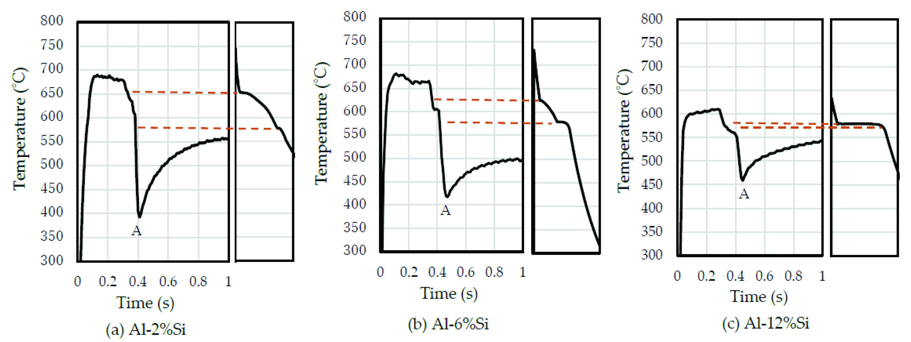
The cooling curves (time–temperature diagrams) for the VHSTRC and the insulated mold are shown in Figure 3. The left side and right side of each panel are the cooling curves for the VHSTRC and insulated mold, respectively. The roll speed was 30 m/min and the roll load was 20 kN. The temperatures, indicated by dashed lines, represent the solidus and liquidus temperatures for the cooling curve of the aluminum alloys solidified using the insulated mold. In the cooling curves of the VHSTRC, the liquidus temperature can be confirmed, but the solidus temperature cannot. The cooling curve shows that supercooling of the liquidus temperature occurred. The temperature rapidly dropped and then immediately increased. It was found that the temperature of the valley (shown by “A” in Figure 3) is the temperature of the roll bite (shown in Figure 1b) from the roll speed and melt head. The cooling curve shows that the temperature of the strip increased after it exited the roll.

3.2. Strip Thickness

The effects of roll speed, roll load, and Si content on the thickness of the Al-Si strip are shown in Figure 4. The roll speeds were 10 m/min and 30 m/min, and the roll loads were 5 kN and 20 kN. The Si contents were 2%, 6%, and 12%. In an Al-Si alloy, the latent heat increases as the Si content increases [23]. The strip thickness decreased as the Si content increased. The strip thickness decreased as the roll speed and the roll load increased from 5 m/min to 30 m/min and from 5 kN to 20 kN, respectively. In the VHSTRC, the strip thickness was affected by the roll speed, roll load, and latent heat. The effect of the roll load on the strip thickness increased as the strip thickness increased by decreasing the roll speed from 30 m/min to 10 m/min.

3.3. Strip Temperature at Roll Bite

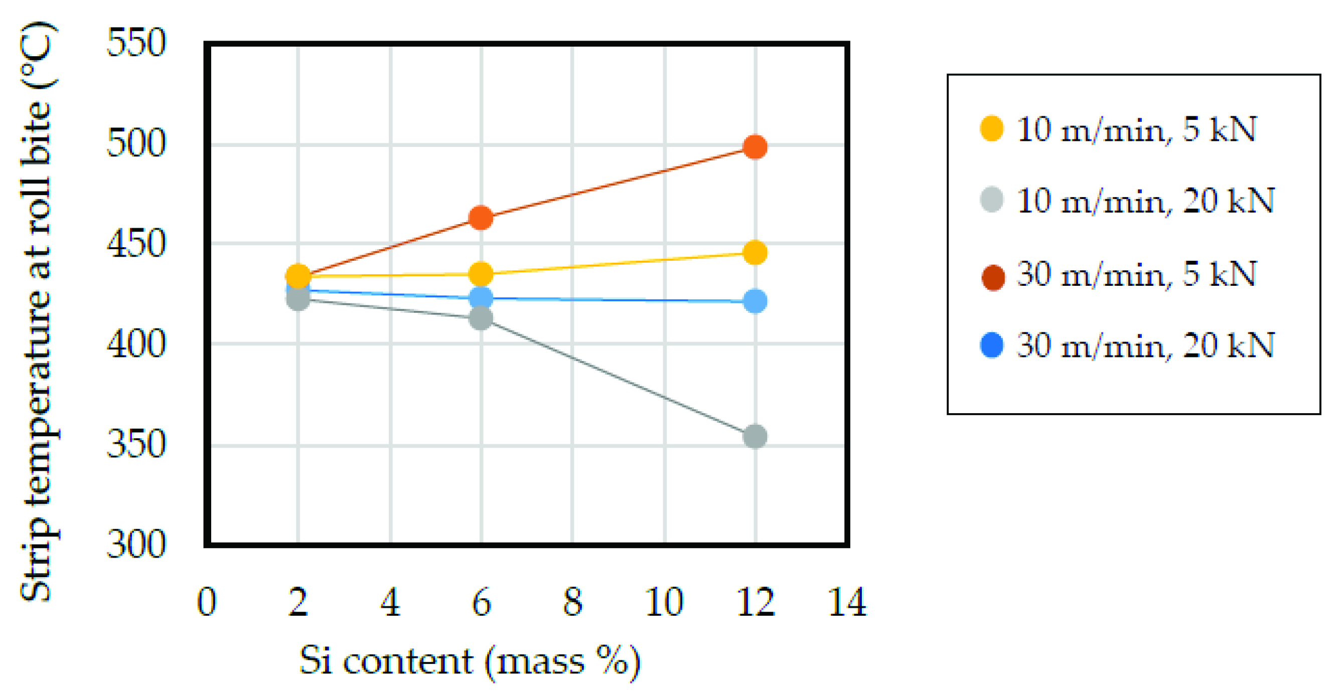
The effects of roll speed, roll load, and Si content on the strip temperature at the roll bite are shown in Figure 5. The effects of the roll speed and the roll load on the strip temperature at the roll bite decreased as the Si content decreased. The strip temperature had a tendency to increase as the roll speed increased from 10 m/min to 30 m/min with the same roll load. The temperature had a tendency to decrease as the roll load increased from 5 kN to 20 kN at the same roll speed. When the roll speed was 10 m/min and the roll load was 20 kN, the strip temperature decreased sharply. When the roll speed was 30 m/min and the roll load was 5 kN, the strip temperature gradually increased as the Si content increased.

3.4. Decrease in Liquidus Temperature

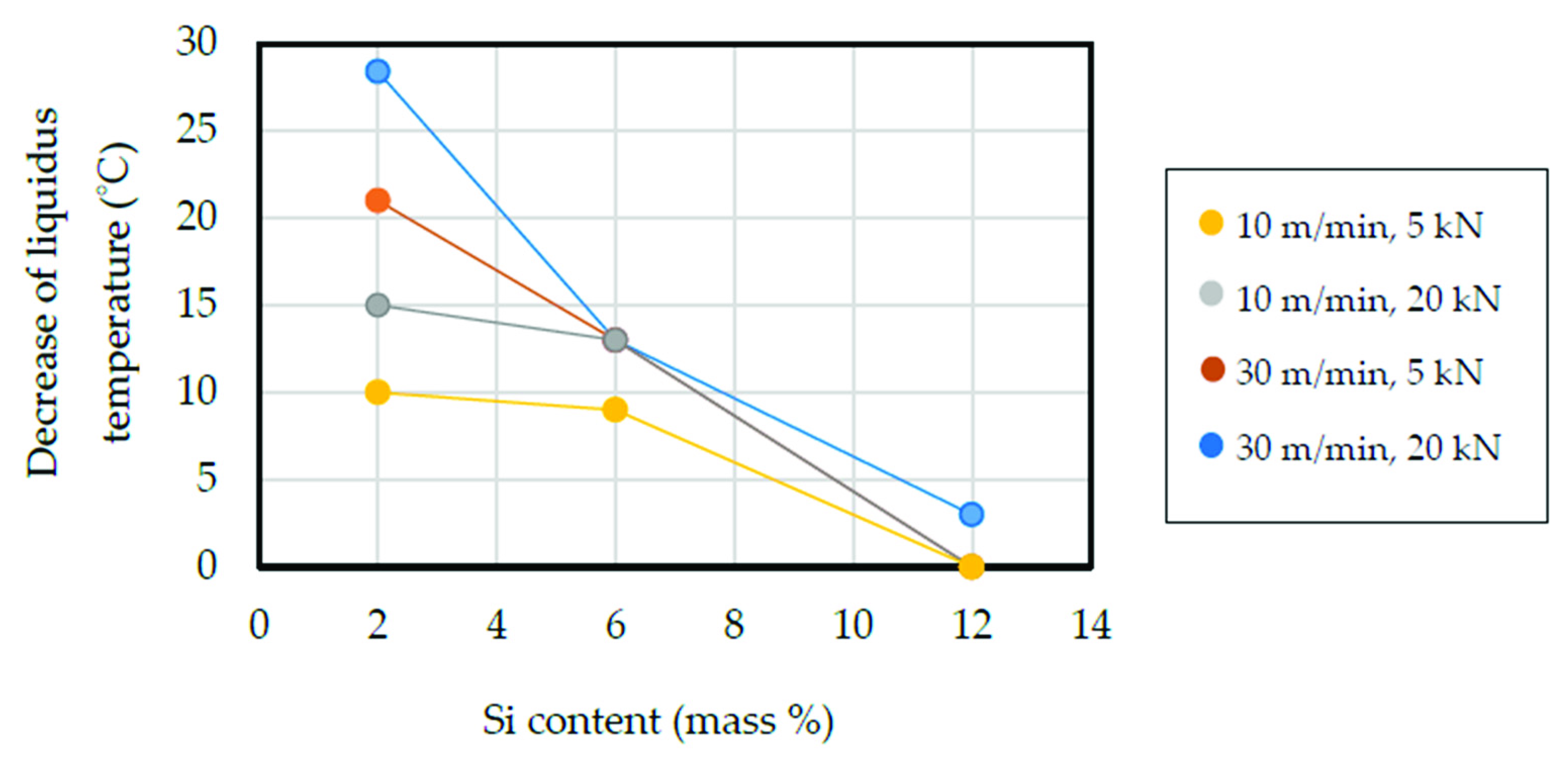
The decrease in the liquidus temperature from that of the equilibrium of the Al-Si alloy was obtained from the cooling curves. The effects of the roll speed, roll load, and Si content on the decrease in the liquidus temperature by supercooling are shown in Figure 6. The decrease (drop) in the liquidus temperature was reduced as the Si content increased from 2% to 6% to 12%. When the Si content was 2%, the liquidus temperature decreased further as the strip thickness increased (see Figure 4). In other words, the liquidus temperature decreased to a greater extent as the roll speed and the roll load increased. The maximum decrease in the liquidus temperature occurred at a roll speed of 30 m/min and roll load of 20 kN, and the minimum decrease occurred at 10 m/min and 5 kN. When the Si content was 6% or 12%, the effect of the roll speed and the roll load on the decrease in the liquidus temperature were smaller than that of the Si content; in other words, the Si content was the dominant factor when the Si content was 6% or 12%. The liquidus temperature only decreased at a roll speed of 30 m/min and roll load of 20 kN when the Si content was 12%.

3.5. Solidification Starting Position

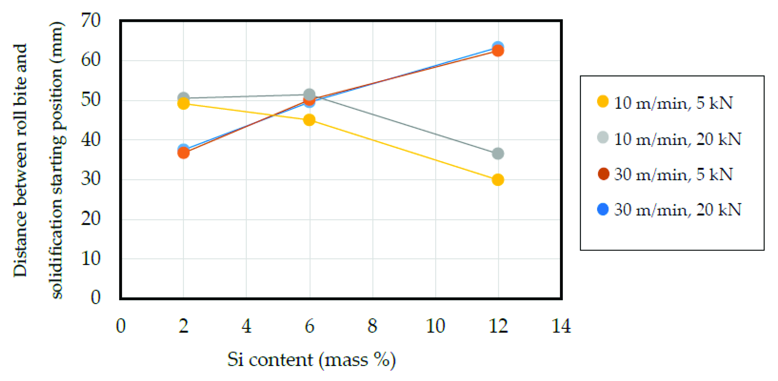
The effects of roll speed, roll load, and Si content on the solidification starting position are shown in Figure 7. The solidification starting position is taken as the distance between the roll bite and the liquidus temperature position. The position of the liquidus temperature shown in Figure 6 was calculated from the roll speed and the time difference between the liquidus temperature and the roll bite. When the roll speed was 30 m/min, the solidification starting position increased (i.e., was farther from the roll bite) as the Si content increased. When the roll speed was 10 m/min, the solidification starting position decreased as the Si content increased. When the roll speed was 30 m/min, the roll load had almost no effect. When the roll speed was 10 m/min, the solidification starting point with 20 kN of roll load was farther from that with 5 kN of roll load when the Si content was 6% or 12%.

3.6. Cooling Rate

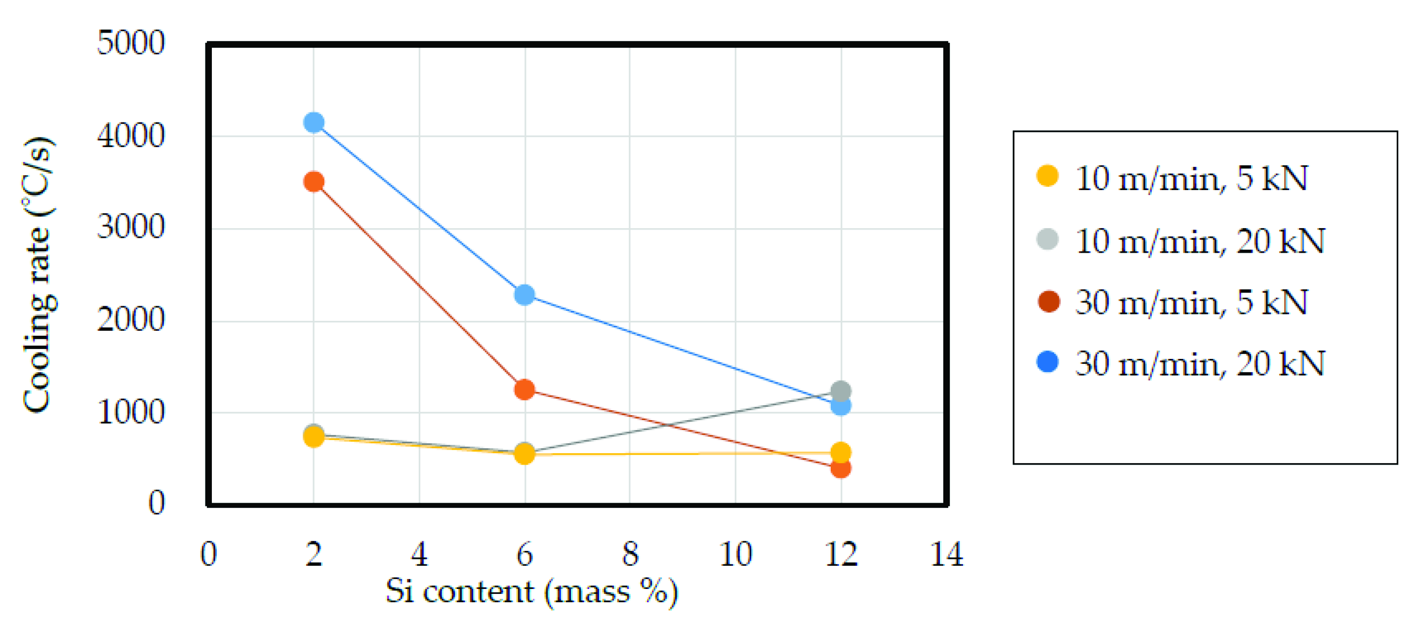
The effects of roll speed, roll load, and Si content on the cooling rate are shown in Figure 8. The cooling rate was obtained from the time and temperature at the liquidus temperature position and the roll bite. When the roll speed was 30 m/min, the cooling rate decreased sharply with increasing Si content. When the roll speed was 30 m/min, the cooling rate at 20 kN of roll load was larger than that at 5 kN of roll load for each Si content. When the roll speed was 10 m/min, the effect of the Si content on the cooling rate was smaller than when the speed was 30 m/min. When the Si content was 2% or 6%, and the roll speed was 10 m/min, the roll load did not affect the cooling rate. When the Si content was 12%, the cooling rate was largest at a roll speed of 10 m/min and a roll load of 20 kN.

3.7. Strip Temperature after Exiting the Rolls

The effects of roll speed, roll load, and Si content on the strip temperature after exiting the rolls is shown in Figure 9. In the VHSTRC, the strip temperature increased after it exited the rolls, as shown in Figure 3. The strip temperature after exiting the roll became higher than the temperature at the roll bite shown in Figure 5. The strip reached the highest temperature after exiting the rolls within 5 s and 2 s at roll speeds of 10 m/min and 30 m/min, respectively. In the CTRCA, the strip temperature decreased after it exited the rolls [24]. All temperatures were lower than the solidus and eutectic lines in the equilibrium diagram, and higher than 480 °C. The effects of the roll speed and the roll load on the strip temperature after it exited the rolls had a general tendency to decrease as the Si content increased.

4. Discussion

4.1. Cooling Curves

The liquidus temperature decreased below the liquidus line in the equilibrium phase diagram, as shown in Figure 3. The solidus temperature was not clearly shown in the cooling curve of the VHSTRC, but the temperature decreased between the rolls and was lowest at the roll bite, after which the strip temperature increased again. It is estimated that the temperature of the strip surface was lower than that of the strip interior, that is, around the thermocouple. The thermocouple was not heated from the outer surface. The aluminum alloy around the thermocouple might have been semisolid at the roll bite due to the supercooling, and the latent heat increased the temperature after the strip exited the rolls when the semisolid metal solidified. The obscurity of the solidus temperature in the cooling curve shows that the aluminum alloy around the thermocouple did not completely solidify before the strip exited the rolls. It became clear that in the VHSTRC, the inside of the strip was semisolid when it exited the rolls. It is proposed that the solidus temperature was lower than the lowest temperature at the valley (“A” in Figure 3) and at the roll bite (Figure 1b), and that the solidus temperature may have been lower than 400 °C, as indicated by Figure 5. Based on this, supercooling decreased the solidus temperature by over 180 °C.

4.2. Solidification Starting Position

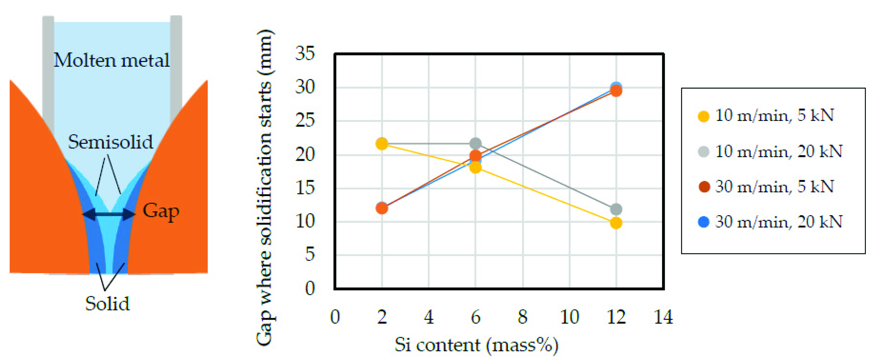
The solidification starting position for the Al-Si alloy was affected by the roll speed and Si content, as shown in Figure 7. To discuss this result, the reduction between the roll gap at the solidification starting position and the roll gap at the roll bite was calculated. The roll gap where the molten metal reached the liquidus temperature was calculated from the solidification starting position and the strip thickness. The solidification starting position gaps are shown in Figure 10.
The reduction between the gap shown in Figure 10 and the strip thickness at the roll bite was calculated, and the results are shown in Figure 11. This reduction is related to the amount of squeezed semisolid metal. The amount of squeezed metal increased as the reduction increased. The quantity of squeezed metal was affected by the Si content. The semisolidus line was reported in previous studies [25,26], which showed that the viscosity in semisolid conditions increases as the Si content increases. When the Si content was 2%, the semisolidus line was near the liquidus line. This meant that most of the semisolid metal had low viscosity.
When the Si content was 2%, the roll load did not affect the quantity of squeezed semisolid metal. The reason for this is that the viscosity of the semisolid metal in the Al-2%Si alloy was low; in other words, the metal was hard, and as a result, the effect of the roll load on the squeezed semisolid metal was small. In Figure 7, the solidification starting position approached the roll bite, and the gap became narrow as the roll speed increased from 10 m/min to 30 m/min. The thickness of the solid layer decreased as the roll speed increased, because the solidification time was shorter. The gaps at both the solidification starting position and at the roll bite decreased when the roll speed increased. In contrast, the roll speed decreased from 30 m/min to 10 m/min, the solidification starting position approached the roll bite, and the gap of the roll bite increased as the strip thickness increased. As a result, the reduction was not influenced by the roll speed when the Si content was 2%.
When roll speed was 30 m/min, the gap of the solidification starting position increased as the Si content increased, as shown in Figure 10. The latent heat of the Al-Si alloy increased as the Si content increased. It is concluded that the solidification starting position approached the roll bite as the Si content increased. The solidification starting position of the Al-12%Si strip cast using a roll speed of 30 m/min was higher than that of the Al-2%Si and Al-6%Si alloys. This practical result means that the position of the semisolid metal for the Al-12%Si alloy was higher than that for Al-2%Si and Al-6%Si alloys.
We then focused on the burrs that occurred at the edge of the strip. The size of the burrs for the Al-Si alloy strip cast using the VHSTRC increased as the Si content increased. The burr size also increased as the roll load increased [27,28]. The viscosity of a semisolid slurry of Al-Si alloy increases as the Si content increases [29]. Based on these empirical experimental results, the following assumptions can be made about the casting of Al-12%Si alloy at a roll speed of 30 m/min. The semisolid metal might have been squeezed upward. Under these conditions, the strip was thin and the roll load was large enough for the semisolid Al-12%Si alloy; as a result, the quantity of squeezed metal increased, and the solidification starting position became higher.
The latent heat of Al-6%Si alloy is larger than that of Al-2%Si alloy. It is estimated that the influence of the viscosity of the semisolid state on the solidification starting position was greater than that of the latent heat in the Al-12%Si alloy compared with the Al-2%Si and Al-6%Si alloys.
The viscosity in the semisolid state of the Al-12%Si alloy was low enough that the squeezing of semisolid metal was not influenced by the roll load at a roll speed of 30 m/min. When the Si content was 12% and the roll speed was 10 m/min, the reduction decreased. The gap between the rolls decreased as the roll speed increased from 10 m/min to 30 m/min, because the thickness of the solidification layer decreased. As a result, the molten metal was easily cooled, and this may have contributed to the upward movement of the solidification starting position. Conversely, a slow roll speed of 10 m/min may have lowered the solidification starting position. The solidification time increased as the roll speed decreased. The solid fraction of the semisolid metal increased as the solidification time increased. This increased the viscosity and decreased the quantity of squeezed metal. When the roll speed was 10 m/min, the roll load was 5 kN, and when the Si content was 12%, the strip became thicker and the quantity of squeezed semisolid metal decreased compared to when a roll load of 20 kN was used. When the roll speed was 10 m/min, the solid fraction of the semisolid was higher than that at 30 m/min, and the squeezed semisolid metal was not influenced by the roll load. When the roll speed and the roll load were lower, the roll gap at the solidification starting position decreased as the roll gap approached the roll bite, and the gap at the roll bite was wide. As a result, the reduction decreased when the roll speed was 10 m/min, the roll load was 5 kN, and the Si content was 12%.
In the Al-6%Si alloy, the latent heat and the viscosity were lower than in the Al-12%Si alloy. Therefore, the difference in the reduction between the roll speeds of 10 m/min and 30 m/min was smaller than in the Al-12%Si alloy.
A comparison of Figure 7 and Figure 10 shows a correlation between the solidification starting position and the reduction. It became clear that the quantity of squeezed metal affected the solidification starting position.

4.3. Decrease in Liquidus Temperature

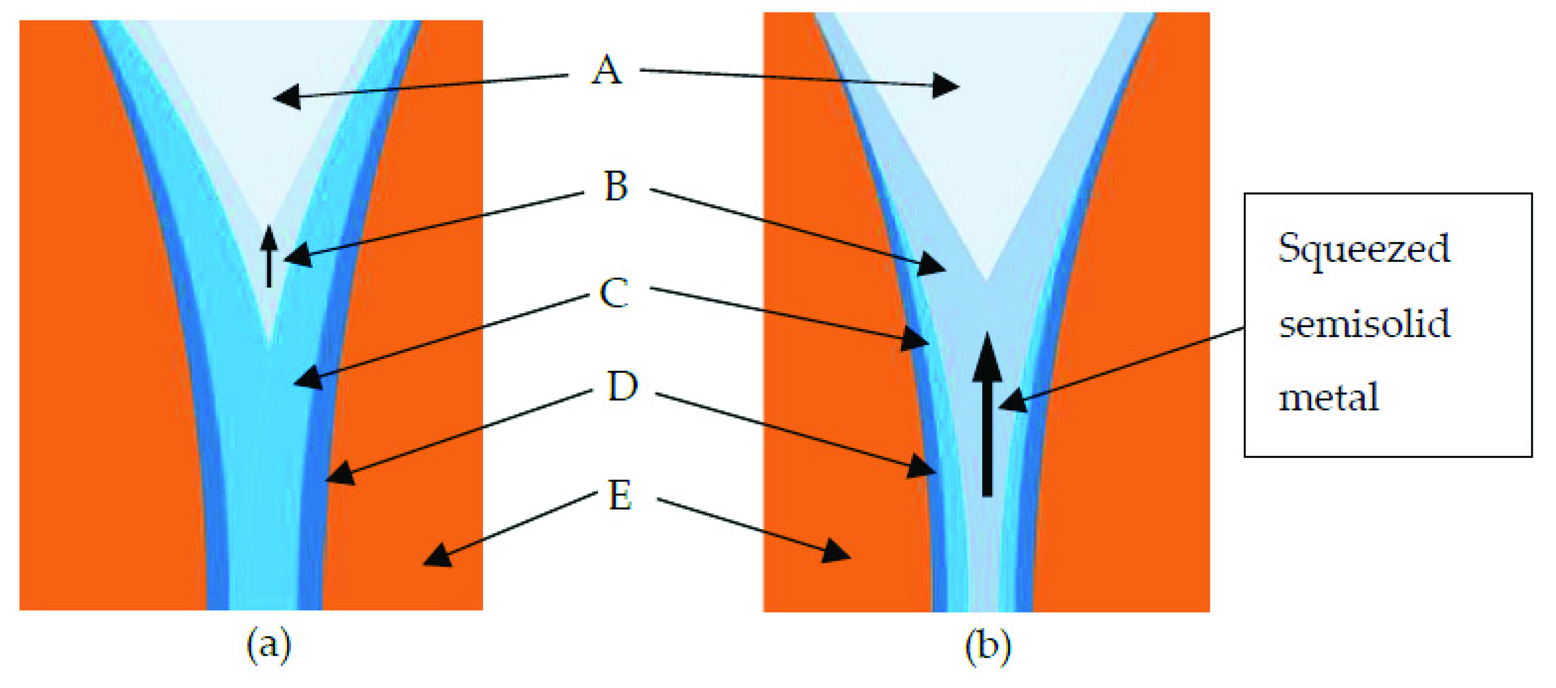
The drop in the liquidus temperature decreased as the Si content increased, as shown in Figure 6. In contrast, the degree of supercooling of an Al-Si alloy increases as the Si content increases when the casting is performed using a metal mold [30]. For the semisolid metal between the rolls in Figure 12a, the semisolidus line is near the liquidus line; in panel (b), the semisolidus line does not exist. Panels (a) and (b) in Figure 12 correspond to the Al-2%Si and Al-12%Si alloys, respectively. In Figure 12a, the fluidity of the semisolid metal is low, and most of it is not squeezed upward. These conditions resemble the fluidity in mold casting. In Figure 12b, the fluidity of the semisolid metal is high, and the semisolid metal is squeezed upward. The squeezed semisolid metal and the molten metal are mixed, and the liquidus temperature probably does not decrease under these conditions. For the VHSTRC, no method to increase the drop in the liquidus line of an aluminum alloy with lower viscosity is currently known.
It is estimated that the solidus temperature was lower than the temperature at the valley (roll bite), and the solidus temperature may have been lower than 400 °C, as judged from Figure 5. Based on this, the decrease in the solidus temperature was estimated to be greater than 180 °C. The solid fraction of the semisolid aluminum alloy increased as the alloy moved toward the roll bite, and the viscosity increased. The alloy was more rapidly cooled as the roll gap decreased, and the solidus temperature decreased sharply.

4.4. Cooling Rate

In the Al-2%Si alloy, the strip temperatures at the roll bite were very similar at different roll speeds and roll loads, as shown in Figure 5. The distance between the solidification starting position and the roll bite was determined almost entirely by the roll speed without influence from the roll load, as shown in the Figure 7. The distances between the solidification starting position and the roll bite for 10 m/min and 30 m/min roll speeds were about 50 mm and 37 mm, respectively. When the roll speed was 10 m/min, it took about four times longer for the strip to move the distance between the solidification starting position and the roll bite than it did with a 30 m/min roll speed. As result, the cooling rate of the strip cast at 10 m/min was a quarter of that for the strip cast at 30 m/min. In this way, the cooling rate was influenced by the roll bite temperature of the strip and by the distance between the solidification position and roll bite. The cooling rate decreased with increased Si content, except for the Al-12%Si cast at a roll speed of 10 m/min and a roll load of 20 kN, as shown in Figure 8. Because the latent heat increases as the Si content increases, there may be a strong correlation between the latent heat and cooling rate. When the Al-12%Si alloy was cast at a roll speed of 10 m/min and a roll load of 20 kN, the temperature at the roll bite was remarkably low. As a result, the cooling rate increased.

4.5. Strip Temperature at Roll Bite

Figure 5 shows the effects of roll speed, roll load, and Si content on the Al-Si strip temperature at the roll bite, which are discussed in this subsection. In Figure 5, when the Si content was 2%, the strip temperature at the roll bite was not affected by the roll speed and roll load. The effects of the roll speed and roll load increased as the Si content increased. When the Si content was 2%, the burr size was very small, which, as explained above, meant that the semisolid metal had very high viscosity. Neither the strip thickness nor the roll load affected the strip temperature. The contact (cooling) time between the roll and solidification layer decreased, as did the strip thickness, as the roll speed increased. Although a thin strip cools more rapidly than a thicker strip, the temperature of the strip cast at a greater roll speed was higher, and the strip was thinner. Therefore, the effect of the roll speed on the strip temperature at the roll bite was very small. When the Si content was 12%, the viscosity of the semisolid alloy was very high. Therefore, the semisolid metal was squeezed toward the edges and upward. This meant that the semisolid metal, which had a higher temperature, was squeezed farther upward, and the strip thickness decreased. As a result, the strip temperature decreased as the roll load increased. When the roll speed decreased, the solidification time increased, and the strip temperature decreased. Therefore, when the roll speed was 10 m/min and the roll load was 20 kN, the temperature at the roll bite decreased sharply. When the roll load was 5 kN and the roll speed was 30 m/min, the strip temperature at the roll bite increased because the strip temperature increased and the quantity of squeezed semisolid metal decreased.

4.6. Strip Temperature after Exiting Rolls

The temperature of the strip after it exited the rolls (Figure 9) was higher than the strip temperature at the roll bite (Figure 5) for the same Si content and casting conditions. It is estimated that the inside of the strip was not completely solidified (semisolid), and that the strip temperature was increased by the latent heat of the semisolid metal. The location of the thermocouple in the band zone shows that this zone was not completely solidified when the strip exited the rolls. The band zone formed due to its slower solidification. The cause of the formation of globular crystals is estimated as follows. The secondary dendrite arms of the rapidly solidified equiaxial dendrites in the solidified layers were separated by heating from the latent heat when the band zone solidified, and the secondary dendrite arms became globular, similar to a characteristic of thixocasting [31]. Increasing the roll load may be useful for completely solidifying the inside of the strip. However, a copper alloy roll is not hard, and increasing the roll load will decrease its service life. Thus, the secondary cooling of the strip after it exits the rolls may be appropriate.
The tendencies of the strip temperature at the roll bite (Figure 5) and the strip temperature after it exited the rolls (Figure 9) were different. The strip cooled in air after exiting the rolls, and the degree of cooling was extremely low. The strip temperature after it exited the rolls likely increased due to the latent heat of the semisolid metal, which mainly existed in the band zone. The latent heat of the Al-Si alloy increased as the Si content increased. The amount of latent heat is determined by the quantity and temperature of the semisolid metal. The band zone was cooled by the solidification layers on both sides. The cooling ability of the solidification layers was influenced by the average temperature, the temperature distribution, and the strip thickness. It is necessary to consider these factors comprehensively to discuss the strip temperature after it exited the rolls. It may be useful to measure the temperature of the strip surface in contact with the roll by inserting the thermocouple between the strip and the roll.
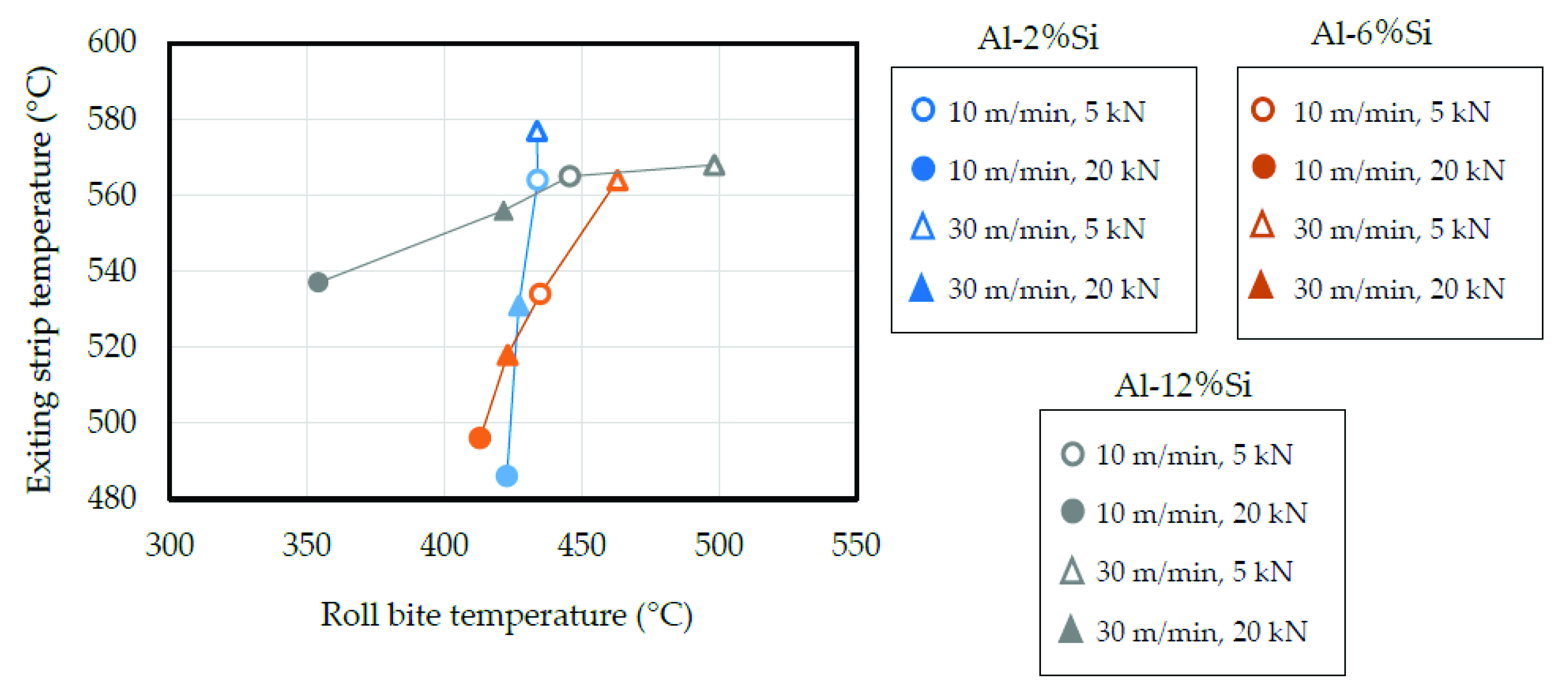
The relationship between the strip temperature at the roll bite (shown in Figure 5) and after exiting the roll (shown in Figure 9) is represented in Figure 13. This figure indicates that the strip temperature after exiting the rolls increased as the strip temperature at the roll bite increased. The temperature increase rate after the strip exited the rolls increased as the Si content decreased.

5. Conclusions

The properties of the casting process for an aluminum alloy strip cast by a VHSTRC were clarified in this paper. A 0.1 mm diameter K-type thermocouple was inserted into a strip during casting to achieve the research objectives. The effects of the roll speed, roll load, and Si content on the cooling rate, liquidus temperature, solidification starting position, strip temperature at the roll bite, and strip temperature after exiting the rolls were investigated. The findings of this study are as follows:
(1)
The Al-Si strip temperature after exiting the rolls increased to exceed the strip temperature at the roll bite.
(2)
The strip interior was not yet solidified when the strip exited the rolls.
(3)
The degree of supercooling of the liquidus temperature was lower than 30 °C, and that of the solidus temperature was higher than 180 °C. The supercooling of the liquidus temperature of the Al-Si alloy decreased as the Si content increased.
(4)
The strip temperature at the roll bite decreased as the roll speed decreased and the roll load increased.
(5)
The cooling rate increased as the Si content decreased, the roll speed increased, and the roll load increased.
Thus, the properties of the VHSTRC were elucidated.
It is proposed based on the results of this study that the interior of a strip cast by a VHSTRC has not completely solidified. In the practical application of a VHSTRC, secondary cooling to solidify the semisolid metal may be useful for preventing precipitation in the solid solution and the growth of grains. The mechanical and physical properties may be improved by secondary cooling. Spraying a cooling gas/water or passing the strip through a water bath may be appropriate methods for the secondary cooling of the as-cast strip. In-line hot rolling may be useful for solidifying the semisolid metal, eliminating or improving the porosity and segregation, and improving the mechanical properties.
The effect of roll size was not clarified by this study. The width of the band zone may have gradually decreased as the radius of the curvature increased. Thus, the roll curvature may influence the flow of the semisolid metal. As a result, the roll size may affect the cooling rate and decrease the solidus temperature.

Author Contributions

Conceptualization, T.H.; methodology, T.H.; validation, T.H. and Y.K.; formal analysis, T.H.; investigation, T.H. and Y.K.; resources, T.H. and Y.K.; data curation, T.H.; writing—original draft preparation, T.H.; writing—review and editing, T.H.; visualization, T.H.; supervision, T.H.; project administration, T.H.; funding acquisition, T.H. All authors have read and agreed to the published version of the manuscript.

Funding

This research was funded by the SUZUKI FOUNDATION and the AMADA Foundation (AF-2018027-B3).

Institutional Review Board Statement

Not applicable.

Informed Consent Statement

Not applicable.

Conflicts of Interest

The authors declare no conflict of interest.

References

  1. Cook, R.; Cook, P.G.; Thomas, P.M.; Edmonds, D.V.; Hunt, J.D. Development of the twin-roll casting process. J. Mater. Process. Technol. 1995, 55, 76–84. [Google Scholar] [CrossRef]
  2. Taraglio, B.; Romanowski, C. Thin-gage/high-speed roll casting technology for foil production. Light Met. (TMS) 1995, 1165–1182. [Google Scholar]
  3. Cortes, M. Pechiney-Jumbo 3 CM the new demands of thin strip casting. Light Met. (TMS) 1995, 1161–1164. [Google Scholar]
  4. Nussbaum, A.I. Three-state-of-the-art Thin -gage high-speed roll caster for aluminum alloy sheet products. Light Met. Age 1996, 12, 8–19. [Google Scholar]
  5. Nussbaum, A.I. Three-state-of-the-art Thin-gage high-speed roll caster for aluminum alloy sheet products Part III. Light Met. Age 1997, 55, 34–39. [Google Scholar]
  6. Thomas, P.M.; Grocock, P.G.; Bouzendorffer, J.M. Dynamic strip caster- an update on the operation of the roll caster at Eurofoil. Melall. Plant Technol. Int. 1997, 20, 44–52. [Google Scholar]
  7. Hamer, S.; Romanowski, C.; Taraglio, B. Continuous casting and rolling of aluminum: Analysis of capacities, Product ranges and technology. Light Met. Age 2002, 60, 6–17. [Google Scholar]
  8. Gras, C.; Meredith, N.; Hunt, J.D. Microdefects for mation during the roll casting of Al-Mg-Mn aluminum alloys. J. Mater. Process. Technol. 2005, 167, 62–72. [Google Scholar] [CrossRef]
  9. Daaland, O.; Espedal, A.B.; Nedreberg, M.L.; Alvestad, I. Thin gage twin-roll casting, process capabilities and product quality. Light Met. (TMS) 2016, 3, 989–996. [Google Scholar] [CrossRef]
  10. Li, Y.; He, C.; Li, J.; Wang, Z.; Wu, D.; Xu, G. A novel approach to improve the microstructure and mechanical properties of Al-Mg-Si aluminum alloys during twin-roll casting. Metals 2020, 13, 1713. [Google Scholar] [CrossRef] [Green Version]
  11. Xu, Z.; Wang, S.; Wang, H.; Song, H.; Li, S.; Chen, X. Effect of cooling rate on Microstructure and properties of twin-roll casting 6061 aluminum alloy sheet. Metals 2020, 10, 1168. [Google Scholar] [CrossRef]
  12. Haga, T.; Takahashi, K.; Ikawa, M.; Watari, H. A vertical type twin roll caster for aluminum alloy strip. J. Mater. Proc. Technol. 2003, 140, 610–615. [Google Scholar] [CrossRef]
  13. Haga, T.; Suzuki, S. Study on high-speed twin roll caster for aluminum alloys. J. Mater. Proc. Technol. 2003, 143–144, 895–900. [Google Scholar] [CrossRef]
  14. Haga, T.; Takahashi, K.; Ikawa, M.; Watari, H. Twin roll casting of aluminum alloy strips. J. Mater. Proc. Technol. 2004, 153, 42–47. [Google Scholar] [CrossRef]
  15. Haga, T. High Speed Roll Caster for Aluminum Alloy. Metals 2021, 11, 520. [Google Scholar] [CrossRef]
  16. Nakamura, R.; Haga, T.; Kumai, S.; Watari, H. Casting of aluminum alloy clad strip using a vertical type tandem twin roll caster. Adv. Mar. Res. 2010, 97–101, 1053–1056. [Google Scholar] [CrossRef]
  17. Haga, T.; Kumai, S.; Watari, H. Casting of Al-25%Si strip using a vertical type twin roll caster. Adv. Mar. Res. 2011, 239–242, 1944–1947. [Google Scholar] [CrossRef]
  18. Haga, T.; Ikawa, M.; Watari, H.; Suzuki, K.; Kumai, S. High-speed twin roll casting of thin aluminum alloy strips containing Fe impurities. Mater. Trans. 2005, 46, 2596–2601. [Google Scholar] [CrossRef] [Green Version]
  19. Harada, Y.; Jiang, N.; Kumai, S. Mechanical Properties of Cold-Rolled and Annealed Al-12%Mg alloy Sheet with High Mg Solid Solubility Fabricated from Vertical-Type High-Speed Twin Roll Cast Strip. Mater. Trans. 2019, 60, 2435–2441. [Google Scholar] [CrossRef]
  20. Kim, M.S.; Kim, H.E.; Kim, S.H.; Kumai, S. Role of Roll Separating Force in High-Speed Twin-Roll Casting of Aluminum Alloys. Metals 2019, 9, 645. [Google Scholar] [CrossRef] [Green Version]
  21. Kim, M.S.; Kim, H.E.; Kumai, S. Direct Temperature Measurement of Al-2mass%Si Alloys Strips during High-Speed Twin-Roll Casting and Its Applications in Determining Melt/Roll Heat Transfer Coefficient for Simulation. Mater. Trans. 2017, 58, 967–970. [Google Scholar] [CrossRef] [Green Version]
  22. Song, R.; Harada, Y.; Kumai, S. Influence of Cooling Rate on Primary Particle Solute Distribution in High-Speed Twin-Roll Cast Al-Mn Based Alloy Strip. Mater. Trans. 2018, 59, 110–116. [Google Scholar] [CrossRef] [Green Version]
  23. Itamura, M.; Yamamoto, N. Effects of Silicon Content on Latent Heat of Al-Si Alloys. J. Jpn. Foundry Eng. Soc. 1996, 66, 493–498. [Google Scholar] [CrossRef]
  24. Sugiyama, M.; Fukusako, T.; Sato, A. Direct-rolling of Molten Pure Aluminum. J. Jpn. Inst. Met. Mater. 1968, 32, 731–735. [Google Scholar] [CrossRef] [Green Version]
  25. Isobe, T.; Kubota, M.; Kitaoka, M. Criteria for Subdivision of Liquid-Solid Zone in Aluminum Alloys on the Basis of Contraction and Measurements. J. JFS 1978, 50, 235–239. [Google Scholar] [CrossRef]
  26. Isobe, T.; Kubota, M.; Kitaoka, M. Influence of Semi-solid Temperature Range and the Rate Influence in Strength during the Solidification Process on the Hot Tearing of Cast Aluminum Alloys. J. JFS 1978, 50, 425–430. [Google Scholar] [CrossRef]
  27. Haga, T.; Yamashiki, T.; Watari, H.; Nishida, S. Investigation of Burr on Strips Cast by Vertical-Type High-Speed Twin Roll Caster. Key Eng. Mater. 2020, 831, 40–45. [Google Scholar] [CrossRef]
  28. Haga, T.; Yamashiki, T.; Watari, H.; Nishida, S. Burr Formation in Casting Using Vertical-Type High-Speed Twin-Roll. Key Eng. Mater. 2020, 846, 146–151. [Google Scholar] [CrossRef]
  29. Miwa, K.; Ichikawa, R. Apparent Viscosity and Structure in Al-Si Alloys Partially Solidified under Stirring. J. Jpn. Inst. Met. 1981, 45, 853–859. [Google Scholar] [CrossRef] [Green Version]
  30. Ichikawa, R.; Ikeda, T.; Ohashi, T. Effects of Cooling Rate and Supercooling on the Solidified Structure of Various Aluminum alloys. J. JFS 1974, 46, 25–35. [Google Scholar] [CrossRef]
  31. Haga, T.; Kapranos, P. Thixoforming of laminate made from semisolid cast strips. J. Mater. Process. Technol. 2004, 157, 508–512. [Google Scholar] [CrossRef]
Figure 1. Schematic showing how the thermocouple was inserted into the molten metal pool and incorporated into the strip during casting: (a) rolls are rotating at a designated speed, and a lead wire is set between the rolls; (b) strip drags the lead wire; (c) thermocouple passes through the molten metal pool and is incorporated into the strip. (d) Photograph of (b) from overhead.
Metals 12 01169 g001
Figure 2. (a) Tip of thermocouple and lead wire; (b) thermocouple inserted into strip.
Metals 12 01169 g002
Figure 3. Cooling curves (time–temperature diagrams) for aluminum alloys cast using a VHSTRC and an insulated mold. Left and right sides of each panel are the cooling curves for the VHSTRC and the insulated mold, respectively. The roll speed was 30 m/min and roll load was 20 kN for casting using a VHSTRC. Dashed lines show the liquidus and solidus temperatures attained using the insulated mold.
Metals 12 01169 g003
Figure 4. Effects of roll speed, roll load, and Si content on Al-Si strip thickness. Roll speed: 10 m/min and 30 m/min; roll load: 5 kN and 20 kN; Si content: 2%, 6%, and 12%.
Metals 12 01169 g004
Figure 5. Effects of roll speed, roll load, and Si content on strip temperature at roll bite. Roll speed: 10 m/min and 30 m/min; roll load: 5 kN and 20 kN; Si content: 2%, 6%, and 12%.
Metals 12 01169 g005
Figure 6. Effects of roll speed, roll load, and Si content on decrease in the liquidus temperature of Al-Si alloy from equilibrium. Roll speed: 10 m/min and 30 m/min; roll load: 5 kN and 20 kN; Si content: 2%, 6%, and 12%.
Metals 12 01169 g006
Figure 7. Effects of roll speed, roll load, and Si content on solidification starting position of Al-Si. Roll speed: 10 m/min and 30 m/min; roll load: 5 kN and 20 kN; Si content: 2%, 6%, and 12%.
Metals 12 01169 g007
Figure 8. Effects of roll speed, roll load, and Si content on cooling rate for Al-Si alloy. Roll speed: 10 m/min and 30 m/min; roll load: 5 kN and 20 kN; Si content: 2%, 6%, and 12%.
Metals 12 01169 g008
Figure 9. Effects of roll speed, roll load, and Si content on Al-Si strip temperature after exiting the rolls. The strip temperature increased and decreased after exiting the rolls. This figure shows the highest temperatures. Roll speed: 10 m/min and 30 m/min; roll load: 5 kN and 20 kN; Si content: 2%, 6%, and 12%.
Metals 12 01169 g009
Figure 10. Gap where solidification started, as calculated from solidification starting positions and strip thicknesses. Roll speed: 10 m/min and 30 m/min; roll load: 5 kN and 20 kN; Si content: 2%, 6%, and 12%.
Metals 12 01169 g010
Figure 11. Reduction calculated from solidification starting positions and strip thicknesses. Roll speed: 10 m/min and 30 m/min; roll load: 5 kN and 20 kN; Si content: 2%, 6%, and 12%.
Metals 12 01169 g011
Figure 12. Schematic showing aluminum alloy between rolls: (a) semisolidus line is near the liquidus line; (b) semi-solidus line does not exist. A: molten metal, B: semisolid metal with poor viscosity, C: semisolid metal with excellent flowabiliy, D: solidified metal, E: copper roll.
Metals 12 01169 g012
Figure 13. Relationship between roll bite temperature and exiting strip temperature. Roll speed: 10 and 30 m/min; roll load: 5 and 20 kN; Si content: 2%, 6%, and 12%.
Metals 12 01169 g013
Table 1. Chemical composition of Al-Si alloys (mass%).
AlloySiFeCuMnMgCrZnTiNi
Al-2%Si2.040.11<0.01<0.01<0.01< 0.01<0.010.010.01
Al-6%Si6.000.13<0.01<0.010.010.01<0.010.010.01
Al-12%Si12.100.17<0.01<0.010.010.01<0.010.01<0.01
Publisher’s Note: MDPI stays neutral with regard to jurisdictional claims in published maps and institutional affiliations.