Article

Effect of Axial Normal Stress and Bending Moment between Contact and Non-Contact Zone on Forming Accuracy for Flexible Stretch Bending Formation

1
School of Mechanical and Vehicle Engineering, Changchun University, Changchun 130022, China
2
College of Materials Science and Engineering, Jilin University, Changchun 130025, China
3
Chongqing Research Institute, Jilin University, Chongqing 401123, China
4
School of Computer Science and Technology, Changchun University, Changchun 130022, China
*
Author to whom correspondence should be addressed.
Metals 2022, 12(7), 1168; https://doi.org/10.3390/met12071168
Submission received: 10 June 2022 / Revised: 27 June 2022 / Accepted: 7 July 2022 / Published: 8 July 2022

Abstract

:
Flexible 3D stretch bending (FSB) is a technology that uses multi-point molds instead of traditional integral molds to bend and deform profiles. Since the position of a multi-point mold can be adjusted in the horizontal and vertical directions, a set of molds can be used to form profile products with different contour structures. Due to the contact area and non-contact area between the multi-point mold and the surface of the profile, the forming accuracy of different areas is different. Thus, the axial normal stress and bending moment of the contact zone and non-contact zone between the profile and roller dies are studied in this article. By simulating the change in axial normal stress at the same position in the middle of a web along the axial direction, it is found that the axial normal stress shows little difference in the contact zone and non-contact zone. The value of axial normal stress in the non-contact zone is relatively stable, and there is a small increase on the side near the clamp. By simulating the axial normal stress of different cross-sections in the middle areas of three groups of webs, it is found that there is a linear relationship between the axial normal stress and the distance from inner curved surface. The bending moment of the profile in the contact zone is obviously greater than that in the non-contact zone, and the bending moment gradually decreases to near zero from the contact zone to the non-contact zone. The bending deformation of the profile in the contact zone is obviously greater than that in the non-contact zone, which results in the deviation between simulated bending displacement and theoretical bending displacement in the contact zone and non-contact zone.

1. Introduction

In recent years, with the rapid development of modern industrialization, the demand for 3D aluminum profile components in automobile, high-speed rail, aircraft and other manufacturing industries is increasing. The traditional 2D stretch bending process has been unable to meet the industrial demand, and 3D stretch bending has begun to develop [1,2,3,4,5,6].
FSB is a combination of flexible advanced manufacturing and the 3D bending of profiles. In order to optimize the rapid production and flexible manufacturing of this bending process, many scholars have carried out a lot of research on the formation of defects such as springback, wrinkling, section distortion and asymmetric section distortion caused by FSB [7,8,9,10,11,12,13]. However, up to now, there are still few studies on the multi-point stretch bending process of profiles, and there are still a series of problems that need to be studied urgently [14]. The distribution of bending moment is very important to the accuracy of bending. Miyazaki K. et al. studied the influence of bending moment on the wall thickness reduction in pipes [15]. Tang N.C. proposed some practical formulas to explain the bending moment and other problems existing in bending pipes, which were verified by experiments [16]. Daniel I.M. et al. carried out bending moment and shearing load tests on composite sandwich beams and observed their failure modes [17]. Hopperstad O.S. used the finite element analysis method to study the stretching and bending process of aluminum profiles and analyzed the strain hardening, yield stress and plastic anisotropy of aluminum alloy materials during the forming process [18] using numerical simulation software. LS-DYNA was used to build three models of anisotropic plasticity with different yield criteria (Hill, Harlat, Karafillis and Boyce), but they all have non-linear isotropic strain hardening phenomena [19].
In FSB technology, multi-point molds replace traditional molds. Due to the structure characteristics of FSB dies, there are contact and non-contact zones between the profile and the dies. Owing to the discontinuity formation of profiles, the difference in stress and bending moment between the contact zone and the non-contact zone directly affects the formation quality of the profile. In this paper, based on ABAQUS software (Dassault, Providence, RI, USA), a numerical simulation and an experimental study on the multi-point stretch bending of L-shaped aluminum profiles are carried out, the change law in axial normal stress and the bending moment in the contact zone and non-contact zone between the profile and roller dies are explored, and the influence of the difference in bending moment between the contact zone and non-contact zone on profile deformation is studied. Based on the research results, operators can make more precise adjustments to the multi-point mold position to compensate for the adverse effects of formation discontinuities.

2. The Finite Element Simulation of FSB

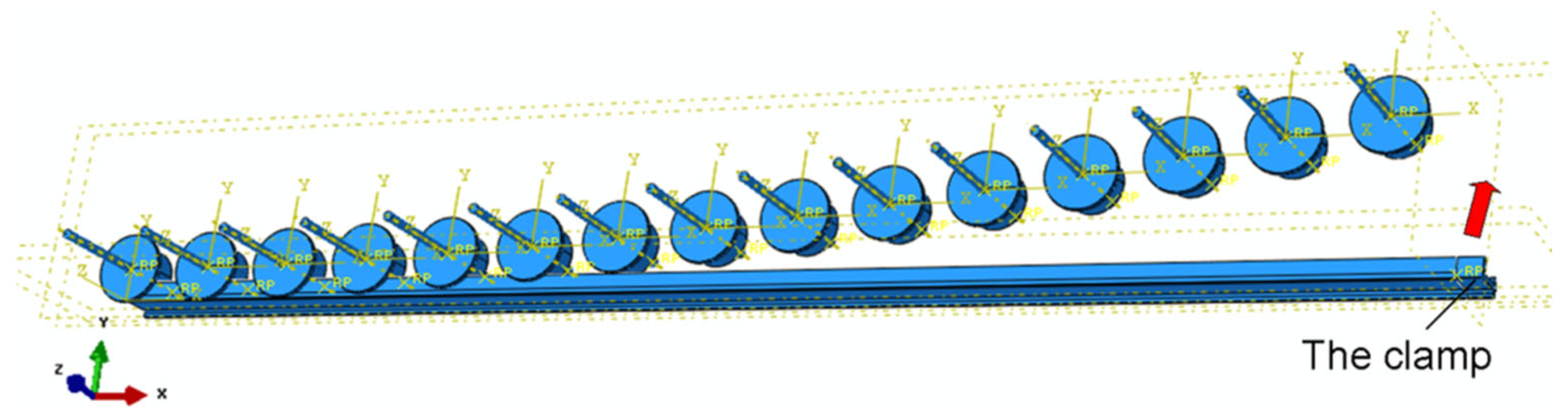
2.1. The FSB Process

FSB technology is used to separate whole stretch bending die into a series of regularly arranged flexible fundamental units (FFUs) [18] which can be adjusted independently. By precisely controlling the FFUs, the forming surface of a profile is constructed. Compared with traditional stretch bending die, it is more flexible and efficient. Figure 1 shows the schematic diagram of the overall die stretch bending formation and FSB formation.
The structural diagram of FSB equipment is shown in Figure 2. Each roller die is independently regulated and can move and rotate freely in horizontal and vertical directions, and the tangential circle of each roller die constitutes the target envelope surface. Because of the small contact area between the roller die and profile, the FSB has more flexibility and diversity. The forming process of FSB is as follows:
(1)
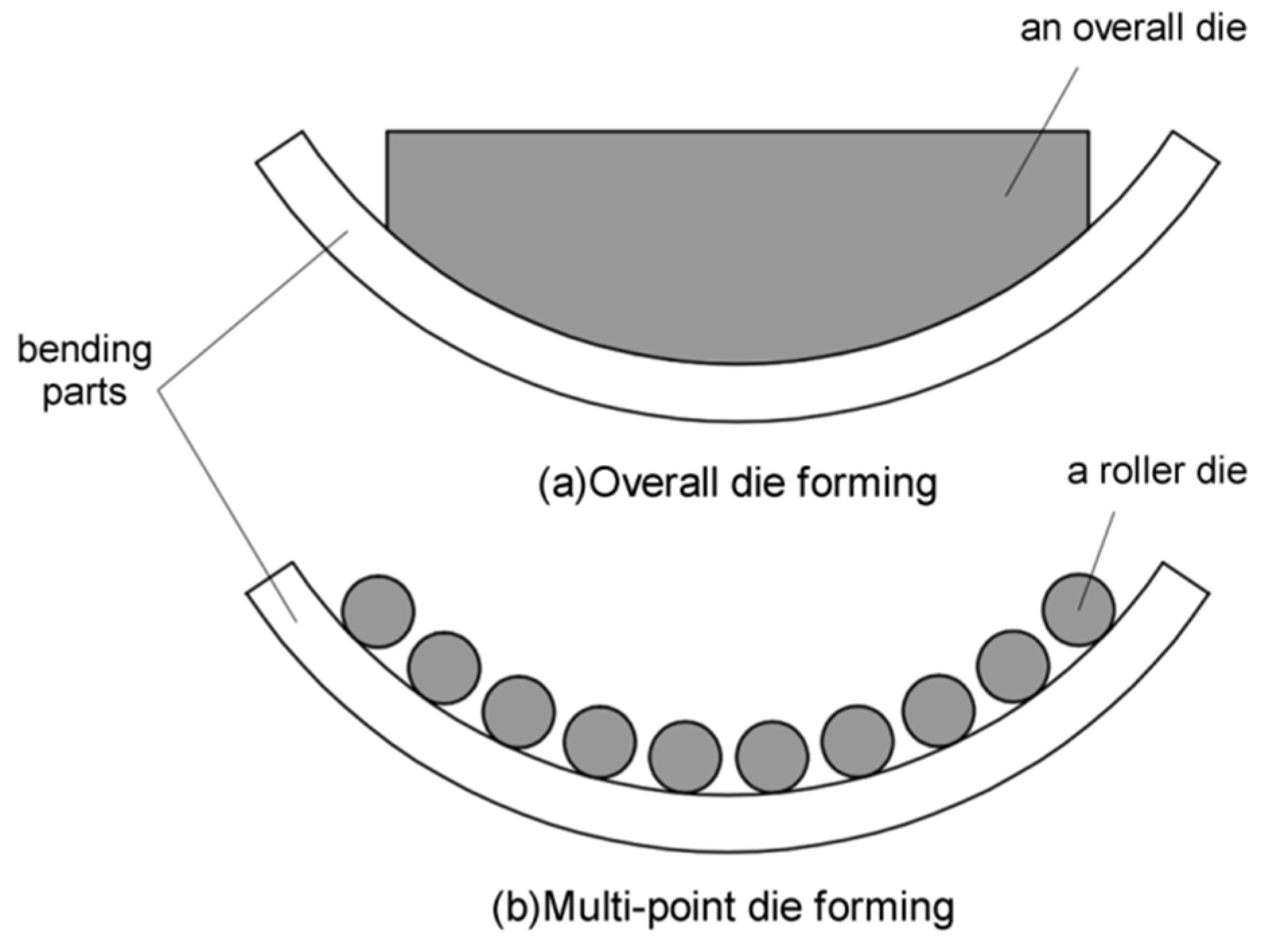
Adjust the position of the dies: In a multi-point die set, each die can be moved in vertical and horizontal positions. According to the shape of the target part, the position of each mold can be adjusted one by one. Thus, the whole set of multi-point molds can form the shape of the forming profile;
(2)
Torsion deformation: In order to adapt to the spatial position of the multi-point mold, before the profile is attached to the mold, the clamp drives the profile to rotate at an angle;
(3)
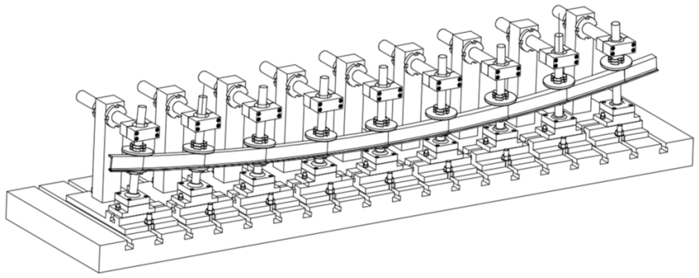
Stretch bending formation: One end of the profile is fixed by a clamp. At the same time, under the traction of the other end of the clamp, the profile is driven to complete the horizontal movement and vertical lifting. Make the profile fix the multi-point molds point by point to complete the space formation;
(4)
Clamp removing: After formation, the profile is removed from the mold to complete the preparation.

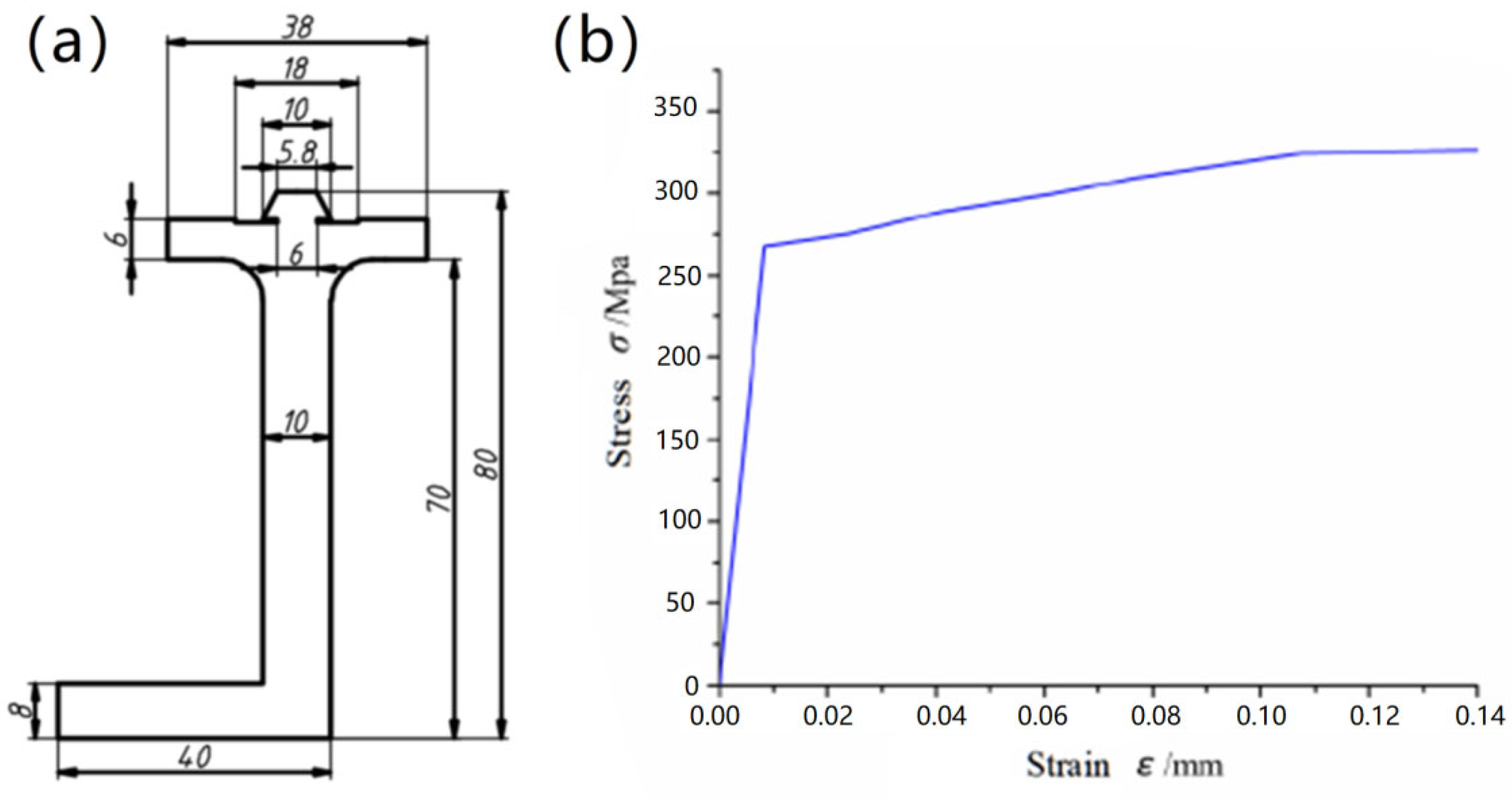
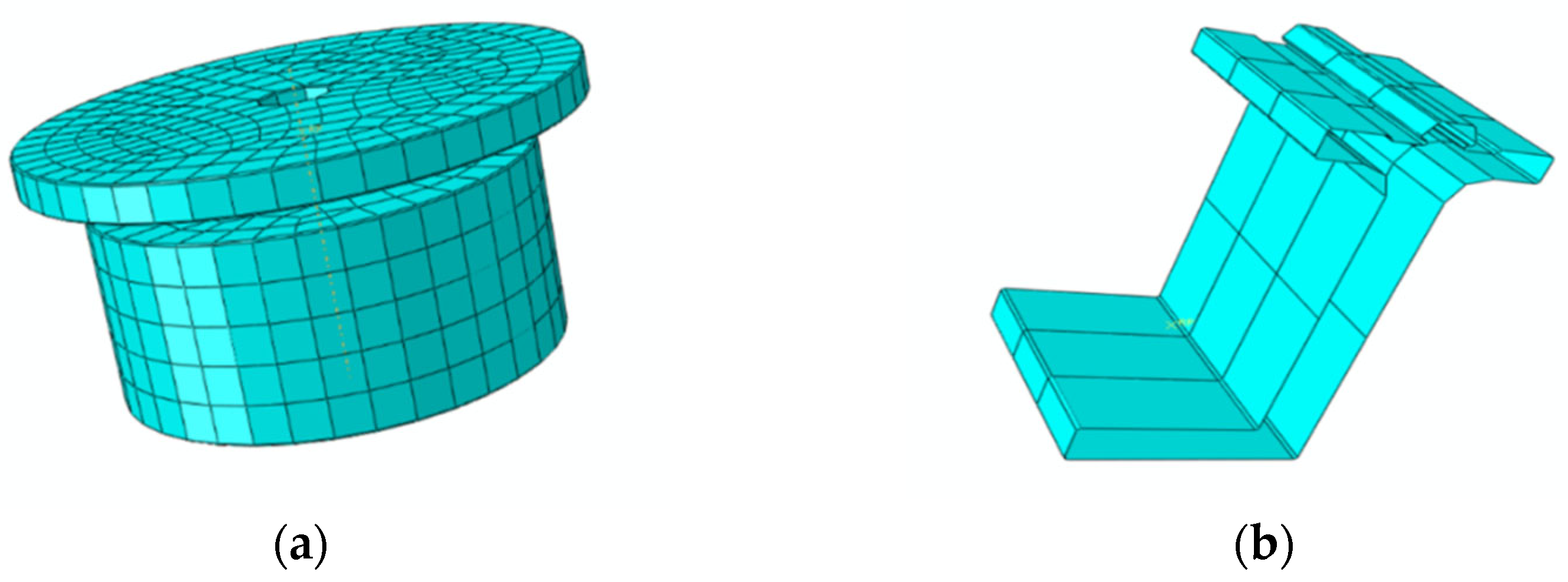
2.2. Model Parameters

In this paper, finite element analysis of the horizontal stretch bending process of an L-shaped profile was carried out by using the finite element software ABAQUS. (Dassault, Providence, RI, USA) The profile material was aluminum profile 6005A. The shape and size parameters are shown in Figure 3, and the material parameters are shown in Table 1. The overall length of the profile was L = 6000 mm. The bilinear elastic–plastic hardening curve, power hardening curve and true stress–strain curve of 6005A pipe were used for simulation analysis, and the parameters of the three models were input into the ABAQUS (Dassault, Providence, RI, USA). The simulation analysis results show that when the true stress–strain relationship curve is used as the material model, the simulation analysis results are the closest to the experimental results. The accuracy of the input bilinear hardening material model analysis results is higher than that of the power hardening material model.

2.3. Model Parameters

In this paper, we used ABAQUS/Explicit (Dassault, Providence, RI, USA) explicitly simulate the FSB process of the profile. The finite element models included the profile, the roller die, the bracket and the clamp. The finite element model components, element types, number of elements and number of nodes are shown as Table 2. In order to reduce the simulation time, a 1/2 profile was selected for modeling. The clamp and the die used discrete rigid body shells that meant that deformation did not need to be calculated, and the profile used deformable solids. The coefficient of friction between the profile and multi-point mold was 0.1. The element type of the profile was a 3D deformable element, and the profile was distorted during deformation, so the eight-node linear hexahedral element C3D8R was used to reduce the integral element. The roller die, the bracket and the clamp selected a rigid body element, and no deformation occurred in the deformation of the profile, so the four-node, three-dimensional bilinear rigid body quadrilateral R3D4 was used. The roller die and clamp are shown in Figure 4. The distance between each roller die along the x-axis was 200 mm, the bending angle of the profile was 10 degrees, and the assembly of each part is shown in Figure 5 (in this research, the position displayed by the abscissa was the multi-point mold position).

2.4. Design of Clamp Track

In the process of stretch bending, the movement of the profile is driven by the clamp, so the track of the clamp is very important in the accuracy of finite element analysis. In the finite element simulation, we controlled the track of the clamp by controlling the displacement of the clamp. By describing several special positions of the clamp, the movement track of the clamp was constrained. We chose the position of the clamp when the profile was in contact with the die as the special position. The calculation of several positions of the clamp is shown in Figure 6.
In the process of stretch bending, the profile not only has horizontal bending, but also has axial stretching. In order to ensure the forming quality, the axial stretching amount must be controlled each time, so the calculation of clamp track is more complex. First, we calculated the position of the clamp when the profile was not stretched. From Figure 6, the x-axis displacement Δxi and the y-axis displacement Δyi of the clamp movement to each special position can be calculated, where i is the die number from left to right, i = 1, 2, 3, ..., 15:
Δxi = L − (R × sinαi + (L − R × αi) × cosαi)
Δyi = R × (1 − cosαi) + (L − R × αi) × sinαi
where L is the length of the profile, R is the bending radius, and αi is the angle between the “i” die and the first die.
In this study, according to the formation characteristics of the product and previous experience, the displacement of every two multi-point molds was 30 mm, multiplied by a certain proportion. Additionally, the proportion was defined as Δxi/Δx15. We used Δxi/Δx15 × 30 as the length of each stretch of the profile. In this way, the x-axis displacement Δx′i and the y-axis displacement Δy′i of the clamp were calculated as follows.
Δx′i = L − (R × sinαi + (L + Δxi/Δx15 × 30 − R × αi) × cosαi)
Δy′i = R × (1 − cosαi) + (L + Δxi/Δx15 × 30 −R × αi) × sinαi

3. The Experiments and Numerical Simulation of FSB Process

In the process of deformation, the difference in axial normal stress and bending moment between the contact zone and non-contact zone will affect the forming accuracy of profile, and it has important significance in the research of springback. In this paper, the axial normal stress and bending moment in the middle area of the web were studied, and their effects on the bending deformation of the profile are also discussed here.

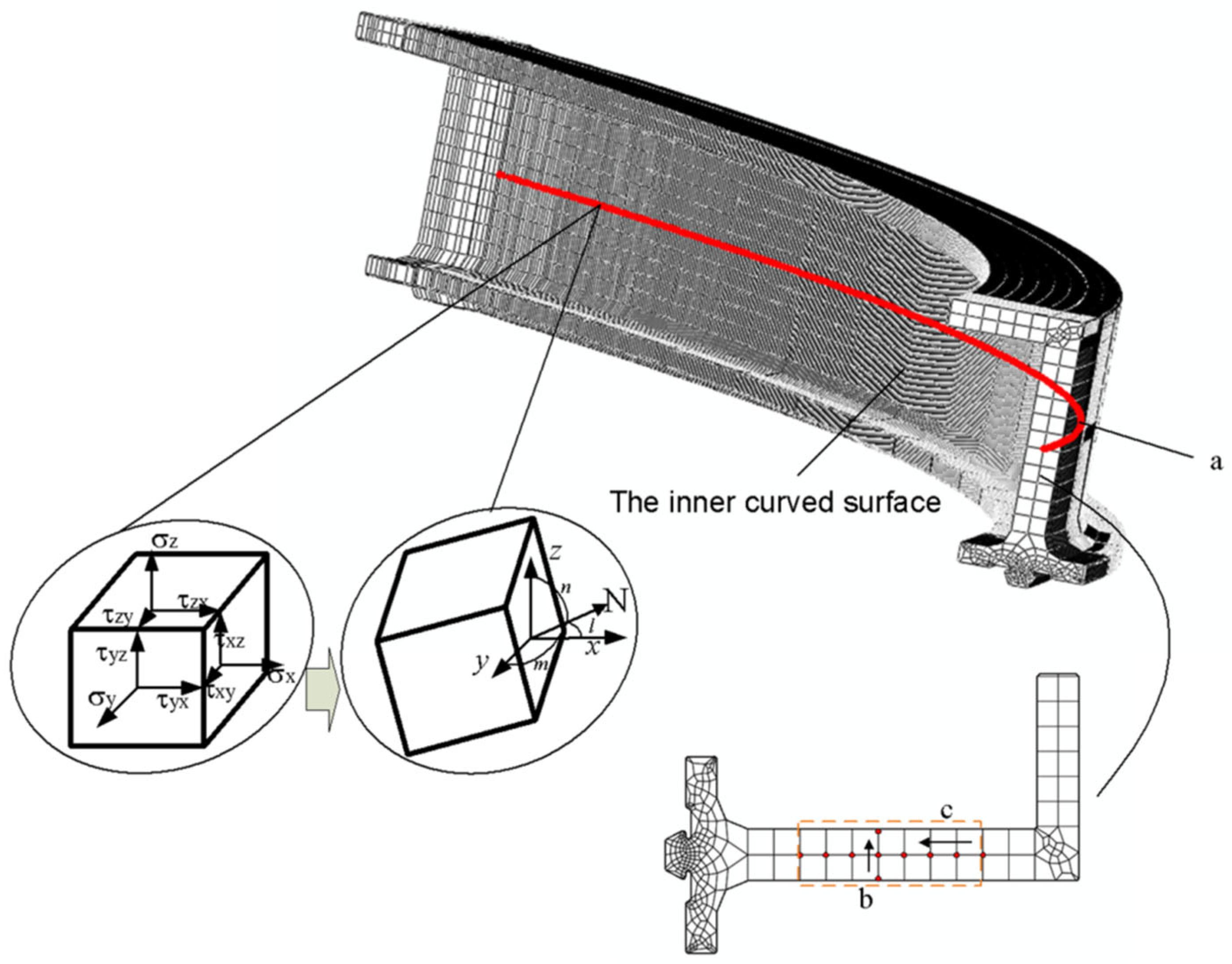
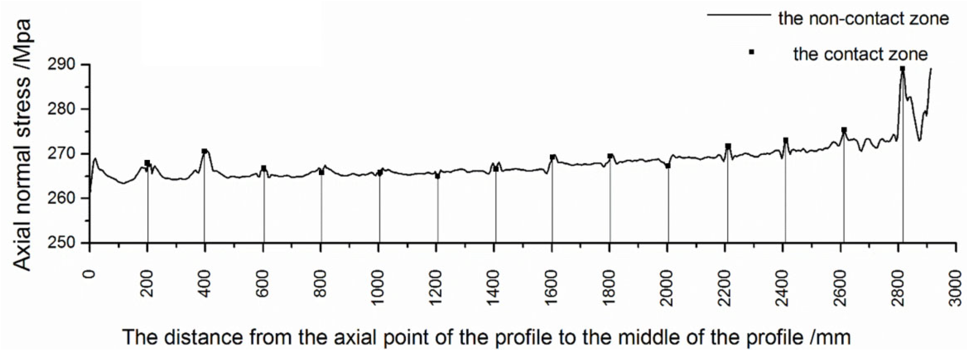
3.1. The Axial Normal Stress Analysis of Profile along Axial Direction

We selected the middle area of the web and took the same position points along the axial direction of the profile (path a), as shown in Figure 7. The ABAQUS software (Dassault, Providence, RI, USA) was used to output σx, σy, σz, τxy, τxz and τyz of the profile nodes. We wanted to explore the axial normal stress of the profile, so we made the normal of the cross-section N and obtained the direction cosine of the angle between the normal N and the three given coordinate axes, x, y and z; the cosine was l, m and n, as shown in Figure 7. The total stress on the cross-section was S, and its components along the three coordinate axes were Sx, Sy and Sz. According to the static equilibrium conditions, the following results were obtained:
S x = σ x l + τ y x m + τ z x n S y = τ x y l + σ y m + τ x y n S z = τ x z l + τ y z m + σ z n
where Sx is the component of the total stress S on the x-axis, Sy is the component of the total stress S on the y-axis, and Sz is the component of the total stress S on the z-axis.
The normal stress on the cross-section is σ:
σ = S x l + S y m + S z n
The shear stress on the cross-section is τ:
τ 2 = S 2 σ 2
Because the direction of normal stress was along the normal direction, the positive and negative value of stress had a physical meaning, and a positive value represented tension, while a negative value represented pressure. The shear stress was derived from Formula (7). Therefore, shear stress could not determine the direction but could only represent the size.
The axial normal stress of each point along path a was obtained as shown in Figure 8. Comparing the contact area and non-contact area between the profile and the multi-point molds, the axial and normal stresses in the contact area were much smaller. The value of axial normal stress in the non-contact zone was relatively stable, and there was a small increase on the side near the clamp. Because of the support force and friction force given by the die, the longitudinal fibers of the profile produced normal stress, which made the cross-section slightly deformed and unable to keep the plane, meaning the axial normal stress distribution in the contact zone and non-contact zone was different. The radial and circumferential normal stresses along the axial direction of the profile are shown in Figure 9. The axial normal stress near the clamp was large and fluctuating, which was caused by slight necking.

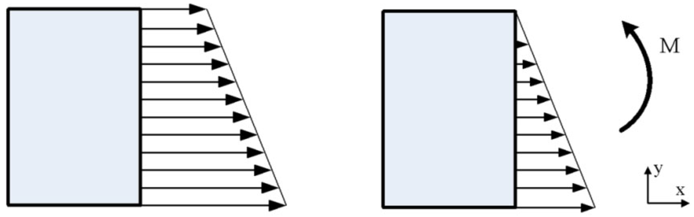
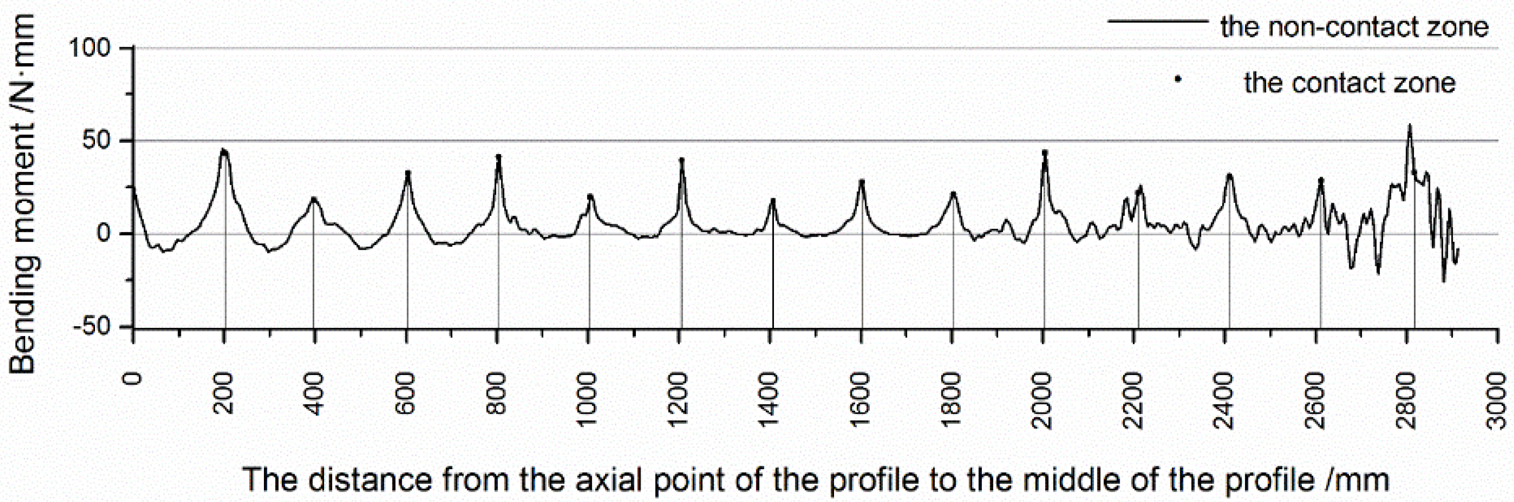
3.2. The Bending Moment Analysis of Profile along the Axial Direction

In the horizontal stretch bending of the FSB process, the axial normal stress of the cross-section makes the bending moment of the profile. We needed to obtain the axial normal stress on each cross-section to calculate the bending moment on the cross-section of the profile. We selected the middle area of the web as the research object, as shown in Figure 7.
Since the deformation of the profile is mostly plastic strain during the stretch bending process, there is no neutral layer on the profile section. As shown in Figure 7, the axial normal stress was output along path b at three different cross-sections of the profile. Their distances were the same. Through comparison, the axial normal stress difference was basically the same, as shown in Figure 10. Therefore, it could be proved that the normal stress had a linear relationship along the thickness of the profile web, and the distribution diagram of the axial normal stress of the section is shown in Figure 11. This satisfies the following formula [18]:
σ= k·y + σmin
where k is the normal stress parameter, y is the distance to the inner curved surface, and σmin is the axial normal stress at the inner curved surface.
We simulated the difference in normal stress between the outer and inner nodes of each section and divided them by the distance between the two nodes. We calculated the value of k using Formula (9) [18]:
k =△σ/△y
At three different cross-sections of the profile, the axial normal stress of the profile was output along path c. The output results are shown in Figure 10, and the results show that their size was basically unchanged. This proves that at the same cross-section in the middle of the web, the size of the axial normal stress was only related to the distance to the inner curved surface.
Since the profile was plastically deformed, and the stress on the cross-section was tensile stress, we needed to remove the normal stress that made the profile axially elongated, that is, the maximum value minus the minimum value to obtain the bending normal stress σbending, as shown in Figure 11.
σbending = k·y
We calculated the bending moment according to the bending moment in Formula (11):
M = ∫Abending dA
We combined Formula (10) to obtain the following formula:
M = k∫A y2dA
where ∫A y2dA = Iz is the moment of inertia of the cross-section towards the z-axis, and A is the area of the selected cross-section.
M = kIz
According to the calculation, the bending moment along the axial direction of the profile was obtained, as shown in Figure 12. The bending moment of the profile in the contact zone was obviously greater than that in the non-contact zone, and the bending moment gradually decreased to near zero from the contact zone to the non-contact zone. The bending deformation of the profile in the contact zone was obviously greater than that in the non-contact zone.

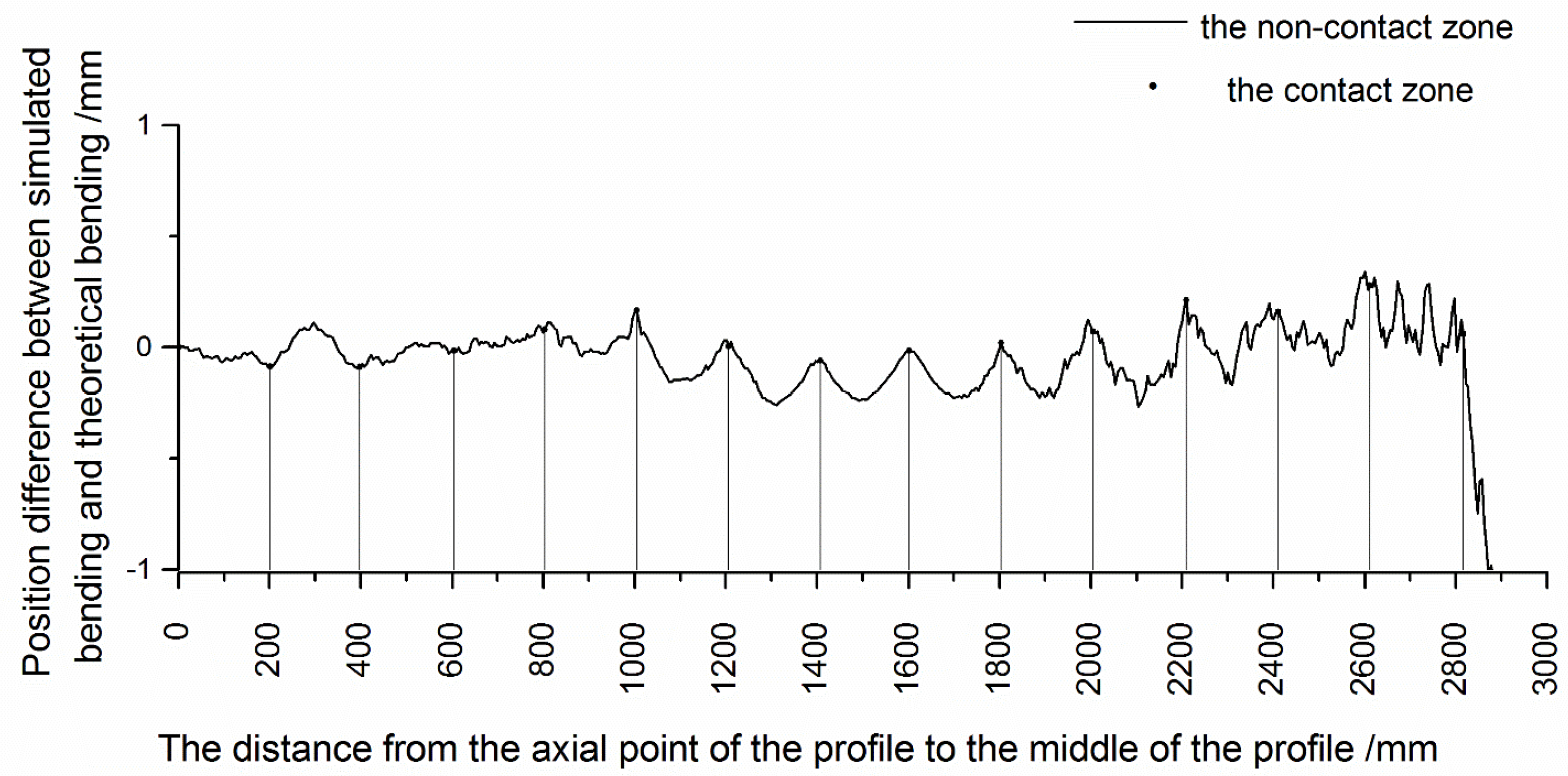
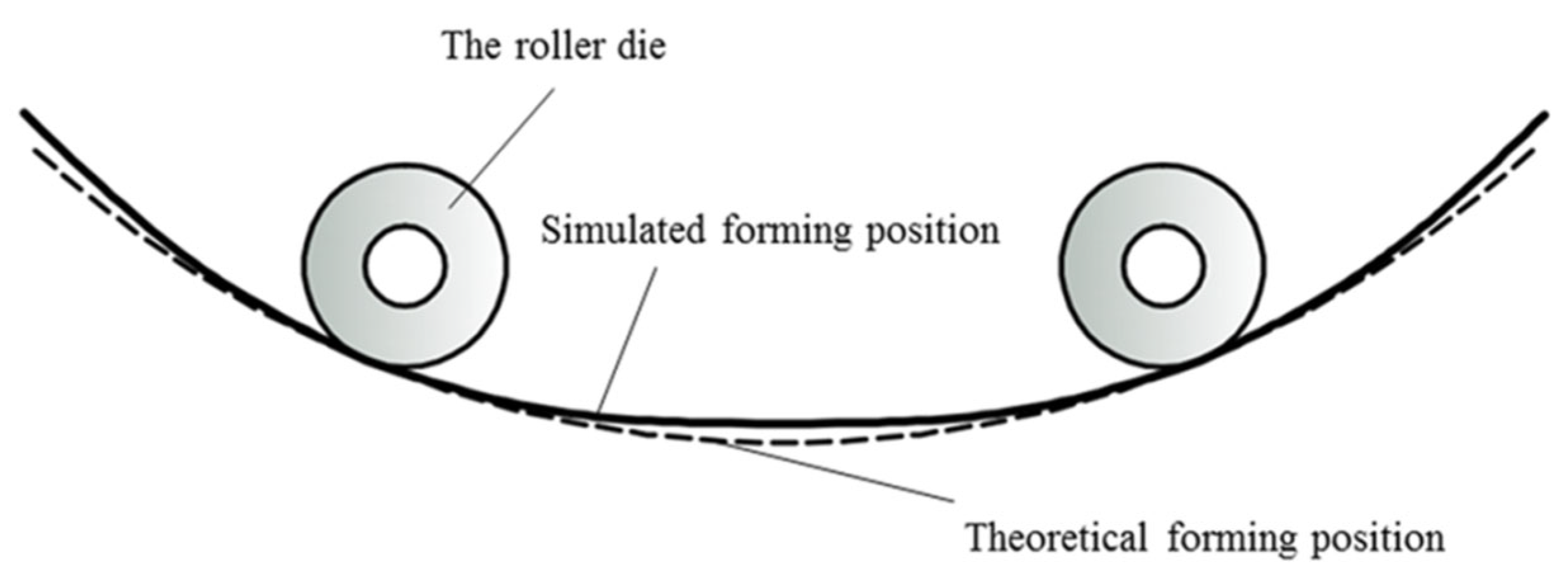
3.3. The Influence of Bending Moment Difference on Profile Deformation

Due to the difference in bending moment in the contact zone and non-contact zone, the simulated bending results were inevitably different from the theoretical bending results. The theoretical displacement change Δytheory along the bending direction of the node (path a) in the middle of the profile web was calculated using Formula (14) [19], and the simulated displacement Δysimulation along the bending direction was output by the finite element software. The difference between the two displacements is shown in Figure 13.
Δ y theory = R R 2 x simulation 2
where R is the bending radius and xsimulation is the coordinate of the node in the x-axis direction after simulation.
It can be seen from the figure above that the displacement of the profile in the contact zone and the non-contact zone was obviously different. In the non-contact zone, the profile deviated from the theoretical bending position, while in the contact zone, the offset of the profile decreased and was close to the theoretical bending position. The bending diagram of the contact zone and non-contact zone of the profile can be seen in Figure 14.

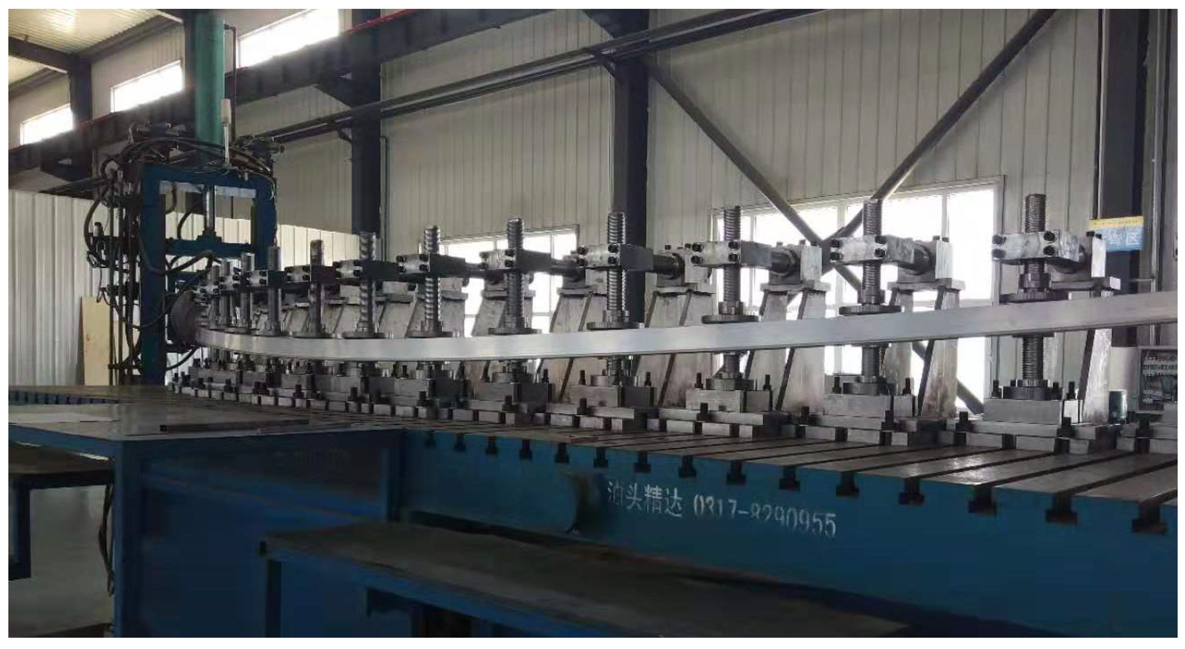
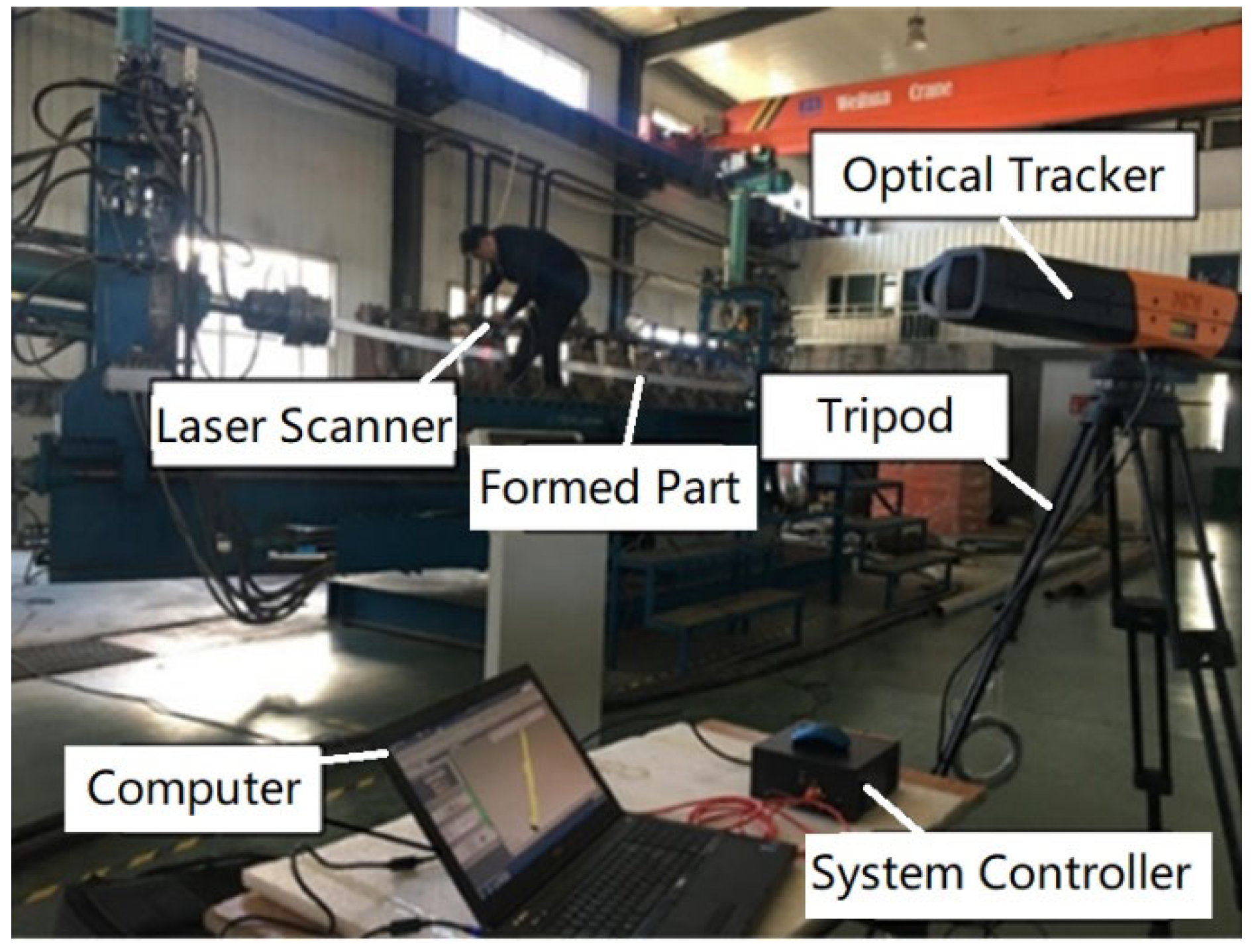
3.4. The FSB Experiment

In this experiment, a high-speed rail train head frame aluminum profile was taken as an example, and a 6000 mm, L-shaped aluminum profile was used in a horizontal stretch bending experiment on an FSB machine, as shown in Figure 15. It can be seen from the figure that there was no obvious deformation difference between the contact zone and non-contact zone of the profile, and the forming effect was wonderful. In order to further study whether the forming results of the contact zone and non-contact zone were similar to the simulation results, the 3D stretch bending part was scanned using the NDI large space measuring instrument, PRO CMM3500 optical tracker (Exactmetrology, Brookfield, WI, Canada) (Figure 16).
In the experiment, we selected the contact zone and the position of the non-contact zone between the two contact zones to measure the bending displacement of the middle of the web and compared these with those of the same part of the finite element model. Since the displacement of the two ends of the profile was extremely different, the simulated bending displacement and the experimental bending displacement were both subtracted from the theoretical bending displacement for comparison. The results are shown in Figure 17. From the abovementioned experimental results, it can be seen that the finite element model was consistent with the experimental results, and the validity of the numerical simulation results is confirmed.

4. Conclusions

(1)
The axial normal stress in the contact zone was smaller than that in the non-contact zone, and the axial normal stress in the contact zone fluctuated slightly, which was slightly higher than that in the non-contact zone. The value of axial normal stress in the non-contact zone was relatively stable, and there was a small increase on the side near the clamp. Because of the support force and friction force given by the die, the longitudinal fibers of the profile produced normal stress, which made the cross-section slightly deformed and unable to keep the plane, meaning the axial normal stress distribution in the contact zone and non-contact zone was different.
(2)
By simulating the axial normal stress on different cross-sections in the middle of three groups of webs, it was found that the value of axial normal stress on the same cross-section had a linear relationship with the distance to the inner curved surface, but their normal stress parameters were different on different cross-sections.
(3)
The bending moment of the profile in the contact zone was obviously greater than that in the non-contact zone, and the bending moment gradually decreased to near zero from the contact zone to the non-contact zone. The bending deformation of the profile in the contact zone was obviously greater than that in the non-contact zone.
(4)
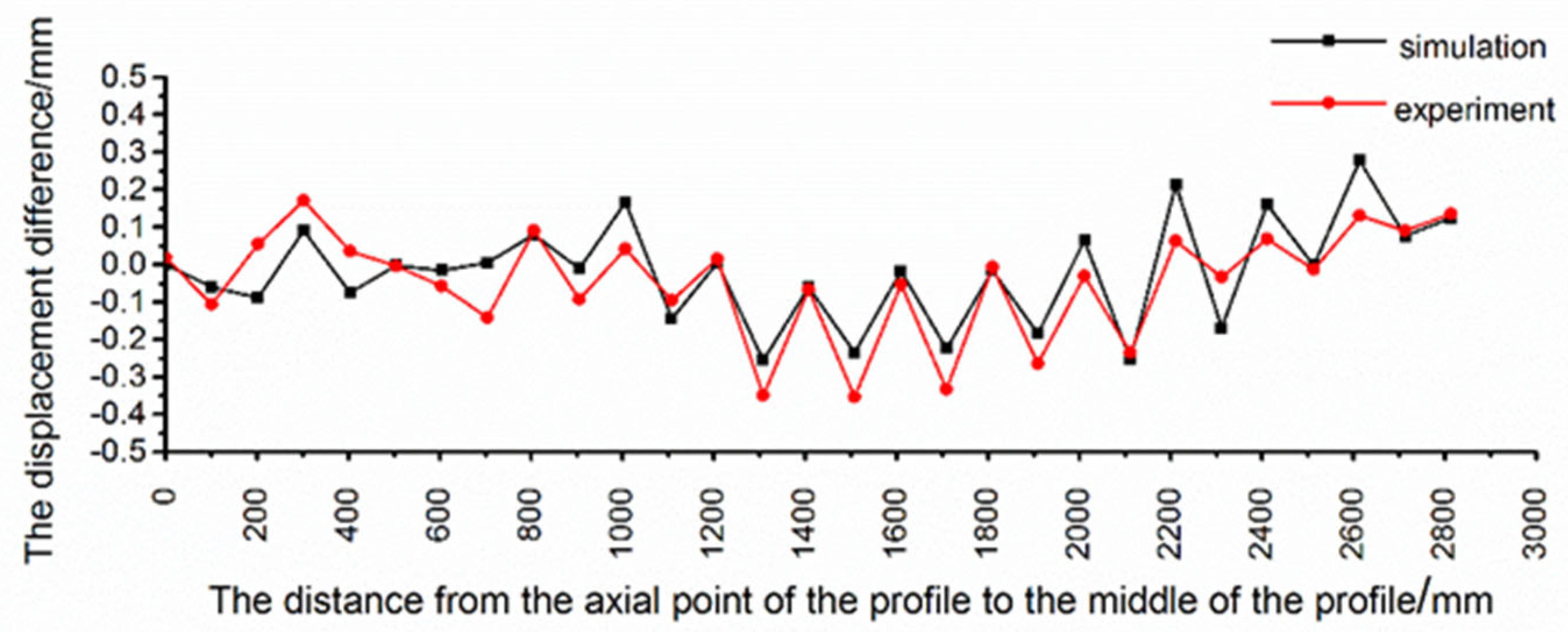
The displacement of the profile in the contact area and the non-contact area was obviously different. In the non-contact area, the profile deviated from the theoretical bending position, while in the contact area, the offset of the profile decreased and was close to the theoretical bending position.

Author Contributions

F.T. and J.L. conducted the numerical modeling and wrote the first draft of manuscript. J.L. provided the concept. F.T. and S.W. conducted the experiments. Q.H. edited the draft of manuscript. All authors have read and agreed to the published version of the manuscript.

Funding

This research was funded by Changchun University Scientific Research Cultivation Project, grant number ZKC201901, and the Project of Jilin Provincial Scientific and Technological Department, grant number 20210201121GX.

Institutional Review Board Statement

Not applicable.

Informed Consent Statement

Not applicable.

Data Availability Statement

The datasets used or analyzed in the current study are available from the corresponding author upon reasonable request.

Acknowledgments

The authors acknowledge all the authors who contributed to this article and the teachers who provided the test analysis.

Conflicts of Interest

The authors declare no conflict of interest.

References

  1. Corona, E. A simple analysis for bend-stretch forming of aluminum extrusion. Int. J. Mech. Sci. 2004, 46, 433–448. [Google Scholar] [CrossRef]
  2. Chatti, S.; Hermes, M.; Tekkaya, A.E.; Kleiner, M. The new TSS bending process: 3D bending of profiles with arbitrary cross-sections. CIRP Ann. Manuf. Technol. 2010, 59, 315–318. [Google Scholar] [CrossRef] [Green Version]
  3. Clausen, A.H.; Hopperstad, O.S.; Langseth, M. Stretch bending of aluminium extrusions for car bumpers. J. Mater. Process Technol. 2000, 102, 241–248. [Google Scholar] [CrossRef]
  4. Miller, J.E.; Kyriakides, S.; Bastard, A.H. On bend-stretch forming of aluminum extruded tubes—I: Experiments. Int. J. Mech. Sci. 2001, 43, 1283–1317. [Google Scholar] [CrossRef]
  5. Miller, J.E.; Kyriakides, S.; Corona, E. On bend-stretch forming of aluminum extruded tubes—II: Analysis. Int. J. Mech. Sci. 2001, 43, 1319–1338. [Google Scholar] [CrossRef]
  6. Li, M.Z.; Liu, Y.H.; Su, S.Z.; Li, G.Q. Multi-point forming: A flexible manufacturing method for a 3-d surface sheet. J. Mater. Process Technol. 1999, 87, 277–280. [Google Scholar] [CrossRef]
  7. Jicai, L.; Chengxiang, H.; Yi, L.; Kaifeng, Y.; Ce, L. Study on deformation difference between the contact zone and the non-contact zone of the flexible 3D stretch bending profile and roller dies based on pre-stretching amount. Int. J. Adv. Manuf. Technol. 2020, 108, 3579–3589. [Google Scholar]
  8. Yi, L.; Rui, L.; Ce, L.; Jicai, L.; Fei, T. Influence of the curvature of the multipoint die of flexible multipoint stretch bending on the quality of aluminum profile. Math. Probl. Eng. 2020, 5, 960–973. [Google Scholar]
  9. Liu, W.; Yang, Y.Y.; Li, M.Z. Numerical simulation of multi-point stretch forming and controlling on accuracy of formed workpiece. Int. J. Adv. Manuf. Technol. 2010, 50, 61–66. [Google Scholar] [CrossRef]
  10. Chen, J.; Fu, W.Z.; Li, M.Z. Local bending effect and its controlling methods in multi-point forming. Int. J. Adv. Manuf. Technol. 2017, 92, 4315–4322. [Google Scholar] [CrossRef]
  11. Yang, Z.; Cai, Z.Y.; Che, C.J.; Li, M.Z. Numerical simulation research on the loading trajectory in stretch forming process based on distributed displacement loading. Int. J. Adv. Manuf. Technol. 2016, 82, 1353–1362. [Google Scholar] [CrossRef]
  12. Zhou, Y.; Li, P.; Li, M.; Wang, L. Application and correction of L-shaped thin-wall aluminum in flexible-bending processing. Int. J. Adv. Manuf. Technol. 2017, 92, 981–988. [Google Scholar] [CrossRef]
  13. Jicai, L.; Yanfei, L.; Li, Y.I.; Ce, L. Study on the influence of bending angle of multipoint stretch-bending of profiles on section distortion of parts. Math. Probl. Eng. 2008, 2002, 1975805. [Google Scholar]
  14. Abosaf, M.; Essa, K.; Alghawail, A.; Tolipov, A.; Pham, D. Optimisation of multi-point forming process parameters. Int. J. Adv. Manuf. Technol. 2017, 92, 1–11. [Google Scholar] [CrossRef] [Green Version]
  15. Miyazaki, K.; Kanno, S.; Ishiwata, M.; Hasegawa, K.; Ahn, S.H.; Ando, K. Fracture behavior of carbon steel pipe with local wall thinning subjected to bending load. Nucl. Eng. Des. 1999, 191, 195–204. [Google Scholar] [CrossRef]
  16. Tang, N.C. Plastic-deformation analysis in tube bending. Int. J. Press. Ves. Pip. 2000, 77, 751–759. [Google Scholar] [CrossRef]
  17. Daniel, I.M.; Gdoutos, E.E.; Wang, K.A.; Abot, J.L. Failure Modes of Composite Sandwich Beams. Int. J. Damage Mech. 2002, 11, 309–334. [Google Scholar] [CrossRef]
  18. Jicai, L.; Chuandong, C.; Yi, L.; Ce, L. Effect of roller dies on springback law of profile for flexible 3D multi-point stretch bending. Int. J. Adv. Manuf. Technol. 2020, 108, 3765–3777. [Google Scholar]
  19. Hopperstad, O.S.; Leira, B.J.; Remseth, S. Reliability-based analysis of a stretch-bending process for aluminum extrusions. Comput. Struct. 1999, 71, 63–75. [Google Scholar] [CrossRef]
Figure 1. The schematic diagram of traditional stretch bending and FSB: (a) Overall die forming; (b) Multi-point die forming.
Metals 12 01168 g001
Figure 2. The FSB (Flexible 3D stretch bending) machine.
Metals 12 01168 g002
Figure 3. (a) The cross-section shape of profile, (b) stress–strain curve of aluminum profile.
Metals 12 01168 g003
Figure 4. The finite element model: (a) the roller die, (b) the clamp.
Metals 12 01168 g004
Figure 5. The assembly drawing.
Metals 12 01168 g005
Figure 6. The calculation diagram of special position of clamp track.
Metals 12 01168 g006
Figure 7. The calculation of axial normal stress, the profile measurement area and measurement paths.
Metals 12 01168 g007
Figure 8. The axial normal stress along path a.
Metals 12 01168 g008
Figure 9. The radial normal stress and circumferential normal stress; (a) the radial normal stress along path a; (b) the circumferential normal stress along path a.
Metals 12 01168 g009
Figure 10. The axial normal stress distribution of nodes along path b and path c.
Metals 12 01168 g010
Figure 11. The distribution of axial normal stress and bending stress at different distances from inner curved surface.
Metals 12 01168 g011
Figure 12. The distribution of bending moment in the forming profiles.
Metals 12 01168 g012
Figure 13. The displacement difference between simulated bending and theoretical bending of profile.
Metals 12 01168 g013
Figure 14. The schematic diagram of theoretical bending position and simulated bending position.
Metals 12 01168 g014
Figure 15. The FSB experiment equipment.
Metals 12 01168 g015
Figure 16. Optical tracking instrument.
Metals 12 01168 g016
Figure 17. The displacement difference between experiment and simulation.
Metals 12 01168 g017
Table 1. Material parameters.
E (MPa)νσb (MPa)Ρ (kg·m−3)
71,0000.332642.71
Table 2. Finite element model components, element types, number of elements and number of nodes.
Finite Element PartsUnit TypeNumber of UnitsNumber of Nodes
ProfileC3D8R69,60096,761
Multi-point moldR3D427332708
ClampR3D4138180
BracketR3D4168180
Publisher’s Note: MDPI stays neutral with regard to jurisdictional claims in published maps and institutional affiliations.

