Abstract
Although EK4 drawing steel is nowadays widely used to manufacture a great variety of parts, it exhibits a marked normal and planar anisotropy that can make it difficult to control the process during its forming. In order to achieve an accurate description of the elastoplastic material response in sheet forming operations, this work presents a detailed material and damage characterization of EK4 deep drawing steel through a two-step methodology involving both experiments and finite element simulations. Firstly, tensile tests on sheet samples cut along the rolling, diagonal and transverse directions were carried out. The corresponding measurements were used to calibrate the material parameters related to the following modeling approaches adopted in the present study: the Hollomon hardening law, the non-associated Hill-48 phenomenological constitutive model and the anisotropic Hosford-Coulomb ductile fracture criterion. Secondly, this characterization was assessed and validated in the numerical simulation of the technological Erichsen test in which the material is mainly subjected to a biaxial stress state. The obtained predictions show a good agreement when compared with the corresponding experimental measurements of the punch load–displacement curve and thickness radial profile at the final fracture stage of the sample.
1. Introduction
Given the importance of forming processes in modern manufacturing and due to the large number of incident variables in them, the demand for numerical analysis tools that allow optimization and implementation of new working conditions has grown in recent years, replacing methodologies that are usually more expensive as the standard trial and error approach [1]. Therefore, it is required that the solutions provided by numerical simulations be able to capture in the most reliable way possible all the mechanical effects induced on the material during forming operations. The application of models that extend the solution field by bringing improvements to process design and related operating conditions could consequently lead to more efficient use of the available resources.
Delimiting the field of study to deep drawing applications, the existing numerical simulations have usually tackled the problem assuming plane stress conditions. Thus, the shear stresses through the thickness of the blank are neglected. Moreover, the material may exhibit, due to previous cold and/or hot rolling operations, different in-plane mechanical responses that can be described through anisotropic constitutive models, whose material parameters are typically obtained from tensile tests of samples cut along characteristic directions defined in the plane of the sheet. This characterization is generally carried out taking as main axes rolling, diagonal and transversal directions (respectively denoted as 0°, 45° and 90°) and also, if available, the biaxial condition. Since this process allows manufacturing parts for a wide range of applications, the deep drawing failures observed in industrial environments are strongly associated with specific process operating conditions. As an attempt to recreate these failures at a laboratory scale, some technological tests such as the Erichsen and Swift devices are frequently performed to evaluate and experimentally validate numerical simulations aimed at describing all the phenomena involved in the process [2].
Among the great variety of constitutive models that have been developed during the last few decades to describe material behavior subjected to deep drawing, one of the most widely used is the classical anisotropic Hill-48 criterion [3], both in its general version and in its simplified form considering the hypothesis of planar isotropy (i.e., normal anisotropy). This criterion, which is available in many commercial sheet metal forming codes oriented to the simulation of industrial applications, incorporates material parameters that must be obtained from experimental tests specifically designed to this end. Its prediction capabilities assuming associated plastic flow have been assessed in many laboratory tests and successfully validated in industrial single and multi-step sheet forming problems, mainly for steels, e.g., the deep drawing EK4 [4,5], stainless AG-90 [6], ultra-low carbon titanium-stabilized interstitial free (ULC Ti-IF) [7], stainless SS304 [8] and dual-phase DP6112 [8] steels. The experimental validation of the numerical results provided by this model typically encompassed the punch force evolution together with the in-plane principal deformations and thickness distributions of the final deformed part [5,6]. This criterion has been also employed to study the effect of sheet anisotropy on the wear depth on the die shoulder [7]. An extension of the Hill-48 criterion using non-quadratic in the polynomial type has been also proposed to account for prediction discrepancies observed in the biaxial response of some alloys [9]. A new anisotropic yield criterion that circumvents this problem by presenting anisotropic behavior of characterized stress and strain states fully under the uniaxial tension and equibiaxial tension in the rolling, transverse and diagonal directions has been developed and applied to a hot dipped galvanized high-strength low-alloy steel (HSLA) [10]. A comparison of the performance of three recent advanced yield criteria [10,11,12] through the simulation of the hemispherical, cylindrical and square cup drawing processes has been carried out, where it was concluded that these models can predict better the sheet behavior observed in the experiments of two steels than the results obtained by using the von Mises and Hill-48 criteria [8]. Furthermore, advanced yield criteria have been also proposed and used to describe the particular response of aluminum [11,12,13,14] and zinc [15,16] alloys.
In practice, a relevant numerical simulation of the material response during deep drawing operations should include not only an adequate constitutive model to predict stress and plastic deformation fields but also a damage criterion to accurately establish the forming limits at necking or fracture stages. Various ductile fracture criteria based on an integral form of the equivalent plastic deformation have been proposed [6,17,18,19]. The results from these criteria generally reported acceptable predictions for the estimated forming limits. Moreover, more recent models based on the Lode angle and stress triaxiality have been adapted to describe anisotropic fracture [18,19]. It should be noted that these criteria also incorporate material parameters that must be derived from experiments in order to characterize the onset and end of failure.
The present work aims to study the elastoplastic response of the EK4 deep drawing steel. To this end, an exhaustive experimental and numerical characterization procedure using tensile tests in three particular directions is firstly performed. A non-associated Hill-48 plastic flow together with a decoupled Hosford-Coulomb ductile fracture criterion is utilized in the numerical simulations. Then, these previously characterized models are applied to the analysis of the technological Erichsen test where the obtained numerical results are extensively validated with the corresponding experimental measurements during the whole deformation range up to the fracture stage.
2. Materials and Methods
2.1. Material
The studied material corresponds to a deep drawing steel, typically applied for the manufacture of enameled parts named DC04EK4 (from here onwards, EK4 steel for short) according to the EN 10209 standards [20]. This steel is particularly used in the electrical household appliance industry. Due to the required mechanical properties for its manufacturing, metal sheets of 0.6 mm thickness are obtained after cold rolling which, as shown in Section 3, induces anisotropy on the resulting material.
2.2. Experimental Procedure
2.2.1. Tensile Tests
Tensile tests are performed in this work to characterize the mechanical behavior of the EK4 deep drawing steel. The geometry of the specimen is chosen following the ASTM standards [21]; see Figure 1. According to the standards, the sample considers a central area with a slightly lower width than the rest of the length, thus promoting necking and fracture in this section. This also ensures the correct positioning of the extensometer used for instantaneous length measurement. Due to steel anisotropy, these specimens are obtained from a cold rolled sheet in three particular directions, i.e., oriented to 0°, 45° and 90° with respect to the rolling direction.
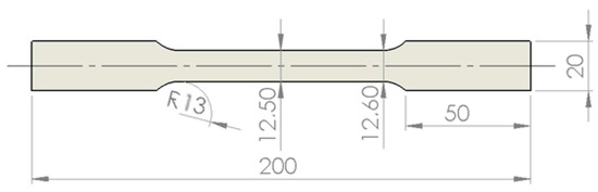
Figure 1.
EK4 steel sample (dimensions in mm).
The mechanical parameters are obtained through the engineering stress–strain curve , considering in this work four tests for each direction. The tests were performed setting the clamp advance as 2 mm/min, thus achieving quasi-static conditions. The curve is built with and , where is the instantaneous extensometer length with an initial value , is the load registered by the cell and is the initial transversal area at the central zone of the specimen. Moreover, the Young modulus , the yield stress (determined applying the offset method [21]), the maximum load , the ultimate tensile stress and the fracture strain are obtained as the mean value considering all the cases grouped by their sample direction.
The isotropic hardening is described by the Hollomon power law , where Ap and np are material parameters and εeq is the equivalent strain defined as , with being the instantaneous transversal area at the central zone of the specimen such that and are the instantaneous width and thickness, respectively. Usually, the characterization of the isotropic hardening law follows the least-squares minimization-based procedure described in [22] considering the material response in the homogeneous strain range in tensile samples cut along the rolling (0°) direction.
The Lankford coefficients associated with each sample direction, as indicated in the ASTM standards [23], are defined as for , where the initial width and thickness are, respectively, denoted by and . The working engineering strain range for measuring that guarantees uniaxial stress conditions should be considered. After obtaining each , it is possible to determine the mean Lankford coefficient of the metal sheet as and the earing tendency index as .
2.2.2. Erichsen Test
The technological Erichsen test is commonly carried out to estimate the forming capability of the selected material for deep drawing applications. In this test the material is mainly subjected to a biaxial stress state which constitutes one of the loading conditions typically encountered in industrial forming processes. Thus, through the action of a spherical punch head, plastic deformation is caused on the test specimen. As the material flow is rather limited, the tested sheet is finally fractured such that the measured displacement of the punch head that causes fracture is known as the Erichsen Index (EI). This final result can be directly associated with the material ductility, i.e., a higher EI should consequently be obtained from a material with a higher ductility and vice versa. Nevertheless, aside from the steel type, quality and chemical composition (e.g., carbon percentage), the EI also depends on the die diameter, the sample thickness and the applied lubricant in the test (e.g., greases, graphite or mineral oils).
As shown in Figure 2, the considered setup of the Erichsen test has a spherical punch head that induces plastic deformation on the circular sheet, a blank holder that fully limits the material flow from the external perimeter of the sheet to the inner zone and a die. Six samples were tested in this work. According to [24], in the present study the punch velocity was settled to 5 mm/min and the applied lubricant was the commercial grease Krytox (www.krytox.com, accessed on 14 March 2016). The friction conditions for this test were determined by the authors in previous works [4,5].
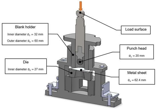
Figure 2.
Setup of the Erichsen test: schematic view and geometrical dimensions.
2.3. Constitutive Modelling
To successfully reproduce the material plastic anisotropy due the previous cold forming process, the Hill-48 phenomenological model in its non-associated form is selected in this work [3]. In this context, the yield criterion reads:
where is the Cauchy stress tensor, such that subscripts and , refer to the in-plane (with 1 and 2, respectively, associated in turn with the rolling (0°) and transversal (90°) directions) and out-of-plane (i.e., along the thickness) material orthotropic directions, is the yield stress obtained from the tensile sample cut along the rolling (0°) direction and is, as already mentioned, the Hollomon isotropic hardening function (with the hardening material parameters Ap and np derived from the material response in tensile samples cut along the rolling (0°) direction) expressed in this context in terms of the equivalent plastic strain whose rate is computed according to standard concepts of the plasticity theory. Moreover, the material parameters involved the square root term of Equation (1), i.e., the equivalent stress, are obtained as tensile stress ratios calculated based on the yield stresses for each direction (0°, 45°, 90°) as:
where are the yield stresses of each sample orientation while the biaxial yield stress can be estimated (when biaxial test measurements are not available) as [25]:
where are the Lankford coefficients associated, once again, to each sample orientation.
The present work dismisses the plane stress hypothesis commonly applied in deep drawing applications (note that this last assumption implies ). However, information regarding the material behavior in the plane of the sheet is, in general, not available. Thus, the incidence of the shear stresses related to the thickness direction, needed when using the 3D Hill criterion given by Equation (1), can be taken into account through the following expressions:
where coefficients L and M are, respectively, associated with the shear strengths in the 2–3 and 1–3 planes. A possible (not unique) approach is to consider as equivalent, from the point of view of resistance, the following two stress states: (1) pure shear in plane 2–3 and (2) pure shear in the same plane but rotated 45°. This assumption allows obtaining an estimation of coefficient L expressed by Equation (7). Coefficient M given by Equation (8) can be derived applying the same idea to the plane 1–3.
On the other hand, the plastic flow potential is also given by Equation (1) considering material parameters defined in terms of the Lankford coefficients as:
where and are calculated with Equations (7) and (8) but considering the expressions (9)–(11).
2.4. Damage Index
The uncoupled damage criterion selected in this work to predict crack initiation is based on the anisotropic Hosford-Coulomb model [19]. The model defines the fracture equivalent plastic strain as:
where is the experimentally measured equivalent plastic strain at the fracture stage for tensile samples cut along the rolling (0°) direction and is the Hosford-Coulomb equivalent stress written in terms of the principal stresses of as:
where is the Hosford-Coulomb exponent, is a friction parameter and is also expressed by Equation (14) but computed with the linear transformed stress tensor obtained via the following proposed expression for the transformation tensor M:
such that the parameters and are assumed to characterize the experimentally observed anisotropic character of the fracture strain. Finally, the damage index is defined as:
This criterion is assumed to predict the onset of fracture initiation occurring when the condition is accomplished. The parameters involved in this fracture criterion are obtained from the tensile tests at the three sample orientations described above. In the experiments, the fracture initiation stage is determined when the first crack is visually detected. In the numerical simulations, due to the non-homogeneous stress and strain fields attained in the vicinity of the cracking formation zone, the fracture initiation stage is defined as that when the average damage index in such zone achieves the value 1.
All the material parameters involved in the constitutive and damage models described above are obtained from tensile tests measurements according to the characterization procedure described in Section 3.1. On the other hand, the computational implementation and solution of both models is performed in the context of the finite element method via an in-house code [26] extensively validated in many engineering applications.
3. Results and Discussion
3.1. Tensile Tests
Figure 3 shows the experimental engineering stress–strain curves for tensile specimens of the EK4 steel oriented at 0°, 45° and 90° with respect to the rolling direction, while the average mechanical parameters obtained from these material responses are summarized in Table 1. The measurements in the elastic zone show similar yield stresses for the three sample orientations. The calculation methodology to obtain these elastic limits and Young moduli is based on the offset method [19]. For the following plastic zone, all sample directions exhibit a constant engineering stress experimental curve in the 15% to 30% engineering strain range, where uniform plastic strain develops under a uniaxial stress state. There are slight differences between the UTSs achieved for each orientation: the 45° specimen shows greater strength than those of the 0° and 90° directions. After the necking development, the engineering strain at the fracture stage is similar for the 0° and 90° samples, while a slightly lower value is observed for the 45° sample. Although the anisotropic character of the material is not apparent in the stress–strain curves shown in Figure 3, this effect can clearly be appreciated in the obtained values of the Lankford coefficients. These coefficients, assumed for simplicity as constants during the whole deformation process, are computed from the measurements of the instantaneous sample width and thickness according to the expression given in Section 2.2.1. These measurements are taken within the uniaxial stress range, i.e., 15–20% in this case. The resulting mean Lankford coefficient and earing tendency index are and , respectively (these values present a maximum difference of 17% compared to those published by the authors [4] using a similar material), values that clearly reflect the marked normal and planar anisotropy of this material. It should be mentioned that these particular plastic stress–strain responses cannot be properly described by neither the isotropic von Mises nor the associated anisotropic Hill yield criteria. This fact justifies the adoption of the non-associated plasticity model described in Section 2.3.
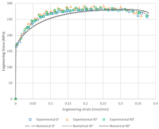
Figure 3.
Experimental and numerical engineering stress–strain curves for tensile specimens of the EK4 steel oriented at 0°, 45° and 90° with respect to the rolling direction.

Table 1.
Average mechanical parameters obtained from the tensile tests of the EK4 deep drawing steel.
The next step for the material characterization consists of the determination of the hardening parameters corresponding to the Hollomon law presented in Section 2.3. As already mentioned in Section 2.2.1, and due to the fact that the damage criterion described in Section 2.4 is assumed to be uncoupled from the plastic response, this calculation could be carried out analytically taking the strain range of homogeneous plastic behavior under a uniaxial stress state for the 0° sample (for this particular case, note that neither the equivalent stress nor the effective plastic deformation depend, by definition, on the Hill parameters due to the fulfillment the condition G + H = 1 for both the yield and plastic potential functions; see Equations (3) and (4) and Equations (10) and (11)). Nevertheless, in this work an alternative and more robust procedure based on the least-squares minimization between the experimental and numerical (obtained via finite element simulations of the tensile test for the 0° sample) results applied throughout the entire deformation range up to the fracture stage is adopted [6]. The hardening parameters thus obtained are included in Table 2, while the corresponding numerical stress–strain response for the sample oriented at 0° with respect to the rolling direction is depicted in Figure 3. Although the numerical prediction is relatively inaccurate at the beginning of the plastic zone, it properly describes the material hardening in the UTS-fracture range in which the stress triaxiality develops.
Table 2.
Parameters of the Hollomon isotropic hardening function and non-associated Hill-48 model of the EK4 drawing steel.
Figure 4 shows the experimental and numerical width and thickness ratios as a function of the engineering strain for tensile specimens of the EK4 steel oriented at 0°, 45° and 90° with respect to the rolling direction. These measurements, together with those of Figure 1, are the basis for the final step of the material characterization, i.e., the derivation of the parameters involved in the yield criterion and plastic flow potential of the non-associated Hill-48 model described above. To this end, the following methodology is proposed: an initial estimation of these parameters is firstly performed by means of the explicit expressions included in Section 2.3 and, secondly, a least-squares minimization-based procedure computing the error between the experimental and numerical results corresponding to the curves shown in Figure 3 and Figure 4 is applied. The resulting parameters are summarized in Table 2, while the corresponding predictions are plotted in Figure 1 and Figure 4, where it is seen that the overall material response is well captured by the numerical results, even beyond the onset of necking formation that for this material takes place at an engineering strain of around 32% for the three sample orientations.
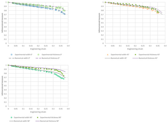
Figure 4.
Experimental and numerical width and thickness ratios as a function of the engineering strain for tensile specimens of the EK4 steel oriented at 0°, 45° and 90° with respect to the rolling direction.
The methodology to determine the parameters involved in the Hosford-Coulomb damage model presented in Section 2.4 consists of the following sequential steps: (a) adoption of exponent a as the same used in the Hill-48 yield criterion, (b) calculation, from the experimental measurements, of parameter b according to the expression of the equivalent strain given in Section 2.2.1 and (c) application of a least-squares minimization-based procedure computing the error between the experimental and numerical results corresponding to the fracture strain subjected to the condition (in average), considered separately for the sample directions 0°, 90° and 45°, which, respectively, allow to unequivocally obtain the parameters c, M22 and M12 (note that for this particular sample sequence, tensor M does not play any role for the 0° sample, only the parameter M22 is active for the 90° sample and, finally, the 45° sample allows determining the parameter M12). The average damage index is computed in a region of the finite element mesh that corresponds to a strip (whose width is assumed as the thickness of the sample) that contains the fracture bands observed in the experiments as shown in Figure 5, where the angle between bands is approximately 50° for all samples. Table 3 summarizes the parameters obtained with the proposed parameter calibration methodology, where it should be mentioned that the difference between the average experimental and numerical engineering strain at the fracture stage is less than 8% for all sample directions.
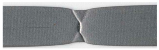
Figure 5.
Fracture stage of an EK4 steel tensile sample.
Table 3.
Parameters of the Hosford-Coulomb damage criterion of the EK4 drawing steel.
3.2. Erichsen Test
The numerical simulation of the Erichsen test is carried out to assess and experimentally validate the models presented in Section 2.3 and Section 2.4 and characterized via the tensile tests described in Section 3.1. The finite element discretization of the blank and tools (i.e., punch, die and blank holder) considered, due to symmetry, a fourth of the whole problem using 8640 8-noded elements for the sheet and 3536 rigid 4-noded elements for the tools. The mechanical interaction between the blank and tools is described through a contact model [26] considering a friction coefficient value of 0.168 for all interfaces [5].
Figure 6 shows the average experimental and numerical punch load–displacement curves up to the fracture stage of the samples. As can be seen, an overall good agreement between the measured and predicted results is achieved. The experimental maximum punch load occurs at the displacement that causes fracture, i.e., the Erichsen index (EI). Both values have very low dispersion, a fact that makes them reliable validation measures. In the numerical simulation, the maximum punch load is obtained at the instant in which a unit damage index is reached for the first time in any region of the sample along its thickness, see Figure 7. The computed values for the maximum punch load and EI are, respectively, 11.40 kN and 11.76 mm, which compare satisfactorily with the corresponding experimental mean values (for both variables, the experimental-numerical difference is less than 4%). These results confirm that the simplified damage characterization approach described in Section 3.1, where only tensile test measurements were used to identify the parameters of the Hosford-Coulomb damage model (fact that could certainly restrict its range of validity since only limited ranges of stress triaxiality and Lode angle were considered), is found to realistically predict failure under similar stress–strain conditions to those occurring in a standard sheet forming process. Moreover, as Equation (15) states, the damage evolution depends on both the stress and strain fields. Figure 8 depicts the numerical contours, at the fracture stage, of the three principal stresses. Although fracture occurs in a location for which the stress state is not strictly biaxial, the stress contours in that region do not differ too much from those corresponding to the dome (in which the biaxial plane-stress state is achieved). The main difference between both regions, which explains the location of the crack for this problem, is due to different levels of equivalent plastic strain developed in such locations.
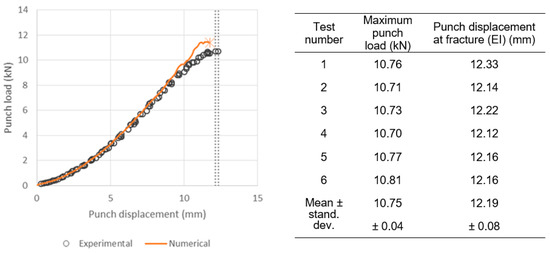
Figure 6.
Erichsen test of the EK4 steel: average experimental and numerical punch load–displacement curves where the dotted lines indicate the fracture range measured in the tested specimens.
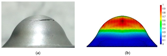
Figure 7.
Erichsen test of the EK4 steel: (a) Fracture stage of the sample showing a crack near its cup and (b) numerical damage index contours exhibiting a maximum value in the same cracked zone of the sample.
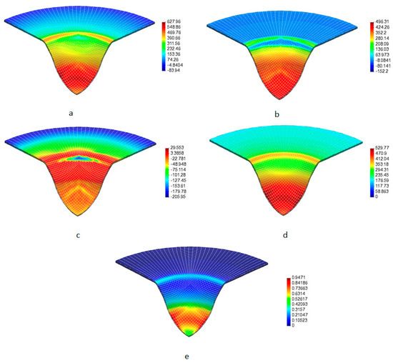
Figure 8.
Erichsen test of the EK4 steel: numerical contours at the fracture stage. (a–c) principal stresses (in-plane and and out-of-plane ), (d) equivalent stress and (e) effective plastic deformation.
The experimental and numerical dimensionless thickness (i.e., final/initial thickness ratio) radial profiles at the final fracture stage of the sample are plotted in Figure 9. The computed results are found to adequately capture the thickness profile along the whole radius of the sample. As expected, fracture occurs at the location of maximum thickness reduction, i.e., at a radial distance of 6 mm from the center of the sample. The areas in contact and close to the punch head are highly deformed. The numerical approximation accurately describes this behavior, even in these areas of high plastic deformation. The scatter in the thickness measurements obtained in this region is due to the dispersion of the crack location in the tested samples. Finally, the numerical results are also consistent in the outer regions of the specimen, which do not suffer major deformation due to the fact that there is no significant material flow in them.
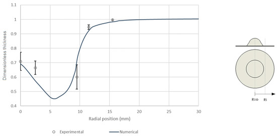
Figure 9.
Erichsen test of the EK4 steel: experimental and numerical dimensionless thickness radial profiles at the final fracture stage of the sample.
4. Conclusions
In the present paper, an elastoplastic constitutive formulation for sheet metal forming based on the non-associated Hill-48 function coupled with the anisotropic Hosford-Coulomb ductile fracture criterion are analyzed. Mechanical hardening was taken into account using the classical Hollomon-type law. The yield stress and R-values obtained in uniaxial tensile tests for the EK4 deep drawing steel sheet samples with different alignment with respect to the rolling direction were used to calibrate the developed formulation. In particular, for tensile specimens oriented at 0°, 45° and 90°, with respect to the rolling direction, the analyzed non-associated model show that results are acceptable predictions of both width and thickness ratios as a function of axial deformation. The model was also validated in the numerical simulation of the technological Erichsen test, where the obtained numerical results show good agreement when compared with the corresponding experimental measurements of the punch load–displacement curve and thickness radial profile at the final fracture stage of the sample. Finally, the presented results indicate that the non-associated Hill-48 model in conjunction with the Hosford-Coulomb anisotropic ductile fracture criterion is a suitable approach to describe the response of EK4 deep drawing steel.
Future work will be focus on the assessment of alternative damage and failure models, such as the so-called “Generalized Incremental Stress State dependent damage MOdel” (GISSMO) or coupled plasticity-damage models (e.g., Lemaitre or Gurson approaches), in more complex forming paths such as those present in multistep deep drawing processes.
Author Contributions
Conceptualization and design of a project, C.G.-H. and D.J.C.; analysis of results C.B., C.G.-H., D.J.C. and J.W.S.; simulations, C.B.; design, construction and experiments, C.B.; writing—original draft preparation, C.B. and D.J.C.; writing—review and editing, C.B., C.G.-H., D.J.C. and J.W.S.; supervision, C.G.-H. and D.J.C.; funding acquisition, D.J.C. All authors have read and agreed to the published version of the manuscript.
Funding
This work was financially supported by the Chilean Agency of Research and Development (ANID) through Fondecyt Project 1180591.
Institutional Review Board Statement
Not applicable.
Informed Consent Statement
Not applicable.
Data Availability Statement
All data supporting published results can be found in this paper.
Acknowledgments
The support provided by the Chilean Council for Research and Development ANID through FONDECYT Project No. 1180591 is gratefully acknowledged.
Conflicts of Interest
The authors declare no conflict of interest.
References
- Ponthot, J.-P.; Feulvarch, E.; Drapier, S.; Bergheau, J.-M. Editorial for thematic issues: Computational methods in manufacturing. Int. J. Mater. Form. 2017, 10, 1–2. [Google Scholar] [CrossRef][Green Version]
- Banabic, D.; Bunge, H.-J.; Pöhlandt, K.; Tekkaya, A.E. Formability of Metallic Materials; Springer: Berlin/Heidelberg, Germany; New York, NY, USA, 2000. [Google Scholar] [CrossRef]
- Hill, R. A Theory of the Yielding and Plastic Flow of Anisotropic Metals. Proc. R. Soc. Lond. Ser. A Math. Phys. Sci. 1948, 193, 281–297. [Google Scholar] [CrossRef]
- García, C.; Celentano, D.; Flores, F.; Ponthot, J.-P. Numerical modelling and experimental validation of steel deep drawing processes: Part I. Material characterization. J. Mater. Process. Technol. 2006, 172, 451–460. [Google Scholar] [CrossRef]
- García, C.; Celentano, D.; Flores, F.; Ponthot, J.-P.; Oliva, O. Numerical Modelling and Experimental Validation of Steel Deep Drawing Processes. Part II: Aplications. J. Mater. Process. Technol. 2006, 172, 461–471. [Google Scholar] [CrossRef]
- Pacheco, M.; Celentano, D.; Garcia-Herrera, C.; Méndez, J.; Flores, F. Numerical simulation and experimental validation of a multi-step deep drawing process. Int. J. Mater. Form. 2015, 10, 15–27. [Google Scholar] [CrossRef]
- Salehinia, I.; Shahani, A. Effect of sheet anisotropy on the wear in deep-drawing process of a cylindrical cup. Int. J. Mech. Sci. 2009, 51, 856–868. [Google Scholar] [CrossRef]
- Cogun, F.; Darendeliler, H. Comparison of different yield criteria in various deep drawn cups. Int. J. Mater. Form. 2017, 10, 85–98. [Google Scholar] [CrossRef]
- Hosford, W.F. On yield loci of anisotropic cubic metals. In Proceedings of the 7th North American Metalworking Conference, Dearborn, MI, USA, 15–18 April 1979; SME: Dearborn, MI, USA; pp. 191–197. [Google Scholar]
- Hu, W. Characterized behaviors and corresponding yield criterion of anisotropic sheet metals. Mater. Sci. Eng. A 2003, 345, 139–144. [Google Scholar] [CrossRef]
- Aretz, H. A non-quadratic plane stress yield function for orthotropic sheet metals. J. Mater. Process. Technol. 2005, 168, 1–9. [Google Scholar] [CrossRef]
- Banabic, D.S.; Comsa, D. Plane-stress yield criterion for highly-anisotropic sheet metals. In Proceedings of the 7th International Conference and Workshop on Numerical Simulation of 3D Sheet Metal Forming Processes, Numisheet, Interlaken, Switzerland, 1–5 September 2008; pp. 43–48. [Google Scholar]
- Neto, D.M.; Oliveira, M.; Dick, R.E.; Barros, P.D.; Alves, J.L.C.M.; Menezes, L.F. Numerical and experimental analysis of wrinkling during the cup drawing of an AA5042 aluminium alloy. Int. J. Mater. Form. 2015, 10, 125–138. [Google Scholar] [CrossRef]
- Cazacu, O.; Barlat, F. Generalization of Drucker’s Yield Criterion to Orthotropy. Math. Mech. Solids 2001, 6, 613–630. [Google Scholar] [CrossRef]
- Alister, F.; Celentano, D.; Signorelli, J.; Bouchard, P.-O.; Pino, D.; Cruchaga, M. Pino Characterization of the Elastoplastic Response of Low Zn-Cu-Ti Alloy Sheets Using the CPB-06 Criterion. Materials 2019, 12, 3072. [Google Scholar] [CrossRef] [PubMed]
- Alister, F.; Celentano, D.; Nicoletti, E.; Signorelli, J.; Bouchard, P.-O.; Pino, D.; Pradille, C.; Cruchaga, M. Elastoplastic Characterization of Zn-Cu-Ti Alloy Sheets: Experiments, Modeling, and Simulation. J. Mater. Eng. Perform. 2022, 31, 1512–1529. [Google Scholar] [CrossRef]
- Han, H.N.; Kim, K.-H. A ductile fracture criterion in sheet metal forming process. J. Mater. Process. Technol. 2003, 142, 231–238. [Google Scholar] [CrossRef]
- Beese, A.; Luo, M.; Li, Y.; Bai, Y.; Wierzbicki, T. Partially coupled anisotropic fracture model for aluminum sheets. Eng. Fract. Mech. 2010, 77, 1128–1152. [Google Scholar] [CrossRef]
- Mohr, D.; Gu, G. Anisotropic Hosford–Coulomb fracture initiation model: Theory and application. Eng. Fract. Mech. 2015, 147, 480–497. [Google Scholar] [CrossRef]
- DIN EN 10209; Cold Rolled Low Carbon Steel Flat Products for Vitreous Enamelling-Technical Delivery Conditions. European Committee For Standardization: Pilsen, Czech Republic, 2013.
- ASTM International. Standard Test Methods for Tension Testing of Metallic Materials; E8/E8m15-a.[s.l.]; ASTM International: West Conshehoken, PA, USA, 2015. [Google Scholar]
- ASTM International. Standard Test Method for Tensile Strain-Hardening Exponents (n-Values) of Metallic Sheet Materials; E646-07e1.[s.l.]; ASTM International: West Conshehoken, PA, USA, 2014. [Google Scholar]
- ASTM International. Standard Test Method for Plastic Strain Ratio R for Sheet Metal; E517-00. [s.l.] ; ASTM International: West Conshehoken, PA, USA, 2010. [Google Scholar]
- ASTM International. Standard Test Method for Ball Punch Deformation of Metallic Sheet Material; E643-09. [s.l.]; ASTM International: West Conshehoken, PA, USA, 2009. [Google Scholar]
- Yan, Y.; Wang, H.; Li, Q. The inverse parameter identification of Hill 48 yield criterion and its verification in press bending and roll forming process simulations. J. Manuf. Process. 2015, 20, 46–53. [Google Scholar] [CrossRef]
- Celentano, D.J.; Guelorget, B.; François, M.; A Cruchaga, M.; Slimane, A. Numerical simulation and experimental validation of the microindentation test applied to bulk elastoplastic materials. Model. Simul. Mater. Sci. Eng. 2012, 20, 045007. [Google Scholar] [CrossRef]
Publisher’s Note: MDPI stays neutral with regard to jurisdictional claims in published maps and institutional affiliations. |
© 2022 by the authors. Licensee MDPI, Basel, Switzerland. This article is an open access article distributed under the terms and conditions of the Creative Commons Attribution (CC BY) license (https://creativecommons.org/licenses/by/4.0/).