Article

Plastic Deformation Mechanism and Slip Transmission Behavior of Commercially Pure Ti during In Situ Tensile Deformation

1
Xi’an Rare Metal Materials Institute Co., Ltd., Xi’an 710049, China
2
School of Energy Engineering, Huanghuai University, Zhumadian 463000, China
3
State Key Laboratory of Advanced Processing and Recycling of Non-Ferrous Metals, Department of Materials Science and Engineering, Lanzhou University of Technology, Lanzhou 730050, China
4
School of Materials Science and Engineering, Shaanxi University of Technology, Hanzhong 723001, China
5
School of Materials Science and Engineering, Zhengzhou University, Zhengzhou 450001, China
*
Authors to whom correspondence should be addressed.
Metals 2022, 12(5), 721; https://doi.org/10.3390/met12050721
Submission received: 24 March 2022 / Revised: 14 April 2022 / Accepted: 19 April 2022 / Published: 24 April 2022

Abstract

:
The plastic deformation modes of commercially pure titanium (CP-Ti) were studied using an in situ tensile test monitored by electron-backscatter-diffraction (EBSD) assisted slip trace analysis. The plastic strain was primarily accommodated by prismatic slip, followed by deformation twins and pyramidal slip. The slip transmission between two adjacent grains was predicted using the geometric compatibility factor m , which influenced not only the degree of stress concentration but also the activity of dislocation slip systems. Stress concentration mainly occurred at GBs with an m less than 0.5 and could be released by the activities of pyramidal slip or deformation twins with high critical shear stress (CRSS).

1. Introduction

Commercially pure titanium (CP-Ti) has been widely used in the biomedical field because of its excellent corrosion resistance, high fracture toughness, and good biocompatibility [1,2]. CP-Ti has a hexagonal close-packed (hcp) structure at room temperature and exhibits complex plastic deformation mechanisms due to the low symmetry of the hcp structure. Four slip systems, including prismatic slip, basal slip, pyramidal a , and c + a slips, and six deformation twins (DTs), including the { 10 1 ¯ 2 } 1 ¯ 011 , { 11 2 ¯ 1 } 11 2 ¯ 6 , and { 11 2 ¯ 3 } 11 2 ¯ 2 tension twins and the { 10 1 ¯ 1 } 10 1 ¯ 2 , { 11 2 ¯ 2 } 11 2 ¯ 3 , and { 11 2 ¯ 4 } 22 4 ¯ 3 compression twins, have been reported [3,4,5]. For a particular grain, the ease of these deformation modes is generally determined by the critical shear stress (CRSS) and the Schmid factor (SF).
Recently, the phenomenon of slip transmission has been observed in some specific circumstances. It has been proposed that the slip transmission between grain boundaries (GBs) is an important mode of coordinated deformation and plays an important role in the damage of polycrystalline [6,7,8,9]. Slip transmission behavior can be predicted using the geometric compatibility factor m . The m is given by m = c o s φ c o s γ where φ is the angle between the normal direction of the slip planes on both sides of the GBs, and γ is the angle between the slip directions of two adjacent grains. In general, slip is hindered by the GBs when m is less than 0.7; however, it can pass the GBs with little obstacle when m is larger than 0.7 [10,11,12,13,14].
GB- and twin-boundary-(TB) cracking are the major crack initiation mechanisms of Ti alloys due to the blocking of GBs and TBs on dislocations [15,16,17]. The crack initiation of a Ti alloy is delayed when the stress or strain concentration at GBs and TBs is alleviated through slip transmission. A better understanding of slip transmission is of great significance for improving the mechanical properties of Ti and its alloys.
In this work, CP-Ti (TA2) is selected and deformed by in situ tensile tests. The activities of slip systems and DTs are identified based on electron backscatter diffraction (EBSD) and slip trace analysis [18,19,20,21], and the emphasis is placed on slip transmission behavior and its influence on the activity of deformation modes.

2. Experimental

TA2 bars with a diameter of 10 mm were supplied by the Northwest Institute For Non-ferrous Metal Research, and their chemical composition is shown in Table 1. The as-received bars were first annealed at 450 °C for 1 h with furnace cooling to achieve a low residual stress state, and then dog-bone-shaped in situ tensile samples with a gauge section of 4 mm length, 3.5 mm width, and 0.5 mm thickness were cut from the annealed bars using discharged machining. The samples were mechanically ground to 1500 grit and then electropolished to produce a mirror-like surface using 10% HClO4 and 90% C2H5OH.
In situ tensile tests were conducted by scanning electron microscopy (SEM, Gatan mtest 2000, Gatan, Pleasanton, CA, USA) at a strain rate of 2.1 × 10⁻⁴ s−1 (a loading velocity of 8.3 × 10⁻⁴ mm·s−1). For the observation of microstructure, the tensile tests were interrupted by controlling the strain at ~2.9% (with displacement at 0.117 mm) and ~22.5%. The in situ tensile tests were stopped after the strain of ~22.5% for observation using a confocal laser scanning microscope (CLSM, ZEISS, Oberkochen, Germany). The EBSD measurements were conducted at an accelerating voltage of 20 kV with different step sizes depending on the desire (0.2~1 µm). The grain size, crystal orientation, and SF before and after in situ tensile testing were analyzed using Channel 5 software 5.11, Oxford Instruments, Abingdon, UK. The slip activities of the deformed grains were identified based on EBSD (Oxford Nordlys Max, Oxford Instruments, Abingdon, UK) and slip trace analysis [22,23]. The geometric compatibility factor m of the grains after in situ tension was calculated using Mtex-5.7.0 and Matlab software 2018a, MathWorks, Natick, MA, USA, and the influence of slip transmission behavior on the activity of deformation systems was further analyzed.

3. Results and Discussion

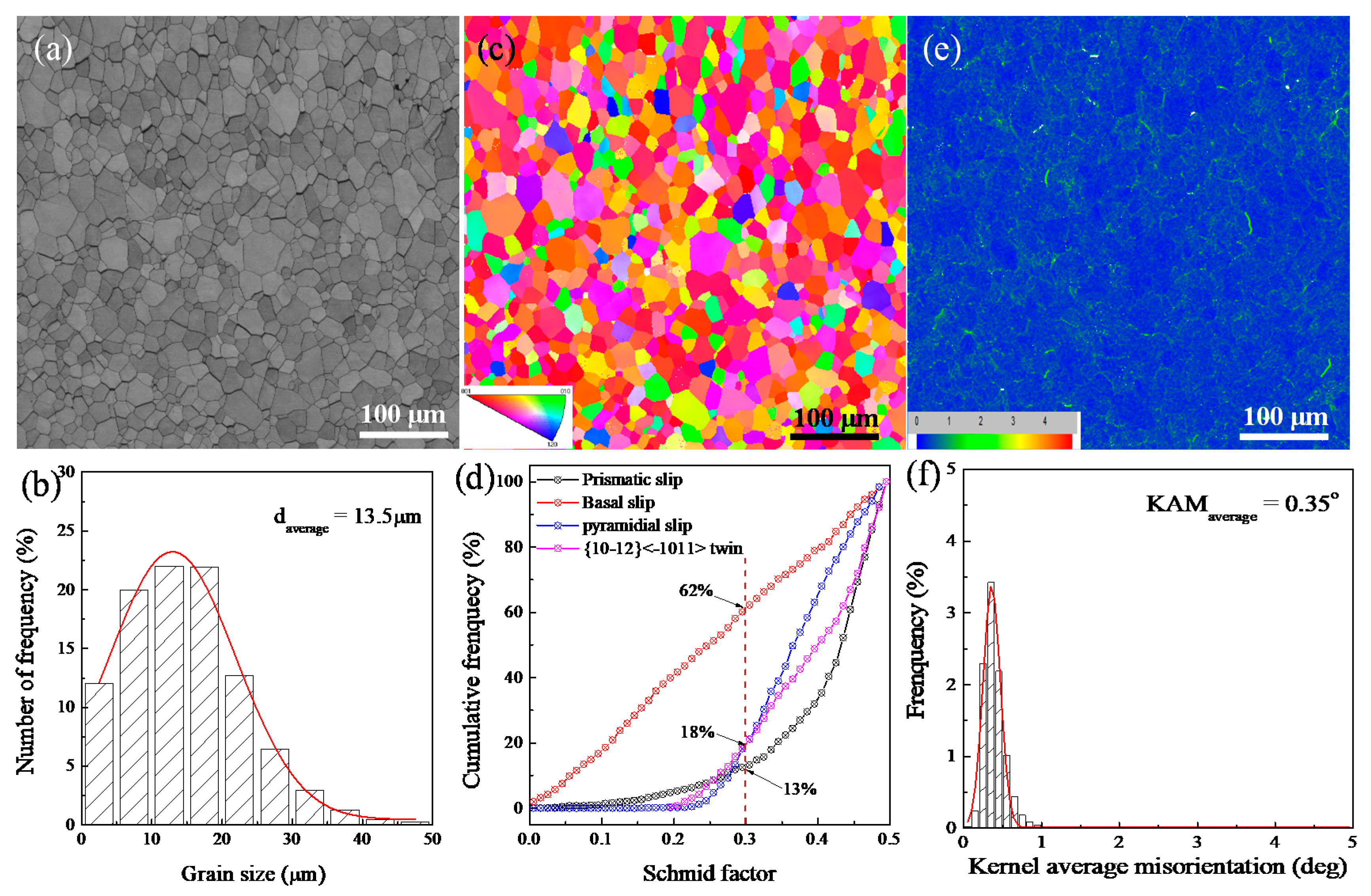
3.1. Initial Microstructure

The initial microstructural characteristics, including the band contrast (BC) image, inverse pole figure (IPF), and a kernel average misorientation (KAM) map, as well as the grain size distribution, the cumulative frequency of SF for the different deformation modes, and the KAM distribution, are shown in Figure 1a–f, respectively.
It is clear that the initial microstructure was a typical equiaxed α grain with an average grain size of 13.5 μm. The IPF suggests the c-axials of most grains were parallel with the normal direction, as shown in Figure 1c. It can be found from Figure 1d that the frequencies of SFs greater than 0.3 for prismatic slips, pyramidal slips, { 10 1 ¯ 2 } 1 ¯ 011 twins, and basal slips were 87%, 82%, 82%, and 38%, respectively. Because the CRSS of the prismatic, basal, pyramidal slips, and { 10 1 ¯ 2 } 1 ¯ 011 twins were measured to be 96 ± 18 MPa, 127 ± 33 MPa, 240 MPa, and 494 MPa, respectively [24,25], it was inferred that prismatic slips were primarily activated during in situ tensile deformation. Figure 1e,f demonstrate that the density of the geometry necessary dislocation (GND) in the initial stage was relatively low.

3.2. Dislocation Slip during In Situ Tensile Testing

The displacement-load curve during in situ tensile testing is shown in Figure 2a. The SEM micrograph and the corresponding IPF at the tensile displacement of 0.117 mm (at a strain of ~2.9%) along the direction parallel to the black double-headed arrow are shown in Figure 2b,c. Obviously, a number of parallel slip bands and deformation twins (DTs) were observed in some grains, which was marked by the number of the IPF. The activated deformation modes in the marked grains were distinguished by trace analysis, and the activated deformation modes, as well as their SFs, were marked in the SEM image. The red, yellow, and blue lines represent the plane traces of prismatic slip, pyramidal slip, and DTs, respectively.
In Figure 2d,e, the KAM map illustrates that, after a tensile strain of ~2.9%, the plastic strain mainly accumulated at some GBs, and some GBs could not be resolved due to the large amount of dislocation pile-up, as indicated by the white arrows in Figure 2f. Meanwhile, the average KAM increased from the initial microstructure of 0.35° to 0.49°. The density of the GND ( ρ G N D ) was estimated using the following formula [26,27,28]:
ρ G N D 2 KAM a v g b · R
where KAM a v g is the average value of KAM, b is the magnitude of the Burgers vector of dislocations (a = 0.295 nm and c = 0.468 nm for HCP Ti), and R is the step size (0.5 μm). We concluded that the density of GND increased obviously after tensile deformation. Further observations found that not all GBs had strong hindrance to dislocation and accumulated a large amount of plastic strain. Combined with the geometric compatibility factor ( m ) map in Figure 2f, it was found that plastic strain accumulation mainly occurred at GBs with an m less than 0.7. Because the cracks were preferentially initiated at GBs that accumulated serious plastic strain during further deformation, slip transmission behavior had an influence on the accumulation degree of plastic strain at GBs. In other words, the accumulation degree of the plastic strain at GBs decreased with the increase in m .

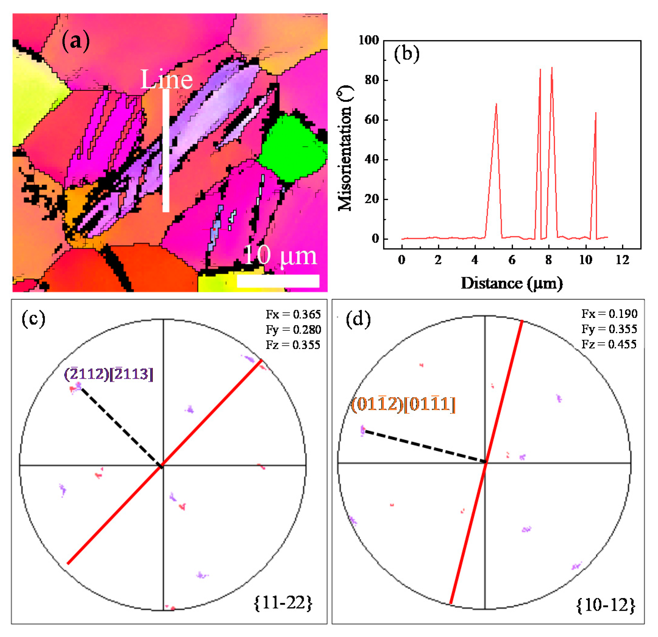
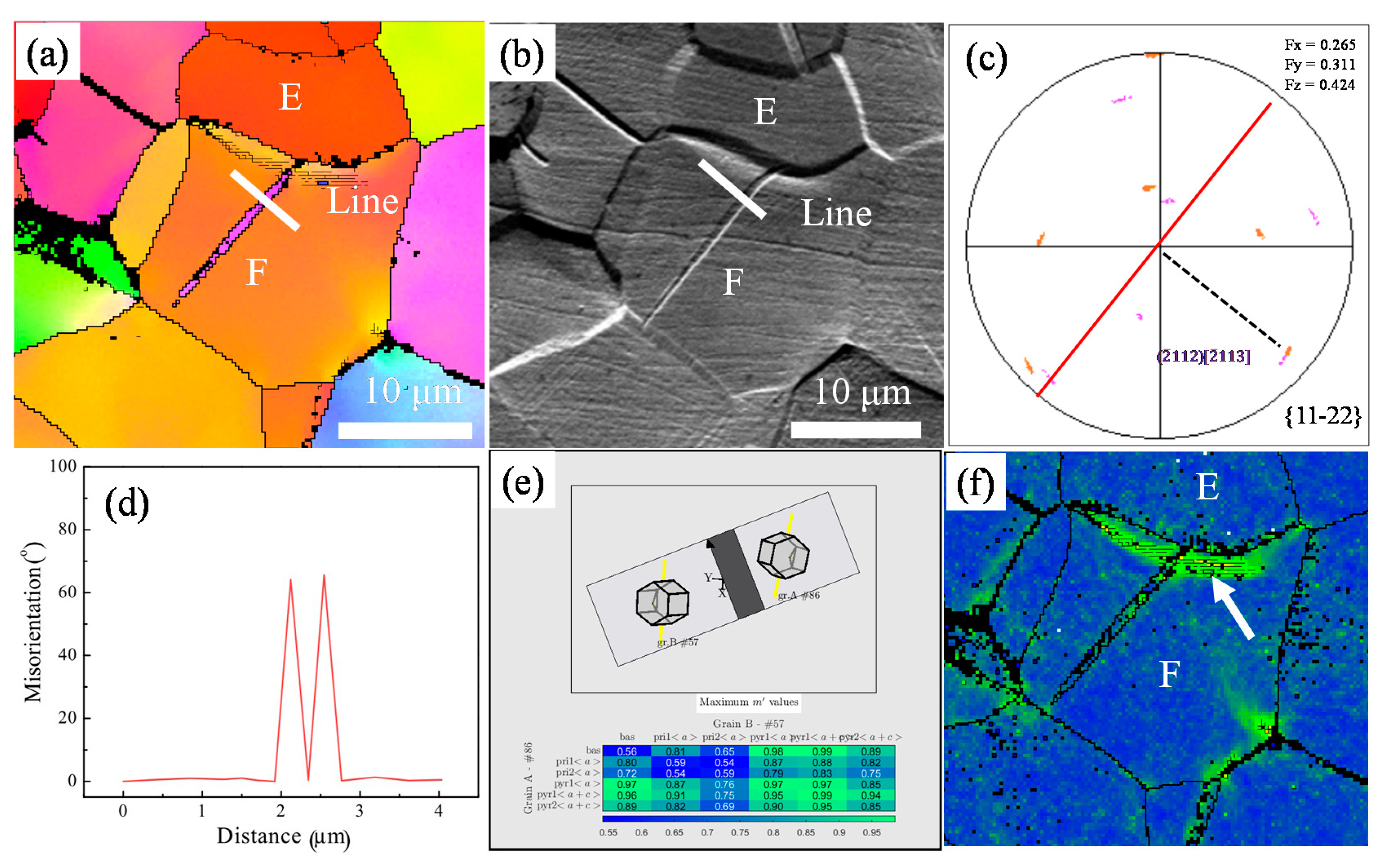
3.3. Deformation Twins during In Situ Tensile Testing

As an important deformation mode in HCP Ti, DTs (including primary twins and secondary twins) were also frequently observed in some grains, as shown in Figure 3a. The misorientations of the primary twins and the secondary twins in the grains are shown in Figure 3b. It can be seen that the misorientation of the primary twin was ~64°, the misorientation of the secondary twin was ~43° relative to the matrix, and the misorientation of the secondary twin relative to the primary twin matrix was ~84°. The variants of the primary twin and secondary twin were determined by pole figure, as shown in Figure 3c,d, respectively. It was determined that the primary twin was the ( 2 ¯ 112) [ 2 ¯ 113] compression twin, and the secondary twin was the (01 1 ¯ 2) [01 1 ¯ 1] tensile twin [29,30].
A larger deformed region was observed to quantitatively analyze the activated deformation mode using slip trace analysis, as shown in Figure 4a,b. The frequency of the activated deformation mode was counted, as shown in Figure 4c. It was revealed that the activated deformation modes were prismatic slip, pyramidal slip, and DTs, and their frequencies were 55%, 21%, and 24%, respectively. This result indicated that prismatic slip is the dominant deformation mechanism, and DTs and pyramidal slip are auxiliary plastic deformation mechanisms.

3.4. Slip Transmission Behavior during In Situ Tensile Testing

Two different cases of slip transmission behavior are shown in Figure 5. In Figure 5b, the slip transmission occurred between grains A and B. The activated slip systems of grain A and grain B were prismatic slips (10 1 ¯ 0) [1 2 ¯ 10] and (1 1 ¯ 00) [11 2 ¯ 0], and their SFs were 0.49 and 0.39, respectively. The m calculation of prismatic slip between grains A and B was highlighted with red wireframe, as shown in Figure 5c, and further observation found that the maximum value of m was 0.94, which indicates that the GB between grains A and B had little obstacle to dislocation slip. In contrast, since the maximum m value of the prismatic slip between grains C and D was only 0.55, the prismatic slip in grain C could not pass through the GB between grains C and D, which resulted in the activation of pyramidal slip in grain D, as shown in Figure 5d–f. The activated slip systems of grains C and D were prismatic slip (1 1 ¯ 00) [11 2 ¯ 0] and first order pyramidal slip (0 1 ¯ 11) [2 11 ¯ 0], and their SFs were 0.40 and 0.32, respectively. Obviously, slip transmission behavior had an influence on the stress concentration and activation of the slip systems. When m was greater than 0.7 (for example, the GB between grains A and B), the slip transmission could effectively coordinate the macroscopic strain. When m was less than 0.7 (for example, the GB between grains C and D), the stress concentration at the GB could be released by the activation of the pyramidal slip system to avoid premature crack nucleation at GBs [31].
Low m induced not only the activity of pyramidal slip but also the nucleation of DTs, as shown in Figure 6. It can be observed that there was no slip activity in grain F and only DT occurred. The DT nucleated from the GB between grains E and F, and this DT was identified as ( 2 ¯ 112) [ 2 ¯ 113] from the IP map and the misorientation distribution in Figure 6c,d. The calculation of SF indicated that the SF of the activated ( 2 ¯ 112) [ 2 ¯ 113] twin was 0.35, and the largest SF of prismatic slip was 0.45. The phenomenon that the ( 2 ¯ 112) [ 2 ¯ 113] twin with high CRSS and low SF was activated instead of prismatic slip with low CRSS and high SF was related to the m value between grains E and F. As shown in Figure 6e, the maximum m of the prismatic slip between grains E and F was 0.61. The poor geometric compatibility between the two grains led to stress concentration at the GB, which was conducive to the nucleation of a DT at the GB [32,33,34,35]. The stress concentration at the GB can be proved by the KAM map, as shown in Figure 6f. It is clear that the intensity of KAM at the GB between grains E and F was obviously higher those that of the other regions, as indicated by the white arrow.

3.5. Surface Topography after In Situ Tensile Testing

The surface topography after an in situ tensile stain of ~22.5% was observed by a confocal laser scanning microscope (CLSM), as shown in Figure 7. Clearly, the surface became rugged due to coordinated deformation between the different grains, and the fluctuation was mainly concentrated at the GB region. Close observation found that the surface bulge was mainly observed at the GBs between grains with slip activity and grains without slip activity. This phenomenon further indicated that, when slip transmission cannot occur at GBs, there is obvious stress concentration at that point [36]. This stress concentration can be released by inducing other deformation modes that are not easy to activate, such as pyramidal slip and DTs. Otherwise, it will develop into crack initiation sites.

4. Conclusions

(1)
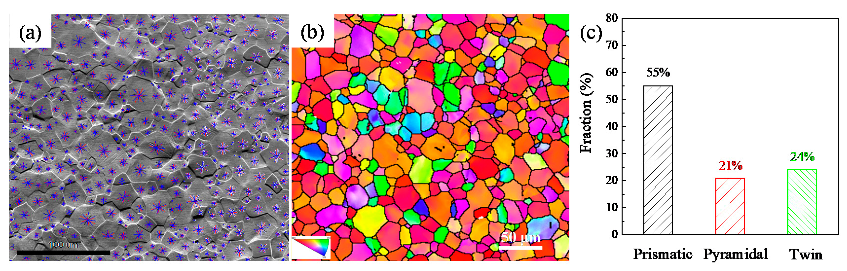
Based on EBSD characterization and slip trace analysis, the active deformation modes of CP-Ti after an in situ tensile strain of ~2.9% were prismatic slip (55%), pyramidal slip (21%), and deformation twins (24%);
(2)
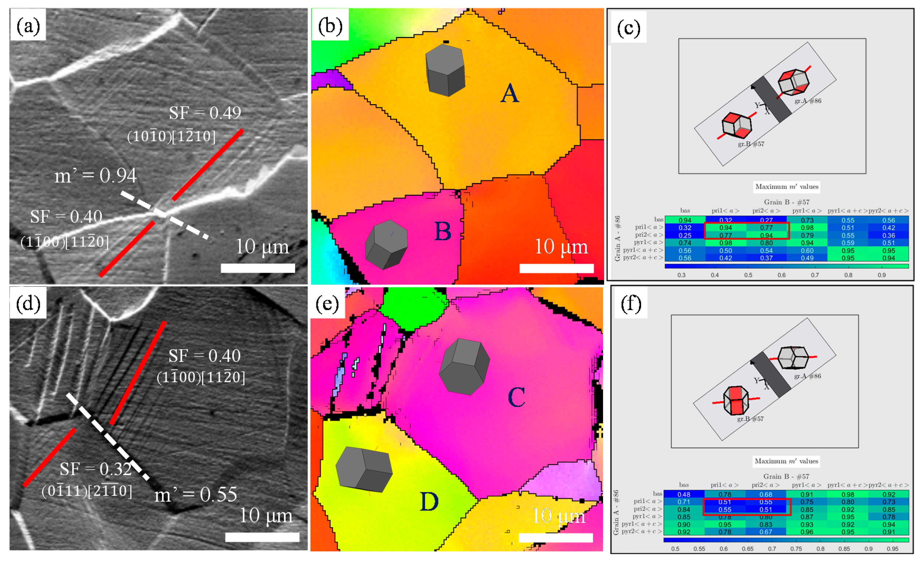
Slip transmission had an obvious influence on the activities of the deformation mode, which were predicted using a geometric compatibility factor. Slip transmission in CP-Ti tended to occur between the same slip types (prismatic slip to prismatic slip). The stress concentration in GBs was released by slip transmission to accommodate coordinated deformation;
(3)
Poor geometric compatibility between two adjacent grains led to stress concentration at the GBs, which was conducive to the activity of pyramidal slip or the nucleation of deformation twins.

Author Contributions

Writing—original draft, C.X.; Writing—review & editing, Q.W.; Funding acquisition, J.R.; Methodology, Y.Z.; Investigation, J.W.; Project administration, J.C.; Formal analysis, L.Z.; Data curation, B.S.; Data curation, L.L. All authors have read and agreed to the published version of the manuscript.

Funding

This project was financially supported by the National Natural Science Foundation of China (Grant No. 52061025), the Technical Innovation Guidance Fund of the Shaanxi Province (2020CGXNX-023), the Natural Science Foundation of the Shaanxi Province (2021JQ-977), the Basic research plan of key scientific research projects of Henan universities (22A430027), and the Natural Science Foundation of the Henan Province of China (202300410280).

Institutional Review Board Statement

Not applicable.

Informed Consent Statement

Not applicable.

Data Availability Statement

Not applicable.

Acknowledgments

All authors would like to thank Wenwu Han from Huanghuai University for his help in samples preparation.

Conflicts of Interest

The authors declare that there are no commercial or financial relationships that could be considered as potential conflict of interest.

References

  1. Zeng, L.; Wang, L.; Hua, P.; He, Z.; Zhang, G. In-situ investigation of dwell fatigue damage mechanism of pure Ti using digital image correlation technique. Mater. Charact. 2021, 181, 111466. [Google Scholar] [CrossRef]
  2. Liu, X.; Gao, H.; Wu, H.; Pan, H.; Shu, B.; Yang, Y.; Liu, H.; Yang, F.; Zhu, X. Microstructure and texture characteristics of pure Ti with a superior combination of strength and ductility. Mater. Sci. Eng. A 2021, 808, 140915. [Google Scholar] [CrossRef]
  3. Wang, B.; Liu, H.; Zhang, Y.; Zhou, B.; Deng, L.; Wang, C.; Chen, J.; Zhang, Y. Effect of grain size on twinning behavior of pure titanium at room temperature. Mater. Sci. Eng. A 2021, 827, 142060. [Google Scholar] [CrossRef]
  4. Kishida, K.; Kim, J.G.; Nagae, T.; Inui, H. Experimental evaluation of critical resolved shear stress for the first-order pyramidal c + a slip in commercially pure Ti by micropillar compression method. Acta Mater. 2020, 196, 168–174. [Google Scholar] [CrossRef]
  5. Gong, J.; Wilkinson, A.J. Anisotropy in the plastic flow properties of single-crystal α titanium determined from micro-cantilever beams. Acta Mater. 2009, 57, 5693–5705. [Google Scholar] [CrossRef]
  6. Hémery, S.; Tromas, C.; Villechaise, P. Slip-stimulated grain boundary sliding in Ti-6Al-4 V at room temperature. Materialia 2019, 5, 100189. [Google Scholar] [CrossRef]
  7. Bieler, T.; Eisenlohr, P.; Zhang, C.; Phukan, H.; Crimp, M. Grain boundaries and interfaces in slip transfer. Curr. Opin. Solid State Mater. Sci. 2014, 18, 212–226. [Google Scholar] [CrossRef] [Green Version]
  8. Zhao, P.Y.; Shen, C.; Savage, M.F.; Li, J.; Niezgoda, S.R.; Mills, M.J.; Wang, Y.Z. Slip transmission assisted by Shockley partials across α/β interfaces in Ti-alloys. Acta Mater. 2019, 171, 291–305. [Google Scholar] [CrossRef]
  9. Tan, C.; Sun, Q.; Xiao, L.; Zhao, Y.; Sun, J. Slip transmission behavior across α/β interface and strength prediction with a modified rule of mixtures in TC21 titanium alloy. J. Alloys Compd. 2017, 724, 112–120. [Google Scholar] [CrossRef]
  10. Jiang, S.; Jia, Y.; Wang, X. In-situ analysis of slip transfer and heterogeneous deformation in tension of Mg-5.4Gd-1.8Y-1.5Zn alloy. J. Magnes. Alloys 2020, 8, 1186–1197. [Google Scholar] [CrossRef]
  11. Joseph, S.; Bantounas, I.; Lindley, T.C.; Dye, D. Slip transfer and deformation structures resulting from the low cycle fatigue of near-alpha titanium alloy Ti-6242Si. Int. J. Plast. 2018, 100, 90–103. [Google Scholar] [CrossRef]
  12. Luster, J.; Morris, J.M. Compatibility of deformation in two-phase Ti-Al alloys: Dependence on microstructure and orientation relationships. Metall. Mater. Trans. A 1995, 26, 1745–1756. [Google Scholar] [CrossRef]
  13. Zhou, B.; Li, Y.; Wang, L.; Jia, H.; Zeng, X. The role of grain boundary plane in slip transfer during deformation of magnesium alloys. Acta Mater. 2022, 227, 117662. [Google Scholar] [CrossRef]
  14. Wei, S.; Zhu, G.; Tasan, C.C. Slip-twinning interdependent activation across phase boundaries: An in-situ investigation of a Ti-Al-V-Fe (α+β) alloy. Acta Mater. 2021, 206, 116520. [Google Scholar] [CrossRef]
  15. Guan, D.; Wynne, B.; Gao, J.; Huang, Y.; Rainforth, W.M. Basal slip mediated tension twin variant selection in magnesium WE43 alloy. Acta Mater. 2019, 170, 1–14. [Google Scholar] [CrossRef]
  16. Wang, Q.; Ren, J.; Zhang, B.; Xin, C.; Wu, Y.; Ye, M. Influence of microstructure on the fatigue crack growth behavior of a near-alpha TWIP Ti alloy. Mater. Charact. 2021, 178, 111208. [Google Scholar] [CrossRef]
  17. Zhang, Z.; Zhang, P.; Li, L. Fatigue cracking at twin boundaries: Effects of crystallographic orientation and stacking fault energy. Acta Mater. 2012, 60, 3113–3127. [Google Scholar] [CrossRef]
  18. Zhang, S.; Zeng, W.; Zhao, Q.; Ge, L.; Zhang, M. In situ SEM study of tensile deformation of a near-β titanium alloy. Mater. Sci. Eng. A 2017, 708, 574–581. [Google Scholar] [CrossRef]
  19. Huang, S.; Zhao, Q.; Lin, C.; Wu, C.; Zhao, Y.; Jia, W.; Mao, C. In-situ investigation of tensile behaviors of Ti–6Al alloy with extra low interstitial. Mater. Sci. Eng. A 2021, 809, 140958. [Google Scholar] [CrossRef]
  20. Cepeda, C.; Molina, J.; Perez, M. Effect of grain size on slip activity in pure magnesium polycrystals. Acta Mater. 2015, 84, 443–456. [Google Scholar] [CrossRef]
  21. Dichtl, C.; Lunt, D.; Atkinson, M.; Thomas, R.; Plowman, A.; Barzdajn, B.; Sandala, R.; da Fonseca, J.Q.; Preuss, M. Slip activity during low-stress cold creep deformation in a near-α titanium alloy. Acta Mater. 2022, 229, 117691. [Google Scholar] [CrossRef]
  22. Bridier, F.; Villechaise, P.; Mendez, J. Analysis of the different slip systems activated by tension in a α/β titanium alloy in relation with local crystallographic orientation. Acta Mater. 2005, 53, 555–567. [Google Scholar] [CrossRef]
  23. Ren, J.; Wang, Q.; Lu, X.; Liu, W.; Zhang, P.; Zhang, X. Effect of oxygen content on active deformation systems in pure titanium polycrystals. Mater. Sci. Eng. A 2018, 731, 530–538. [Google Scholar] [CrossRef]
  24. Wang, L.; Zheng, Z.; Phukan, H.; Kenesei, P.; Park, J.-S.; Lind, J.; Suter, R.; Bieler, T. Direct measurement of critical resolved shear stress of prismatic and basal slip in polycrystalline Ti using high energy X-ray diffraction microscopy. Acta Mater. 2017, 132, 598–610. [Google Scholar] [CrossRef]
  25. Li, H.; Mason, D.; Bieler, T.; Boehlert, C.; Crimp, M. Methodology for estimating the critical resolved shear stress ratios of α-phase Ti using EBSD-based trace analysis. Acta Mater. 2013, 61, 7555–7567. [Google Scholar] [CrossRef]
  26. Shamsujjoha, M.; Agnew, S.R.; Fitz-Gerald, J.M.; Moore, W.R.; Newman, T.A. High Strength and Ductility of Additively Manufactured 316L Stainless Steel Explained. Met. Mater. Trans. A 2018, 49, 3011–3027. [Google Scholar] [CrossRef]
  27. Shamsujjoh, M. Evolution of microstructures, dislocation density and arrangement during deformation of low carbon lath martensitic steels. Mater. Sci. Eng. A 2020, 776, 139039. [Google Scholar] [CrossRef]
  28. Zribi, Z.; Ktari, H.H.; Herbst, F.; Optasanu, V.; Njah, N. EBSD, XRD and SRS characterization of a casting Al-7wt% Si alloy processed by equal channel angular extrusion: Dislocation density evaluation. Mater. Charact. 2019, 153, 190–198. [Google Scholar] [CrossRef]
  29. Zhang, H.; Wei, B.Q.; Ou, X.Q.; Ni, S.; Yan, H.G.; Song, M. Atomic-level study of {101 1} deformation twinning in pure Ti and Ti-5at.% Al alloy. Int. J. Plast. 2022, 153, 103273. [Google Scholar] [CrossRef]
  30. Kumar, M.A.; Beyerlein, I.J. Influence of plastic properties on the grain size effect on twinning in Ti and Mg. Mater. Sci. Eng. A 2020, 771, 138644. [Google Scholar] [CrossRef]
  31. Valeiras, E.; Llorca, J. Criteria for slip transfer across grain and twin boundaries in pure Ni. Materialia 2022, 21, 101303. [Google Scholar] [CrossRef]
  32. Xu, S.; Zhou, P.; Liu, G.; Xiao, D.; Gong, M.; Wang, J. Shock-induced two types of {101 2} sequential twinning in Titanium. Acta Mater. 2019, 165, 547–560. [Google Scholar] [CrossRef]
  33. Capolungo, L.; Beyerlein, I.J.; Tomé, C.N. Slip-assisted twin growth in hexagonal close-packed metals. Scr. Mater. 2009, 60, 32–35. [Google Scholar] [CrossRef]
  34. Wang, L.; Yang, Y.; Eisenlohr, P.; Bieler, T.R.; Crimp, M.A.; Mason, D.E. Twin Nucleation by Slip Transfer across Grain Boundaries in Commercial Purity Titanium. Metall. Mater. Trans. A 2010, 41, 421–430. [Google Scholar] [CrossRef]
  35. Wang, L.; Eisenlohr, P.; Yang, Y.; Bieler, T.R.; Crimp, M.A. Nucleation of paired twins at grain boundaries in titanium. Scr. Mater. 2010, 63, 827–830. [Google Scholar] [CrossRef]
  36. Guan, B.; Xin, Y.; Huang, X.; Liu, C.; Wu, P.; Liu, Q. The mechanism for an orientation dependence of grain boundary strengthening in pure titanium. Int. J. Plast. 2022, 153, 103276. [Google Scholar] [CrossRef]
Figure 1. The initial microstructural characteristics of TA2: (a,b) BC map and the distribution of grain size; (c,d) IPF and cumulative frequency of SF for different deformation modes; and (e,f) KAM map and the frequency distribution of KAM.
Metals 12 00721 g001
Figure 2. The displacement-load curve and the deformed microstructures of TA2 during in situ tensile test: (a) displacement-load curve, (b) SEM image, (c) IPF, (d) KAM map, (e) frequency distribution of KAM, and (f) the geometric compatibility factor ( m ) distribution map of the prismatic slip.
Metals 12 00721 g002
Figure 3. Variant analysis of primary twin and secondary twin: (a) IPF; (b) misorientation between primary twin and secondary twin; (c,d) pole figures (PFs) of primary and secondary twin variants.
Metals 12 00721 g003
Figure 4. The analysis of deformation mechanisms of TA2 after a strain of ~2.9%: (a) SEM with the traces of different deformation modes; the traces of prismatic, basal, and pyramidal planes are indicated by the black, red, and blue lines, respectively; (b) IPF, (c) the fraction of different deformation modes.
Metals 12 00721 g004
Figure 5. Slip transmission behavior between different grains: (a,d) SEM with the slip trace and SF of the activated slip systems; (b,e) IPF; (c) m calculation between grains A and B; (f) m calculation between grains C and D.
Metals 12 00721 g005
Figure 6. The nucleation of DT was induced by stress concentration at the GB: (a) IPF, (b) SEM, and (c) PF of { 11 2 ¯ 2 } ; (d) the distribution of misorientation along the line in (a,e); the calculation of m between grains E and F; and (f) KAM map.
Metals 12 00721 g006
Figure 7. The surface topography of CP-Ti after in situ tensile stain of ~22.5%: (a) the optical microstructure, and (b) the corresponding two-dimensional surface topography.
Metals 12 00721 g007
Table 1. Chemical composition of the experimental material (wt.%).
ElementFeSiCNHOTi
Composition0.30.150.10.050.0150.2Balance
Publisher’s Note: MDPI stays neutral with regard to jurisdictional claims in published maps and institutional affiliations.

