Abstract
This paper represents the fabrication and characterization (microstructural, mechanical, and electrical) of Cu-2wt% B-4 wt% Ti and Cu-5wt% B-10wt% Ti alloy from the ball-milled Cu, Ti, and B powders. The in situ formation of TiB2 was also discussed in the light of differential scanning calorimetry (DSC) and X-ray diffraction (XRD). This present work investigates the effect of various parameters on powder production and the formation of in situ TiB2 through the thermo-mechanical route. The apparent activation energy during metastable phase formation for the two types of alloy composites has been calculated using the Johnson-Mehl-Avramani (JMA) equation and found to be 567.46 and 626.37 (KJ/mol), respectively. However, the findings of this study indicate the mechanical properties of the composite are due to the in situ formation of TiB2 particles in the Cu matrix. The properties of the composites after heat treatment were discussed employing mechanical and electrical properties and measured ultimate tensile strength (UTS) (~375 MPa), yield strength (~300 MPa), and hardness (~150 Hv) for a higher percentage of Ti and B addition. The electrical conductivity also decreased to 53% IACS as Ti negatively impacts conductivity.
1. Introduction
Among the various interesting properties of Cu, high electrical and thermal conductivity and excellent erosion resistance [] are broadly utilized in electric contacts and resistance welding cathodes []. The restrictions of Cu with low strength at room and elevated temperatures [] and low hardness compel their applications. However, valiant attempts have been made to overcome or improve the applicability by processing through Cu-based composites in recent years []. One of the newly explored and promising routes that has emerged is the introduction of hard ceramic particles into the Cu lattice, making them mechanically empowered without much reduction in conductivity. A change in mechanical properties with superior conductivity can be accomplished by introducing ceramic particles into a Cu lattice.
The mechanical quality of Cu can be expanded by age solidifying or fusing non-metallic second-stage particles, for example, oxides and borides, in its grid [,] using several processing routes such as hot pressing or hot pressing preceded by mechanical alloying [,], melting and “in situ” synthesis [], casting process [], spray forming process combined with melting, and hot extrusion []. For introducing such carbides and borides to the Cu matrix to enhance the properties, there are two possible ways in powder metallurgy routes: (a) ex situ, in this process, reinforcement particles are externally added to the Cu matrix [] and (b) in situ, this procedure involves internally introducing the reinforcement via a chemical reaction []. The in situ process has several advantages with fine reinforcement particle formation to achieve better and clean surfaces []. Many researchers have documented that the in situ formation of reinforcement to the Cu matrix magnifies the mechanical and physical properties of Cu matrix composites [,]. Compared with other ceramic particles, such as carbides, nitrides, and oxide, TiB2 has a higher hardness value (HV: 34 GPa), higher elasticity modulus (574 GPa), better conductivity (14.4 µm cm), and thermodynamic stability [], making it a candidate material as reinforcement in Cu-based composites.
Current powder manufacturing techniques have made the Cu–Ti alloy system the most promising for specific applications. From the already acknowledged strengthening mechanisms of Cu–Ti alloys through the formation of metastable Cu4Ti particles, it is assumed that supplementary beneficial results might be carried out by including a third reinforcement material. Boron was selected because it is known that the presence of dispersed TiB2 particles in a Cu matrix does not affect the coefficients of electrical and thermal conductivity to any great extent. B addition should be applied to adjust the grain boundary strengthening since B can be effectively isolated at the grain boundary of Cu []. There are a few reports on the expansion of B to the Cu–Ti alloys framework: Sobhani et al. indicated that enormous particles of TiB2 were situated at the grain boundary in the Cu–1Ti–1TiB2 (wt.%) compound, which was set up by liquefying []; Furuta et al. showed that the Cu–4Ti (wt.%) combinations containing 0.2–1.0 wt.% B, in which TiB2 particles were scattered, had a smaller measure of cell broken hastens than traditional Cu–Ti composites []. These reports suggest that the expansion of B can stifle the development of irregular accelerates in the age-hardenable Cu–Ti alloys, even though the impact of B expansion is yet to be clarified. In the previously mentioned reports, B in the Cu–Ti composites must be circulated in the framework as a solute component, just as in the TiB2 compound. In this way, it is hard to look at the commitment of B to every conveyance. This examination explores the impacts of the appropriation of natural B in the network on microstructural advancement during milling and sintering.
Mechanical alloying (MA) is nothing but a typical powder metallurgy process to produce ceramics, nanomaterials, and alloys [,,,]. The most common mechanical alloying process involves a planetary ball-milling machine. The milling process can be dry or wet, primarily based on the form of substances being milled. Dry milling may be executed with inert gases and, often, nitrogen. On the other hand, wet milling may be performed using toluene [,]. A proper milling process can enhance solid solubility and atomic interdiffusion [,], which is more favorable for in situ formation. Mechanical milling involves using forces such as compressive force, shear, or the effect of particle size reduction of bulk materials. Ball milling of powder particles as a way to synthesize new materials has been advanced as a business method to supply new alloys and phase combinations because it was efficaciously employed in 1970 []. This powder metallurgical technique guides alloys and composites which cannot be synthesized via traditional routes. In nano-materials studies, this approach is nicely used to fine-tune the grain sizes of the substances in nano-scales. The nano-sized powder material is received by repeated mechanical deformation and alloying because the powder is vigorously shaken in a vial or jar containing several milling balls. The electricity switch to the powder debris in these generators occurs with a shearing movement or effect of the excessive-speed balls with the powder.
Clearly, existing literature falls short in presenting a systematic study on the mechanism of formation of in situ TiB2 nano-sized precipitates through the powder metallurgy route. Therefore, the main goal of the prevailing work is to produce an in situ TiB2 composite from Cu with Ti and B metal powders via a high-energy ball-milling method and to investigate their formation mechanism. Understanding the size and lattice strain has accomplished the assets of the produced Cu powder with X-ray diffraction (XRD). The phases and particle size have been analyzed employing scanning electron microscopy (SEM). A transmission electron microscope (TEM) was used to reveal the selected area diffraction (SAD). Additionally, the electrical and mechanical properties were studied by mechanical testing. The effect of Ti and B content on the alloy was investigated, and a mechanism for how Ti interacts with B was discussed.
2. Materials and Methods
2.1. As-Received Powders and Compaction
Cu–TiB2 composites have been fabricated using the powder metallurgy (P/M) route in the present investigation. The cylindrical shaped (Figure 1) shows the real image of the samples after cold compaction (1.a) and after heat treatment (1.b). Cu powder (99% pure), having an average grain size of (45 ± 1 μm), was produced by the electrolytic method and was purchased from Loba Chemie®, Mumbai, India. The elemental Ti and B powders possess a particle size below 140 mesh (105 μm) and have a purity level of 99% procured from Loba Chemie, Mumbai, India. The powders were ball milled (Retsch Planetary Ball Mill PM 400, Retsch, Haan, Germany) to form mixtures of Cu-2%B-4%Ti (wt%) and Cu-5%B-10%Ti (wt%) powders. Mechanical alloying was executed for 26 h in a water-cooled cylindrical container maintaining a rotational speed of 300 rpm. Both containers and the balls consist of austenitic stainless steel. The balls had a 10 mm diameter in size, and the ball-to-powder weight ratio was 30:1. The powder mixtures were cold compacted with 15 ton pressure allowing a holding time of 2 min. The compacted samples were then heat-treated at 800 °C for 1 h and quenched immediately with water. To ensure the development of in situ TiB2 in the Cu matrix, a higher ball-milling duration with a low powder ratio was chosen.
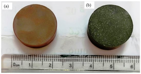
Figure 1.
Real images of the samples (a) after cold compaction; (b) after heat treatment.
On the other hand, the heat treatment cycle significantly influences in situ production. The phase constitution of the quenched specimen for the Ti–B–Cu system is documented as CuTi2, Cu3Ti, Cu4Ti3, Cu4Ti, Cu, and TiB2 []. A higher cooling rate can be developed TiB2 in the Cu matrix, so water quenching is performed immediately after heat treatment.
2.2. Characterization of the As-Received Powders and Compacts
Characterization of the as-received powders was performed by X-ray diffractometer (XRD) (Model—D8 Advance, BRUKER, Germany), and the phases were determined using X-pert high score plus software (Panalytical 3.0.4, Netherland), field emission scanning electron microscopy (FESEM) (JEOL, JSM-7610F, Japan), and high resolution transmission electron microscopy (HRTEM) (JEOL, JEM—2100F, Japan). X-ray diffraction (XRD, Bruker, Germany) of the compacts was carried out to reveal the different phases present after compaction, along with the lattice strain and dislocation density. The data were recorded with a D/max-3B diffractometer using Cu Kα radiation (wavelength of 1.5418 Å) and working at 45 kV and 40 mA with a scan rate of 0.02°/s. The compacted samples were also analyzed utilizing optical microscopy (OM) (Zeiss Axiovert 40 Mat®, Germany), scanning electron microscopy (SEM), TEM, and XRD. OM and FESEM were performed following the standard metallographic polishing route to analyze the compacted samples. The samples for examination were organized to a metallographic finish using a series of grinding and polishing procedures. The compacts were polished with polishing paper from 200 to 1200 grit size, followed by a nonferrous coarse and fine cloth, and finally with diamond paste (0.5–1 micron). Optical microscopy (Leica, DM6 FS, Germany) was used for the microstructural characterization of compacted samples. Etching was performed for the compacted samples with a solution of ethanol (120 mL), hydrochloric acid (50 mL) and ferric chloride (10 gm) for 5 to 10 s.
The powders and prepared alloy composite samples were characterized by TEM with an acceleration voltage of 300 KeV and beam current of 1 mA. Two different paths for powders and bulk compacted samples were chosen for the sample preparation of TEM. 400 mess size Cu grid was used for powder samples to characterize TEM. On the other hand, several steps were involved in cutting and machining, e.g., electro-discharge machining (EDM) (Eurocut mark I 734, Electronica, India), grinding, polishing, and jet-electro polishing for compacted samples. Firstly, the compact samples were turned into a size of 5 mm × 5 mm × 0.5 mm by wire-cut electrical discharge machining (EDM) and then thinned down to 80 µm by traditional grinding and polishing techniques. Then, a 3 mm diameter rounded foil disk was whipped out. Those punched samples were finally polished via twin jet electropolishing at −25 °C with a working voltage of 35 kV, using a well-known solution of 30% HHO3 in methanol to obtain the final TEM sample.
The thermal stability and changes in the phases of the compacted sample were evaluated using a (PerkinElmer DSC 8000, USA) analyzer. The tests were conducted on the small pieces weighing between 10 to 15 mg. To circumvent unwanted oxidation [] (Kim et al. 2004), a constant flow of nitrogen (N2) gas at a flow rate of 50 mL/min was maintained inside the DSC chamber. The tests were conducted at a heating rate of 10 C/min for the temperature range of 30 to 600 °C using high-purity Cu pans as the reference. The phase formation and activation energy rate for the construction or dissolution of the phases were evaluated using the Johnson-Mehl-Avramani (JMA) equation [].
The mechanical properties of the compacts were evaluated by hardness and tensile tests. The hardness was measured by the Innova Test (VerZus 750 CCD, The Netherlands) universal hardness measurement equipment with a load of 200 gf and a dual time of 15 sec. The average hardness values were taken from at least ten indentations within the margin of ±2% for each sample with a confidence index of 0.92.
The Instron universal testing machine (5900 series model) was used to analyze the tensile properties of the composite materials at room temperature (RT). The tests were conducted at a strain rate of 10−3/s and an equivalent cross-head speed of 0.5 mm/min, according to Alaneme and Sanusi [], using a specimen with a diameter of 5 mm and a gauge length of 30 mm. The sample configuration, test procedures, and the basis for determining the tensile properties are in accordance with the ASTME8M-04 [,] standard. The electrical conductivity of each sample was calculated using a digital conductivity meter (Sigma 2008B1, China) at the frequency range of 60 kHz and a working temperature of 20 °C.
3. Microstructure of the Composites
3.1. Optical Micrograph
Figure 2 depicts the optical micrographs of an immaculate Cu–Ti-B metal powder composite. The micrograph shows a uniform distribution of Ti and B within the composites conjointly, and the sporadic particles are consistently disseminated in the Cu lattice. It was noted that more Ti and B particles are on the surface at the higher support of TiB2 formation. This may be due to the contrast between the densities of Cu, Ti, and B. The formation of TiB2 is more favorable than other compounds as solvencies of Ti and B are more than Cu. So, legitimate dissemination and blending of Ti and B in the Cu lattice may be a significant challenge. It was also noted that a few agglomerations occur at the higher substance of Ti and B, primarily described as an agglomeration of the TiB2 compound.
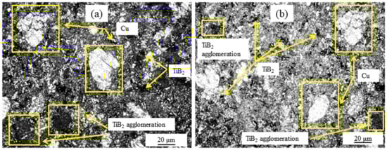
Figure 2.
Optical microstructure of two types of composite: (a) Cu-2 wt% B-4 wt% Ti; (b) Cu-5 wt% B-10 wt% Ti.
The microstructure of the processed composite material also denotes the attendance of TiB2 in the Cu matrix. The Cu grains solidify, circumventing the TiB2 particles, where TiB2 strikes as a nucleus. Uniformly distributed TiB2 particles were optically discerned in the structure, which could probably be reasoned as a ball-milling operation. While sintering, the particles spread uniformly in the matrix. Ti and B atoms are obtained from Cu4Ti and CuB2, respectively, which are the intermediary outputs of the reaction between Cu, Ti, and B during heat treatment. B atoms are pulled towards Cu4Ti particles. The reaction occurs between Ti and B atoms in the interval between sintering, resulting in TiB2 formation. As the B atoms are small in nature, they become facilely diffused through TiB2 particles. The evacuating of Cu4Ti particles naturally develops according to the natural cracking and breaking down characteristics of Cu4Ti particles. These phenomena increase the probability of the development of TiB2 in the Cu matrix [].
3.2. Scanning Electron Microscopy
SEM is performed to reveal the particle size reduction from its as-received elemental state to the compacted one. From Figure 3, it can be found that the Cu particles are dendritic in nature. Ti and B are primarily angular in form. The size of the as-received powder particles is reduced to nanometer-scale after 26 h of ball milling. The final shapes of the particles are primarily sub-granular and rough surfaces are seen in Figure 4. The increment in B substance improves the possibility of agglomerations since the overabundance of B powder cannot blend adequately, as seen in Figure 4b. The higher percentage of Ti has been calculated in the EDX spectra, which shows a higher chance of formation of TiB2.
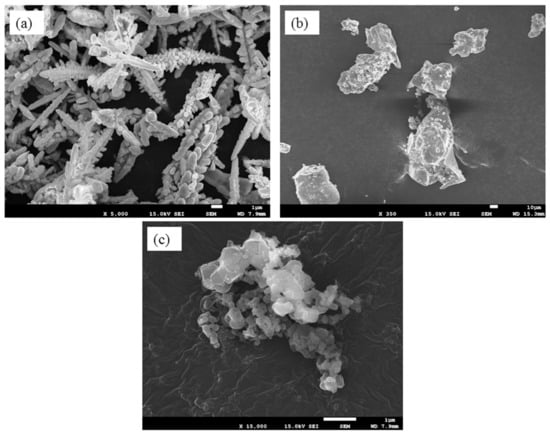
Figure 3.
SEM micrograph of (a) as-received Cu, (b) Ti, and (c) B powder.
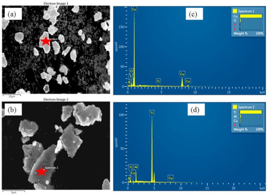
Figure 4.
SEM of the two types of ball-milled powder: (a) represents Cu-2 wt% B-4 wt% Ti and (b) Cu-5 wt% B-10 wt% Ti; (c,d) represent corresponding EDX spectra taken on the red star position.
Figure 5 represents the regional EDS with the mapping of two types of alloy composites. From the EDS analysis, the main matrix and reinforcement elements were determined. The structure spectrum demonstrates and supports TiB2 formation as in situ, which corroborates with TEM investigation [,].
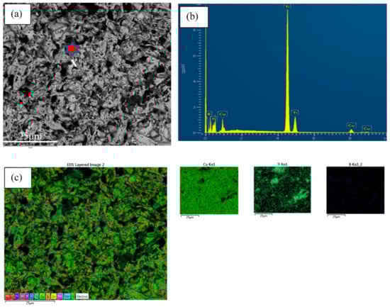
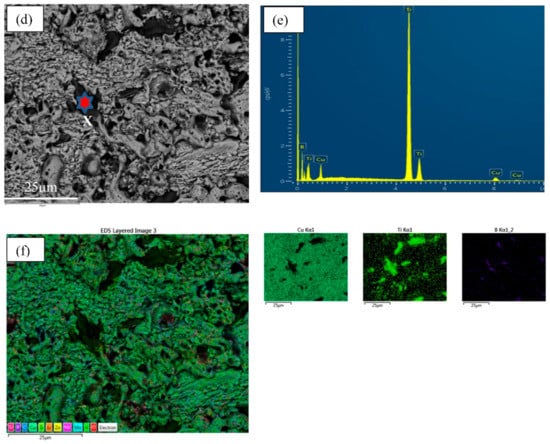
Figure 5.
EDX with mapping taken on the red star position of two types of alloy composites (a–c) for Cu-2B-4Ti and (d–f) for Cu-5B-10Ti.
3.3. Transmission Electron Microscope
Figure 6 illustrates the dark-field image of the Cu, Ti, and B metal powder after the ball milling of 26 h. At the end of the milling process, the grain size distributions of the ball-milled samples are seen to be relatively narrower. The corresponding diffraction pattern is given in the upright inset of the figure. It exhibits that the nano-crystallites structure in the ball-milled samples is distributed randomly and consists of a primarily Cu-rich phase as shown in Figure 7. The grain size is projected from TEM images to be about 10–20 nm, which is in decent agreement with the value found from the broadening of XRD peaks, as plotted in Figure 8.
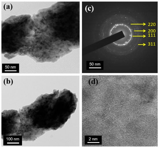
Figure 6.
TEM micrograph of ball-milled powder (Cu-5 wt% B-10 wt% Ti): (a,b) represents overall bright-field images; (c) electron diffraction pattern measured on the nanoparticle; (d) lattice fringes of the powder.
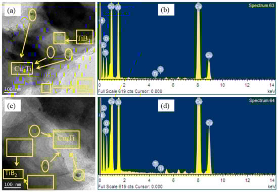
Figure 7.
TEM of two types of the composite after heat treatment: (a) for Cu-2B-4Ti and (c) for Cu-5B 10Ti; (b,d) denotes their EDX, respectively.
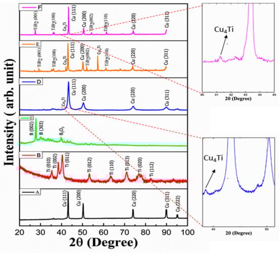
Figure 8.
XRD of (A) pure Cu, (B) Ti, (C) B, (D) milled powder with composition (Cu-5B-10Ti), (E) compacts with composition Cu-2B-4Ti, and (F) Cu-5B-10Ti.
The impact of heat treatment on the composite microstructure was assessed by TEM. Figure 7 provides a TEM picture of the composite with a bounce proportion outline of components through electron energy loss spectroscopy (EELS) after 1 h of heat treatment at 800 °C. As seen in this figure, the accumulation of Ti was not totally in arrangement with the B particles. This dissemination of components inside the lattice shows that fast cooling may stifle the chemical response between Cu and Ti molecules and, subsequently, the arrangement of Cu4Ti particles in Cu. In other words, as the in situ arrangement of TiB2 particles in liquid Cu could be a time-consuming response due to being controlled by the dissemination of B through liquefying micelles interfacing, a portion of B may be cleared out inside the network after fast-hardening. Amid heat treatment of composite at 800 °C, B and Ti particles can respond with each other.
3.4. X-ray Diffraction
Figure 8 shows the XRD pattern of elemental powders and two types of composites after compaction. From Figure 4d, it is observed that there is a formation of an intermetallic phase (Cu4Ti) after 26 h of milling, which corroborates the investigation of Qiang et al. []. X-ray peak broadening shows demonstrated diminishment of the grain estimate down to the nm. Heat treatment is the vital significance for microstructure formation. The contact between the particles of the re-agents and the framework is enhanced within the network during heat treatment. The high conductivity of Cu response is viable during heat reaction. This impact favors the development of the fine particles of titanium diboride [], as shown in Figure 6.
3.4.1. Characteristics of the In Situ Formation Mechanism of TiB2
TiB2 was not synthesized during milling for 26 h whenever TiCu4 was formed, which relates to DSC analysis of milled powder and is superseded by TiB2 during subsequent cold compaction and heat treatment. Reportedly, TiB2 is more stable thermodynamically compared to TiCu4 []. The electron microprobe with area mapping of a compacted sample after milling for 26 h and pressing and heat treatment at 800 °C for 1 h shows that the B segregation is near but not precisely associated with areas of high Ti concentration (Figure 4b). This denotes that Ti still subsisted in the form of a Ti/Cu alloy rather than a Ti/B compound, which is consistent with the antecedent optical discernments by XRD (Figure and DSC). After milling for 97.2 ks and cold pressing at room temperature with heat treatment, the B segregation has an optically discerned temperature and a maximum solubility of about 0.05 wt% to be precisely aligned with the Ti high-rich areas at 800 °C; Ti has a solubility of about 0.55 wt% in Cu at which be tokens that TiCu4 has been converted into TiB2, as substantiated by XRD (Figure 8). Mechanical alloying has enhanced the in situ development of TiB2 in the structure, which can be explained by the following reaction:
TiCu4 + 2B = TiB2 + 4Cu
3.4.2. Grain Size, Lattice Strain, and Dislocation Density Measurement
The crystalline size, lattice strain, and dislocation density of pure Cu powder to Cu-10Ti-5B alloy composite have been listed in Table 1. The table shows that the crystalline size and lattice strain gradually increase for pure Cu to Cu-10Ti-5B composite, and dislocation density initially decreases for milled powder but increases with a higher percentage of alloying elements.

Table 1.
Calculation of dislocation density, lattice strain, and crystallite size of pure Cu and milled powder and the two types of alloy composite utilizing XRD.
The grain size and lattice strain of the pure Cu, ball-milled powder and alloy composite samples are calculated using the single line profile analysis (SLPA) technique. The following equations are used for calculating crystalline size, strain, and dislocation density. All high-intensity peaks are taken for grain size and lattice strain measurement.
where β is the full width at half maximum of the peak expressed in radians, λ is the wavelength of the Kα1 used in radiation, and θ is the Bragg angle.
The relationship between dislocation, crystallite size, and lattice strain is addressed to explain the process of the dislocation growth seen in Table 1. In most cases, the rise in dislocation density has been caused by a decrease in crystallite size or increase of lattice strain. The lower staking fault energy (SFE) promotes grain refinement and higher dislocation density [,]. Consequently, the increase in the dislocation density might be attributed to the decreased SFE of Cu (due to mixing with other elements and subsequent compaction), which allows for splitting dislocations into partial dislocations with extensive stacking fault ribbons [,]. The development inside the dislocation in conjunction with the lower lattice strain elaborates with the X-ray diffraction peak height and broadening. It is supposed that the structures were able to be refined with an expanding TiB2 formation in mechanical processing (milling) and additive fabricating techniques of feedstock powders. The decreasing crystallite measure amid the processing preparation can be rationalized on the premise of nearby plastic distortion through dislocation formation and grain deterioration []. The hard TiB2 particles act as deterrents for developing dislocations by Orowan reinforcing, driving incremental dislocation density, and diminishing the framework of the crystallite estimate. As such, the broadening of FWHM for composite powders is recognized with increasing TiB2 division. As anticipated, the structures of composite parts processed from the comparing composite powders also exhibited a refined drift with an expansion of TiB2 particles.
3.5. DSC and Model
Figure 9 shows the DSC curves of the two alloy composites from the Cu–Ti–B system after 26 h of MA and heat treatment, respectively, indicating that samples subject to MA and heat treatment had great importance and exhibited a distinct exothermic peak at 462 °C and 467 °C. In contrast, no distinct endothermic peaks were observed for the two types of composites. From the DSC curve, it can corroborate that Ti atoms are diffused to Cu grains as the temperature increases. This leads to an exothermic reaction, and Cu4Ti [] phase is formed. The intermetallic phase shapes (Ti + xCu = TiCux) compared to the dissemination between Ti and Cu. According to XRD data, we can co-relate that the TiCux is nothing but the intermetallic phase Cu4Ti. Following the DTA examination of Ti–B, Ti–Cu and Ti–B–Cu, it is found that the arrangement of the TiB2 stage is not completed in one step but experiences a temporal process. So, the response of Ti + 2B + xCu = TiB2 + xCu should be isolated concurring to the taking after steps []:
Ti + xCu = TiCux
TiCux + 2B = TiB2 + xCu
Ti + 2B = TiB2
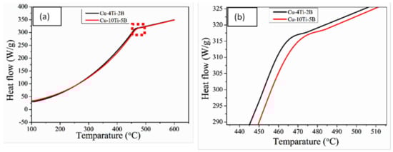
Figure 9.
(a) DSC curve of the two types of alloy composite; (b) zoom of the red block portion.
The rate of phase formation and activation energy required for the construction or dissolution has also been constructed using the Johnson-Mehl-Avramani (JMA) equation. To estimate the kinetics of the two investigated materials, the Johnson-Mehl-Avramani (JMA) equation has been utilized to determine the activation energy for the phase. The modified JMA is expressed by the following formula []:
where is the volume fraction of precipitate at time , is the growth parameter, is the rate of constant, is the activation energy, is a gas constant, and T is the absolute temperature []. The logarithmic form of Equation (8) yields:
As a result, the plot of vs. yields a straight line function, from which the value of (slope) and (intercept) can be determined. In addition, Equation (8) can be employed to explain the non-isothermal transformation, and it was more essential to construct the rate of transformation and related expression. Therefore, the transformation rate can be expressed as:
where is the implicit function of from Equation (8). Now joining the Equation (11) and the derivative of Equation (8), we develop:
On the other hand, the phase transformation peaks in the DSC thermogram are connected to different solid–state reactions over a specific temperature range. The amount of phase formed or dissolved at a given temperature , can be expressed as the ratio of area enclosed by the peak at a temperature and the total area of the peak .
The rate of transformation is linked to a heating rate () for the DSC scan and it can be described by the following equation []:
From the vs. curve in Equation (13), the magnitude of is obtained. In addition, the DSC scan can achieve the activation energy with a single heating rate. The combination of Equations (9) and (14) forms:
Adopting logarithm and rearranging, Equation (15) may be expressed as []:
A straight line of slope can be obtained after plotting vs. and from which the activation energy can be estimated.
In general, for the advancement of thermal reactions at all temperature–time regimes, the function and activation energy ( must be determined. A wide range of standard reaction models have already been explored in the literature [,,] to fit the ffunctionunction . Consequently, the function is calculated by taking suitable forms and can be confirmed with experimental results. A universal relationship that can offer sigmoidal behavior is:
where the exponent r and m are constant. The formula can be associated with (JMAK) kinetics equations and forms the sigmoidal behavior:
where the exponent n is the growth parameter and it is constant. If n is considered to be 1, 3/2, 2 and 3, then Equation (12) is expressed by:
Now, combinations of Equations (8) and (10) can yields:
The pots of vs. are made to confirm the proper function of after fitting any one Equation of (21)–(23).
Formation of Cu4Ti phase
The DSC peak formations of the Cu4Ti phase for the two types of alloy composite are shown in Figure 10. From Equations (13) and (8), the amount (volume fraction,) and rate ( of phase was calculated from the DSC. The plots of ( vs. and ( vs. were the function of temperature and are shown in Figure 9a,b, respectively.
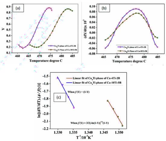
Figure 10.
Estimation amount of (a) phase fraction with temperature, (b) phase rate with temperature, and (c) activation energy for two types of alloy composite for Cu4Ti phase formation.
The ( vs. curve was sigmoidal and steadily shifted to a lower temperature for Cu-4Ti-2B alloy, followed by Cu-10Ti-5B alloy. Additionally, there were substantial shifts in the maxima of the rate of transformation curves for the higher percentage Ti and B alloy compared to the lower percentage alloy (Figure 6b). It was understood that the transformation was kinetically controlled after adding Ti, B elements, which increased the kinetics of the formation of the Cu4Ti phase. The plot of vs. from Equation (17) and the slope of this straight line was employed to calculate the activation energy of each phase from Figure 9c. The best fitting of the transformation function for the formation of the Cu4Ti was expressed as and (Equations (13) and (12)) for the composites, respectively. Thus for the formation of the Cu4Ti, the values of were 567.46 and 626.37 (KJ/mol) for the two types of alloy composite with different percentages of Ti added and B added alloy, respectively. This indicated that the lower activation energy of Cu-2B-4Ti-alloy is beneficial for easily forming the Cu4Ti phase.
3.6. Mechanical and Electrical Properties of the Compacts
The mechanical and electrical properties are shown in Figure 11. This figure attributed that with increasing the percentage of Ti and B, the yield strength and ultimate tensile strength increased, but elongation and electrical conductivity decreased in Figure 12 and Figure 13 respectively. The electrical conductivity of the developed composite was assessed during heat treatment, and the outcomes demonstrated that the electrical conductivity of the as-received pure Cu was 96% IACS and decreased up to 53% IACS after the titanium percentage gradually increased Ti altogether, decreasing the electrical conductivity of Cu []. It also stated that the electrical conductivity of the Cu matrix decreases dramatically when Ti content is increased, as Ti has a more significant negative impression on the electrical properties of Cu alloys than other commonly known alloying elements such as Zn, Sn, and Ni. On the other hand, a low amount of Ti does not result in the precipitation of the necessary phases for strengthening CuTi alloys []. The Cu with 10 wt% Ti and 5 wt% B composites appears to have the highest UTS and yield strength against other composites. The hard strengthening quality reinforcement particles acted as a load-bearing component and shared the offered high dislocation strengthening to the lattice composite of its separation reinforcing in Cu framework composite are major vital features for making high strength composite quality.
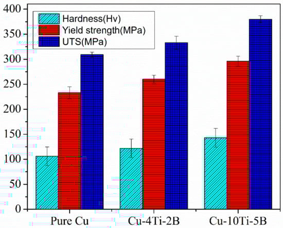
Figure 11.
Hardness, Yield strength and UTS of pure Cu and the composites.
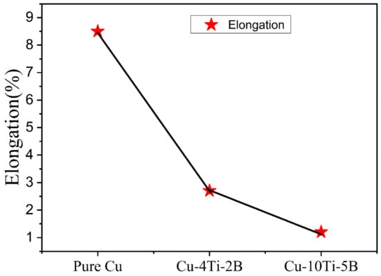
Figure 12.
Elongation of pure Cu with two types of composites.
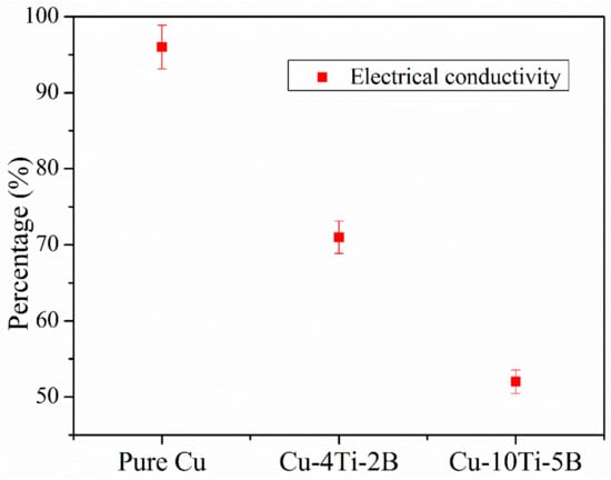
Figure 13.
Electrical conductivity of pure Cu with two types of composites.
The results of microhardness measurements of powder-compacted samples milled for 26 h time periods followed by heat treatment are shown in Figure 11. After ball milling and heat treatment, the hardness of Cu-5B-10Ti- alloy reaches 150 Hv. The powder had a sharp incline after 26 h of milling due to the formation of the complex amorphous phase, in agreement with XRD results (Figure 8). The hardness value increased from 100 to 150 for pure Cu to Cu-5B-10Ti. There are significant differences between the hardness of Cu-2B-4Ti and Cu-5B-10Ti. Because of this outcome, it could be contemplated that the reinforcement particles can obstruct the development of dislocations in the composite. In this way, greater support particles in the grid may correspondingly obtain more prominent increment hardness on the enhancement of work hardening. Although all the mechanical properties significantly improved with adding more alloying elements, the elongation drastically decreased from pure Cu to Cu-5B-10Ti composite, as shown in Figure 12. The decrease in the elongation can be summarized as the increment of alloying elements; the ductility decreases accordingly and lowers the elongation [].
4. Conclusions
The following conclusions can be drawn from the results of this present study:
- The formation of in situ TiB2 in the Cu matrix has been successfully developed from Cu, Ti, and B elemental metal powders using ball milling and subsequent cold compaction with heat treatment.
- Cu–Ti–B with higher Ti and B combination exhibited higher mechanical properties such as hardness, yield strength, and UTS but lower elongation and electrical conductivity owing to the fact that Ti has a negative impact on conductivity. B addition develops grain refinement in the age-hardenable Cu–Ti alloys and, hence, attributed to higher hardness.
- XRD examination uncovered an increment within the dislocation density with a increase in lattice strain followed by an increased percentage of Ti and B. The strain reduction was believed to be due to the decrease in the SFE of Cu during mixing and subsequent compaction. The increase in dislocation density is due to the grain subdivision and the arrangement of high-angle grain boundaries with the change in composition. However, the rate of an increment within the disengagement was moderate.
- The TEM investigation of ball-milled powder exhibited a nano-crystalline structure randomly oriented Cu-rich phase, and the average particle size was projected to 10–20 nm. The processed composite structure demonstrated the support of the in situ formation of TiB2.
- With an increment of Ti and B, the microhardness displayed a slight rise and the most extreme esteem of∼150 HV was obtained with the Cu-10Ti-5B alloy composite.
- With a larger amount of Ti and B fraction, UTS (~375 MPa) and yield strength (~300 MPa) values were recorded higher owing to scattering and dislocation strengthening besides the high densification level.
- For the formation of the Cu4Ti phase, the values of activation energy were 567.46 and 626.37 (KJ/mol) for the two types of alloy composite. This indicated that the lower activation energy for Cu-4Ti-2B composite is beneficial for the easy formation of the Cu4Ti phase.
Author Contributions
U.K.M.—experimental work and writing, A.G.—writing and modeling; A.H.S., I.A.A., N.S.A. and H.S.A.—writing, review and editing and M.G.—writing, review and editing. All authors have read and agreed to the published version of the manuscript.
Funding
This research was funded by the Researchers Supporting Project grant number RSP-2021/373].
Institutional Review Board Statement
Not applicable.
Informed Consent Statement
Not applicable.
Data Availability Statement
Not applicable.
Acknowledgments
The authors would like to acknowledge the Researchers Supporting Project number (RSP-2021/373), King Saud University, Riyadh, Saudi Arabia.
Conflicts of Interest
The authors declare no conflict of interest.
References
- Davis, J.R. Cu and Cu Alloys; ASM International: Materials Park, OH, USA, 2001. [Google Scholar]
- Lu, K. The future of metals. Science 2010, 326, 319–320. [Google Scholar] [CrossRef] [PubMed]
- Mingxing, G.; Kun, S.; Mingpu, W. Relationship between microstructure, properties and reaction conditions for Cu–TiB2 alloys prepared by in situ reaction. Acta Mater. 2009, 57, 4568–4579. [Google Scholar] [CrossRef]
- Robbiola, L.; Blengino, J.-M.; Fraud, C. Morphology and mechanisms of formation of natural patinas on archaeological Cu-Sn alloys. Corros. Sci. 1998, 40, 2083–2111. [Google Scholar] [CrossRef]
- Tu, J.P.; Rong, W.; Guo, S.Y.; Yang, Y.Z. Dry sliding wear behavior of in situ Cu−TiB2 nano-composites against medium carbon steel. Wear 2003, 255, 832–835. [Google Scholar] [CrossRef]
- Tjong, S.C.; Lau, K.C. Abrasive wear behavior of TiB2 particle reinforced Cu matrix composites. Mater. Sci. Eng. A 2000, 282, 183–186. [Google Scholar] [CrossRef]
- Ziemnicka-Sylwester, M. Superhard TiB2-based composites with different matrix fabricated from elemental powders by SHS-p-HIP. Adv. Sci. Technol. 2013, 77, 146–152. [Google Scholar]
- Lu, J.; Shu, S.; Qiu, F.; Wang, Y.; Jiang, Q. Compression properties and abrasive wear behavior of high volume fraction TiCx–TiB2/Cu composites fabricated by combustion synthesis and hot press consolidation. Mater. Des. 2012, 40, 157–162. [Google Scholar] [CrossRef]
- Tu, J.P.; Wang, N.Y.; Yang, Y.Z.; Qi, W.X.; Liu, F.; Zhang, X.B.; Lu, H.M.; Liu, M.S. Preparation and properties of TiB2 nanoparticle reinforced copper matrix composites by in situ processing. Mater. Lett. 2002, 52, 448–452. [Google Scholar] [CrossRef]
- Jung, T.K.; Lim, S.C.; Kwon, H.C.; Kim, M.S. Fabrication and properties of TiB2 reinforced Cu composites by electromagnetic stirring. Mater. Sci. Forum 2004, 449–452, 297–300. [Google Scholar] [CrossRef]
- Lee, J.; Jung, J.Y.; Lee, E.S.; Park, W.J.; Ahn, S.; Kim, N.J. Microstructure and properties of titanium boride dispersed Cu alloys fabricated by spray forming. Mater. Sci. Eng. A 2000, 277, 274–283. [Google Scholar] [CrossRef]
- Casati, R.; Vedani, M. Metal Matrix Composites Reinforced by Nano-Particles—A Review. Metals 2014, 4, 65–83. [Google Scholar] [CrossRef]
- Thi Hoang Oanh, N.; Hoang Viet, N.; Kim, J.S.; Moreira Jorge Junior, A. Characterization of In-Situ Cu–TiH2–C and Cu–Ti–C Nanocomposites Produced by Mechanical Milling and Spark Plasma Sintering. Metals 2017, 7, 117. [Google Scholar] [CrossRef]
- Ramesh, M.; Jafrey, D.D.; Ravichandran, M. Investigation on Mechanical Properties and Wear Behaviour of Titanium Diboride Reinforced Composites. FME Trans. 2019, 47, 873–879. [Google Scholar] [CrossRef]
- Zuhailawati, H.; Yong, T.L. Consolidation of dispersion strengthened copper–niobium carbide composite prepared by in situ and ex situ methods. Mater. Sci. Eng. A 2009, 505, 27–30. [Google Scholar] [CrossRef]
- Awotunde, M.A.; Adegbenjo, A.O.; Obadele, B.A.; Okoro, M.; Shongwe, B.M.; Olubambi, P.A. Influence of sintering methods on the mechanical properties of aluminium nanocomposites reinforced with carbonaceous compounds: A review. J. Mater. Res. Technol. 2019, 8, 2432–2449. [Google Scholar] [CrossRef]
- Basu, S.N.; Hubbard, K.M.; Hirvonen, J.P.; Mitchell, T.E.; Nastasi, M. Microstucture and Stability of TiB2 and Cu Multilayers. MRS Online Proc. Libr. 1990, 187, 157–160. [Google Scholar] [CrossRef]
- Laughlin, D.E.; Cahn, J.W. The crystal structure of the metastable precipitate in Cu-based Cu-titanium alloys. Scr. Metall. 1974, 8, 75–78. [Google Scholar] [CrossRef]
- Sobhani, M.; Mirhabibi, A.; Arabi, H.; Brydson, R.M.D. Effects of in situ formation of TiB2 particles on age-hardening behavior of Cu–1 wt% Ti–1 wt% TiB2. Mater. Sci. Eng. A 2013, 577, 16–22. [Google Scholar] [CrossRef]
- Furuta, R.; Sato, T.; Kobayashi, I.; Tezuka, Y. The effects of B addition on discontinuous precipitation of Cu-Ti alloy. J. Jpn. Inst. Copp. 2014, 5, 55–61. (In Japanese) [Google Scholar]
- Abdo, H.S.; Seikh, A.H. Correlation of Microstructure with Compression Behaviour of Al5083/ZrC Nanocomposites Fabricated Through Spark Plasma Sintering. Trans. Indian Inst. Met. 2022, 75, 2273–2280. [Google Scholar] [CrossRef]
- Abdo, H.S.; Abdus Samad, U.; Abdo, M.S.; Alkhammash, H.I.; Aijaz, M.O. Electrochemical Behavior of Inductively Sintered Al/TiO2 Nanocomposites Reinforced by Electrospun Ceramic Nanofibers. Polymers 2021, 13, 4319. [Google Scholar] [CrossRef]
- Abdo, H.S.; Seikh, A.H. Mechanical Properties and Microstructural Characterization of Laser Welded S32520 Duplex Stainless Steel. Materials 2021, 14, 5532. [Google Scholar] [CrossRef] [PubMed]
- Abdo, H.S.; Seikh, A.H.; Fouly, A.; Ragab, S.A. Synergistic Strengthening Effect of Reinforcing Spark Plasma Sintered Al-Zn-TiC Nanocomposites with TiC Nanoparticles. Crystals 2021, 11, 842. [Google Scholar] [CrossRef]
- Almotairy, S.M.; Alharthi, N.H.; Alharbi, H.F.; Abdo, H.S. Superior Mechanical Performance of Inductively Sintered Al/SiC Nanocomposites Processed by Novel Milling Route. Sci. Rep. 2020, 10, 10368. [Google Scholar] [CrossRef] [PubMed]
- Almotairy, S.M.; Sherif, E.-S.M.; Alharthi, N.H.; Abdo, H.S.; Alharbi, H.F.; Luqman, M. Influence of Milling Route on the Corrosion Passivation of Al-2%SiC Nanocomposites in Chloride Solutions. Crystals 2021, 11, 1231. [Google Scholar] [CrossRef]
- Ibrahim, A.M.M.; Shi, X.; Radwan, A.R.; Mohamed, A.F.A.; Ezzat, M.F. Enhancing the tribological properties of NiAl based nano-composites for aerospace bearing applications. Mater. Res. Express 2019, 6, 085067. [Google Scholar] [CrossRef]
- Abdo, H.S.; Seikh, A.H.; Abdus Samad, U.; Fouly, A.; Mohammed, J.A. Electrochemical Corrosion Behavior of Laser Welded 2205 Duplex Stainless-Steel in Artificial Seawater Environment under Different Acidity and Alkalinity Conditions. Crystals 2021, 11, 1025. [Google Scholar] [CrossRef]
- Buschow, K.H.J.; Cahn, R.W.; Flemings, M.C.; Ischner, B.I.; Kramer, E.J.; Mahajan, S. (Eds.) Encyclopedia of Materials: Science and Technology; Elsevier: Amsterdam, The Netherlands, 2001. [Google Scholar]
- Qiang, X.; Xinghong, Z.; Jiecai, H.; Wei, P. The Process of TiB2-Cu Composite Phase and Structure Formation during Combustion Synthesis. J. Wuhan Univ. Technol.—Mater. Sci. Ed. 2006, 21, 113–116. [Google Scholar] [CrossRef]
- Kim, H.S.; Yang, H.S.; Kim, H.J.; Park, H.J. Thermo gravimetric analysis of rice husk flour filled thermoplastic polymer composites. J. Therm. Anal. Calorim. 2004, 76, 395–404. [Google Scholar] [CrossRef]
- Ghosh, A.; Ghosh, M.; Shankar, G. On the role of precipitates in controlling microstructure and mechanical properties of Ag and Sn added 7075 alloys during artificial ageing. Mater. Sci. Eng. A 2018, 738, 399–411. [Google Scholar] [CrossRef]
- Alane, K.K.; Sanusi, K.O. Mechanical and wear behavior of rice husk ash–alumina–graphite hybrid reinforced aluminum based composites. Eng. Sci. Technol. Int. 2015, 18, 416–422. [Google Scholar]
- ASTM E8M-04; Standard Test Methods for Tension Testing of Metallic Materials [Metric]. ASTM International: West Conshohocken, PA, USA, 2004.
- Ghosh, A.; Ghosh, M.; Gudimetla, K.; Kalsar, R.; Kestens, L.; Balasubramanian, R. Development of ultrafine-grained Al–Zn–Mg–Cu alloy by equal channel angular pressing: Microstructure, texture and mechanical properties. Arch. Civ. Mech. Eng. 2020, 20, 7. [Google Scholar] [CrossRef]
- Dinesh, J.; Ashraf, G.M.; Radhika, N. Fabrication and characterization of AL LM25/TIB2 in-situ composites. ARPN J. Eng. Appl. Sci. 2016, 11, 6001–6005. [Google Scholar]
- Zou, C.L.; Chen, Z.N.; Kang, H.J.; Wang, W.; Li, R.; Li, T.; Wang, T. Study of enhanced dry sliding wear behavior and mechanical properties of Cu-TiB2 composites fabricated by in situ casting process. Wear 2017, 392, 118–125. [Google Scholar] [CrossRef]
- Zou, C.; Kang, H.; Wang, W.; Chen, Z.; Li, R.; Gao, X.; Li, T.; Wang, T. Effect of La addition on the particle characteristics, mechanical and electrical properties of in situ Cu-TiB2composites. J. Alloys Compd. 2016, 687, 312–319. [Google Scholar] [CrossRef]
- Kim, J.S.; Kwon, Y.S.; Lomovsky, O.I.; Dudina, D.V.; Kosarev, V.F.; Klinkov, S.V.; Kwon, D.H.; Smurov, I. Cold spraying of in situ produced TiB2–Cu nanocomposite powders. Compos. Sci. Technol. 2007, 67, 2292–2296. [Google Scholar] [CrossRef]
- Bozie, D.; Mitkov, M. Formation of a TiB2-Reinforced Copper-Based Composite by Mechanical Alloying and Hot Pressing. Mater. Sci. Technol. 1992, 8, 1108–1115. [Google Scholar]
- Sandlobes, S.; Friak, M.; Zaefferer, S.; Dick, A.; Yi, S.; Letzig, D.; Pei, Z.; Zhu, L.-F.; Neugebauer, J.; Raabe, D. The relation between ductility and stacking fault energies in Mg and Mg–Y alloys. Acta Mater. 2012, 60, 3011–3021. [Google Scholar] [CrossRef]
- Miyajima, Y.; Abe, H.; Fujii, T.; Onaka, S.; Kato, M. Effects of Si on mechanical properties and microstructure evolution in ultrafine-grained Cu–Si alloys processed by accumulative roll bonding. Acta Mater. 2013, 61, 1537–1544. [Google Scholar] [CrossRef]
- Abdo, H.S.; Seikh, A.H.; Mandal, B.B.; Mohammed, J.A.; Ragab, S.A.; Abdo, M.S. Microstructural Characterization and Corrosion-Resistance Behavior of Dual-Phase Steels Compared to Conventional Rebar. Crystals 2020, 10, 1068. [Google Scholar] [CrossRef]
- Fattah-alhosseini, A.; Keshavarz, M.K.; Mazaheri, Y.; Ansari, A.R.; Karimi, M. Strengthening mechanisms of nano-grained commercial pure titanium processed by accumulative roll bonding. Mater. Sci. Eng. 2017, 693, 164–169. [Google Scholar] [CrossRef]
- Alizadeh, A.; Taheri-Nassaj, E.; Baharvandi, H.R. Preparation and investigation of Al–4 wt% B4C nanocomposite powders using mechanical milling. Bull. Mater. Sci. 2011, 34, 1039–1048. [Google Scholar] [CrossRef]
- Hesabi, Z.R.; Kamrani, S.; Simchi, A. Reihani SMS. Effect of nano scaled reinforcement particles on the structural evolution of aluminum powder during mechanical milling. Powder Metall. 2009, 52, 151–157. [Google Scholar] [CrossRef]
- Dong, S.J.; Zhou, Y.; Shi, Y.W.; Chang, B.H. Formation of a TiB2-Reinforced Cu-Based Composite by Mechanical Alloying and Hot Pressing. Metall. Mater. Trans. A 2002, 33, 1275–1280. [Google Scholar] [CrossRef]
- Ghosh, K.S.; Gao, N. Determination of kinetic parameters from calorimetric study of solid state reactions in 7150 Al-Zn-Mg alloy. Trans. Nonferrous Met. Soc. China 2011, 21, 1199–1209. [Google Scholar] [CrossRef]
- Nagarjuna, S.; Balasubramanian, K.; Sarma, D.S. Effect of Ti additions on the electrical resistivity of Cu. Mater. Sci. Eng. A 1997, 225, 118–124. [Google Scholar] [CrossRef]
- Nagarjuna, S.; Srinivas, M.; Balasubramanian, K.; Sarma, D.S. On the variation of mechanical properties with solute content in Cu−Ti alloys. Mater. Sci. Eng. A 1999, 259, 34–42. [Google Scholar] [CrossRef]
- Kwon, D.H.; Nguyen, T.D.; Dudina, D.; Kim, J.S.; Yum, Y.J.; Kwon, Y.S. Properties of dispersion strengthened Cu-TiB2 nanocomposites prepared by spark plasma sintering. Solid State Phenom. 2007, 119, 63–66. [Google Scholar] [CrossRef]
Publisher’s Note: MDPI stays neutral with regard to jurisdictional claims in published maps and institutional affiliations. |
© 2022 by the authors. Licensee MDPI, Basel, Switzerland. This article is an open access article distributed under the terms and conditions of the Creative Commons Attribution (CC BY) license (https://creativecommons.org/licenses/by/4.0/).