Article

Numerical Analysis of Natural Gas Injection in Shougang Jingtang Blast Furnace

1
School of Metallurgical and Ecological Engineering, University of Science and Technology Beijing, Beijing 100083, China
2
Shougang Jingtang Iron and Steel Co., Ltd., Tangshan 063200, China
*
Authors to whom correspondence should be addressed.
Metals 2022, 12(12), 2107; https://doi.org/10.3390/met12122107
Submission received: 27 October 2022 / Revised: 29 November 2022 / Accepted: 2 December 2022 / Published: 8 December 2022
(This article belongs to the Special Issue Mathematical Modelling of the Ironmaking Blast Furnace)

Abstract

:
A static model of blast furnace operation of natural gas (NG) injection was developed. The effect of NG injection on the raceway adiabatic flame temperature, the amount and composition of bosh gas, the direct reduction degree and fuel ratio were studied. The results showed that under no thermal compensation, the heat loss of the whole blast furnace increases, which means the heat surplus of the whole furnace is sufficient. However, the heat in the high-temperature zone of the blast furnace is insufficient, showing the characteristics of “cold at bottom and hot at the top”. Based on the comparison of heat loss in the high-temperature zone after NG injection with the reference condition, if the heat loss is consistent with the reference case, the suitable NG injection volumes are 17.3, 34.6, 52 and 69.3 m3/t when the coal ratio is reduced by 20, 40, 60 and 80 kg/t, respectively. With the increase of the suitable NG injection volumes, the adiabatic flame temperature gradually decreases, the amount of bosh gas slightly increases, and the overall fuel ratio reduces gradually. The effect of other thermal compensation operations, such as increasing blast temperature and addition of oxygen on the NG injection, were also investigated. The findings of this work can be used as a theoretical basis to guide plant operations for NG injection in blast furnaces.

1. Introduction

The “Blast furnace (BF)-LD Converter” process is the dominant steelmaking route in the world. Among this process, the BF occupied 50% of energy consumption and 60% of GHG emission in the iron and steel sector [1,2]. Natural gas (NG) is an excellent resource with high hydrogen and high calorific value [3]. Blast furnace NG injection plays a great advantage in reducing solid fuel consumption, reducing CO2 emissions, and realizing clean production, which has been regarded as an effective means of low carbon ironmaking.
In 1957, Petrovsky Plant in the former Soviet Union implemented NG injection in blast furnace for the first time and achieved good results. During the period of NG injection from 1959 to 1966, the coke rate decreased by 7–14%, while the production increased by 4–7% [4]. By the end of the 1980s, 112 of the 133 blast furnaces in the former Soviet Union had implemented NG injection, with an annual injection volume of 1200 m3, about 70–100 m3/tHM [5]. In the 1980s, due to the massive extraction and efficient delivery of NG in the world, as well as relatively stable prices, NG injection in blast furnaces in North America was rapidly developed, with an injection about 55–139 m3/t, up to 216 m3/t [6,7]. In 2004, Japan’s Kyohama No.2 blast furnace carried out the industrial practice of NG injection. When the blast volume and the raceway adiabatic flame temperature (RAFT) remained unchanged, the oxygen enrichment rate increased from 4.7% to 5.6%, realizing a NG injection volume of 50 kg/t, about 70 m3/t. The overall utilization coefficient of the blast furnace increased from 2.34 t/m3d to 2.52 t/m3d [8].
The data of the blast furnace NG injection were rarely released in China. However, to reduce CO2 emissions and ease the total coal consumption limit, the NG injection in blast furnaces has begun to gain attention. In fact, the earliest practice of blast furnace NG injection in China can be traced back to Chonggang in the 1960s. In 1965, Chongqing Iron and Steel Group Co., Ltd. conducted NG injection on its 3# blast furnace. The blast temperature was 1070 °C, the humidity was 18.6 g/m3, and the natural gas injection volume reached 96 m3/t without oxygen enrichment. During injection, the coke ratio was reduced from 802 kg/t to 667 kg/t by 16.9%, the replacement ratio was about 1.41 kg/m3, and the utilization coefficient of blast furnace is increased from 1.06 t/m3d to 1.24 t/m3d. Due to the subsequent tight supply of NG, the NG injection in Chonggang’s blast furnace was forced to stop [9]. Baosteel completed the practice of injecting NG into a blast furnace in October 2020, replacing traditional solid fuel with clean energy to save coal and reduce CO2 emissions. China is rich in coke oven gas (COG) resources and has a wealth of practical experience in COG injection [10,11]. A series of numerical models were developed to study the influence of blast furnace COG injection on coke ratio, output, heat balance, and other factors [12,13,14,15]. These works are useful for understanding reducing gas injection in blast furnace. However, NG, with more CH4 content, has a stronger cooling effect on the raceway zone, and it is more difficult to realize the thermal compensation measures. Previous study has shown that the RAFT decreases 45 °C with every increase of 10 kg/t NG injection in the blast furnace, which requires that the RAFT should be adjusted by reasonable blast furnace operation to meet the requirements of stable smooth operation of the blast furnace [16]. Although there are some simulation studies about the influence of NG injection on the multiphase transport behavior in raceway and in the whole blast furnace [17,18,19], the information about the effect of thermal compensation measures on the NG injection in blast furnace need further study.
In this work, based on the actual operation data of the Shougang Jingtang 5500 m3 blast furnace, a static model of blast furnace operation of NG injection was developed to theoretical study the NG injection in blast furnace. The influences of NG injection with no thermal compensation on the RAFT, the amount and composition of bosh gas were firstly studied. Then, the appropriate injection volume of NG under different thermal compensation measures was investigated. The findings of this work lay a foundation for the further research of BF operation of NG injection and provide theoretical basis for guiding the actual industrial production and application.

2. Materials and Methods

2.1. Model Calculations

As the unit of computation, the model uses the amount of raw fuel required to produce 1 t of hot metal. The consumption of each material, as well as the income and expenditure of heat, are computed using the material balance and energy balance. This study adopts the international consensus that the quantity of furnace belly gas equals the quantity of gas produced in the combustion zone (usually refer to the raceway in blast furnace). The following is the precise formula for estimating the quantity and composition of the gas in the furnace’s belly.
V CO = 22 . 4 12 m c + V NG - CO   + V NG - CO 2
V H 2 = V F   ×   φ + m f   ×   ω H 2 + ω H 2 O   ×   22 . 4 / 2 + V NG - H 2
V N 2 = V F × 1   -   φ   ×   1   -   ω O 2 + V NG - N 2
V BG = V CO   + V H 2 + V N 2
where VBG, VCO, VH2, VN2, respectively are the circuiting zone gas volume and each component volume in the furnace belly of the each ton of hot metal, m3∙t−1; VF is the volume of blast in the each ton of hot metal, m3∙t−1; mc is the mass of carbon consumed in the tuyere of each ton of hot metal, kg∙t−1; mf is the mass of pulverized coal injection of each ton of hot metal, kg∙t−1; φ is the humidity of the blast air,%; ω(H2) is the mass fraction of H2 in the pulverized coal,%; ω(H2O) is the mass fraction of H2O in the pulverized coal,%; ω(O2) is the mass fraction of oxygen in the dry air,%; VNG-i is the volume of each component in the NG, m3∙t−1.
The bosh gas has complicated physical and chemical reactions with the furnace charge in the process of upward movement in the blast furnace. Furthermore, the main components are CO2, CO, H2O, H2 and N2 when bosh gas reach the furnace top. The volume of the top gas Vt is the sum of the volume of these five gases, the calculation formula is as follows.
V t = V t - CO + V t - CO 2 + V t - N 2 + V t - H 2 O + V t - H 2
where Vt-CO includes CO generated by combustion of carbon in fuel and direct reduction, minus CO consumed by indirect reduction, m3∙t−1; Vt-CO2 includes CO2 generated by indirect reduction and CO2 brought in by the charge, m3∙t−1; Vt-N2 is mainly N2 brought in by the blast, m3∙t−1; Vt-H2 includes H brought by the fuel and consumed by the blast H2 formed by the decomposition of water, minus H2 consumed by indirect reduction, m3∙t−1; Vt-H2O is the indirect reduction of H2 to produce H2O and the physical and crystalline water brought by the charge, m3∙t−1.
After solving the material balance equation, the second whole furnace heat balance is used to calculate the heat trend according to the actual reaction process occurring in the blast furnace, which more closely encompasses the entire smelting process of the blast furnace and thus more accurately reflects the actual situation of the blast furnace smelting energy utilization. The introduction of NG will alter the thermal state of the blast furnace high-temperature zone, affecting the furnace stability and smoothness. High-temperature zone heat balance utilizes calculation method one; heat income primarily consists of carbon combustion heat and blast physical heat; heat points primarily consist of direct reduction heat consumption, gas take-away heat, slag iron take-away heat, NG decomposition heat absorption, desulfurization heat consumption, heat loss, etc. Using the following formula, the RAFT of the tuyeres may be determined
t f = Q C + Q F + Q NG + Q G   -   Q d   -   Q x V g C g
where Qc is the heat given off by the combustion of carbon in front of the tuyere, kJ∙t−1; QF is the physical heat brought in by the hot air, kJ∙t−1; QNG is the heat given off by the formation of CO and H2 from the CH4 of NG, kJ∙t−1; QG is the sensible heat brought in by the coke entering the raceway region, kJ∙t−1; Qd is the heat of decomposition of pulverized coal, kJ∙t−1; Qx is the heat of decomposition of moisture, kJ∙t−1; Vg is the volume of gas produced by combustion m3∙t−1; Cg is the specific heat capacity of the gas at tf, kJ∙m−3 ∙°C−1.

2.2. Calculation Conditions

Shougang Jingtang 3# blast furnace was used as the research object, with the raw material and fuel compositions used for calculation are shown in Table 1 and Table 2, respectively. The main composition of NG is shown in Table 3. The effective volume of this blast furnace is 5500 m3, the hearth diameter is 15.3 m, the tuyere diameter is 130 mm, the number of tuyeres is 40, the blast pressure is 450 kPa, the blast temperature is 1206 °C, the coal injection volume is 153 kg∙t−1, and the oxygen enrichment rate is 7.15%.

3. Results

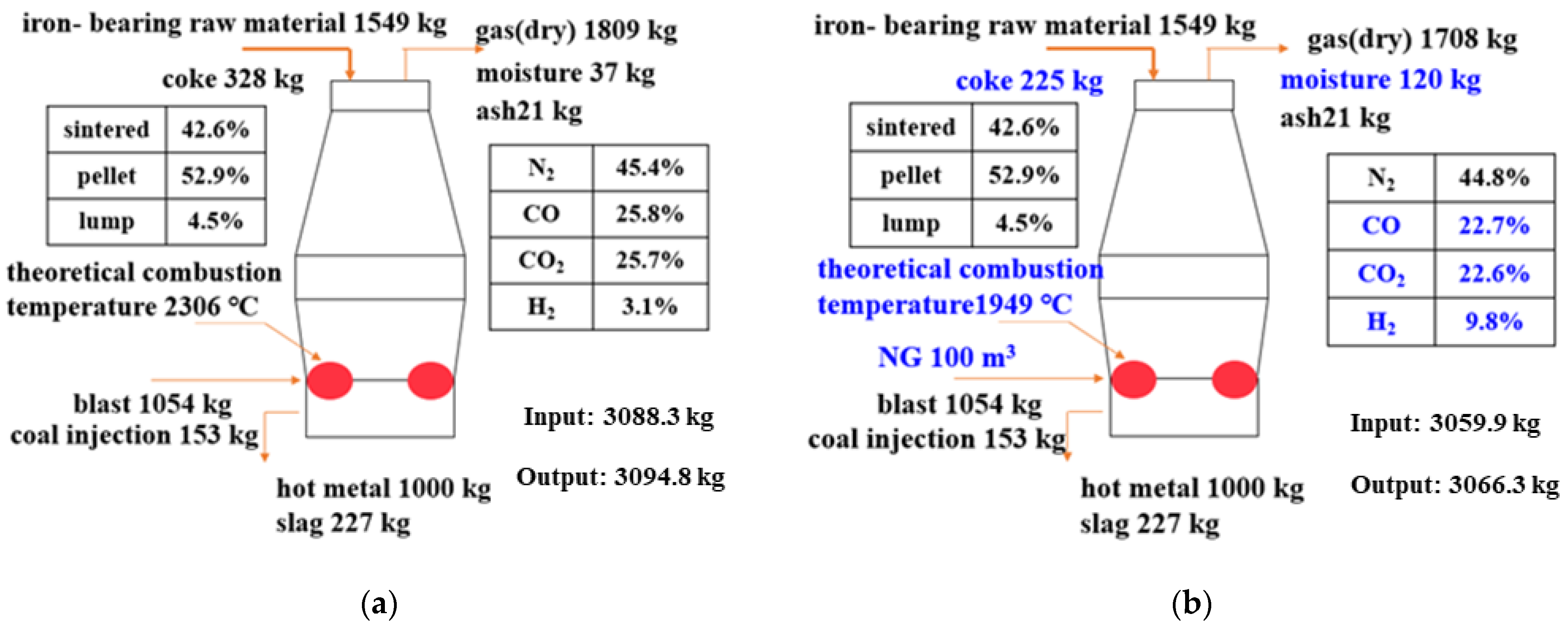
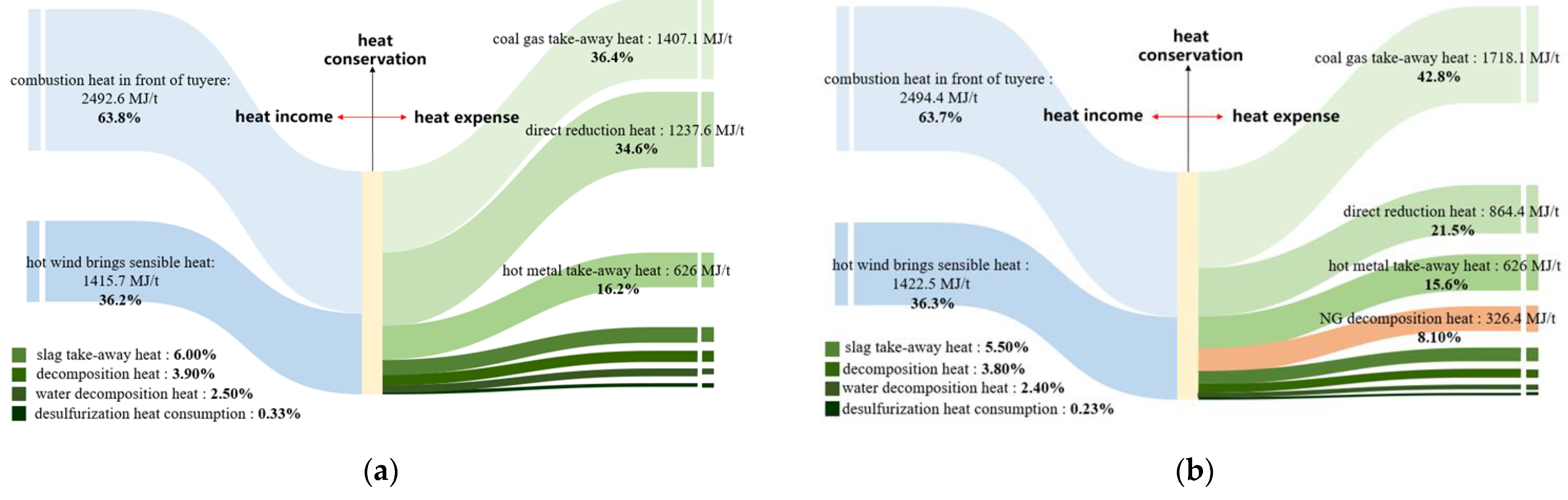
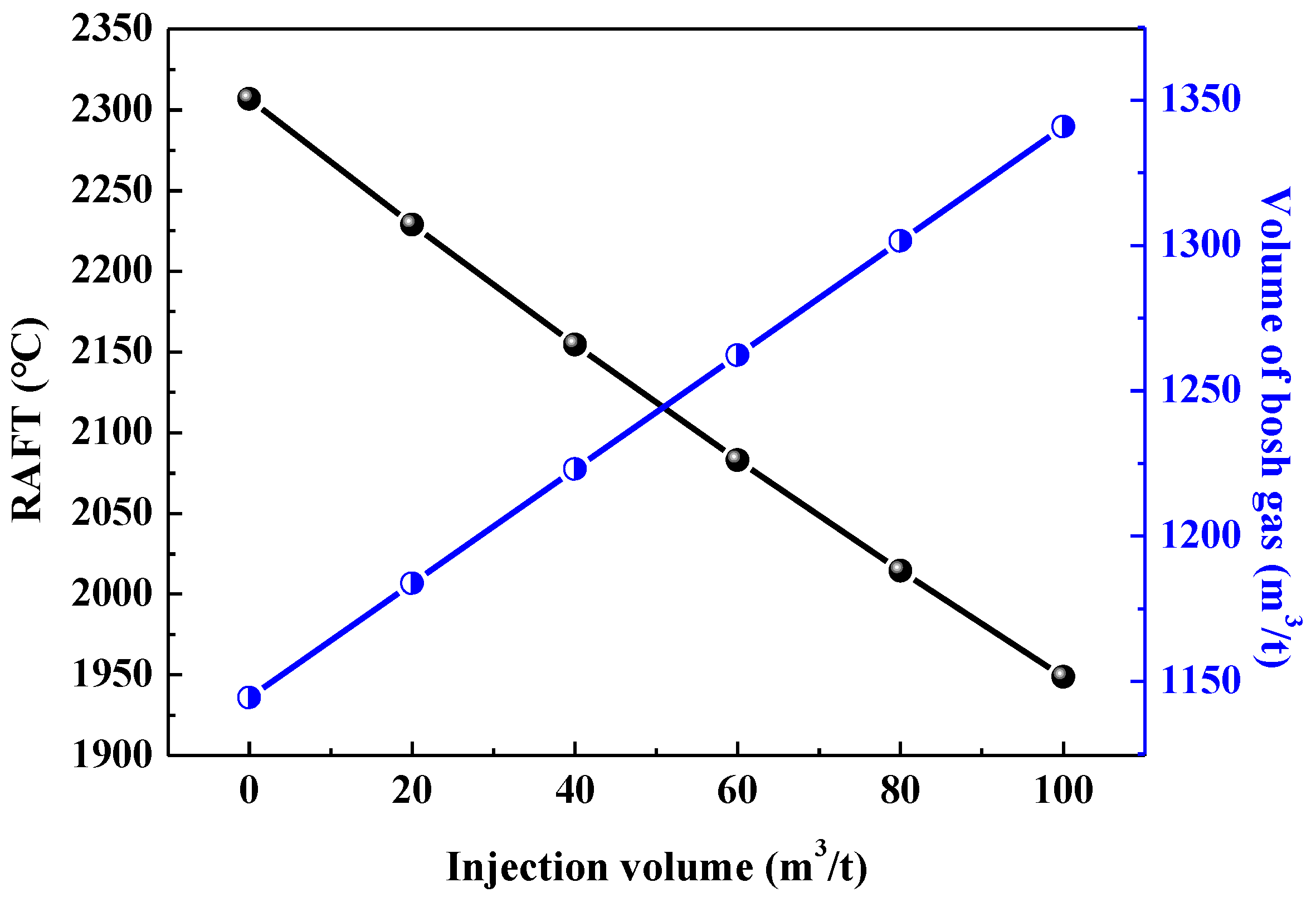
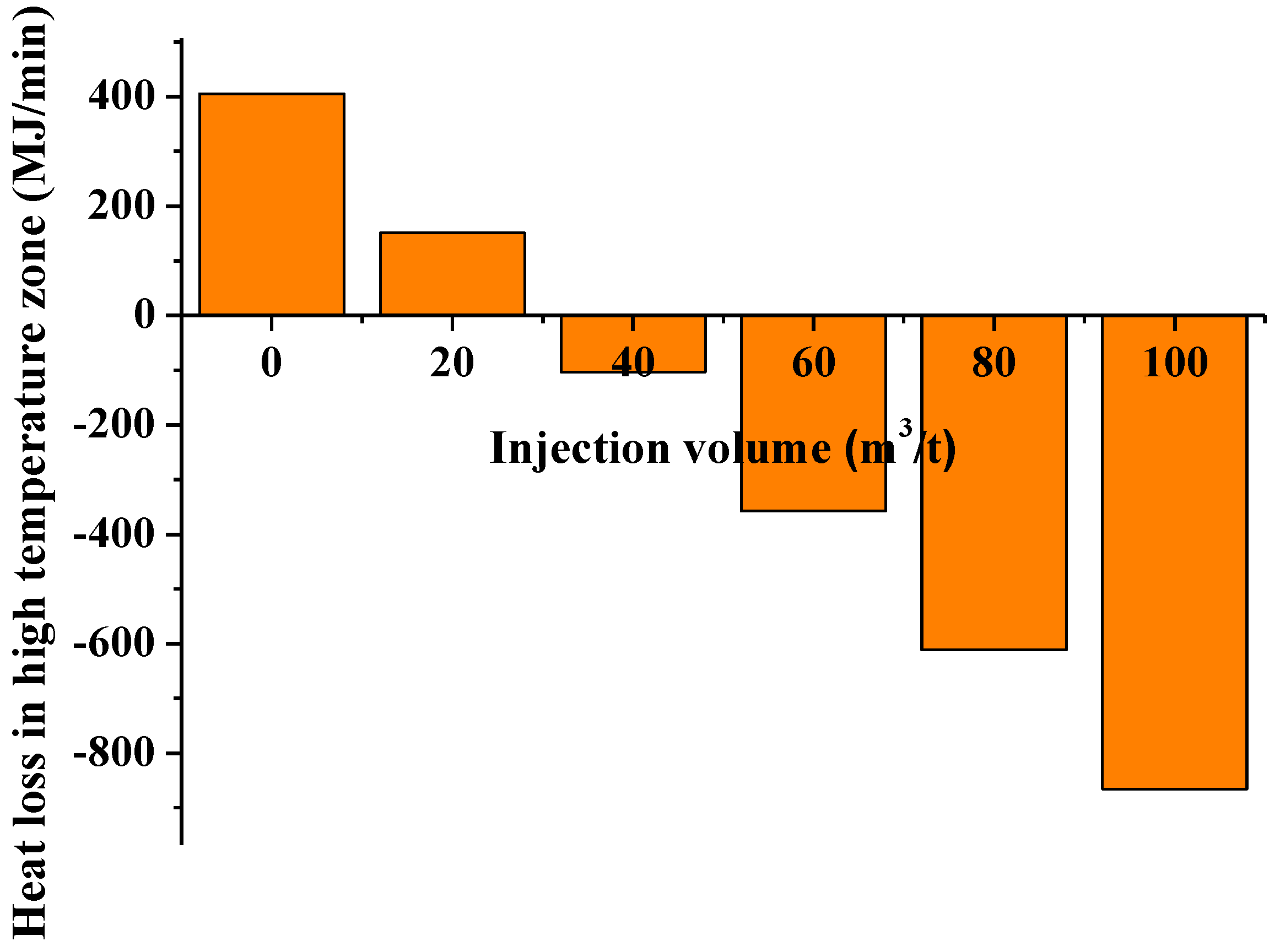
3.1. NG Injection with No Thermal Compensation

Under the condition that the raw fuel and operating parameters remain unchanged, the comparison between the base case and after injecting 100 m3/t NG was shown in Figure 1. Two main changes can be found in Figure 1, one is that the RAFT decreases and the other is the volume of H2 increases in furnace. For the characteristic of RAFT, under the constant oxygen volume in the tuyere zone, the heat released by the reaction between per unit oxygen with CH4 is less than that by combustion of C, as demonstrated in Equations (7) and (8). Furthermore, the volume of bosh gas increases in the case with NG injection. The above two reasons lead to the decrease of RAFT. For the volume of H2, it is expected that NG injection will increase H2 content and the reduction potential, which is conducive to promoting the indirect reduction, thus reducing the coke ratio and increasing the H2O content.
CH 4 g + 1 / 2 O 2 g = CO g + 2 H 2 g    H = - 35 . 4   kJ / mol
C s + 1 / 2 O 2 g = CO g    H =   - 110 . 5   kJ / mol
To specify the thermal state of the NG injection in the blast furnace, the heat balance of the whole furnace and high temperature zone (areas of direct reduction, combustion and slag iron melting occur in blast furnace) were analyzed. Table 4 shows the whole furnace heat balance with and without NG injection. As shown in Table 4, the heat in before and after the gas injection are essentially the same, 3908.3 MJ/t and 3916.9 MJ/t, respectively. For the heat out, in the case with 100 m3/t NG injection, the heat out associated with direct reduction of iron is reduced to 766.2 MJ/t compared with the base case of 1238 MJ/t. The main reasons are due to the increase of decomposition heat of NG, and the development of indirect reduction leading to lower heat consumption of direct reduction of Fe. Thus, for the heat loss (also called heat surplus in some literatures) in the base case is 215 MJ/t, while for the case with 100 m3/t NG injection, the heat loss increases to 365.9 MJ/t, indicating that the heat of the whole furnace is sufficient. However, considering the heat balance in the high temperature zone, as shown in Figure 2, the NG injection without thermal compensation will lead to insufficient heat in the high temperature zone.
It can be seen from Figure 2, the heat in of the high temperature zone with and without NG injection are similar, while the heat out changes greatly. Compared with the base case, the heat taken away by the reducing gas after NG injection increases from 1407.1 MJ/t to 1718.1 MJ/t, and the decomposition heat of NG in the high temperature zone also increases the heat expenditure. Although NG injection reduces the direct reduction degree and contributes to a reduction of 373.2 MJ/t in the heat of direct reduction in the high temperature zone, the overall heat loss in the high temperature zone under the base case is 45.4 MJ/t, whereas the heat loss under the gas injection condition is −96.9 MJ/t. This shows that, without thermal compensation measures, the injection of NG will lead to insufficient heat in the high temperature zone of blast furnace, which will easily lead to the hearth being too cold and the blast furnace being damaged. Therefore, in the operation of NG injection in a blast furnace, certain thermal compensation is required.
The influence of NG injection on the RAFT and the amount of bosh gas in the furnace without thermal compensation is shown in Figure 3. The RAFT of the base case is 2306 °C and the bosh gas volume is 1144 m3∙t−1. When no thermal compensation measures are taken, the RAFT gradually decrease while the bosh gas volume increase with the increase of the volume of NG. For every 10 m3·t−1increase in NG injection, the RAFT lowers by 35.8 °C and the volume of bosh gas rises by 19.6 m3∙t−1. Previous work has found that the RAFT decreased by 1.2–1.5 °C for 1 m3 coke oven gas (COG) injected into BF to replace coal [14]. Compared with COG, the RAFT of NG injection decreases by a higher margin, which puts forward higher requirements for thermal compensation measures of NG injection.
Figure 4 shows the effect of NG injection on the heat loss in the high temperature zone of the blast furnace without thermal compensation measures. With the increase of NG injecting volume, the heat loss in the high temperature zone of the blast furnace tends to be negative, and the heat out in the high temperature zone increases by 2.12 MW (127 MJ/min) for every 10 m3 of NG injection. Without thermal compensation measures, the limit gas injecting volume to keep the heat income in the high temperature zone higher than the heat out is 31.9 m3/t. If 80% of the heat loss in the high temperature zone relative to the base case is the lower limit of acceptable heat, the acceptable volume of NG can reach 6.4 m3/t. Therefore, in order to increase the amount of NG injection in Jingtang blast furnace, it is necessary to explore the impact of thermal compensation measures on NG injection.

3.2. NG Injection with Thermal Compensation

To maintain the smooth furnace condition and slag-iron fluidity of the blast furnace, it is necessary to ensure the heat in the high-temperature zone to avoid over-cooling of the furnace hearth and poor slag-iron separation. In this work, the heat loss in the high temperature zone was used as constraint. When the heat loss in the high temperature zone with NG injection is consistent with the base case (this condition is referred to as as Base-100 in the following) or reaches the 80% of base case (called Base-80 in the following), acceptable quantities of NG injection can be obtained. In the actual production process, reducing the coal ratio, increasing blast temperature, and increasing the oxygen enrichment rate can be used as thermal compensation measures.

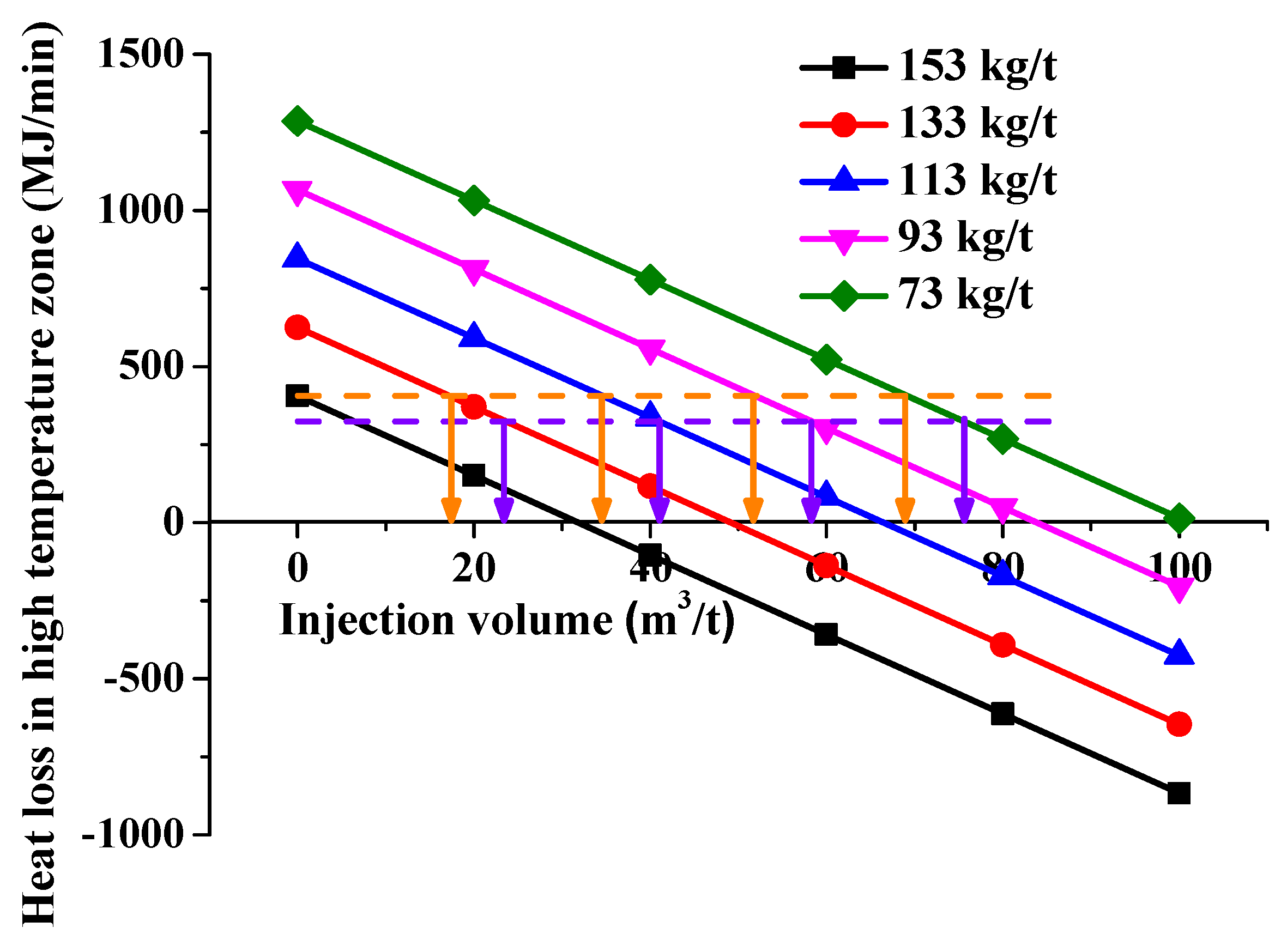
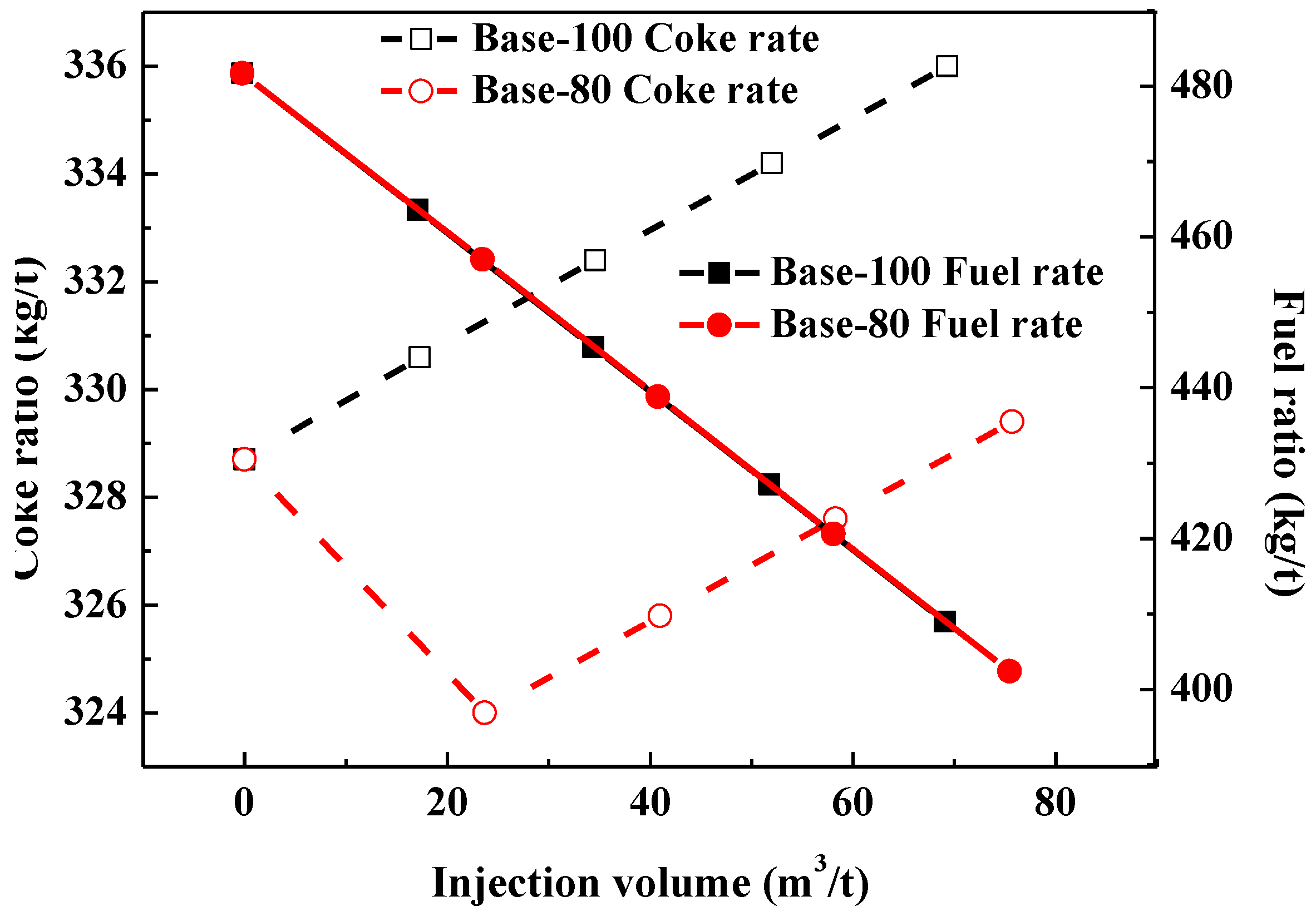
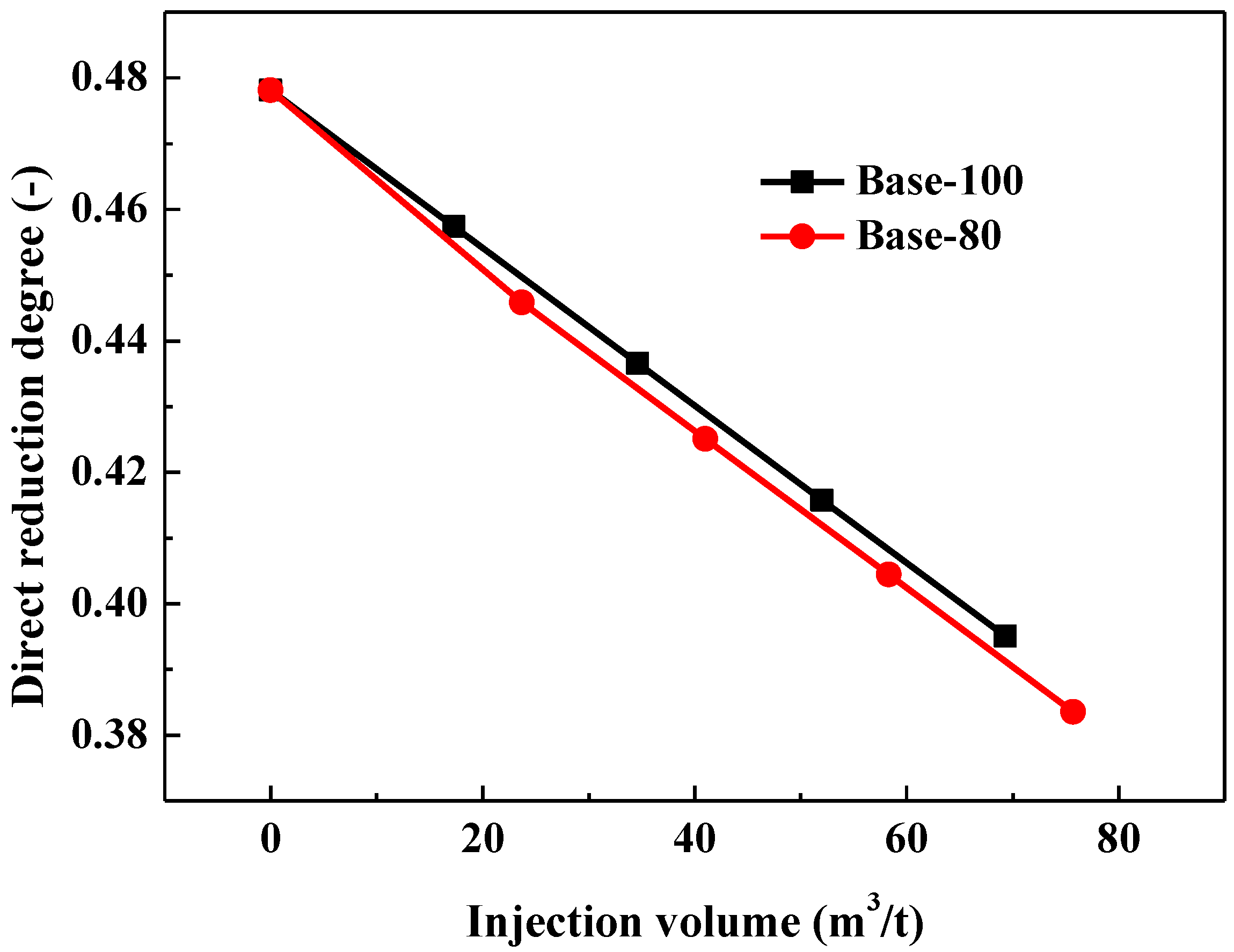
3.2.1. Reducing Coal Ratio

Figure 5 Effect of NG injection on heat loss in the high temperature zone of the blast furnace at different coal ratios. As can be seen from Figure 5, the heat loss in the high temperature zone gradually increases as the coal ratio decreases, indicating that the heat surplus in the high temperature zone increases. When the heat loss is consistent with the base case, the acceptable quantities of NG injection are 17.3, 34.6, 52, 69.3 m3/t (shown as the red inverted triangle symbols located on the x-axis) for every 20 kg/t of coal injection reduction. When the heat loss reaches 80% of the base case, the acceptable quantities of NG injection increase to 23.7, 41.0, 58.3, 75.7 m3/t (shown as the violet inverted triangle symbols located on the x-axis) for every 20 kg/t of coal injection reduction.
Figure 6 shows the RAFT at different suitable NG injection volumes under different coal ratios. It can be seen that the RAFT gradually decreases with the increase of injection volume for both Base-100 and Base-80. For Base-100, the RAFT decreases to 2277.4, 2256.9, 2234.4, and 2210.1 °C, respectively, relative to the base case 2306 °C for the suitable injection volumes of 17.3, 34.6, 52, and 69.3 m3/t, and the RAFT decreases even more for the Base-80 condition. It can be seen that the RAFTs are lower than that of base case, despite that the heat loss in the high temperature region with NG injection are the same as the base case.
Table 5 shows the variation of volume and composition of bosh gas under different acceptable quantities of NG. It can be seen under Base-100, with the increase of acceptable quantities of NG, the bosh gas volume increases from 1144.4 m3/t to 1167.1, 1189.7, 1212.4 and 1235.1 m3/t relative to the base case, with an increase of 2.0%, 4.0%, 5.9% and 7.9% respectively. For Base-80, the bosh gas volume increases more. Thus, in addition to ensuring sufficient heat in the high temperature zone, it is also necessary to pay attention to the increase of bosh gas volume with the increase of NG injection volume, which will lead to the increase of pressure drop in the blast furnace.
It can also be seen from Table 5, with the increase of the amount of NG injection, the CO concentration gradually decreases, while the H2 concentration gradually increases, and the total amount of reducing gas increases. The main reason is the increase in the amount of reducing gas brought in by the NG, especially the higher H2 content, which results in a lower concentration of CO. As the blast volume is kept constant, the total amount of N2 brought in by the air remains unchanged. Only the hydrogen enrichment effect of NG injection reduces the proportion of N2.
The direct reduction degrees of blast furnace under different suitable gas injection volumes are shown in Figure 7. Under Base-100, the direct reduction degree decreases by 0.021, 0.042, 0.062 and 0.083, respectively, relative to 0.478 under base case. The reduction of direct reduction degree under Base-80 is even greater. The reduction potential in the blast furnace can be strengthened by injecting natural gas. Thus, the indirect reduction can be improved, the direct reduction can be reduced, and the fuel consumption of the blast furnace can be reduced.
Figure 8 shows the coke ratio and fuel ratio of the blast furnace at different suitable gas injection volumes. It can be seen that, under Base-100, the coke ratio increases slightly relative to the base case. This is mainly because the reduction of pulverized coal injection at the tuyere is greater than the increase of natural gas, so that part of the oxygen in the combustion zone reacts directly with coke, which makes the overall coke ratio in the blast furnace slightly increase. For the overall fuel ratio, the saved fuel ratios are 18.1, 36.3, 54.7 and 72.7 kg/t respectively, and the overall replacement ratio is about 1.05 kg/m3. For Base-80, the coke ratio decreases first and then increases, and its overall fuel ratio gradually decreases.
Overall, the NG injection in a blast furnace without thermal compensation measures will face the problem of insufficient heat in the high temperature zone, showing the characteristics of “lower cooling and upper heating”. Reducing the coal ratio as a thermal compensation measure for NG injection, the operations are more convenient, the lower operation system is less changed, and the thermal compensation effect is easy to achieve. However, the outstanding disadvantage is that the proper injection of NG only depends on coal reduction, and the coke saving effect is average. The main reason is that natural gas replaces pulverized coal, and the economy is poor. It should be pointed out that NG injection can make full use of its hydrogen enrichment effect, reduce the CO2 emissions of blast furnaces, and in areas where the total coal consumption is limited, natural gas injection can solve the problem of insufficient coal indicators.

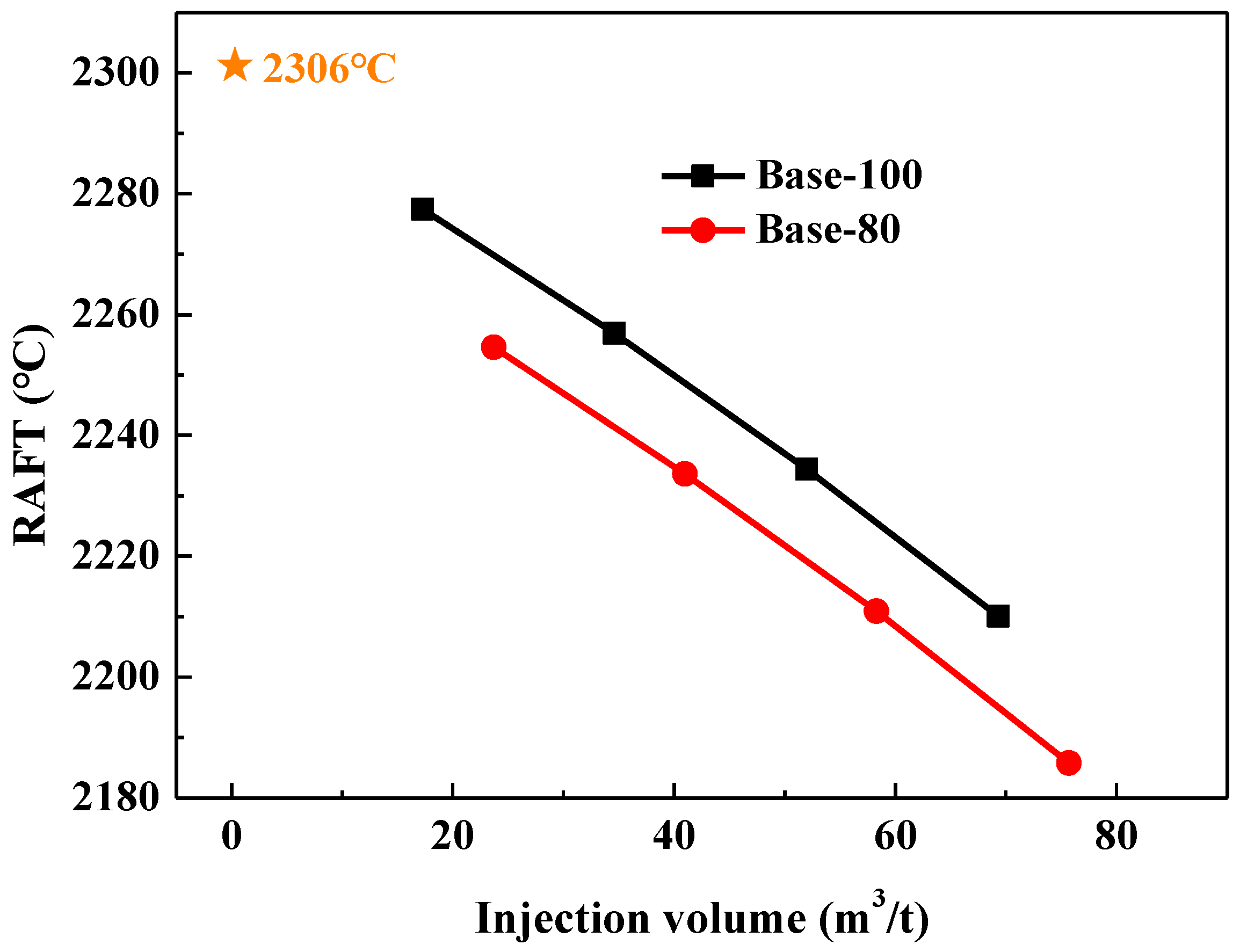
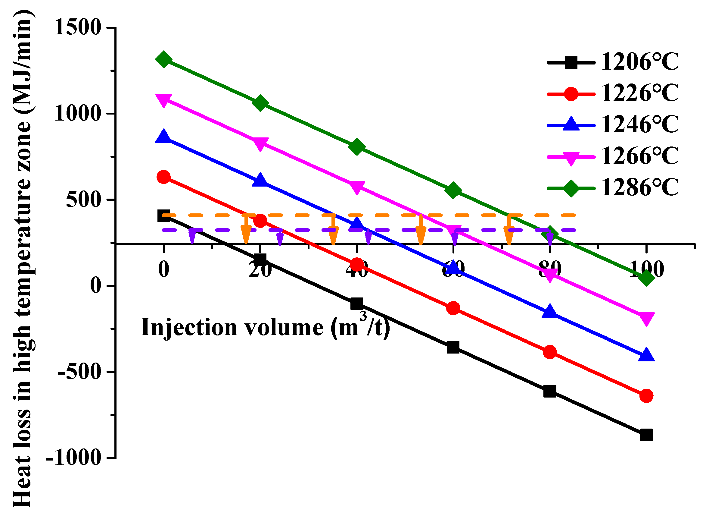
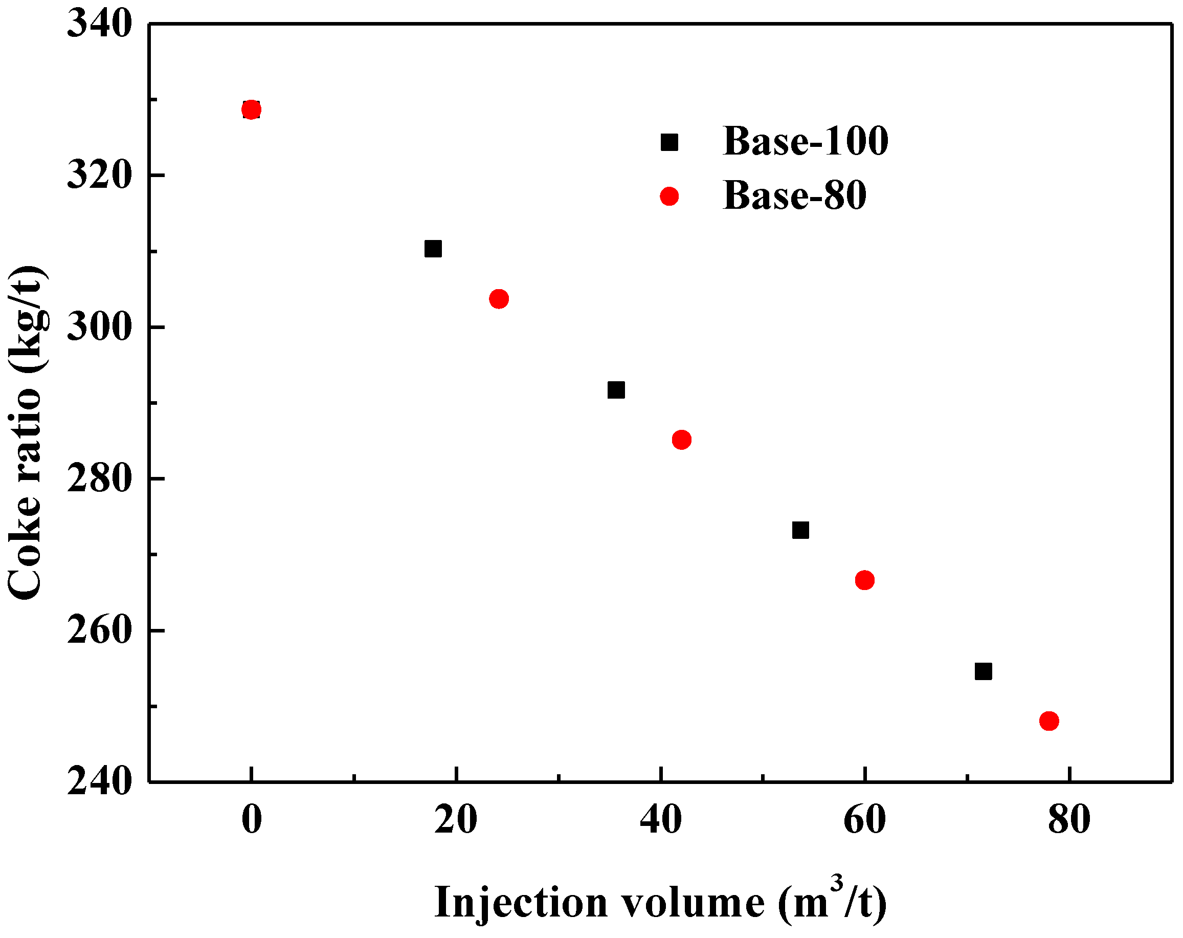
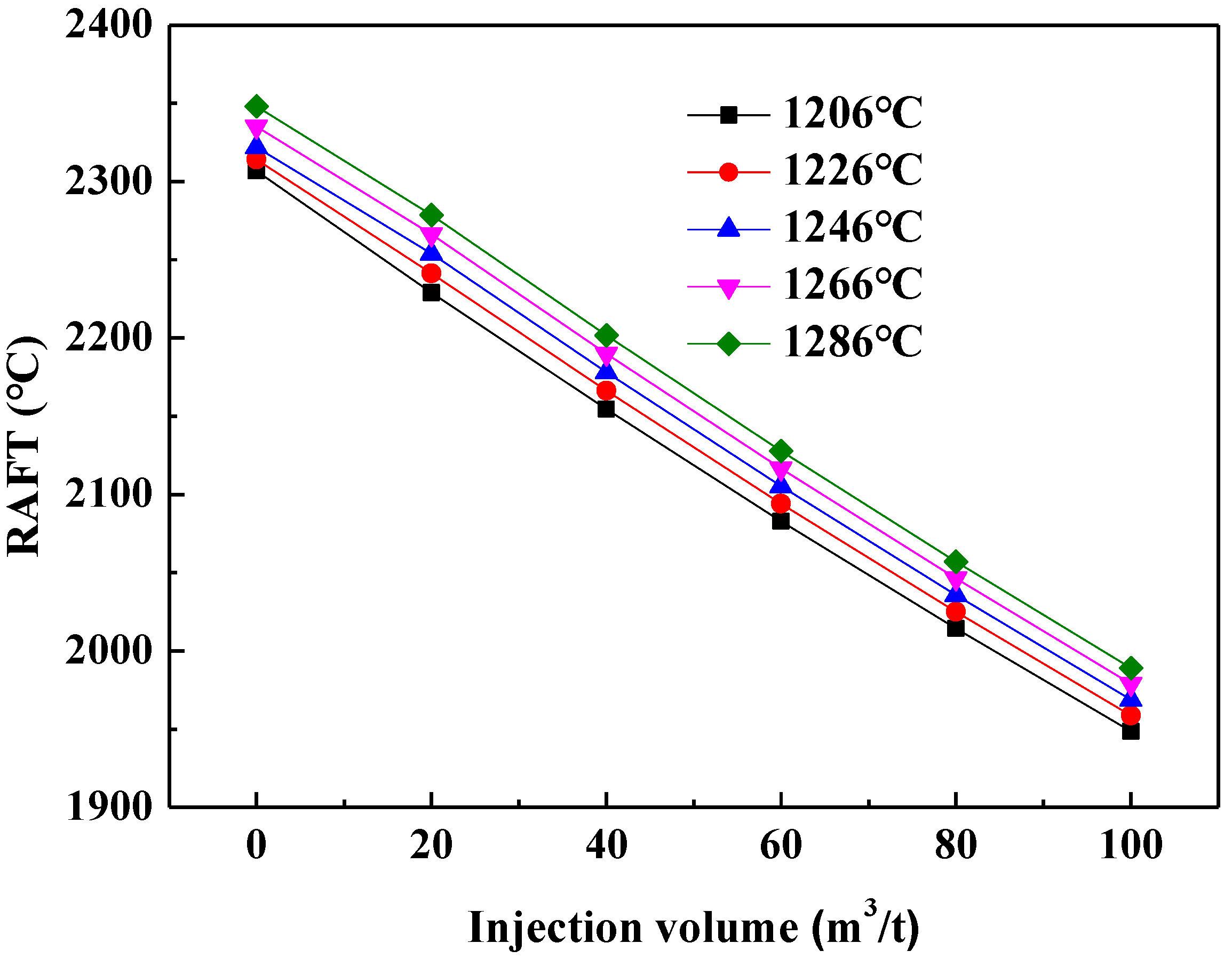
3.2.2. Increasing Blast Furnace Temperature

Figure 9 shows the effect of NG injection on the RAFT under different blast temperatures. As can be seen, due to the increase of air temperature, the direct physical heat brought by hot air increases, and the RAFT increases. Under the same injection amount, the theoretical combustion temperature increases by 5.9 °C for every 10 °C increase in the blast temperature. Under the same blast temperature, the RAFT drops by about 34 °C for every 10 m3/t of natural gas injection.
Figure 10 shows the heat loss in the high temperature zone of the blast furnace after injecting NG under different blast temperatures. It can be seen that, compared with the condition without thermal compensation measures, under the same NG injection volume, the heat loss in the high temperature zone increases by 3.8 MW (228 MJ/min) for every 20 °C increase in the blast temperature, indicating that the heat in the high temperature zone is more sufficient. At the same blast temperature, the heat loss in the high temperature zone will decrease by about 1.89 MW (113.5 MJ/min) for every 10 m3/t of natural gas injection. When 100% of the heat loss in the high temperature zone of the base case is taken as the standard, the acceptable quantities of NG are 17.8, 35.7, 53.7, 71.6 m3/t for each increase of 20 °C wind temperature. For Base-80, the acceptable quantities of NG are 24.2, 42.1, 60.0 and 78.0 m3/t for each 20 °C air temperature increase.
Table 6 shows the variation of the volume and composition of bosh gas under different acceptable quantities of NG. For Base-100, the NG injection volume will increase by about 17 m3/t when the blast temperature is increased by 20 °C, and the gas volume in the bosh will increase by about 35 m3/t. Under the same heat limit standard, the proportion of CO decreases by about 1% and the proportion of H2 increases by about 2.3% every time the blast temperature increases by 20 °C. At the same blast temperature, compared with Base-100, under the condition of Base-80, the proportion of CO decreases by 0.4% and the proportion of H2 increases by 0.8%.
Figure 11 shows the coke ratio of the blast furnace under different suitable gas injection volumes. With the increase of NG injection, the coke ratio decreases gradually. For Base-100, the coke ratio is 310.3, 291.7, 273.2 and 254.6 kg/t, respectively, under the appropriate natural gas injection amount. Compared with Base-100, the acceptable quantities of NG in Case-80 are higher and thus the coke ratios are lower. At the same blast temperature, the coke ratio in Base-80 is 6.6 kg/t less than that of Base-100.

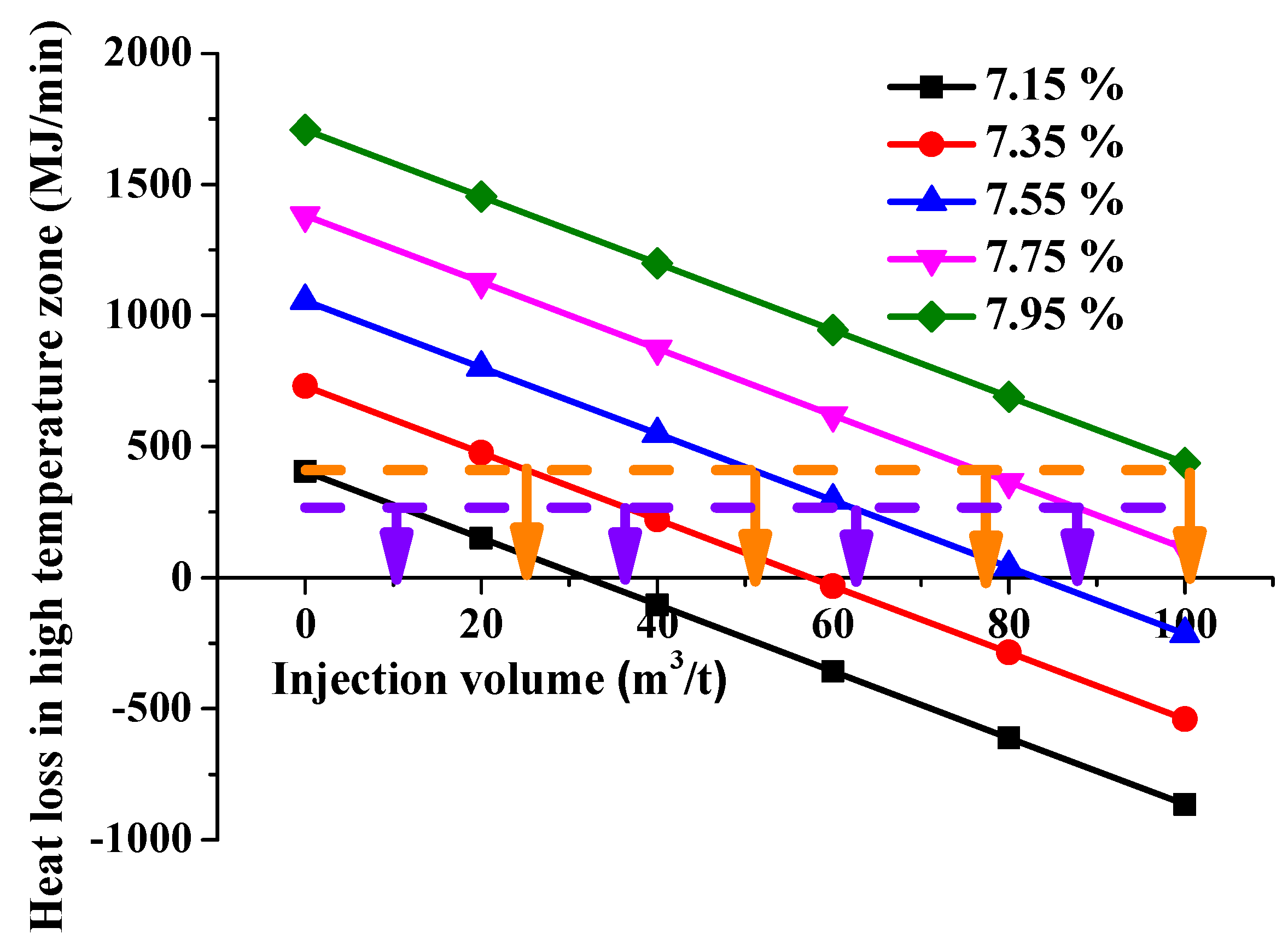
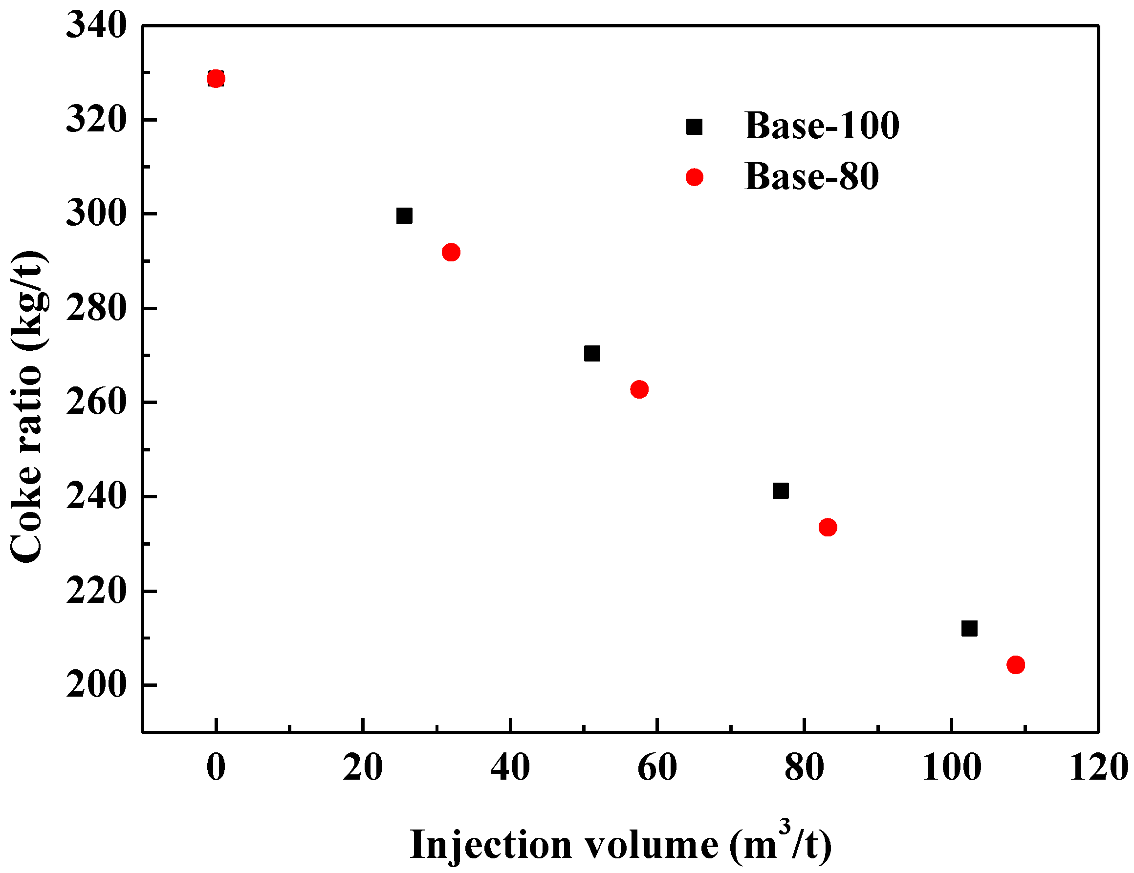
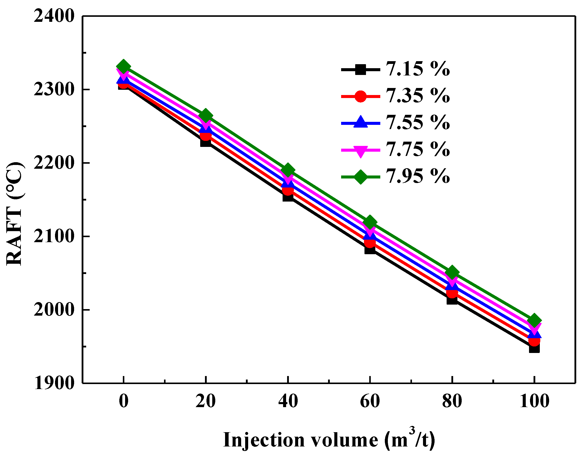
3.2.3. Increasing Oxygen Content

Figure 12 shows the effect of blast furnace injecting gas on the RAFT after raising the oxygen enrichment rate. The oxygen enrichment rate of 7.15% is used as the base, and each time it is raised by 0.2% until 7.95%. At the same NG injecting volume, each 1% increase in oxygen enrichment rate increases the RAFT by about 44.8 °C. When the oxygen enrichment rate was 7.95%, the RAFT was 2264.5 °C, 2190.3 °C, 2119.3 °C, 2051.0 °C and 1985.5 °C for each 20 m3/t NG injecting volume increase.
Figure 13 shows the variation of heat loss in the high temperature zone after injecting NG at different oxygen enrichment rates. With the increase of the oxygen enrichment rate, the heat loss in the high temperature zone increases. At the same injecting volume, the heat loss in the high temperature zone increases by 5.43 MW (325.5 MJ/min) for each 0.2% oxygen enrichment rate increase. At the same oxygen enrichment rate, the heat loss decreases by about 4.23 MW (254 MJ/min) for each 20 m3/t of NG injected. For Base-100, the appropriate injecting volume is 25.6, 51.2, 76.8, 102.5m3/t for each 0.2% increase in oxygen enrichment rate, while for Base-80, the appropriate injecting volume is 31.9, 57.6, 83.2, 108.8m3/t.
Table 7 shows the influence of acceptable quantities of NG on the volume and composition of bosh gas under different oxygen enrichment rates. Both for Base-100 and Base-80, for every 0.2% increase in oxygen enrichment rate, the amount of bosh gas increases by about 55m3/t, and the CO content in the bosh gas will decrease with the increase of oxygen enrichment rate, while the H2 content will increase. At the same oxygen enrichment rate, the CO content of Base-80 decreases by about 0.38% relative to Base-100, and the H2 content increases by about 0.9%.
Figure 14 shows the influence of acceptable quantities of NG on the coke ratio under different oxygen enrichment rates. With the increase of oxygen enrichment rate, the coke ratio decreases continuously. Under the acceptable quantities of NG, the coke ratio will decrease by about 29.2 kg/t when the oxygen enrichment rate is increased by 0.2%. For Base-80, the coke ratio of Base-80 will further decrease by about 6.8 kg/t compared with Base-100 under the same NG injection volume.

4. Conclusions

The characteristics of BF operation of NG were investigated by means of a static model. The effect of thermal compensation measures on the NG injection was studied. The following conclusions could be drawn:
1.
Under no thermal compensation measures, with the increase of NG injection, the RAFT gradually decreases, the volume of bosh gas gradually increases, and the heat loss in the blast furnace’s high temperature zone tends toward negative values. NG injection in blast furnace without thermal compensation measures, the heat loss of the whole furnace increases, which means that the heat surplus of the whole furnace is sufficient. However, the heat in the high-temperature zone of blast furnace is insufficient, showing a characteristic of “low cooling and upper heating”.
2.
Based on the standard of maintaining the heat loss in the high-temperature zone, the acceptable NG injecting volumes are 17.3, 34.6, 52, 69.3 m3/t after the coal ratio is reduced by 20, 40, 60, 80 kg/t relative to the base case. The coke ratio is slightly higher relative to the base case condition, with increases of 1.8, 3.7, 5.5, 7.3 kg/t. While the total fuel ratio is reduced and the fuel ratio savings are 18.1, 36.3, 54.7, and 72.7 kg/t, respectively.
3.
The acceptable NG injecting volumes are 17.8, 35.7, 53.7, and 71.6 m3/t after the blast temperature is increased by 20, 40, 60, and 80 °C, respectively. The coke ratio is reduced by 18.4, 37.0, 55.5, and 74.1 kg/t. The coke saving effect is better when the blast temperature is increased as the thermal compensation measure, but the increase of NG injection is easy to cause the increase of the bosh gas volume in the blast furnace.
4.
After increasing the oxygen enrichment rate by 0.2%, 0.4%, 0.6%, and 0.8%, the acceptable NG injecting volumes are 25.6, 51.2, 76.8, and 102.5m3/t. The coke ratio is decreased by 29, 58, 87.5, 116.7 kg/t. As a thermal adjustment measure, increasing the oxygen enrichment promotes pulverized coal combustion, enhances the reduction capacity of bosh gas, and has good coke saving impact. However, increasing the oxygen enrichment rate necessitates additional supplemental oxygen, and the increase of bosh gas volume caused by the further increase of natural gas injection volume is obvious. It is necessary to combine with other thermal compensation measures and use the method of air reduction and oxygen enrichment to supplement oxygen to alleviate the increase of bosh gas volume.

Author Contributions

Conceptualization, H.Z. and M.K.; methodology, H.Z. and J.W.; formal analysis, Y.S.; investigation, S.L.; data curation, P.J.; writing—original draft preparation, K.W.; writing—review and editing, H.Z. and M.K.; supervision, S.W. and J.Z. All authors have read and agreed to the published version of the manuscript.

Funding

This work was supported by the National Key R&D Program of China [Grant number: 2021YFC2902400, 2021YFC2902401], and the National Natural Science Foundation of China [Grant Number: 51904023, 51804027].

Conflicts of Interest

The authors declare no conflict of interest.

References

  1. Xu, K. Low Carbon economy and iron and steel industry. Iron Steel 2010, 45, 1–7. (In Chinese) [Google Scholar]
  2. Zhao, P.; Dong, P. Carbon emission cannot be ignored in future of Chinese steel industry. Iron Steel 2018, 53, 1–7. (In Chinese) [Google Scholar]
  3. Teng, F.; Guo, P.M.; Kong, L.T.; Wang, L. Potential analysis on carbon dioxide reduction with hydrogen in iron-making process. Sinter. Pelletizing 2022, 47, 18–23. (In Chinese) [Google Scholar]
  4. Xu, T. Preliminary analysis of natural gas injection into blast furnace. Angang Technol. 1986, 21, 13–17. (In Chinese) [Google Scholar]
  5. Abdel Halim, K.S.; Andronov, V.N.; Nasr, M.I. Blast furnace operation with natural gas injection and minimum theoretical flame temperature. Ironmak. Steelmak. 2009, 36, 12–18. [Google Scholar] [CrossRef]
  6. Babich, A.; Yaroshevskii, S.; Formoso, A.; Cores, A.; Garcia, L.; Nozdrachev, V. Co-injection of noncoking coal and NG in blast furnace. ISIJ Int. 1999, 39, 229–238. [Google Scholar] [CrossRef]
  7. Jampani, M.; Gibson, J.; Pistorius, C.P. Increased use of natural gas in blast furnace ironmaking: Mass and energy balance calculations. Metall. Mater. Trans. B 2019, 50, 1290–1299. [Google Scholar] [CrossRef]
  8. Guo, T.L.; Chu, M.S.; Liu, Z.G.; Zhao, K. Numerical Simulation of Blast Furnace Raceway under Natural Gas Injection. In Proceedings of the National Ironmaking Production Technology Conference and Ironmaking Academic Annual Conference Collection, Wuxi, China, 12–14 June 2012; pp. 23–28. (In Chinese). [Google Scholar]
  9. Wen, G. Discussion on natural gas injection into blast furnace. Ironmaking 1987, 6, 12–16. (In Chinese) [Google Scholar]
  10. Zhang, W.; Wang, Z.Y.; Zhang, L.G.; Wang, X.L. Experimental study on pulverized coal added dust injection into blast furnace. In Proceedings of the 9th China Steel Conference (CSM Biennial Conference), Beijing, China, 23 October 2013. (In Chinese). [Google Scholar]
  11. Qi, Y.H.; Yan, D.L.; Gao, J.J.; Zhang, J.C.; Li, M.K. Study on industrial test of the oxygen blast furnace. Iron Steel 2011, 46, 6–8. (In Chinese) [Google Scholar]
  12. Li, H.; Liu, K.; Sha, Y. Numerical simulation on heat equilibrium of BF COG injection. Iron Steel Vanadium Titan. 2011, 32, 1–5. (In Chinese) [Google Scholar]
  13. Andahazy, D.; Loffler, G.; Winter, F.; Burgler, T. Theoretical analysis on the injection of H2, CO, CH4 rich gases into the blast furnace. ISIJ Int. 2005, 45, 166–174. [Google Scholar] [CrossRef]
  14. Chen, Y.X.; Wang, G.W.; Zhang, J.L.; Su, B.X.; Zuo, H.B. Theoretical analysis of injection coke oven gas with oxygen enriched into blast furnace. Iron Steel 2012, 47, 12–16. (In Chinese) [Google Scholar]
  15. Dong, Z.S.; Xue, Q.G.; Zuo, H.B.; She, X.F.; Wang, G. Mathematical model analysis on coke oven gas injection into oxygen blast furnace. Iron Steel 2017, 52, 18–24. (In Chinese) [Google Scholar]
  16. Cheng, X.F.; Zhang, F.M.; Qing, G.L.; Xu, M.; Zhang, Y. Research on main technical parameters of blast furnace with natural gas injection. J. Iron Steel Res. 2022, 34, 944–951. (In Chinese) [Google Scholar]
  17. Castro, J.A.; Nogami, H.; Yagi, J. Numerical Investigation of Simultaneous Injection of Pulverized Coal and Natural Gas with Oxygen Enrichment to the Blast Furnace. ISIJ Int. 2002, 42, 1203–1211. [Google Scholar] [CrossRef]
  18. Guo, T.L.; Chu, M.S.; Liu, Z.G.; Tang, J.; Yagi, J. Mathematical modeling and exergy analysis of blast furnace operation with NG injection. Steel Res. Int. 2013, 84, 333–343. [Google Scholar] [CrossRef]
  19. Zhang, C. Blast furnace hydrogen-rich metallurgy-research on efficiency injection of natural gas and pulverized coal. Fuel 2022, 311, 122412. [Google Scholar] [CrossRef]
Figure 1. Comparison of mass flow for base case (a), and injection of 100 m3/t NG without thermal compensation (b).
Metals 12 02107 g001
Figure 2. Heat balance in the high temperature zone for base case (a) and injection of 100 m3/t NG conditions without thermal compensation (b).
Metals 12 02107 g002
Figure 3. Effect of NG injection on the RAFT and volume of bosh gas.
Metals 12 02107 g003
Figure 4. Effect of NG injection on heat loss in the high temperature zone.
Metals 12 02107 g004
Figure 5. Effect of NG injection on heat loss in the high temperature zone of blast furnace under different coal ratios.
Metals 12 02107 g005
Figure 6. RAFT under different acceptable quantities of NG.
Metals 12 02107 g006
Figure 7. Direct reduction degrees of blast furnace under different suitable gas injection volumes.
Metals 12 02107 g007
Figure 8. Coke ratio and fuel ratio of the blast furnace under different suitable gas injection volumes.
Metals 12 02107 g008
Figure 9. Effect of NG injection on RAFT under different blast temperatures.
Metals 12 02107 g009
Figure 10. Effect of NG injection on heat loss in the high temperature zone of blast furnace under different blast temperatures.
Metals 12 02107 g010
Figure 11. Coke ratio of blast furnace under different suitable gas injection volumes.
Metals 12 02107 g011
Figure 12. Effect of NG injection on RAFT under different oxygen enrichment rates.
Metals 12 02107 g012
Figure 13. Effect of NG injection on heat loss in the high temperature zone of blast furnace under different oxygen enrichment rates.
Metals 12 02107 g013
Figure 14. Effect of acceptable quantities of NG on the coke ratio under different oxygen enrichment rates.
Metals 12 02107 g014
Table 1. Raw material composition (mass fraction)%.
Raw MaterialProportion, %TFeFeOCaOSiO2MgOAl2O3S
Sinter42.656.348.510.915.42.041.810.02
Pellet52.965.780.511.882.580.790.570.024
Lump ore4.564.690.310.093.330.0191.210.02
Table 2. Fuel composition (mass fraction)%.
Coke
C86.52
VolatileCOCO2CH4H2N2
1.240.420.440.060.110.21
AshSiO2CaOMgOAl2O3P2O5Fes
12.006.240.380.0673.690.110.25
Pulverized coal
C72.88
VolatileCHON
17.997.724.235.031.02
AshSiO2CaOAl2O3FeS
8.803.880.433.420.10
Table 3. Chemical composition of NG%.
CompositionCH4CO2N2O2
Proportion, %97.062.080.790.07
Table 4. Heat balance of whole furnace for base case and the case with 100 m3/t NG injection under no thermal compensation.
Base Case
Heat inMJ/t%Heat outMJ/t%
Combustion in raceway2492.663.8Iron direct reduction123833.5
Inlet by tuyere1415.736.2Microelement reduction98.22.7
---Hot metal127634.6
---Slag432.411.7
---Top gas381.910.3
---Furnace dust3.10.09
---Carbonate decomposition00
---Water evaporation2.20.06
---Desulphurization12.90.35
---Coal powder desorption heat151.24.1
---Water decomposition97.82.6
Total income3908.3100Total expense3693.3100
Injection of 100 m3/t NG condition without thermal compensation
Heat inMJ/t%Heat outMJ/t%
Combustion in raceway2494.463.7Iron direct reduction766.221.6
Inlet by tuyere1422.536.3Microelement reduction98.22.8
---Hot metal127635.9
---Slag410.711.6
---Top gas410.411.6
---Carbonate decomposition00
---Water evaporation1.50.04
---Desulphurization9.30.26
---Coal powder desorption heat151.24.3
---NG decomposition326.49.2
---Water decomposition97.82.8
Total income3916.9100Total expense3551100
Table 5. Volume and composition of bosh gas under different acceptable quantities of NG.
ConditionsCoal Ratio
(kg/t)
Gas Injection Mass
(m3/t)
Bosh Gas Volume
(m3/t)
CO (%)H2 (%)CO + H2 (%)
Base case15301144.441.57.549
Base-10013317.31167.140.49.650.0
11334.61189.739.611.250.8
9352.01212.438.812.851.6
7369.31235.138.014.652.5
Base-8013323.71179.640.110.450.5
11341.01202.239.311.951.2
9358.31225.038.413.451.9
7375.71247.637.614.952.5
Table 6. Influence of acceptable quantities of NG on the volume and composition of bosh gas under different blast temperatures.
ConditionsBlast Temperature (°C)Injection Volume (m3/t)Gas Volume in the Belly of the Furnace (m3/t)CO (%)H2 (%)
Base case120601144.441.57.5
Base-100122617.81179.440.210.4
124635.71214.639.112.7
126653.71249.838.115
128671.61285.13717.3
Base-80122624.21191.939.811.2
124642.11227.138.713.5
1266601262.337.715.8
1286781297.636.618.1
Table 7. Influence of acceptable quantities of NG on the volume and composition of bosh gas under different oxygen enrichment rates.
ConditionsOxygen Enrichment Rate
(%)
Injection Volume
(m3/t)
Gas Volume in the Belly of the Furnace
(m3/t)
CO (%)H2 (%)
Base case7.1501144.441.57.5
Base-1007.3525.61199.339.9411.3
7.5551.21254.238.6614.6
7.7576.81309.137.3717.8
7.95102.5136436.0820.98
Base-807.35321211.839.5712.2
7.5557.61266.738.2915.38
7.7583.21321.63718.6
7.95108.81376.635.721.8
Publisher’s Note: MDPI stays neutral with regard to jurisdictional claims in published maps and institutional affiliations.

