Article

Study of Tensile Strength of Aluminum Alloy Caused by Pulsed Laser Drilling

1
State Key Laboratory of Laser Propulsion & Application, Space Engineering University, Beijing 101416, China
2
Technical Institute of Physics and Chemistry, Chinese Academy of Sciences, Beijing 100190, China
*
Authors to whom correspondence should be addressed.
Metals 2022, 12(12), 2049; https://doi.org/10.3390/met12122049
Submission received: 31 October 2022 / Revised: 25 November 2022 / Accepted: 26 November 2022 / Published: 29 November 2022
(This article belongs to the Special Issue Progress in Laser Advanced Manufacturing)

Abstract

:
In the process of pulsed laser drilling, the material properties in the heat-affected zone will change due to the thermal effect of the laser. To study the effect of this change on the material tensile strength, two lasers were used to punch the standard 6061 aluminum alloy specimens with millisecond and nanosecond pulse widths, and then the tensile test was carried out on the standard specimens with a tensile tester to measure the ultimate tensile strength of the aluminum alloy. Finally, the micro-morphology of the fracture was photographed by scanning electron microscopy (SEM), and the fracture mechanism of the aluminum alloy was analyzed. The experimental results show that the relationship between the rate of intensity change induced by the millisecond laser and the ablation area ratio is more linear than that of the nanosecond laser; with the increase of ablation area ratio, the rate of intensity changes induced by the nanosecond and millisecond lasers becomes increasingly closer; three types of fractures are produced with two types of laser ablation; the plasticity of the material rapidly decreases with laser drilling, and the main reason for decrease in plasticity was stress concentration. This study provides an important point of reference for how to ensure the strength and plasticity of the components after laser drilling.

1. Introduction

In recent years, the importance of laser drilling has become increasingly prominent, and it has unique advantages and irreplaceable roles in the high-quality hole processing of special materials [1]. Examples of their aerospace applications include drilling small holes in engine blades for cooling, drilling micro-holes in wing skins to reduce turbulence, and so on [2,3]. For laser processing with less demanding accuracy and the pursuit of efficiency, nanosecond laser and millisecond laser drilling have obvious advantages compared with ultrashort pulse-laser drilling [4]. Due to different pulse widths, there are differences in material removal, heat-affected zone, and hole quality during nanosecond and millisecond-laser drilling processes [5]. For nanosecond lasers, vaporization occurs at the moment of interaction with the material, and a small amount of molten material is generated. The target vapor continues to absorb the laser to generate plasma and drives the molten material jet, resulting in material removal [6]. For the millisecond laser, the main reasons for material removal are the vaporization of the material and the injection of molten material [7]. Due to the low power density of the millisecond laser, a large amount of molten material is discharged from the small hole without vaporizing, thus the material removal efficiency of the millisecond laser is higher [8]. However, at the same time, more recast layers will be produced. In some cases, the recast layers are accompanied by micro-cracks during the process, which will seriously affect the quality of holes [9]. In addition to the material removal, the difference between the effects of nanosecond and millisecond lasers on materials is also reflected in the mechanical effects. The process of nanosecond laser-induced plasma generation induces shock waves on the surface, and the material is plastically deformed by the high-intensity pressure pulse, which generates compressive stresses inside the material [10,11]. During millisecond laser ablation of the material, the recoil of the vaporized material is not sufficient to deform the material plastically, but thermal stresses are also generated due to the different rates of temperature change during the solidification of the surface molten metal [12,13]. Researchers have conducted an exhaustive study of the parameters associated with laser drilling. Tunna et al. [14] investigated the effect of laser wavelength on the single-pulse ablation depth of aluminum alloys. They found that aluminum alloys have lower reflectivity for shorter wavelength lasers; thus, the ablation depth is deeper when using shorter wavelength laser ablation. Mishra and Yadava et al. [15] found that at a pulse width of 1 ms and a repetition frequency of 10 Hz, the amount of material removed per pulse increased with increasing hole depth. M. Schneider et al. [16] used the direct observation of drilled hole (DODO) method to accurately measure the ablation depth. Mishra et al. [17] investigated the effects of laser power density, pulse width, frequency, and material thickness on laser drilling and found that peak power density has a large effect on the heat affected zone, and significantly affects the material removal rate.
Most researchers have focused on the influence of laser input parameters on the geometric parameters of small holes. However, studies on the reduction of material cross-sectional area and thermal and mechanical effects of laser on the change of material strength and plasticity after laser drilling are very rare. In this paper, we focus on the strength change of the material after millisecond and nanosecond laser punching, and analyze the causes of the material strength change. This study is important for the parameter optimization of nanosecond and millisecond laser drilling, and further application of laser punching.

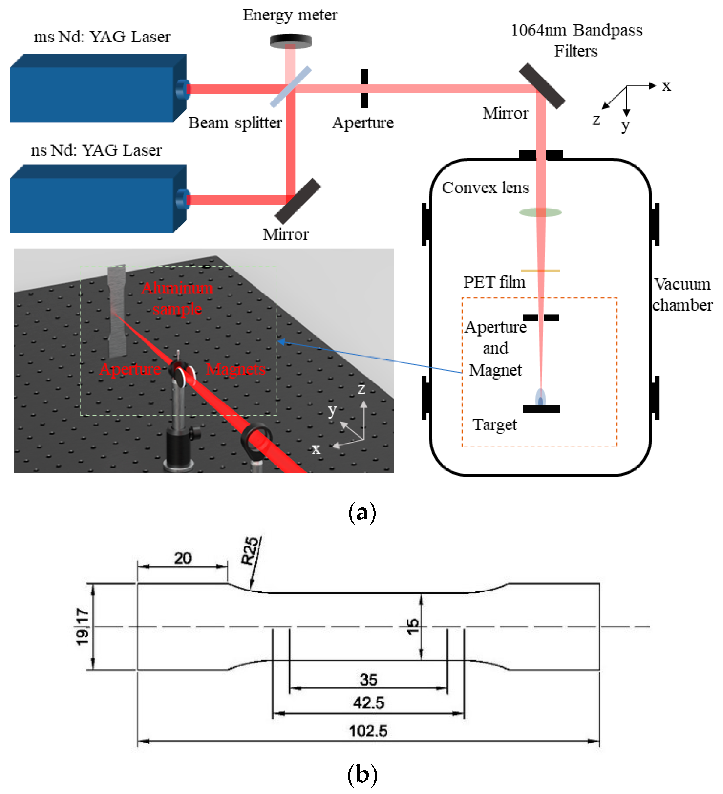
2. Materials and Methods

The schematic diagram of the experimental setup used for laser drilling is shown in Figure 1a. Laser parameters are shown in Table 1. The first laser source was a Nd:YAG laser with a wavelength of 1064 nm, and its full width half maximum (FWHM) is 0.5 ms, which produced a flat-topped laser beam with a beam divergence angle of less than 0.3 mrad. The energy distribution of the laser is not uniform at the edge part, thus the laser is cut down at the edge using the diaphragm, imparting a laser diameter of 14 mm and uniformly distributing the intensity. The second laser source was also a Nd:YAG laser with a wavelength of 1064 nm, and operated at a pulse width of 10 ns (FWHM). The beam produced by the laser was a Gaussian beam with a divergence angle of less than 0.3 mrad. Furthermore, an aperture was used to intercept the laser at the edge to endure that the beam diameter was 12 mm. The laser passed through a high-reflectivity mirror and entered a beam splitter, which reflected 10% of the energy into the energy meter and focused the other 90% on the sample surface through a focusing lens with a focal length of 300 mm. In the experiment, the maximum pulse energy of the second laser source was 660 mJ. After being focused by the lens, the peak power density of the laser exceeded the breakdown threshold of air. Due to the inverse tough absorption effect of the laser, the laser energy reaching the surface of the target was less than 660 mJ. In order to avoid this situation, the experiment was conducted in a vacuum environment with an ambient pressure of 5 × 10⁻³ Pa.
In the vacuum environment, to prevent the high-temperature plasma from heating the lens, thus causing drift of the lens focal point and damage to the lens coating, a diaphragm was installed 100 mm in front of the ablation point during the experiment, and the hole of the diaphragm was adjusted to be slightly larger than the beam diameter. A permanent magnet was placed 10 mm below the diaphragm. The magnetic field generated by the permanent magnet deflected most of the plasma’s trajectory, thus ensuring that the lens was not damaged during the ablation process.
The aluminum alloy (6061-T6) was clamped 320 mm from the lens, in order that it was in the defocusing state, in which the outer contour size of the ablation hole of the nanosecond laser and millisecond laser was almost the same. The target was designed in accordance with the standard GB/T228.1-2010 for the specimen size, and its parameters are shown in the Figure 1b.
The laser was used to drill 1–15 holes on the surface of 15 specimens in sequence. Due to errors, there may be a small deviation in some of the hole positions. As long as there is a certain distance between the hole positions and the material edges, influence of distance on results can be ignored. The pulse energy of the millisecond laser was 8.8 J, and three pulses were used for drilling each hole; the pulse energy of the nanosecond laser was 660 mJ, with a repetition frequency of 10 Hz, and 200 pulses were used for ablation of each hole. After measurement, the cross-sectional area of the hole in the aluminum alloy ablated by the millisecond laser was 1.42 mm2; and the cross-sectional area of the hole in the aluminum alloy ablated by the nanosecond laser was 1.73 mm2.
After punching the specimen, photos of all specimens were obtained and marked well. The specimens were fixed vertically on the jig of the testing machine. After mounting the sample, the tensile program of the testing machine was started and the tensile speed was set to 1 mm/min. The test automatically recorded the relevant data of stress and strain and stretched the sample until it broke. After the specimens were removed, the length-change data of the specimens were measured using a micrometer with an accuracy of 10 µm. All steps were repeated three times and the measurements were averaged. Finally, the morphology of the fracture was photographed by FEI Quanta FEG250 (FEI, Hillsboro, OR, the United States) field emission scanning electron microscope.

3. Results and Discussion

3.1. Yield Strength

Because there are variations in the strength of different batches of materials due to processing and other problems, the strength was normalized by randomly taking three specimens from the same batch for tensile experiments, testing the tensile strength, and taking the average value, to find the rate of strength change for different numbers of holes. The formula for calculating the rate of strength change is as follows:
k σ = σ b σ a σ a × 100 %
where, k σ is the rate of change of strength, σ b is the ultimate tensile strength of the original specimen, and σ a is the ultimate tensile strength of the specimen after drilling.
To facilitate the study of the effect of ablation holes on strength, we define the cross-sectional area of the ablation holes as the ablation area, and normalizing the ablation area to obtain the ablation area ratio. The ablation area ratio is calculated as follows:
k s = S b S a × 100 %
where, k s is the ablation area ratio, S b is the sum of the ablation hole cross-sectional area, and S a is the cross-sectional area in the height direction of the specimen.
The variation of the rate of strength change with the ablation area ratio for nanosecond and millisecond laser ablation of aluminum alloys is shown in Figure 2. It can be seen from Figure 2 that after the millisecond laser drilling of the material, the strength change rate of the material gradually decreased as the ablation area ratio increased with an approximately linear trend. After linear fitting by the least squares method, the slope is about −1.17. After nanosecond laser drilling of the material, the strength change rate of the material decreased with the increase of the ablated area ratio, but the trend is nonlinear. When the ablation area ratio was less than the critical value (ks~50–60%), the strength-change rate was also linear with the reduction of the ablation area ratio. After linear fitting by the least squares method, the slope is about −0.29. When the ablation area ratio is greater than the critical value, the strength of the material decreased rapidly. During laser ablation, two forms of residual stress are generated: one is that higher power causes material evaporation and the formation of plasma, which generates a stress wave that propagates into the material causing compressive residual stress [18]; and the other is that thermal residual stresses are generated in the heat affected zone due to differences in cooling rates and shrinkage rates between the surface and the inner region. For nanosecond-laser drilling, both residual stresses exist, whereas for millisecond lasers, thermal residual stress is the dominant residual stress around the hole. In general, the residual stress is compressive stress, which will improve the tensile strength of the material. Therefore, it can be seen from the curve trend in Figure 2 that the residual stress after nanosecond-laser drilling was significantly higher than that after millisecond laser drilling.

3.2. Elongation

Percentage elongation after fracture is the ratio of elongation after pulling the pitch to the original pitch, which is an important indicator of plastic deformation. Since percentage elongation after fracture of the material becomes very small after laser ablation, measuring the percentage elongation after fracture using the elongation of the pitch may introduce new errors; therefore, the elongation after pulling divided by the original length was used here as the elongation to reflect the material plasticity index. It can be calculated as follows:
δ = L a L b L b × 100 %
where, δ is the post-break elongation, L a is the total length of the specimen after fracture, and L b is the length of the original specimen.
The change curve of elongation with ablation area ratio after millisecond and nanosecond laser ablation of aluminum alloy is shown in Figure 3. When there was no ablation on the surface of the aluminum alloy specimen, the elongation reached 7 mm; when a hole was punched by the laser, the elongation quickly dropped to less than 2.5 mm. With the increase of the number of holes, the elongation continued to decrease and gradually tended toward zero. For the aluminum alloy specimens, the deformation not recovered after pulling is plastic deformation. Laser drilling made the plasticity of aluminum alloy decrease rapidly, and the plastic deformation of aluminum alloy gradually tended towards zero with the increase of ablation area ratio.
When the ablation area ratio of the material was less than 50%, the elongation after nanosecond laser drilling was slightly larger than that after millisecond laser drilling, and the plastic deformation was larger.

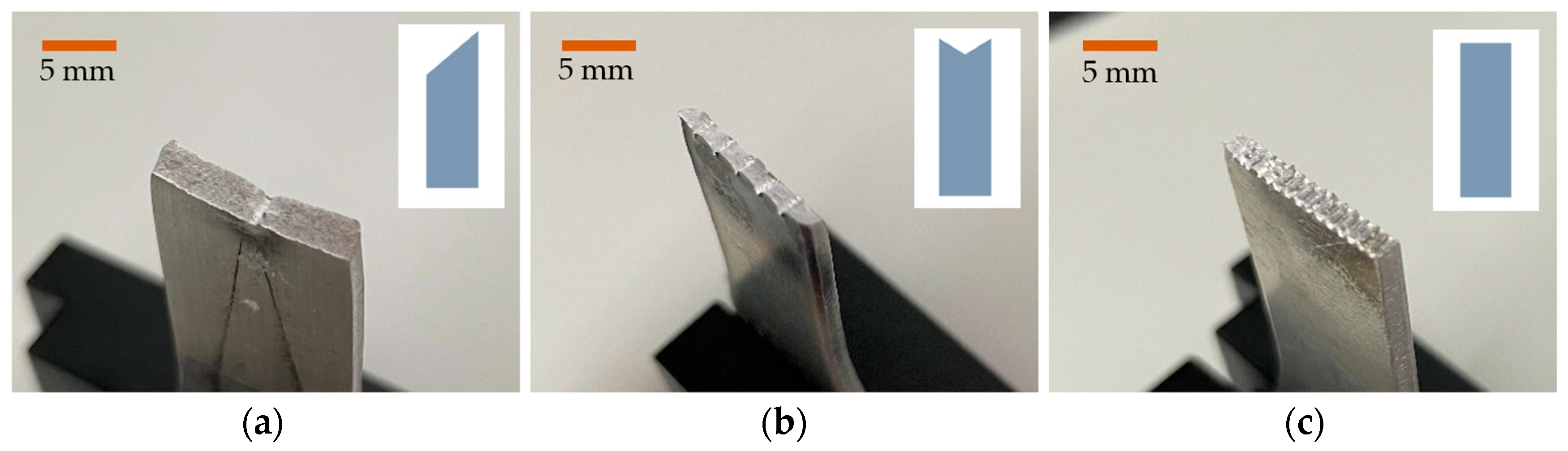
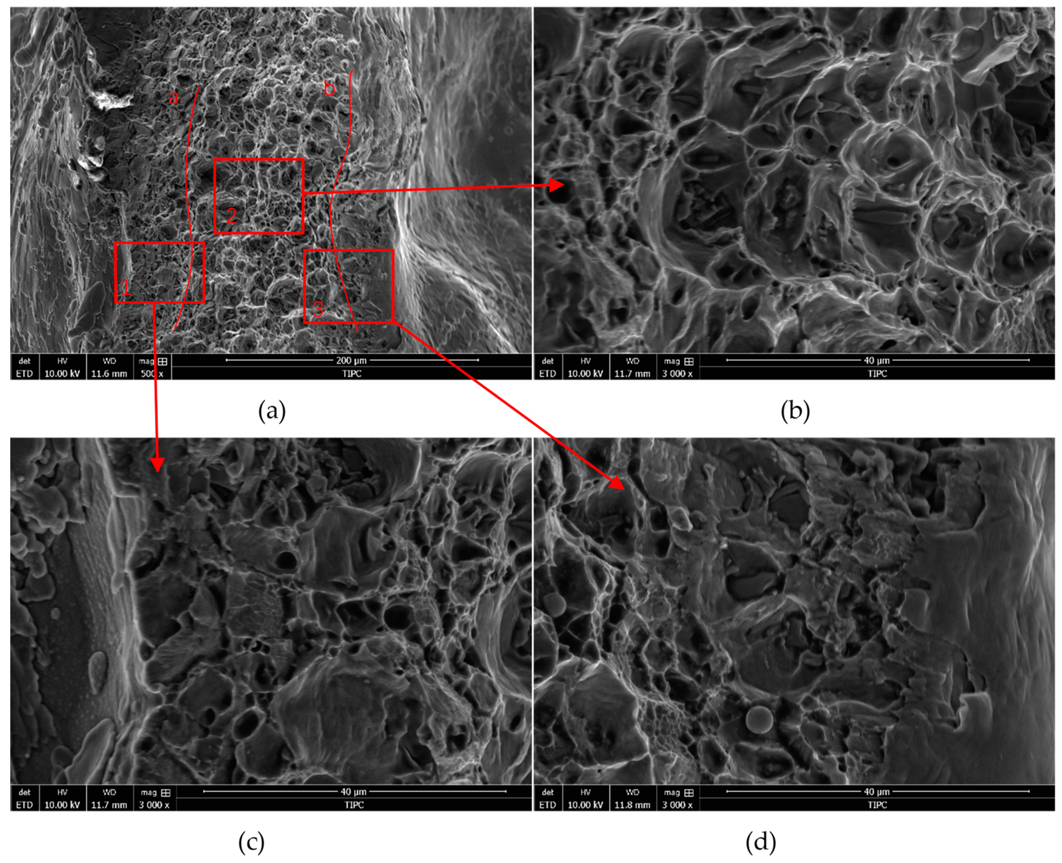
3.3. Fracture Morphology

With the increase of the ablation area, the fracture cross section of the specimen presented three morphologies (Figure 4). They were 45° oblique fracture, U-shaped fracture, and flat fracture. When the section presented 45° oblique fracture, there were some fibrous structures on the surface and an obvious necking phenomenon. With the increase of holes, the fracture became a U-shaped fracture, and part of the fibrous structure still existed on the section. The necking phenomenon was not as good as in the 45° oblique fracture. When there were more ablation holes on the surface of the specimen, the connection between the holes was reduced, the necking phenomenon became very insignificant, and the section became a flat fracture.
As a metal material with strong plasticity, the fracture mode of the aluminum alloy is shear fracture. When subjected to axial tensile force, the material will slip along the slip surface in the direction of the maximum shear stress, and the fracture presents a 45° angle. When there is a laser ablation hole on the surface of the specimen and the hole is considered a crack, the specimen is subjected to the maximum stress at the maximum cross-section of the ablated hole. The stress concentration phenomenon occurs around the small hole. The local area of the specimen is in a three-dimensional stress state, which restrains the development of plastic deformation. Micro-cracks are first generated there, and they grow outward along the direction of stress concentration, eventually leading to the fracture of the material. A flat positive fracture was produced in the central part of the specimen where the micro-cracks were first generated. At the edge area where the stress concentration was less influential, oblique fractures were produced, resulting in a U-shaped fracture. With the further increase in the number of ablation holes, the area of the joint part of the specimen was drastically reduced and the stress concentration first caused the material to break positively, resulting in a flat fracture.
Figure 5a shows a 500× magnified image of the section, and on the side of the image, the edges of the hole are sharp and flat, and inside the ablation hole, there are signs of fluid flow. Therefore, we believe there is a large amount of recast layer in the inner wall of the ablation hole. Inside the ablation hole, a small number of transverse micro-cracks were also found, which indicates that during the recrystallization of the molten aluminum alloy, there was an uneven internal stress along the axial direction of the ablation holes because the temperature of the melt at the bottom of the ablation hole was higher than the temperature of the melt at the outlet. The surface tension of the melt in the two regions was different, resulting in a stress difference in the axial direction, which in turn produced micro-cracks. In the central part of the image, there are dimple and cleavage fractures within the same fracture. To further understand the details of this part, we chose three areas for photographing. Zone 2 magnified images are shown in Figure 5b. Here, the dimple size in the middle part is relatively uniform; the dimple is very dense in the left part of the image, and the depth of the dimple is less than that in the middle part. The enlarged images of zone 1 and zone 3 are shown in Figure 5c and Figure 5d, respectively. These two regions show a fracture similar to a river pattern, with the characteristics of quasi-cleavage fracture. There is a clear and uniform demarcation line between zone 1 and zone 3 with the ductility fracture zone. The demarcation between the quasi-cleavage fracture and ductility fracture is marked in Figure 5a. Zone 1 and zone 3 are the regions of recrystallization of the molten aluminum alloy, and their width is about 30 µm, i.e., during the interaction between the millisecond laser and the aluminum alloy, the melt range of the edge was about 30 µm and the depth of the microcrack did not exceed 30 µm.
Figure 6a shows a 500× magnified image of the section. Compared with the morphology of holes ablated by the millisecond laser, the holes ablated by the nanosecond laser are very uneven and the boundary is not clear nor sharp. Inside the ablation hole, there is a dense distribution of bumpy structures because the nanosecond laser ablation rate is slower and the molten material is less. The melt cools and crystallizes during the movement of the hole wall under the plasma recoil pressure, forming a dense bumpy structure. When observing the central part of the image, we found that the cross-sectional structure was all dimple fracture pattern, which is typical of a ductile fracture. To further understand the details of this part, three zones were also selected for photographing. Zone 2 magnified images are shown in Figure 6b. Here the size of the dimple in the middle part is relatively uniform, whereas the size of the dimple on both sides is smaller. The enlarged images of zone 1 and zone 3 are shown in Figure 6c,d, respectively. There is a clear and uniform demarcation line between them and the larger-sized dimple area, and the demarcation between the large and small dimple is marked in Figure 6a. Under the ablation of laser, the grain size of this part becomes smaller due to the increase of temperature, which leads to the decrease of dimple size. The width of this region is about 40 µm, indicating that during the interaction of the nanosecond laser with the aluminum alloy, the size of the molten region is about 40 µm.

4. Conclusions

In this paper, the mechanisms of material tensile strength changes caused by ablation of aluminum alloy specimens by nanosecond and millisecond lasers were mainly investigated, and the following conclusions were drawn.
(a)
The tensile strength of the material after drilling is higher with nanosecond lasers compared to millisecond lasers. This is due to the higher level of residual compressive stress generated by the nanosecond laser drilling process than by the millisecond laser drilling process.
(b)
After laser drilling, the plasticity of the aluminum alloy is significantly reduced, and the heat affect zone of the fracture has the characteristics of a cleavage fracture. The stress concentration around the small hole is the main factor that causes the reduction of the plastic deformation of the material, while the reduction of the strength of the material is mainly attributed to the reduction of the cross-sectional area of the sample.
(c)
For aluminum alloy materials with a thickness of less than 2 mm, the affected area in the laser drilling process is in the order of microns, and the influence of larger size samples can be ignored.
The above conclusions provide an alternative direction for the parameter optimization of laser drilling, which is an important point of reference for the study of how to ensure the strength and plasticity of the components after laser drilling.

Author Contributions

Conceptualization, Y.W. and J.Y.; methodology, J.Y. and H.G.; formal analysis, Y.W. and H.G.; investigation, Y.W., H.G., L.L. and B.D.; resources, L.L. and B.D.; data curation, H.G.; writing—original draft preparation, H.G.; writing—review and editing, H.G. and Y.W.; supervision, S.L. and M.L.; project administration, S.L. and M.L.; funding acquisition, Y.W. and J.Y.. All authors have read and agreed to the published version of the manuscript.

Funding

This research received no external funding.

Data Availability Statement

Not applicable.

Conflicts of Interest

The authors declare no conflict of interest.

References

  1. Gower, M.C. Industrial applications of laser micromachining. Opt. Express 2000, 7, 56–67. [Google Scholar] [CrossRef] [PubMed]
  2. Li, Z.Y.; Wei, X.T.; Guo, Y.B.; Sealy, M. State-of-art, challenges, and outlook on manufacturing of cooling holes for turbine blades. Mach. Sci. Technol. 2015, 19, 361–399. [Google Scholar] [CrossRef]
  3. Marimuthu, S.; Smith, B.; Kiely, A.; Liu, Y. Delamination-free millisecond laser drilling of thermal barrier coated aerospace alloys. J. Laser Appl. 2019, 31, 042001. [Google Scholar] [CrossRef]
  4. Wang, C.; Wang, Q.; Qian, Q.; Di, B. The development of laser drilling: A review. In IOP Conference Series: Materials Science and Engineering; IOP Publishing: Bristol, UK, 2020; Volume 782, p. 022067. [Google Scholar] [CrossRef]
  5. Schulz, W.; Eppelt, U.; Poprawe, R. Review on laser drilling I. Fundamentals, modeling, and simulation. J. Laser Appl. 2013, 25, 012006. [Google Scholar] [CrossRef]
  6. Wang, X.; Michalowski, A.; Walter, D.; Sommer, S.; Kraus, M.; Liu, J.; Dausinger, F. Laser drilling of stainless steel with nanosecond double-pulse. Opt. Laser Technol. 2009, 41, 148–153. [Google Scholar] [CrossRef]
  7. Voisey, K.; Kudesia, S.; Rodden, W.; Hand, D.; Jones, J.; Clyne, T. Melt ejection during laser drilling of metals. Mater. Sci. Eng. A 2003, 356, 414–424. [Google Scholar] [CrossRef]
  8. Shen, N.; Bude, J.D.; Ly, S.; Keller, W.J.; Rubenchik, A.M.; Negres, R.; Guss, G. Enhancement of laser material drilling using high-impulse multi-laser melt ejection. Opt. Express 2019, 27, 19864–19886. [Google Scholar] [CrossRef] [PubMed]
  9. Ng, G.; Li, L. The effect of laser peak power and pulse width on the hole geometry repeatability in laser percussion drilling. Opt. Laser Technol. 2001, 33, 393–402. [Google Scholar] [CrossRef]
  10. Rubio-González, C.; Ocaña, J.; Gomez-Rosas, G.; Molpeceres, C.; Paredes, M.; Banderas, A.; Porro, J.; Morales, M. Effect of laser shock processing on fatigue crack growth and fracture toughness of 6061-T6 aluminum alloy. Mater. Sci. 2004, 386, 291–295. [Google Scholar] [CrossRef]
  11. Jiang, Y.; Sha, D.; Jiang, W.; He, Y.; Jin, H. A study on failure mechanisms and formability of aluminum alloy sheets under laser shock forming. Int. J. Adv. Manuf. Technol. 2019, 101, 451–460. [Google Scholar] [CrossRef]
  12. Yilbas, B.; Akhtar, S. Laser bending of metal sheet and thermal stress analysis. Opt. Laser Technol. 2014, 61, 34–44. [Google Scholar] [CrossRef]
  13. Yilbas, B.S.; Ageeli, N. Thermal stress development due to laser step input pulse heating. J. Therm. Stresses 2006, 29, 721–751. [Google Scholar] [CrossRef]
  14. Tunna, L.; O’Neill, W.; Khan, A.; Sutcliffe, C. Analysis of laser micro drilled holes through aluminium for micro-manufacturing applications. Opt. Lasers Eng. 2005, 43, 937–950. [Google Scholar] [CrossRef]
  15. Mishra, S.; Yadava, V. Modeling and optimization of laser beam percussion drilling of thin aluminum sheet. Opt. Laser Technol. 2013, 48, 461–474. [Google Scholar] [CrossRef]
  16. Schneider, M.; Muller, M.; Fabbro, R.; Berthe, L. Study of hole properties in percussion regime with a new analysis method. In Proceedings of the International Congress on Applications of Lasers & Electro-Optics, Scottsdale, AZ, USA, 30 October–2 November 2006. [Google Scholar] [CrossRef] [Green Version]
  17. Mishra, S.; Yadava, V. Prediction of material removal rate due to laser beam percussion drilling in aluminium sheet using the finite element method. Int. J. Mach. Mach. Mater. 2013, 14, 342–362. [Google Scholar] [CrossRef]
  18. Guinard, C.; Montay, G.; Guipont, V.; Jeandin, M.; Girardot, J.; Schneider, M. Residual Stress Analysis of Laser-Drilled Thermal Barrier Coatings Involving Various Bond Coats. In Proceedings of the International Thermal Spray Conference. German Welding Soc DVS, Barcelona, Spain, 21–23 May 2014. [Google Scholar] [CrossRef]
Figure 1. Experimental setup. (a) Experimental setup and process, (b) sample drawing; unit: mm.
Metals 12 02049 g001
Figure 2. Variation of the rate of change of strength and tensile strength with the ablation area ratio for nanosecond and millisecond laser ablation of aluminum alloys.
Metals 12 02049 g002
Figure 3. Elongation of nanosecond and millisecond laser ablated aluminum alloys as a function of ablation area ratio.
Metals 12 02049 g003
Figure 4. Tensile fracture morphology of specimens with different number of holes by laser ablation, (a) 45° oblique fracture, (b) U-shaped fracture, (c) flat fracture. The top right corner of the image shows a diagram of fracture morphology.
Metals 12 02049 g004
Figure 5. SEM images of millisecond laser ablation of aluminum alloy fractures. (a) is the 500× magnified image of the fracture, (b) is the 3000× magnified image of zone 2, (c) is the 3000× magnified image of zone 1, and (d) is the 3000× magnified image of zone 3. The lines corresponding to letters a, b and c are the demarcation lines between the two morphologies.
Metals 12 02049 g005
Figure 6. SEM images of nanosecond laser ablation of aluminum alloy fractures. (a) is the 500× magnified image of the fracture, (b) is the 3000× magnified image of zone 2, (c) is the 3000× magnified image of zone 1, and (d) is the 3000× magnified image of zone 3. The lines corresponding to letters a and b are the demarcation lines between the two morphologies.
Metals 12 02049 g006
Table 1. Laser parameters.
Laser
Source
Laser Wave LengthLaser
Energy
Pulse Duration
(FWHM)
Pulse Repetition RateNumber of Pulses
ms laser1064 nm8.8 J0.5 ms1 Hz3
ns laser1064 nm0.66 J8 ns10 Hz200
Publisher’s Note: MDPI stays neutral with regard to jurisdictional claims in published maps and institutional affiliations.

