Abstract
A novel horizontal moving-bed ironmaking process has been developed at the University of Utah. This process uses iron concentrate directly without sintering or pelletization and reduces it with hydrogen in the temperature range of 500–1000 °C. The work started with the determination of the particle kinetics, which was then combined with diffusional effects to analyze the reduction rate of a particle bed. Based on the kinetics formulation, a mathematical model of the furnace for the proposed technology was developed for a modest industrial ironmaking operation designed to produce iron at a rate of 0.1 Mtpy.
1. Introduction
In 2019, a total of 1.4 billion metric tons of crude iron was produced worldwide, and about 92% of it was made with a blast furnace (BF) [1]. BF ironmaking that uses iron concentrates requires the sintering/pelletization of iron ore, coke making, and reduction in a shaft furnace. At the current rate of production, BFs are responsible for the largest greenhouse gas emissions of any industry [2], and the demand for steel will rise in the years to come [3]. Alternate processes that consume less energy and emit less CO2 are being developed [4,5,6,7,8,9]. Some of these processes have been successfully commercialized [10] by replacing the coke making process, lowering energy requirements and CO2 emissions, and using iron ore fines or concentrates directly without pelletization. In spite of the recent successes in alternative ironmaking, BF technology is still the predominant industrial method.
2. Process Concept
The direct use of iron concentrates was one of the main features of the recently developed Flash Ironmaking Technology (FIT) [4,5,6,7,8,9], which is suitable for a large-scale ironmaking plant [4,5,6,7].
For medium-level steelmaking operations, sponge iron would make a suitable feed. Direct use of iron concentrate with its high reactivity would be advantageous. Based on this reasoning, a moving-bed reactor to directly reduce concentrate has been proposed [11].
3. Configuration of a Horizontal Moving-Bed Furnace
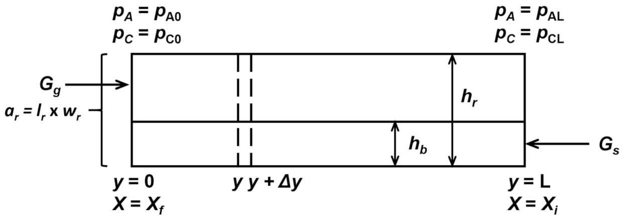
The furnace to be used for the proposed process would continuously carry iron concentrate placed as a layer on a tray or a layer of pellets or blocks on the moving grate. The reducing gas is fed into the reactor in a counter-current flow. The furnace may be designed to accommodate multiple trays or layers stacked on top of each other. A sketch of such a counter-current moving-bed reactor is shown in Figure 1.

Figure 1.
Sketch of a counter-current horizontal moving-bed reactor. pA and pC are the partial pressures of H2 and H2O, respectively; Gg and Gs are the total input rate per unit cross-sectional area of the reactor of gas (including hydrogen, water vapor, and inert gas, if any) and the input molar rate per unit cross-sectional area of the reactor of solid B, respectively; y is the distance from the gas inlet; X is the fractional removal of oxygen from iron oxide; and a represents the cross-sectional area of the reactor.
In order to evaluate the realistic feasibility of such a moving bed for direct reduction of iron concentrate, a quantitative analysis of its potential performance is necessary. This requires information on the kinetics of reduction of concentrate particles, that of a particle bed (including diffusional effects), and finally, a mathematical model of the moving-bed reactor.
4. Hydrogen Reduction Kinetics of Concentrate Particles
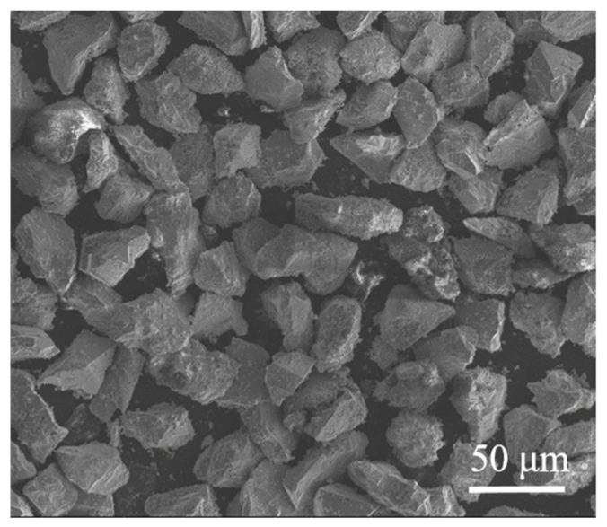
The reduction kinetics of iron ore concentrate particles were measured in the temperature range expected for the proposed process using a home-made thermogravimetric analysis (TGA) unit [12]. The magnetite concentrate used in this work was from the Mesabi Range in the U.S. and had a size of <100 μm. Figure 2 illustrates a SEM picture of these particles.
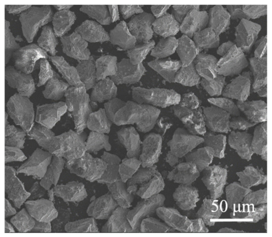
Figure 2.
SEM micrograph of concentrate particles.
The magnetite concentrate was provided by ArcelorMittal (East Chicago, USA). The chemical analysis of the concentrate is detailed in Table 1.

Table 1.
Chemical Composition of Magnetite Concentrate Particles.
The thermogravimetric analysis (TGA) unit used to measure the rate of reduction is depicted in Figure 3.
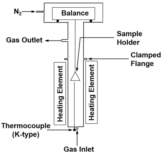
Figure 3.
Diagram of TGA unit.
A thin layer of particles weighing 190–510 mg was placed on a shallow sample container. The reducing gas mixture was injected at a sufficient rate to eliminate the mass transfer effects.
The rate equations for the hydrogen reduction of iron concentrate, formulated from the experimental data, are given for different temperature ranges as follows:
In the range 800–1000 °C,
In the range 650–800 °C,
In the range 500–650 °C,
where X is fractional conversion of iron oxide, R is 8.314 J∙mol−1K−1, T is in K, p is in atm, and t is in seconds. It should be noted that the rate decreased with temperature in the range 650–800 °C. This phenomenon has been observed previously [13,14,15,16] for iron oxide reduction.
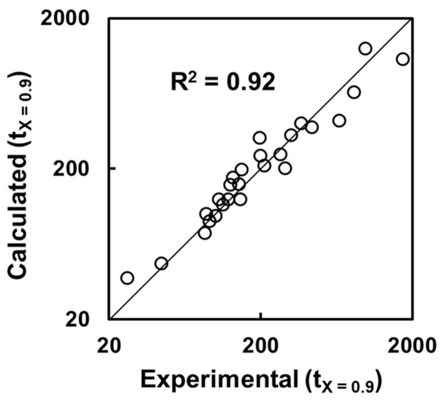
The iron is refined in the steelmaking step, and thus, the iron just needs to be reduced to a degree of 90% or higher. The results of the rate equations were compared with experimental data for 90% conversion, as shown in Figure 4. The agreement is good. Details of the comparison are given elsewhere [12].

Figure 4.
Comparison of time for 90% conversion from the rate equations with experimental data. Time is in seconds.
5. Incorporation of Interparticle Diffusion in the Rate Analysis
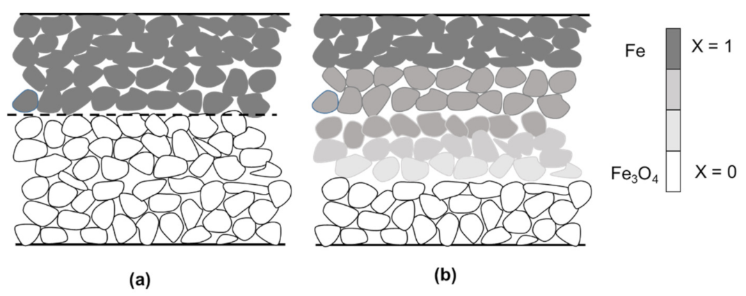
In a particle bed in the moving-bed furnace, the reduction is likely to take place under the effect of diffusion between the particles, as illustrated in Figure 5. It is important to be able to predict the temperature at which mass transfer begins to strongly affect the reduction rate of the particle bed as well as to estimate its quantitative effect.

Figure 5.
Illustration of the reaction of a flat bed of particles under (a) one-step diffusion control and (b) mixed control.
Figure 5 depicts a reaction under diffusion control or mixed control.
To determine and incorporate such diffusional effects, experiments were performed with deeper beds of concentrate of predetermined depths [12]. The experimental data were converted to a closed-form X-t relation using Sohn’s law of additive reaction times [17,18,19,20], which is applicable under the general conditions of mixed control. Sohn’s law of additive reaction times [17,18,19,20] states that for isothermal reactions, the time needed for a certain degree of conversion is the sum of the time needed in the absence of any diffusional effect and the time needed under the control of pore diffusion and external mass-transfer:
or mathematically,
where a is a constant related to the rate constant of particle kinetics and is a fluid–solid reaction modulus. The expressions of a and g(X) for hydrogen reduction of magnetite concentrate particles can be obtained from the following particle kinetics presented earlier:
Time required to attain a certain conversion ≅ Time required to attain the same conversion under the condition of rapid interparticle diffusion + Time required to attain the same conversion under the control of interparticle diffusion and external mass transfer
In the range 800–1000 °C,
In the range 650–800 °C,
In the range 500–650 °C,
where R is 8.314 J∙mol−1K−1, T is in K, p is in atm, and t is in seconds.
as the conversion function for the diffusion-controlled conditions given by
where Fp is a shape factor, which has a value of 3 for a sphere and 1 for a flat bed.
The fluid–solid reaction modulus is defined as follows:
Sh* is the modified Sherwood number, defined as follows:
where km is the mass transfer coefficient.
A good agreement was found [12] between the experimental data and the results from the application of Sohn’s Law, which renders unnecessary numerical solution of the differential equations.
6. Design of a Horizontal Moving-Bed Furnace
6.1. Model Formulation
The model has been formulated based on the configuration of the countercurrent moving-bed reactor presented in Figure 1.
The conditions for modeling the counter-current moving bed reactor are as follows:
- (a)
- The overall reaction is , which in general notation is represented by .
- (b)
- The reduction occurs under isothermal conditions.
- (c)
- The solid and reducing gas are in plug flow and steady state.
- (d)
- The reactor has a uniform cross-sectional area.
- (e)
- Mass transfer between the gas and the top of the bed is fast.
The details of the model formulation can be found elsewhere [12]. Here, the final result of the formulation that relates the reactor length to all other reactor parameters and operating conditions is presented as follows:
where
and
In the above equations, Xo is the final value of X at the gas entrance; Gg and Gs are the total input rate per unit cross-sectional area of the reactor of gas (including hydrogen, water vapor, and inert gas, if any) and the input molar rate per unit cross-sectional area of the reactor of solid B, respectively; K is the equilibrium constant for wüstite reduction; x is the mole fraction of gaseous species; n = 1.5 is the Avrami parameter in the nucleation-and-growth kinetics equation; ko is the pre-exponential factor in the rate equation; P is the total pressure of the gas phase; εp is the porosity of the product iron layer; and ρB is the true molar density of B.
The integral in Equation (13) can be evaluated using Simpson’s Rule. At X = 0, the integrand goes to infinity due to the nature of the nucleation-and-growth kinetic equation. Therefore, the integration was carried out starting with a small positive value of X = δ. This small value δ was reduced until the calculated value of the length of the reactor, L, was unaffected by a further decrease in the value of δ.
6.2. Design of Industrial Reactors
An industrial ironmaking reactor—producing 0.1 million metric tons of iron per year (Mtpy), equivalent to 12.66 metric tons/h assuming operation of 24 h/day and 330 days/year—was designed. The reactor will produce iron of Xo = 0.95. The normalized driving force of reducing gas, θ, is set at 0.3 at the gas outlet. The reactor is assumed to have a width of 5 m and a height of 3 m.
From the kinetics of magnetite reduction, it was determined that between 650 and 1000 °C, a bed with a thickness of 1 cm would largely be controlled by diffusion. Thus, this reactor design uses a bed thickness equal to or greater than 1 cm. For the purpose of this work, the reactor will have 10 layers at most. For the dimensions of a horizontal moving-bed reactor to be comparable with other industrial reactors, the length of the reactor should be under 50 m.
For a production rate of 0.1 Mtpy, the effects of temperature and bed thickness on residence time, reactor length, bed speed, and gas velocity are shown in Table 2. For a given bed thickness, the residence time and the reactor length decreased with increasing temperature. The bed speed was unaffected by temperature, as expected from the diffusion-controlled reaction conditions. The gas velocity increased slightly with decreasing temperature. For a given temperature, increasing the bed thickness resulted in a longer residence time, longer reactor length, and slower speed of moving bed. The linear gas velocity also increased with increasing layer thickness as the free board in the reactor decreased. The demand for gas increased with decreasing temperature as the composition of hydrogen–water vapor mixture in equilibrium in a wüstite-iron system became more hydrogen rich.
Table 2.
Effect of bed thickness and temperature on residence time, reactor length, speed of bed, and gas velocity for a moving-bed reactor with a production rate of 0.1 Mtpy.
It was found that a reactor with a bed thickness of 2 cm and length of 45.6 m can operate at a temperature as low as 650 °C. The design parameters and operating conditions of the reactor were calculated at different temperatures for reactors operating with a bed thickness of 2 cm, as shown in Table 3.
Table 3.
Design parameters or operating conditions for horizontal moving-bed reactors (0.1 Mtpy) at different temperatures.
7. Concluding Remarks
The work presented in this paper on the development of a horizontal moving-bed reactor based on the proposed technology can be summarized as follows:
- (1)
- The proposed technology for a modest-scale ironmaking operation with a production rate of 0.1 Mtpy can be operated at temperatures between 650 and 1000 °C.
- (2)
- The design parameters and the operating conditions for the horizontal moving-bed reactor were established.
- (3)
- A simple model for a moving-bed reactor that indicated that the proposed ironmaking technology has industrial potential was formulated.
Author Contributions
Conceptualization, H.Y.S.; methodology, H.Y.S. and S.R.; software, S.R.; validation, H.Y.S. and S.R.; formal analysis, H.Y.S. and S.R.; investigation, H.Y.S. and S.R.; resources, H.Y.S. and S.R.; data curation, S.R.; writing—original draft preparation, H.Y.S. and S.R.; writing—review and editing, H.Y.S. and S.R.; visualization, S.R.; supervision, H.Y.S.; project administration, H.Y.S.; funding acquisition, H.Y.S. All authors have read and agreed to the published version of the manuscript.
Funding
This research was funded by a University of Utah internal unrestricted research fund.
Institutional Review Board Statement
Not applicable.
Informed Consent Statement
Not applicable.
Data Availability Statement
Additional data can be found in Ref. [12].
Conflicts of Interest
The authors declare no conflict of interest.
References
- WorldSteel Association. Steel Statistical Yearbook 2020. Available online: https://worldsteel.org/wp-content/uploads/Steel-Statistical-Yearbook-2020-concise-version.pdf (accessed on 25 October 2022).
- Hasanbeigi, A.; Arens, M.; Price, L. Alternative Emerging Ironmaking Technologies for Energy-Efficiency and Carbon Dioxide Emissions Reduction: A Technical Review. Renew. Sustain. Energy Rev. 2014, 33, 645–658. [Google Scholar] [CrossRef]
- Bellevrat, E.; Menanteau, P. Introducing Carbon constraint in the Steel Sector: ULCOS Scenarios and Economic Modeling. Revue de Métallurgie 2009, 106, 318–324. [Google Scholar] [CrossRef]
- Sohn, H.Y. Suspension Ironmaking Technology with Greatly Reduced Energy Requirement and CO2 Emissions. Steel Times Int. 2007, 31, 68–72. [Google Scholar]
- Sohn, H.Y.; Mohassab, Y. Development of a Novel Flash Ironmaking Technology with Greatly Reduced Energy Consumption and CO2 Emissions. J. Sustain. Metall. 2016, 2, 216–227. [Google Scholar] [CrossRef]
- Sohn, H.Y.; Fan, D.-Q.; Abdelghanyand, A. Design of Novel Flash Ironmaking Reactors for Greatly Reduced Energy Consumption and CO2 Emissions. Metals 2021, 11, 332. [Google Scholar] [CrossRef]
- Sohn, H.Y.; Elzohiery, M.; Fan, D.-Q. Development of the Flash Ironmaking Technology (FIT) for Green Ironmaking with Low Energy Consumption. J. Energy Power Technol. 2021, 3, 26. [Google Scholar] [CrossRef]
- Patisson, F.; Mirgaux, O. Hydrogen Ironmaking: How It Works. Metals 2020, 10, 922. [Google Scholar] [CrossRef]
- Pei, M.; Petäjäniemi, M.; Regnell, A.; Wijk, O. Toward a Fossil Free Future with HYBRIT: Development of Iron and Steelmaking Technology in Sweden and Finland. Metals 2020, 10, 972. [Google Scholar] [CrossRef]
- Ghosh, A.; Chatterjee, A. Ironmaking and Steelmaking Theory and Practice, 4th ed.; PHI Learning Private Ltd.: New Delhi, India, 2011; pp. 225–262. [Google Scholar]
- Sohn, H.Y.; Roy, S. Moving-Bed Reactor for Continuous Ironmaking with Gaseous Reduction of Iron Ore Concentrate. Provisional. U.S. Patent Application No. 63/389,795, 15 July 2022. [Google Scholar]
- Roy, S. Hydrogen Reduction of Iron Ore Concentrate in Loose Layers and Compacts. Ph.D. Thesis, University of Utah, Salt Lake City, UT, USA, 2022. [Google Scholar]
- Themelis, N.J.; Gauvin, W.H. Reduction of Iron Oxide in Gas-Conveyed Systems. AIChE J. 1962, 8, 437–444. [Google Scholar] [CrossRef]
- Wang, H.; Sohn, H.Y. Hydrogen Reduction Kinetics of Magnetite Concentrate Particles Relevant to a Novel Flash Ironmaking Process. Metall. Mater. Trans. B 2013, 44, 133–145. [Google Scholar] [CrossRef]
- Lien, H.O.; El-Mehairy, A.E.; Ross, H.U. A Two-Zone Theory of Iron-Oxide Reduction. J. Iron Steel Inst. 1971, 209, 541–545. [Google Scholar]
- Specht, O.G.; Zappfe, C.A. The Low-Temperature Gaseous Reduction of Magnetite Ore to Sponge Iron. Trans. Am. Inst. Min. Metall. Engrs. 1946, 167, 237–280. [Google Scholar]
- Sohn, H.Y.; Roy, S. Fluid–Solid Reaction Kinetics for Solids of Non-Basic Geometries: Application of The Law of Additive Times in Combination with the Shape-Factor Method. Metall. Mater. Trans. B 2020, 51, 601–610. [Google Scholar] [CrossRef]
- Sohn, H. Fluid–Solid Reactions; Elsevier: Cambridge, MA, USA, 2020; pp. 233–241. [Google Scholar]
- Sohn, H.Y. The Law of Additive Reaction Times in Fluid–Solid Reactions. Metall. Mater. Trans. B 1978, 9, 89–96. [Google Scholar] [CrossRef]
- Sohn, H.Y. Review of Fluid-Solid Reaction Analysis: Part 2. Single Porous Reactant Solid. Can. J. Chem. Eng. 2019, 97, 2068–2076. [Google Scholar] [CrossRef]

Publisher’s Note: MDPI stays neutral with regard to jurisdictional claims in published maps and institutional affiliations. |
© 2022 by the authors. Licensee MDPI, Basel, Switzerland. This article is an open access article distributed under the terms and conditions of the Creative Commons Attribution (CC BY) license (https://creativecommons.org/licenses/by/4.0/).