Article

Shock Hugoniot of Forged and Additively Manufactured 304L Stainless Steel

1
Nevada National Security Site, New Mexico Operations, Los Alamos, NM 87544, USA
2
Nevada National Security Site, Nevada Operations, Las Vegas, NV 89030, USA
3
MPA-CINT, Los Alamos National Laboratory, Los Alamos, NM 87545, USA
4
T-3, Los Alamos National Laboratory, Los Alamos, NM 87545, USA
*
Authors to whom correspondence should be addressed.
Metals 2022, 12(10), 1661; https://doi.org/10.3390/met12101661
Submission received: 7 September 2022 / Revised: 27 September 2022 / Accepted: 29 September 2022 / Published: 2 October 2022
(This article belongs to the Special Issue Dynamic Response of Metals under Extreme Conditions)

Abstract

:
The purpose of this research was to measure the equation of state for additively manufactured (AM) and forged 304L stainless steel using a novel experimental technique. An understanding of the dynamic behavior of AM metals is integral to their timely adoption into various applications. The Hugoniot of the AM 304L was compared to that of the forged 304L at particle velocities where the material retains a two-wave structure. This comparison enabled us to determine the sensitivity of the equation of state to microstructure as varied due to processing. Our results showed that there was a measurable difference in the measured shock velocity between the AM and forged 304L. The shock wave velocities for the AM 304L were found to be ~3% slower than those for the forged 304L at similar particle velocities. To understand these differences, properties such as densities, sound speeds, and texture were measured and compared between the forged and AM materials. Our results showed that no measurable difference was found in these properties. Additionally, it is possible that differing elastic wave amplitudes may influence shock velocity

1. Introduction

Additive manufacturing (AM) is a new process for manufacturing metals in an efficient and robust manner which shows great promise for real-world applications. AM materials are becoming more prevalent in various fields because they offer some advantages over conventionally manufactured materials. For example, using AM parts can be printed to near net shape in a relatively short time with minimal machining, which can accelerate the process of producing prototypes. It is also relatively easy to make changes to part designs on the fly using AM. However, there are new challenges associated with AM especially related to determining the suitability of the materials generated in this process to actual applications. While there has been a plethora of research to characterize the microstructure and mechanical properties of AM materials as a function of strain rate [1,2,3,4], there have only been a handful of studies investigating the dynamic properties such as spall strength and equation of state [5,6,7,8,9] of AM materials. These complex loading regimes that subject AM materials to extreme mechanical loads are of potential interest to various applications. The goal of this work is to systematically measure the shock velocity of additively manufactured 304L stainless steel (SS).
In the past few years, tremendous efforts have been made to investigate the microstructure and properties of additively manufactured metals [10,11]. Many groups have investigated the yield strength and failure mechanisms in AM steels using quasi-static mechanical tests and have coupled them with a thorough characterization of the microstructure [1,2,3,5,6,7,8,9,10,11,12,13,14]. Specifically, Carlton et al. [15] performed tensile tests to establish relationships between pre-existing porosity and fracture mechanisms in austenitic SS. This work showed that cracks during failure initiated at pre-existing voids in AM materials with large porosity distributions. Similar work to establish relationship between pre-existing defects and properties were also performed by Yasa, Verlee, and Cherry [10,12,13]. Aref Yadollahi et al. [16] studied formation of tensile damage evolution in AM SS and noted that the coalescence of voids was the main mechanism of damage in AM parts, an effect that was more pronounced at higher levels of initial porosity. They also quantified the mechanical behavior and parameterized an internal state variable-based plasticity damage model to demonstrate relationships between damage and the microstructure. Rottger et al. [17] investigated the effect of processing parameters on the resulting microstructure and mechanical properties during the selective laser melting process (SLM) and compared it with samples that were subjected hot isostatic pressing to reduce porosity. More recently, Thoma et al. [18] have developed a high-throughput approach to investigate the relationships between build parameters, microstructure and properties for SLM. They have developed a dimensionless parameter to correlate process parameters to the expected density of components without need for extensive modeling or experimentation [19]. In addition to build parameters, the orientation of the build can also affect tensile properties of materials as shown by Simonelli et al. [20]. There are multiple examples of such studies using various AM techniques in many materials to explore structure-property relationships [21].
While many studies exist to understand the specific microstructure and the resulting properties at low strain rates, there are only a handful of studies on the dynamic behavior of AM materials [5,6,7,8,22]. Gray et al. [8] performed spall experiments on AM 316 L SS and found that while the spall strength of these materials was higher than their wrought counterpart, there was also a change in the damage morphology between the two materials. This work also investigated the effect of annealing on the dynamic response of AM materials and showed that post-processing of materials can drastically alter mechanical properties. Jones et al. [6] investigated the spall strength of AM Ti-6Al-4V and found the spall strength to be dependent on the sample orientation with respect to the build layer thickness. Specifically, the spall strength was much higher when samples were loaded parallel versus normal to the AM build layer interfaces. Fadida et al. [23] studied Ti-6Al-4V and examined the effects of initial porosity on dynamic strength, finding that denser samples displayed greater strength, while ductility remained comparable whether the samples were dense or porous. Jones et al. [7] also investigated the spall strength of AM tantalum and found that while the AM materials had a higher Hugoniot elastic limit their spall strength was lower than wrought tantalum (Ta). This was attributed to the change in the microstructure of the AM Ta that led to the creation of a higher amount of void nucleation sites. As shown above, most of the published work has focused on investigating failure in AM materials. To our knowledge the only previously published study to investigate the equation of state of AM metal under dynamic loading is that of Wise et al. [9] which investigated the equation of state of AM 304L and found no measurable differences in the shock stress of AM vs. wrought 304L. However, Wise et al. did not report directly measured or calculated shock velocity in the stainless samples. This scarcity in experiments investigating the equation of state of AM materials is possibly related to the fact that prior research has shown that equation of state is fairly insensitive to changes in grain size [24], texture and orientation [22,25].
The goal of this work is to fill this gap in knowledge by performing systematic experiments on AM 304L SS. The rest of the paper is organized as follows. Section 2 presents the experimental methods used in this work. The results are presented in Section 3 followed by a discussion of results in Section 4. Finally, a summary of the results is presented in Section 5.

2. Experimental Methodology

To perform dynamic measurements of AM 304L SS, this work used conventional shock compression techniques along with a top-hat method to accurately determine the shock velocity. This top-hat method uses z-cut quartz below its Hugoniot elastic limit as the “brim” so that a single wave travels through the quartz and breaks out at the free surface creating a sharp timing fiducial. Because the metal studied was manufactured with a directional printing technique, this design also allowed for dependence of the equation of state on the orientation of the samples w.r.t the build direction. To achieve this goal, samples were obtained from a manufactured plate in multiple directions as will be discussed later. This section describes the manufacturing process in more detail and elaborates on the experimental techniques used to carefully measure shock and particle velocities.

2.1. Material and AM Processing

Metallic samples can be manufactured by various AM techniques. For example, lasers can be utilized to melt wire samples and build up bulk samples by laying down weldments. This process is very similar to metal inert gas welding methods. Additionally, laser bed powder fusion method uses a high energy laser to fuse metallic powders with a rastering technique can also be used to manufacture AM materials. For this method to work well, it is necessary to start with pure powder with insignificant surface oxide or any pre-existing defects [26]. Process parameters like laser power and hatch spacing must also be optimized to produce samples that are close to full density [18]. Any AM process produces artifacts in the sample that influences crystallographic and grain morphology. For example, there can be an orientation of grains along and normal to the direction of rastering when the powder is fused. In some cases, columnar grains can also be produced. In this work, we used powder bed laser fusion to manufacture the samples.
A single lot of pedigreed micro-melt 304L SS powder (termed ADET powder) manufactured by Carpenter Powder Products in Sweden was used for manufacturing the AM material. A detailed chemistry analysis of this powder is shown in Table 1.
The powder had a chromium-to-nickel equivalent ratio of 1.70, apparent density of 4.20 g/cm3, and tap density of 4.80 g/cm3. The plates fabricated on the GmbH Electro Optical Systems (EOS) M 280 were built on a 50.5 mm thick AISI 304L baseplate in the vertical and horizontal directions as shown in Figure 1. The processing parameters used were the EOS-developed PH1 20 µm settings. This license from EOS was developed specifically for SS and uses rotational rectilinear hatching with 20 µm layer heights. However, due to the proprietary nature of the fabrication method, the only detail that was known during the fabrication was the layer height.
The plate from which samples for the current work were obtained was manufactured by the Sigma Division at Los Alamos National Laboratory (LANL), with raster directions set at 0, 90, and 45 degrees. Plate 2 depicted in Figure 1 (left) was used to obtain samples for the current study. Figure 1 (right) depicts plate 2 and shows the locations from which samples were obtained. These included two large samples in the z-direction and many smaller samples at various orientations. The specific samples studied here are Z1a, X1, XY1(+45), and XY2(+45). The chemical composition from the final plate build was also measured using an outside vendor and is shown in Table 1. It is important to note that no post-build heat treatment was performed on the AM plates. The wrought material used in this study was processed by high energy rate forging [27].
The microstructure of the samples used in this study was characterized using Electron backscatter diffraction (EBSD) [28] and light optical microscopy. Sample preparation consisted of grinding on SiC paper with increasingly finer grit, followed by mechanical polishing with 0.3 µm alpha alumina slurry and then a mixture of 5:1 by volume of 0.04 µm colloidal silica and hydrogen peroxide. Optical microscopy images were acquired at various magnifications using a Zeiss Axio Imager M2m optical microscope of the starting microstructures and those following incipient spallation testing. In preparation for EBSD analysis, the samples were electropolished and very slightly electroetched in a solution of 60% nitric acid and 40% water, at 6 V and 3 V, respectively. EBSD analysis was performed with a step size of 0.25 µm on a Phillips XL30 FEG SEM, using the TSL Data Collection and Analysis software. The microstructure of these AM samples along with a reference microstructure for wrought 304L is shown in Figure 2.
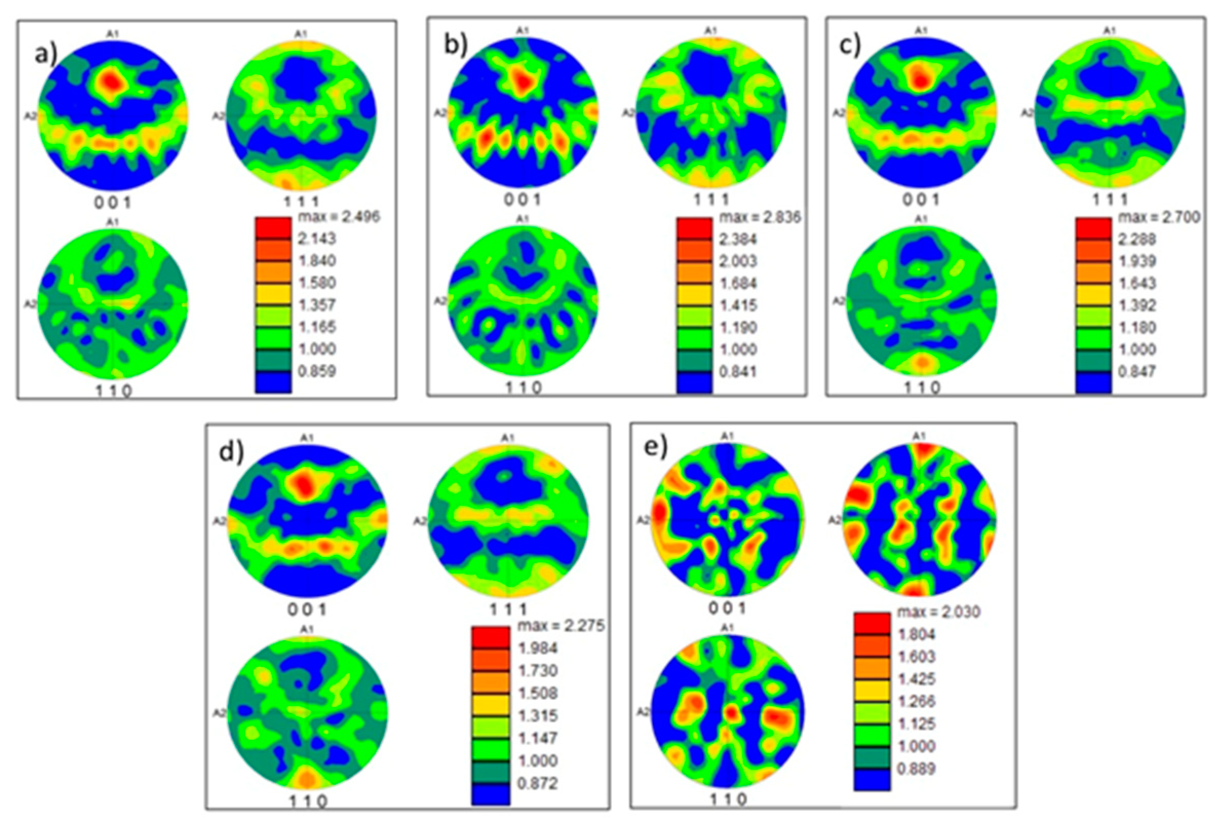
Figure 2 contrasts the microstructure produced on the EOS powder bed AM machine using the pedigreed 304L SS powder with the microstructure of the forged 304L SS. It also shows micrographs for the various sample orientations used in this work. The overall microstructure of the EOS build material is observed to be significantly finer macroscopically than that of the forged material. An equiaxed polycrystalline microstructure typical of many recrystallized metals and alloys is evident in the forged 304L SS. No ferrite phase was observed in the EOS build plate. Figure 3 shows the texture maps associated with the microstructures in Figure 3, expressed in multiple of random (MRD).
All the AM 304L samples have a weak <100> texture. However, the texture for the four AM samples had similar intensities of 2.4 MRD, 2.8 MRD, 2.7 MRD and 2.3 MRD, respectively. This is similar to the 2 MRD texture observed in the forged sample.

2.2. Hugoniot Measurements

Before performing dynamic experiments, it is important to measure certain initial material properties such as sound speed and density in the as-received materials. These measurements help in the design of the dynamic experiments—choice of impactor, sample thickness, etc. A pulse-echo technique was used to measure the longitudinal and shear sound speeds. Density was characterized using immersion techniques. Sound speeds are estimated to be accurate within 0.5%, while immersion densities are estimated to be good to better than 0.5%. Sample thicknesses were measured after the samples were lapped flat and parallel to within 5 to 10 μm. These values are shown in Table 2. It is important to note that it has been documented in the literature that accurately measuring the density of AM samples, especially with porosity, can be complicated especially using standard immersion techniques [29,30,31]. In presence of porosity, liquid can fill the “pores” and cause a larger error in the density measurements [29]. Hence, additional analysis using optical micrographs and X-Ray tomography was also performed on the samples to measure porosity in the samples. This analysis showed a <1% porosity in the samples.
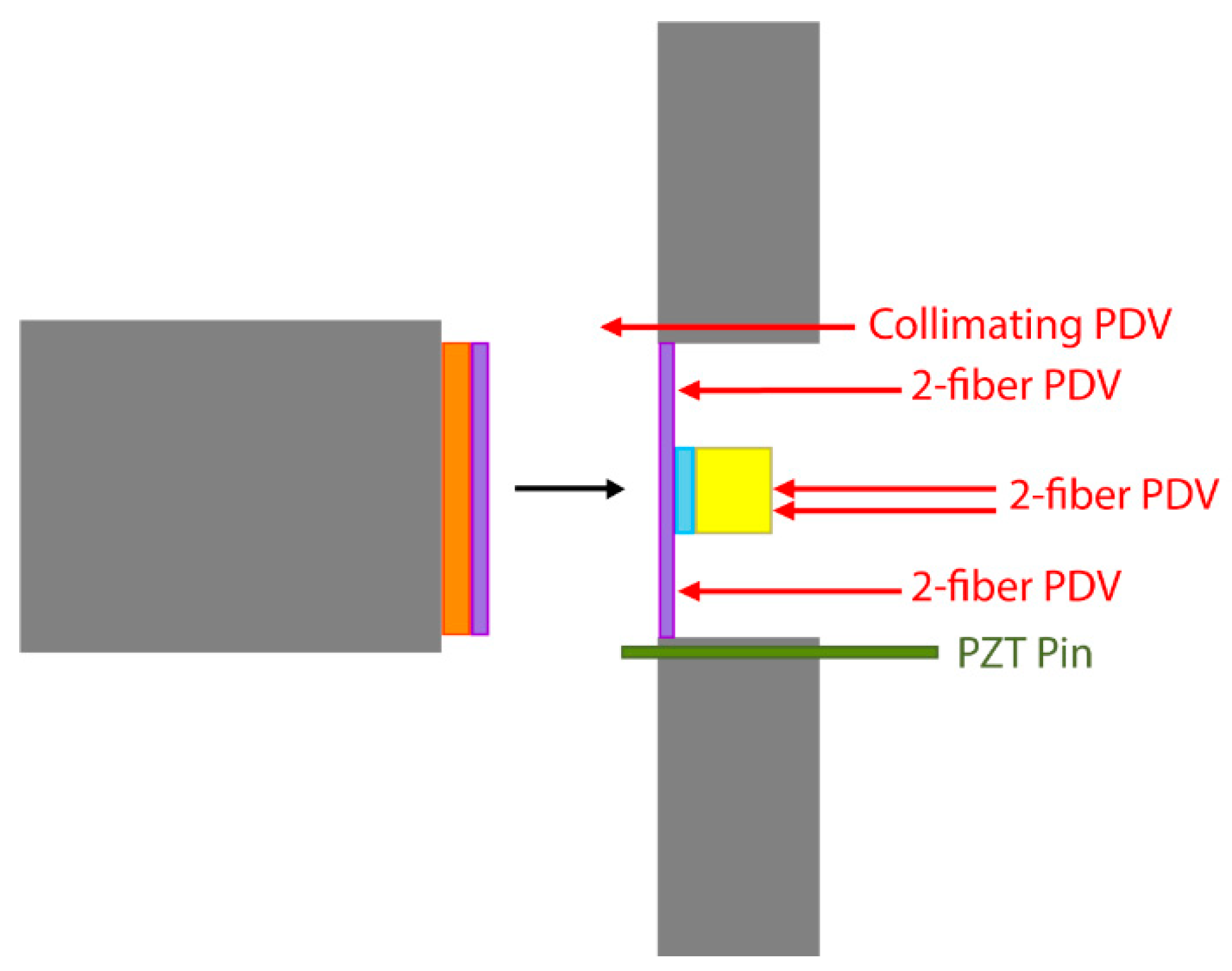
Shock velocities were measured using a top-hat design with a z-quartz baseplate and stainless sample, with z-, xy-, and x-directions of the AM 304L SS material as shown in Figure 1. For these experiments, the impactor was a z-quartz disc backed by syntactic foam bonded directly to the projectile nose. The target was a quartz baseplate with the same dimensions (35 mm diameter by 2 mm thick) as the impactor, and with the sample material (304L) with the same nominal thickness (2 mm) and a smaller diameter (10 mm), bonded to the quartz baseplate using a thin glue bond. Finally, a sapphire window (10 mm diameter by 12 mm thick) was glued to the back of the target to reduce elastic-plastic wave interactions due to reflectance from the free surface. A sketch of this experimental design is shown in Figure 4. These target dimensions were carefully chosen to be sure edge releases (lateral releases) did not affect the velocimetry measurements at the sample/window interface during the desired measurement timescale. This is particularly important because of the use of a sapphire window, a material that is well known to have high wave speeds.
The projectiles were launched at a nominal velocity of 400 m/s. Four 2-fiber photonic Doppler velocimetry (PDV) probes [32] were placed at opposite sides around the brim of the quartz baseplate. These four probes not only acted as accurate timing fiducials for the arrival of the shock wave at the back surface of the 304L sample, but also provided cross-timing information. Because quartz remains elastic in the stress regime of this study, only a single wave propagates into the stainless sample. It is important to note that this technique is limited to stress states below which quartz stays elastic; for z-cut quartz, this is ~8.5 GPa. Timing information from these four “brim” probes is used to calculate the time of shock wave entrance into the center of the stainless sample. Two additional 2-fiber probes illuminated the center of the sample through the sapphire window to provide information regarding the timing of the elastic and plastic waves exiting the sample, one in the center, and one offset by 2.5 mm. The difference between the entrance and exit times of the shock wave provides the transit time for the shock to travel though the sample. This information, coupled with the thickness of the samples, provides measurements for the shock velocity with an accuracy of about one percent (1%).
This quartz top-hat technique is similar to the 13-pin method used by Mitchell and Nellis [33], but at much smaller stress states where there is both two-wave structure, and long risetime plastic waves. Their work used six pins around the base instead of four. Mitchell and Nellis also used an additional pin in the center of the upper surface to determine impactor bow. However, because of the “gentle” nature of the gas drive on the lower performance launcher, it was possible to do without a measure of impactor bow, allowing the placement of just one more PDV probe in the center of the top level of the target, rather than needing another set of six (or four) data points on the top. To improve on the previously reported version of this technique [22], the baseplate material was changed to quartz and a sapphire window was added to the target for the current set of experiments. Both changes contribute to a higher level of accuracy in the experimental results for low stress states.

3. Results

The measured shock velocity for the forged and AM 304L SS samples is shown in Table 3. Due to anisotropy in the microstructure of the AM 304L SS, measurements were performed in samples that were orientated along the various directions w.r.t the build direction as shown in Figure 1.
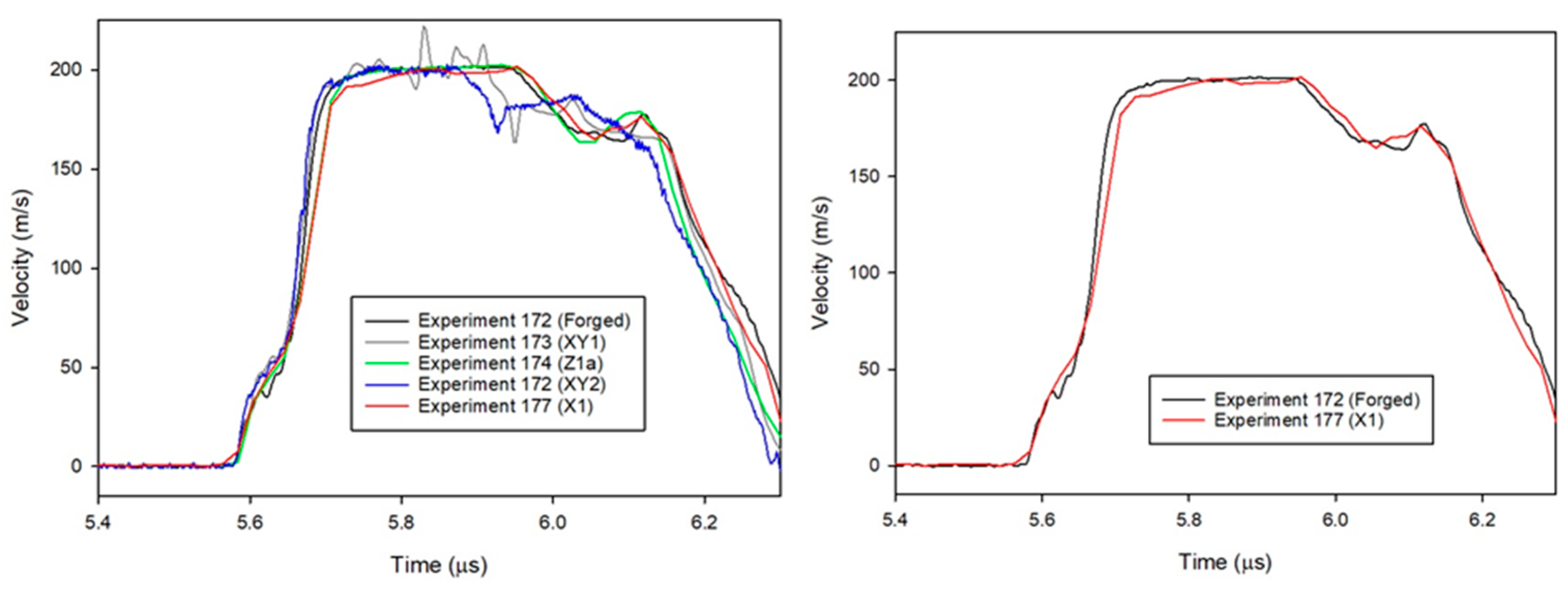
Figure 5 shows velocity-time plots extracted from all experiments, and from experiments 172 (forged 304L) and 177 (AM 304L, X1). The velocimetry curves are plotted such that the elastic waves are aligned in time. This figure shows that the plastic wave arrives earlier in the forged sample because of the higher shock velocity, Us.
Figure 6 shows an example of the wave profile in the quartz baseplate. The time when the shock enters the sample is determined from this type of data. The front of the velocity-time profile, where there is a shape rise in the velocity above the background, marks the time of impact between the quartz impactor and baseplate. The signal then plateaus, which indicates that during this time, the wave is traveling through the baseplate. The sharp drop at the end corresponds to the time at which the wave exits the baseplate; for the current work, this point in time is designated as the timing fiducial.
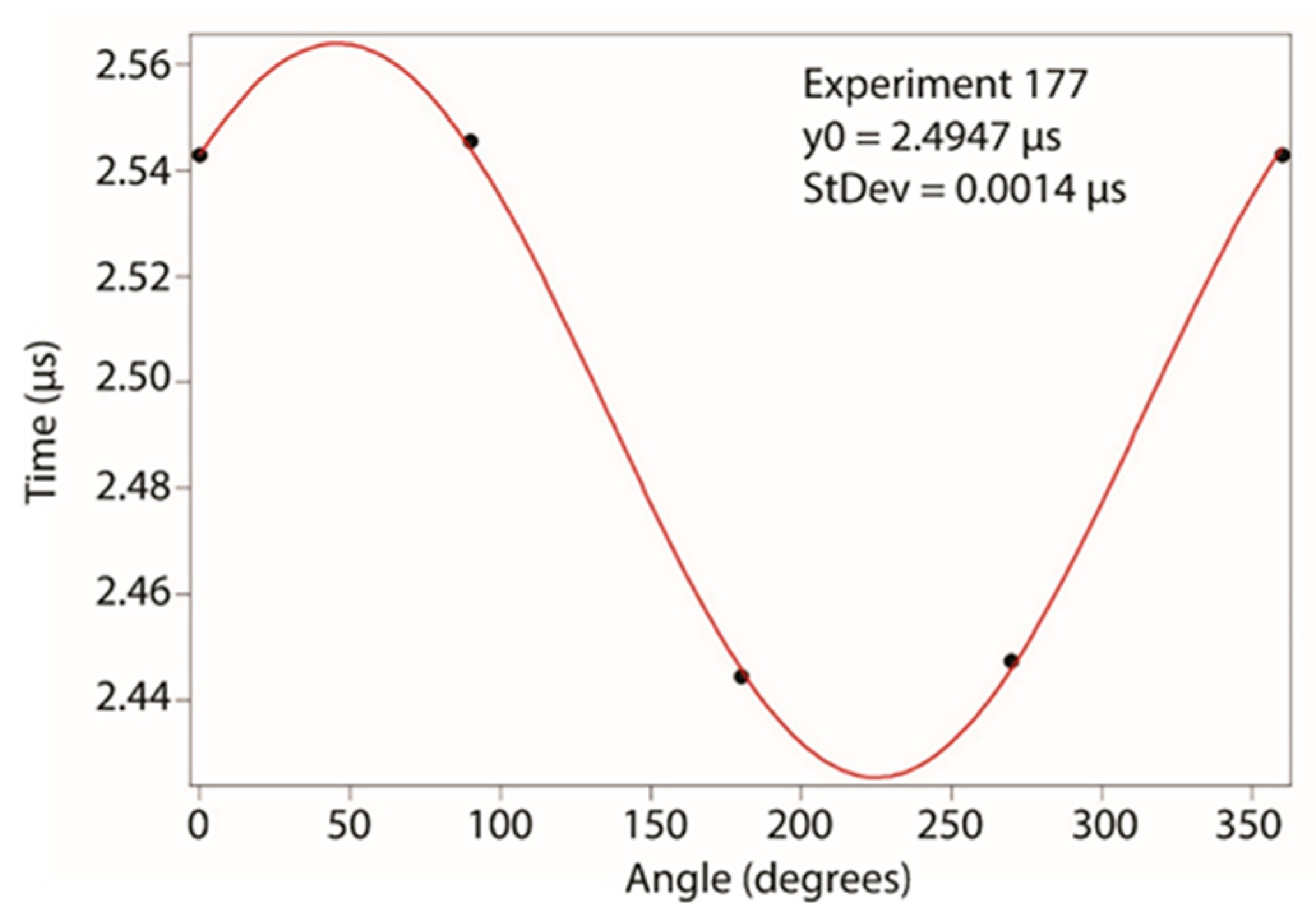
By averaging the exit times from the four probes, the timing associated with when the wave exits the center of the quartz can be determined with an accuracy of 1 to 2 ns. Another way of determining an accurate exit time is to plot the exit times from each of the four probes versus the angle at which the probe sits with respect to the center of the target, then fit those points to a sine wave. The equation for the sine wave is
y = y 0 + A sin ( f x + φ ) ,
where A is the amplitude of the wave, f is the frequency, and φ is the phase. The constant, y0, is the midline of the sine curve and corresponds to the time at which the shock enters the front of the target. An example fit is shown in Figure 7.
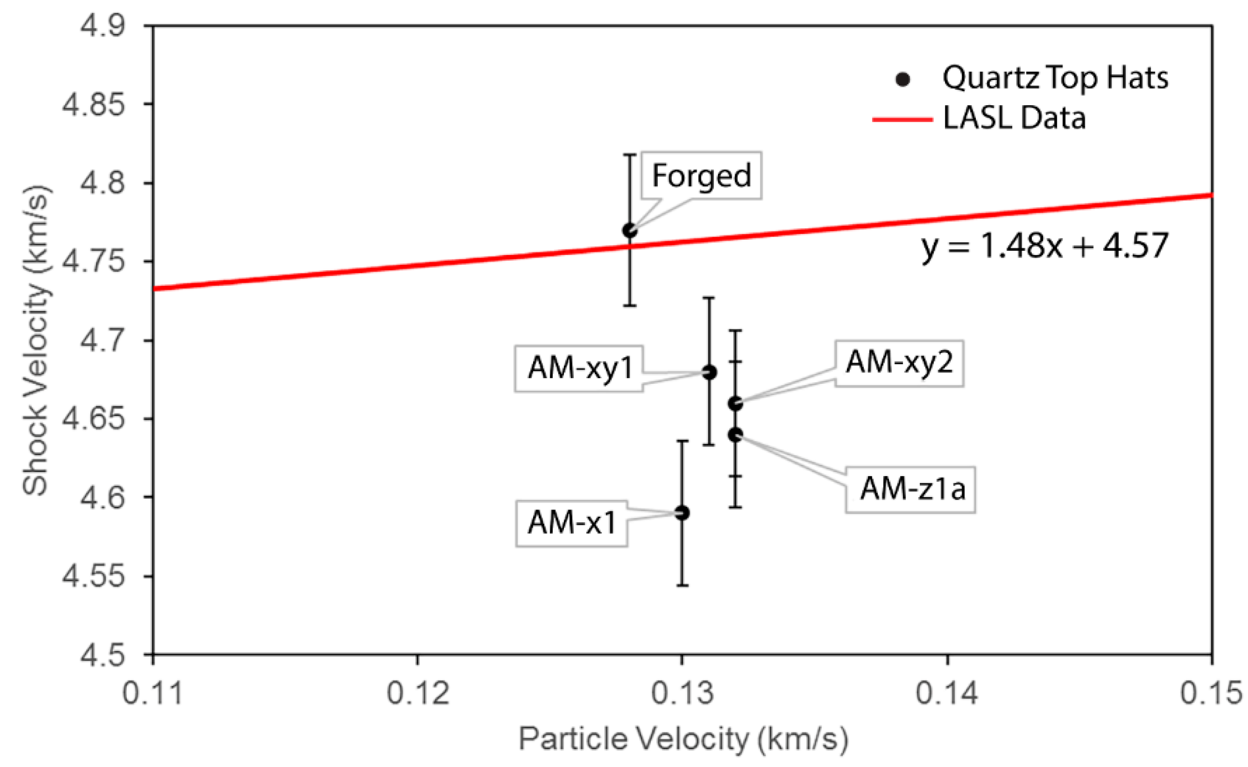
The particle and shock velocities presented in Table 3 are plotted along with the extrapolated shock Hugoniot for 304L SS from work performed at Los Alamos Scientific Laboratory (LASL) [34] and shown in Figure 8. The LASL Shock Hugoniot Data is a compendium of Hugoniot data released by LASL (LANL’s predecessor) in 1980 and is considered a standard reference. The shock velocities in this work were calculated by using the average of the exit times from the quartz baseplate collected by the four PDV probes and subtracting that time from the plastic wave arrivals at the back of the target, then dividing it into the thickness of the target, as shown by
U S = x target t steel t quartz ,
where US is the shock velocity, xtarget is the thickness of the target, and tsteel and tquartz are the times the plastic wave exits the steel target and quartz baseplate, respectively. Particle velocity was calculated using the measured shock speed in the target and the known Hugoniot for quartz to impedance match between the quartz and the steel target [35]. Uncertainties associated with the calculations are estimated to be between 1.0% and 1.5%.
Figure 8 shows that there is a noticeable difference between the AM 304L shock velocities and the data derived from the LASL Hugoniot data [34]. The LASL data, however, does match the shock velocity measured from the forged 304L quite well, lying well within the estimated limits of error. All the AM shock velocities are lower than the forged metal. The error in shock velocities was estimated by using the sum of the squares of the error in determining the travel time of the plastic wave and in measuring the thickness of the samples, such that
Δ U s U s = ( Δ t t ) 2 + ( Δ x x ) 2 ,
where Us is the shock velocity, t is the time, x is the sample thickness, and ΔUs, Δt, and Δx are the errors in those values. The error in determining the travel time was estimated to be from 3 to 4 ns out of ~440 ns and the error in measuring the thickness of the sample to be around 10 μm out of 2000 μm (2 mm). This gives an overall error of less than 1%, with the major contribution to the error coming from determining wave transit times. The relatively long rise time for the plastic (shock) wave because of the relatively low shock stress, in addition to the uncertainty involved in choosing the time of arrival for the midpoint of that rise, contributes significantly to timing uncertainty. The difference between forged 304L result and the value derived from the LASL data for roughly the same particle velocity is around 0.5%, which is within the estimated error bar. The differences between the shock velocities measured from the AM samples and the values obtained from the LASL data range between 1.7% and 3.6%, falling well outside the estimated errors.

4. Discussion

Prior Hugoniot research on type 304L SS [34] established an Us-up Hugoniot that was extrapolated to lower particle velocities as shown in Figure 8. Because of the manufacturing process used in this prior research, these samples were full density, which was reported as 7.903 gm/cm3. However, alloys are composed of solid solution mixtures of several elements, and the precise amounts of these components (chemistry) can vary somewhat, leading to a potential for more scatter in the initial density than is typical for elemental material samples. This means that caution must be applied when comparing alloys used in experiments from different research groups and from different sources. In addition, when alloy samples are manufactured using an AM process, it is possible that small amounts of porosity from the manufacturing process are present. Post processing methods can help to minimize this, but this possibility must be considered. The effect of even relatively small amounts of porosity on shock velocity is known to cause it to be slower than for full density samples. This is due to the mechanics of the dynamic void collapse process, and the resulting increase in thermal energy. In fact, it has been shown by previous research on porous materials that even a 1% drop in density for certain metals can lead to drop in shock velocity of more than 2% [36,37]. This highlights the importance of initial density measurements. As observed in Table 1, the initial densities for samples used in these experiments show no clear trends that are aligned with the differences in measured shock velocities. Based on this data, we conclude that porosity cannot be clearly identified as the factor leading to the measured differences in the shock velocity. Another hypothesis is that the grain size and morphology differences between the AM and the forged samples could be causing a 3% decrease in the shock velocity. However, previous work by Yang et al. [24] on aluminum to investigate the effect of grain size on measured shock velocities has clearly shown that grain size does not alter the shock velocity. Work by Choi et al. [38] on Nickel also shows no measurable differences in the equation of state of single crystal Nickel measured through molecular dynamics and the experimental equation of state from polycrystalline Nickel. However, these studies were performed at particle velocities where the plastic wave was over-driven and as such the material microstructure did not matter. In contrast, the regime of the current experiments is much lower where the measurements exhibit two-wave structure. Systematic experiments where only the grain size is varied in a metal, in the elastic-plastic regime (<600 m/s), would be required to conclusively prove this hypothesis.
Another possibility for the observed variations in shock velocity could be the difference in texture between the AM and wrought materials. This was chosen as a possibility because atomistic simulations using molecular dynamics (MD) have hypothesized an effect of orientation on the shock Hugoniot especially in the particle velocity regimes where materials retain its elastic plastic behavior. MD simulations by Bringa et al. [39] hypothesized that different orientations of single-crystal copper may have different shock Hugoniots in the regime where the material has a two-wave structure. However, Figure 3 clearly shows that texture changes between materials remain minimal and are possibly not the cause of the differences in the shock velocity. It is also important to note that there have been experimental efforts by Chau et al. [25] to measure differences in the shock velocity as a function of orientation in the elastic-plastic regime, although at much higher stress states than in this study. However, these did not show any measurable differences in the shock velocities as a function of orientation. A follow-up experimental study by Thomas et al. [22] at lower pressures was also unable to distinguish any differences using a similar technique to measure shock speeds in copper. Another contributing factor to the observed differences in shock velocity could be the varying dislocation densities in the AM vs. wrought material. Systematic neutron diffraction experiments by Pokharel et al. [40] measured an increased dislocation density in the same AM 304L SS used in this study. This change in dislocation density could alter the equation of state in a measurable manner as shown by Hahn et al. [41] in their molecular dynamics simulations. An increase in dislocation density would also lead to an increase in the Hugoniot Elastic Limit of the AM 304L SS. This is corroborated by Figure 5. In addition, a change in the Hugoniot elastic limit may have the effect of changing the shock velocity. Figure 9a shows shock speed versus particle velocity resulting from solving the Hugoniot jump conditions with a Gruneisen equation-of-state and three different representations of the dynamic strength where the axial stress at the Hugoniot elastic limit (HEL) is 1 GPa. The solution scheme follows that of Luscher et al. [42] which considers an initial jump from ambient to HEL conditions and a second jump from the HEL to the final Hugoniot state along a Rayleigh line. The equation-of-state for all cases is Mie-Gruneisen with parameters from Steinberg [43]. The three different assumptions regarding strength include (i) elastic perfectly plastic (EPP) where the deviatoric stress is maintained at the constant yield stress on the Hugoniot, (ii) no strength, which recovers the equation of state only solution, and (iii) HEL at a specified yield stress and subsequent relaxation so there is no deviatoric stress on the final Hugoniot. The equation of state only solution directly coincides with the linear Us-up fit of Marsh [34], and the EPP solution uniformly increases the shock velocity across all particle velocities in proportion to the constant yield stress. However, the case that considers a jump from the HEL to a final Hugoniot state in which the deviatoric stresses are relaxed to a hydrostatic state leads to a smaller second shock wave speed. Figure 9b shows the variation of wave speed with the strength of the HEL at three different values of particle velocity on the final Hugoniot for the case where secondary wave leads to relaxation of deviatoric stresses to hydrostatic state.
The plot illustrates that the shock velocity is reduced with increasing strength of the HEL, and that this effect is reduced at larger shock magnitudes as characterized by particle velocity on the final Hugoniot.
However, it is important to note that there are many assumptions in this hypothesis and additional work with systematic experiments that alter only the dislocation density through cold work would be required to prove this hypothesis. For this specific work, the change in the shock velocities between AM and forged material could be a combination of many factors such as grain size, morphology and dislocation density. This work clearly demonstrates that it is important to measure equation of state properties of AM materials and the fact that microstructure could play a significant role in determining shock velocities in regimes where the material retains its elastic-plastic behavior.

5. Conclusions

In this work, experiments were carefully performed to measure the shock Hugoniot (relationship between particle and shock velocity) for forged and AM 304L SS. The results from this work showed that the shock velocities in AM 304L were up to 3% lower than its forged counterpart. This difference was determined to be outside the estimated uncertainties for this type of experiment. While the initial hypothesis from this research was that residual porosity due the manufacturing process was the most likely cause of as-measured slow shock velocities, a correlation between initial density and shock velocity was not found. As a result, many alternate hypotheses were pursued related to differences in grain size and morphology, texture and dislocation density to understand the differences in the shock velocities between AM and forged 304L SS. However, due to the complex microstructure of the AM material it was found impossible to separate these three factors from each other. Hence, it was concluded that all three: grain size and morphology, texture and dislocation density may contribute to some extent to alter the shock velocity between AM and forged 304L. An increased dislocation density serves to increase the Hugoniot Elastic Limit in the AM 304L SS and this may cause the shock velocity to decrease. This work highlights that studying equation of state properties of metals with different microstructure and strength properties is a rich area of research that requires additional experiments that allow for changing one feature of the microstructure at a time. This work additionally highlights the importance of re-measuring of AM materials and comparing to results from forged counterparts.

Author Contributions

Conceptualization, R.S.H., G.T.G.III and S.J.F.; methodology, R.S.H., S.A.T.; software, S.A.T.; validation, S.A.T., R.S.H.; formal analysis, S.A.T., R.S.H., D.J.L., R.M.M., M.C.H.; investigation, S.A.T., R.S.H., D.J.L., R.M.M., M.C.H.; resources, R.S.H., G.T.G.III and S.J.F.; data curation, S.A.T., R.S.H., D.J.L., R.M.M.; writing—original draft preparation, S.A.T.; writing—R.S.H., G.T.G.III, D.J.L. and S.J.F.; supervision, R.S.H., G.T.G.III and S.J.F.; project administration, R.S.H., G.T.G.III and S.J.F.; funding acquisition, R.S.H., G.T.G.III and S.J.F. All authors have read and agreed to the published version of the manuscript.

Funding

This work was supported by the (1) US Department of Energy through the Los Alamos National Laboratory. Los Alamos National Laboratory is operated by Triad National Security, LLC, for the National Nuclear Security Administration of U.S. Department of Energy (Contract No. 89233218CNA000001) and (2) Mission Support and Test Services, LLC, under Contract No. DE-NA0003624 with the U.S. Department of Energy, National Nuclear Security Administration.

Data Availability Statement

Data is available upon request from corresponding author.

Acknowledgments

We gratefully acknowledge the support of the NNSS C3 Launcher team, including Jeff Cates, Russ Howe, James Majdanac, Melissa Matthes, and Todd Ware. The United States Government retains and the publisher, by accepting the article for publication, acknowledges that the United States Government retains a non-exclusive, paid-up, irrevocable, worldwide license to publish or reproduce the published form of this manuscript, or allow others to do so, for United States Government purposes. The U.S. Department of Energy will provide public access to these results of federally sponsored research in accordance with the DOE Public Access Plan (http://energy.gov/downloads/doe-public-access-plan, accessed on 25 September 2022). The views expressed in the article do not necessarily represent the views of the U.S. Department of Energy or the United States Government.

Conflicts of Interest

The authors declare no conflict of interest.

References

  1. Lewandowski, J.J.; Seifi, M. Metal Additive Manufacturing: A Review of Mechanical Properties. Annu. Rev. Mater. Sci. 2016, 46, 151–186. [Google Scholar] [CrossRef] [Green Version]
  2. Gorsse, S.; Hutchinson, C.; Gouné, M.; Banerjee, R. Additive manufacturing of metals: A brief review of the characteristic microstructures and properties of steels, Ti-6Al-4V and high-entropy alloys. Sci. Technol. Adv. Mater. 2017, 18, 584–610. [Google Scholar] [CrossRef] [PubMed] [Green Version]
  3. Bajaj, P.; Hariharan, A.; Kini, A.; Kürnsteiner, P.; Raabe, D.; Jägle, E.A. Steels in additive manufacturing: A review of their microstructure and properties. Mater. Sci. Eng. A 2020, 772, 138633. [Google Scholar] [CrossRef]
  4. Vora, J.J.; Badheka, V.J. Experimental investigation on microstructure and mechanical properties of activated TIG welded reduced activation ferritic/martensitic steel joints. J. Manuf. Process. 2017, 25, 85–93. [Google Scholar] [CrossRef]
  5. Laurençon, M.; de Rességuier, T.; Loison, D.; Baillargeat, J.; Domfang Ngnekou, J.N.; Nadot, Y. Effects of additive manufacturing on the dynamic response of AlSi10Mg to laser shock loading. Mater. Sci. Eng. A 2019, 748, 407–417. [Google Scholar] [CrossRef]
  6. Jones, D.R.; Fensin, S.J.; Dippo, O.; Beal, R.A.; Livescu, V.; Martinez, D.T.; Trujillo, C.P.; Florando, J.N.; Kumar, M.; Gray, G.T. Spall fracture in additive manufactured Ti-6Al-4V. J. Appl. Phys. 2016, 120, 135902. [Google Scholar] [CrossRef]
  7. Jones, D.R.; Fensin, S.J.; Ndefru, B.G.; Martinez, D.T.; Trujillo, C.P.; GrayIII, G.T. Spall fracture in additive manufactured tantalum. J. Appl. Phys. 2018, 124, 225902. [Google Scholar] [CrossRef]
  8. Gray, G., III; Livescu, V.; Rigg, P.; Trujillo, C.; Cady, C.; Chen, S.; Carpenter, J.; Lienert, T.; Fensin, S. Structure/property (constitutive and spallation response) of additively manufactured 316L stainless steel. Acta Mater. 2017, 138, 140–149. [Google Scholar] [CrossRef]
  9. Wise, J.L.; Adams, D.P.; Nishida, E.E.; Song, B.; Maguire, M.C.; Carroll, J.; Reedlunn, B.; Bishop, J.E.; Palmer, T.A. Comparative shock response of additively manufactured versus conventionally wrought 304L stainless steel. AIP Conf. Proc. 2017, 1793, 100015. [Google Scholar] [CrossRef] [Green Version]
  10. Yasa, E.; Deckers, J.; Kruth, J.-P.; Rombouts, M.; Luyten, J. Charpy impact testing of metallic selective laser melting parts. Virtual Phys. Prototyp. 2010, 5, 89–98. [Google Scholar] [CrossRef]
  11. Zhang, B.; Dembinski, L.; Coddet, C. The study of the laser parameters and environment variables effect on mechanical properties of high compact parts elaborated by selective laser melting 316L powder. Mater. Sci. Eng. A 2013, 584, 21–31. [Google Scholar] [CrossRef]
  12. Verlee, B.; Dormal, T.; Lecomte-Beckers, J. Density and porosity control of sintered 316L stainless steel parts produced by additive manufacturing. Powder Met. 2012, 55, 260–267. [Google Scholar] [CrossRef]
  13. Cherry, J.A.; Davies, H.M.; Mehmood, S.; Lavery, N.P.; Brown, S.G.R.; Sienz, J. Investigation into the effect of process parameters on microstructural and physical properties of 316L stainless steel parts by selective laser melting. Int. J. Adv. Manuf. Technol. 2015, 76, 869–879. [Google Scholar] [CrossRef] [Green Version]
  14. Wu, A.S.; Brown, D.W.; Kumar, M.; Gallegos, G.F.; King, W.E. An Experimental Investigation into Additive Manufacturing-Induced Residual Stresses in 316L Stainless Steel. Met. Mater. Trans. A 2014, 45, 6260–6270. [Google Scholar] [CrossRef]
  15. Carlton, H.D.; Haboub, A.; Gallegos, G.F.; Parkinson, D.Y.; MacDowell, A.A. Damage evolution and failure mechanisms in additively manufactured stainless steel. Mater. Sci. Eng. A 2016, 651, 406–414. [Google Scholar] [CrossRef] [Green Version]
  16. Yadollahi, A.; Shamsaei, N.; Hammi, Y.; Horstemeyer, M.F. Quantification of tensile damage evolution in additive manufactured austenitic stainless steels. Mater. Sci. Eng. A 2016, 657, 399–405. [Google Scholar] [CrossRef]
  17. Röttger, A.; Geenen, K.; Windmann, M.; Binner, F.; Theisen, W. Comparison of microstructure and mechanical properties of 316 L austenitic steel processed by selective laser melting with hot-isostatic pressed and cast material. Mater. Sci. Eng. A 2016, 678, 365–376. [Google Scholar] [CrossRef]
  18. Agrawal, A.K.; de Bellefon, G.M.; Thoma, D. High-throughput experimentation for microstructural design in additively manufactured 316L stainless steel. Mater. Sci. Eng. A 2020, 793, 139841. [Google Scholar] [CrossRef]
  19. Rankouhi, B.; Agrawal, A.K.; Pfefferkorn, F.E.; Thoma, D.J. A dimensionless number for predicting universal processing parameter boundaries in metal powder bed additive manufacturing. Manuf. Lett. 2020, 27, 13–17. [Google Scholar] [CrossRef]
  20. Simonelli, M.; Tse, Y.Y.; Tuck, C. Effect of the build orientation on the mechanical properties and fracture modes of SLM Ti-6A1-4V. Mater. Sci. Eng. A 2014, 616, 1–11. [Google Scholar] [CrossRef]
  21. Pace, M.; Guarnaccio, A.; Dolce, P.; Mollica, D.; Parisi, G.; Lettino, A.; Medici, L.; Summa, V.; Ciancio, R.; Santagata, A. 3D additive manufactured 316L components microstructural features and changes induced by working life cycles. Appl. Surf. Sci. 2017, 418, 437–445. [Google Scholar] [CrossRef]
  22. Thomas, S.A.; Hixson, R.S.; Hawkins, M.C.; Strand, O.T. Wave speeds in single-crystal and polycrystalline copper. Int. J. Impact Eng. 2020, 139, 103506. [Google Scholar] [CrossRef]
  23. Fadida, R.; Rittel, D.; Shirizly, A. Dynamic Mechanical Behavior of Additively Manufactured Ti6Al4V With Controlled Voids. J. Appl. Mech. 2015, 82, 041004. [Google Scholar] [CrossRef]
  24. Yang, X.; Zeng, X.; Pu, C.; Chen, W.; Chen, H.; Wang, F. Molecular dynamics modeling of the Hugoniot states of aluminum. AIP Adv. 2018, 8, 105212. [Google Scholar] [CrossRef] [Green Version]
  25. Chau, R.; Stölken, J.; Asoka-Kumar, P.; Kumar, M.; Holmes, N.C. Shock Hugoniot of single crystal copper. J. Appl. Phys. 2010, 107, 023506. [Google Scholar] [CrossRef] [Green Version]
  26. Morrow, B.M.; Lienert, T.J.; Knapp, C.M.; Sutton, J.O.; Brand, M.J.; Pacheco, R.M.; Livescu, V.; Carpenter, J.S.; Gray, G.T. Impact of Defects in Powder Feedstock Materials on Microstructure of 304L and 316L Stainless Steel Produced by Additive Manufacturing. Met. Mater. Trans. A 2018, 49, 3637–3650. [Google Scholar] [CrossRef]
  27. Mataya, M.; Carr, M.; Krenzer, R.; Krauss, G. Processing and Structure of High-Energy-Rate-Forged 21-6-9 and 304L Forgings; Rockwell International Corp.: Golden, CO, USA, 1981. [Google Scholar] [CrossRef] [Green Version]
  28. Wright, S.I.; Adams, B.L.; Kunze, K. Application of a new automatic lattice orientation measurement technique to polycrystalline aluminum. Mater. Sci. Eng. A 1993, 160, 229–240. [Google Scholar] [CrossRef]
  29. Spierings, A.B.; Schneider, M.; Eggenberger, R. Comparison of density measurement techniques for additive manufactured metallic parts. Rapid Prototyp. J. 2011, 17, 380–386. [Google Scholar] [CrossRef]
  30. Arvieu, C.; Galy, C.; Le Guen, E.; Lacoste, E. Relative Density of SLM-Produced Aluminum Alloy Parts: Interpretation of Results. J. Manuf. Mater. Process. 2020, 4, 83. [Google Scholar] [CrossRef]
  31. Bai, S.; Perevoshchikova, N.; Sha, Y.; Wu, X. The Effects of Selective Laser Melting Process Parameters on Relative Density of the AlSi10Mg Parts and Suitable Procedures of the Archimedes Method. Appl. Sci. 2019, 9, 583. [Google Scholar] [CrossRef] [Green Version]
  32. Strand, O.T.; Goosman, D.R.; Martinez, C.C.; Whitworth, T.L.; Kuhlow, W.W. Compact system for high-speed velocimetry using heterodyne techniques. Rev. Sci. Instrum. 2006, 77, 083108. [Google Scholar] [CrossRef]
  33. Mitchell, A.C.; Nellis, W.J. Shock compression of aluminum, copper, and tantalum. J. Appl. Phys. 1981, 52, 3363–3374. [Google Scholar] [CrossRef]
  34. Marsh, S.P. (Ed.) LASL Shock Hugoniot Data; University of California Press: Berkeley, CA, USA, 1980. [Google Scholar]
  35. Forbes, J.W. Impedance Matching Technique. In Shock Wave Compression of Condensed Matter; Springer: Berlin/Heidelberg, Germany, 2012; pp. 31–57. [Google Scholar]
  36. Mcqueen, R.; Marsh, S.; Taylor, J.; Fritz, J.N.; Carter, W. The equation of state of solids from shock wave studies. In High Velocity Impact Phenomena; Kinslow, R., Ed.; Academic Press: Cambridge, MA, USA, 1970; pp. 293–417. [Google Scholar]
  37. Trunin, R.F. Shock Compression of Condensed Materials; Cambridge University Press: Cambridge, UK, 1998. [Google Scholar]
  38. Choi, J.; Yoo, S.; Song, S.; Park, J.S.; Kang, K. Molecular dynamics study of Hugoniot relation in shocked nickel single crystal. J. Mech. Sci. Technol. 2018, 32, 3273–3281. [Google Scholar] [CrossRef]
  39. Bringa, E.M.; Cazamias, J.U.; Erhart, P.; Stölken, J.; Tanushev, N.; Wirth, B.D.; Rudd, R.E.; Caturla, M.J. Atomistic shock Hugoniot simulation of single-crystal copper. J. Appl. Phys. 2004, 96, 3793–3799. [Google Scholar] [CrossRef] [Green Version]
  40. Pokharel, R.; Patra, A.; Brown, D.W.; Clausen, B.; Vogel, S.C.; Gray, G.T. An analysis of phase stresses in additively manufactured 304L stainless steel using neutron diffraction measurements and crystal plasticity finite element simulations. Int. J. Plast. 2019, 121, 201–217. [Google Scholar] [CrossRef]
  41. Hahn, E.N.; Fensin, S.J. Influence of defects on the shock Hugoniot of tantalum. J. Appl. Phys. 2019, 125, 215902. [Google Scholar] [CrossRef]
  42. Luscher, D.J.; Cawkwell, M.J.; Ramos, K.J.; Sandberg, R.L.; Bolme, C.A. Interpreting Experimental Results from Shock Impacts on Single Crystal PETN in the Context of Continuum Models. Propellants Explos. Pyrotech. 2019, 45, 284–294. [Google Scholar] [CrossRef]
  43. Steinberg, D.J. Equation of State and Strength Properties of Selected Materials; Lawrence Livermore National Laboratory: Livermore, CA, USA, 1996. [Google Scholar]
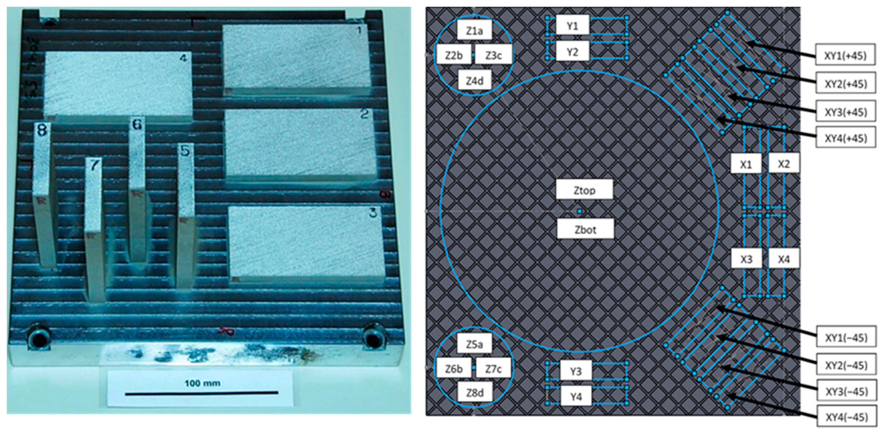
Figure 1. (left) Optical photograph of EOS builds on 304L SS baseplate. (right) Schematic of plate 2 and locations from which samples were obtained for dynamic experiments.
Metals 12 01661 g001
Figure 2. EBSD micrographs for (a) AM 304L XY3 +45, (b) AM 304L XY4 +45, (c) AM 304L Z6B, (d) AM 304L Z7C, and (e) forged 304L SS.
Metals 12 01661 g002
Figure 3. Texture associated with (a) AM 304L XY3 +45, (b) AM 304L XY4 +45, (c) AM 304L Z6B, (d) AM 304L Z7C, and (e) forged material.
Metals 12 01661 g003
Figure 4. Quartz top-hat experimental design. The projectile and target plates are shown in gray. Affixed to the front of the projectile is the syntactic foam backing (orange) and the quartz impactor (purple). The target is centered on the target plate and is comprised of a quartz baseplate (purple), the 304L sample (blue), and a sapphire window (yellow). A single collimating probe measures the projectile velocity. There are two 2-fiber probes in the center, one slightly offset from the center of the target, and four additional 2-fiber probes that circle the quartz baseplate at a fixed radius (11.25 mm). The design also includes a single piezoelectric pin (green) that serves as a diagnostics trigger.
Metals 12 01661 g004
Figure 5. Velocity-time plot from (left) experiments 172 (forged 304L) and 173 (AM XY1), 174 (Z1a), 172 (XY2) and 177 (AM X1) with aligned elastic waves. (right) Velocity-time plot for experiments 172 (forged) and 177 (AM X1) highlighting differences between forged and AM 304L SS.
Metals 12 01661 g005
Figure 6. Velocity-time profile in the quartz baseplate. The sharp rise in the velocity occurs when the shock wave enters the quartz baseplate, and the sharp drop in the velocity allows us to determine accurately when the shock leaves the baseplate and enters the target sample. The drop is sharp enough to allow timing to be determined within 1–3 ns.
Metals 12 01661 g006
Figure 7. Sine fit of the exit times taken from the outer probes for experiment 177.
Metals 12 01661 g007
Figure 8. Shock velocity as a function of particle velocity also known as the Hugoniot equation of state from quartz top-hat experiments with 1% error bars plotted over the extrapolated shock Hugoniot for 304L SS from the LASL Shock Hugoniot Data [34].
Metals 12 01661 g008
Figure 9. (a) Wave speed versus particle velocity computed using EPP, equation of state only, and initial yield followed by relaxation to pure hydrostatic Hugoniot state (relax). (b) Illustration of the decrease in plastic wave speed with increasing magnitude of HEL at fixed values of particle velocity for the case where secondary wave leads to relaxation of deviatoric stresses to hydrostatic state.
Metals 12 01661 g009
Table 1. The measured chemical composition of the 304L SS wrought plate, powder used in the AM process and the as build AM plate in weight percent.
MaterialCSiMnPSCrNiMoCuNOFe
Wrought0.0150.571.470.0190.00218.4710.020.110.180.05<0.01Bal
AM Powder0.0150.531.50.0120.00318.49.80.00.00.050.019Bal
AM Plate0.0200.631.430.0070.00418.3210.030.0150.0080.050.03Bal
Table 2. Measured thicknesses, densities, and longitudinal and shear sound speeds of.
ExperimentMaterialThickness
(mm)
Density
(g/cm3)
Sound Speed
(km/s)
LongitudinalShear
172Forged2.010 ± 0.0107.86 ± 0.035.78 ± 0.083.15 ± 0.06
173AM-XY11.997 ± 0.0107.87 ± 0.035.77 ± 0.083.10 ± 0.06
174AM-Z1a1.999 ± 0.0107.87 ± 0.035.72 ± 0.083.20 ± 0.06
176AM-XY22.001 ± 0.0107.90 ± 0.035.80 ± 0.083.12 ± 0.06
177AM-X11.996 ± 0.0107.83 ± 0.035.80 ± 0.083.16 ± 0.06
Table 3. Impactor velocity (UD), particle velocity (up), and shock velocity (US) measurements from the quartz top-hat experiments.
Experiment MaterialVelocity
(km/s)
Impactor, UDParticle, upShock, Us
172Forged0.399 ± 0.0030.128 ± 0.0024.77 ± 0.05
173AM-XY10.400 ± 0.0030.131 ± 0.0024.68 ± 0.05
174AM-Z1a0.400 ± 0.0030.132 ± 0.0024.64 ± 0.05
176AM-XY20.400 ± 0.0030.132 ± 0.0024.66 ± 0.05
177AM-X10.395 ± 0.0030.130 ± 0.0024.59 ± 0.05
Publisher’s Note: MDPI stays neutral with regard to jurisdictional claims in published maps and institutional affiliations.