Abstract
This paper reviews the role of void nucleation, growth, and coalescence on the spall failure process in light metals. Based on the review of the open literature, the preponderance of evidence show that void nucleation, growth, and coalescence are prevalent in light metals such as HCP magnesium and FCC aluminum alloys. The as-received microstructure and its evolution play a crucial role on how voids nucleate, grow, and coalesce. Nucleation of voids in these light metals and metallic alloys can be either homogeneous and heterogeneous but at high enough stresses, both homogeneous and heterogeneous nucleation can be activated simultaneously. Secondary phase particles and intermetallics can strongly influence spall failure, through matrix-precipitate/intermetallic debonding or precipitate/intermetallic cracking during shock compression. Studying spall failure through modeling has proven to be an invaluable tool in developing a fundamental understanding of void nucleation, growth, coalescence, and consequent spall failure. However, since new alloys are currently been developed, more experimental and modeling research are needed to further understand how spall failure initiate and grow in these new alloys.
1. Introduction
Spallation is ubiquitous in solid materials during high velocity impact events. To defeat spall failure, it is necessary to develop a fundamental understanding of the underlying mechanisms active during the failure process. Spallation is a consequence of two rarefaction or decompression waves colliding in a material. This collision generally creates a tensile region in the material and if the tensile stresses are large enough, voids are nucleated, which then grow and coalesce to cause spall failure. The process of void nucleation, growth, and coalescence is prevalent in metals and metallic alloys. However, the dominant failure mechanism in brittle materials such as ceramics is microcrack nucleation, growth, and coalescence. Spall failure in terms of strength is strongly dependent on several parameters of state but peak shock stress, pulse duration, and unloading strain-rate are the three main parameters that can significantly affect spall strength. Because of this strong dependency on several parameters of state, spall strength is not considered to be an intrinsic material property. For metals and metallic alloys, the unloading strain-rates usually observed using gas and powder guns prior to spallation ranges from 10 s to 10 s [1] but can be higher using explosives and laser devices.
Hopkinson [2] made the first observation of spall failure in their research in 1914, and numerous researchers have since investigated the phenomenon in metals and metallic alloys [3,4,5,6,7,8,9,10,11,12,13,14,15,16]. Early spall studies proved that spallation is an evolutionary process whereby a material completely fails due to the nucleation and growth of voids or microfractures [17]. Developing a criterion for describing the spall failure process was one of the initial goals for researchers. The first criterion was based on the idea that spallation occurred when a material’s distinctive critical tensile stress was attained [2]. The slow growth of damage in shock-loaded materials was later explained by Skidmore [18] and Breed et al. [19] using the stress rate or stress gradient criterion. A short while later, Tuler and Butcher [20] devised a cumulative damage criterion to investigate the temporal dependency of spall fracture. In addition, Tobolsky and Eyring [21] and Zhurkov [22] established the idea of damage as a rate process obeying the Arrhenius rate equations for bond breakage and repair. Curran and colleagues [23] used empirical constitutive relationships developed from comprehensive structure-property relationships to provide a versatile method for analyzing the nucleation and growth (NAG) of voids in metals. The majority of these criteria call for experimental parameters that must typically be gathered from carefully designed shock experiments in order to characterize specific materials. To examine the spall response of a variety of condensed matter, numerous experimental methods and diagnostic tools have been developed over the years [24,25,26,27,28,29].
A material’s spall response can be explored at length scales ranging from nanometers to millimeters and time scales ranging from nanoseconds to microseconds. The plate impact experiment is the most widely used approach for investigating a material’s spall response. They are often carried out with the use of gas or powder guns, explosives, electro-explosives (electric guns), and radiation devices (lasers). Plate impact experiments allow for near real-time measurement of velocity or stress waveforms, as well as the recovery of the shocked sample for metallurgical examination at the end-state. The augmentation of velocity or stress wave histories, as well as microstructural information generated from metallurgical assessments, has proven to be particularly useful in understanding the spall response and failure characteristics of a variety of materials [30,31,32,33,34,35,36,37,38]. Table 1 is a compilation of spall strengths for various magnesium and aluminum systems with their corresponding densities, sound speeds, and peak shock stresses. The table clearly reveals that the spall strengths of magnesium and aluminum systems are comparable, although aluminum exhibits a slightly higher average value. However, single crystal magnesium shocked along the hard -axis exhibited the highest spall strength. The reader should note that some of the spall strength values listed in Table 1 are corrected for elastic-plastic effects while others are not.

Table 1.
Spall strength data of selected magnesium and aluminum systems. , , , , and are density, longitudinal sound speed, bulk sound speed, peak shock stress, and spall strength, respectively.
Gas and powder guns are often used to conduct plate impact experiments because they offer experimentalists the most control over repeatability with regards to impact velocity; they are relatively safe and straight forward to operate. They require that a flyer plate (impactor) mounted on a sabot be driven into a target plate (sample), as indicated in the Lagrangian diagram in Figure 1a. As shown in Figure 1b, velocimetry (Velocity Interferometer for Any Reflector (VISAR) or Photon Doppler Velocimetry (PDV)) is used to acquire and assess the free surface/particle velocity history of the target in near real-time. The impact velocity is obtained through electrical shorting pins or lasers. Both the flyer and target plates develop a state of uniaxial strain (i.e., lateral strains are zero) upon impact. The flyer and target free surfaces reflect two sets of elastic and plastic (shock) waves going in the opposite direction as release or rarefaction waves in elastic-plastic materials (see Figure 1a). A tensile region is developed in the target material when both release or rarefaction waves collide (note that for spall experiments, the target is always thicker than the flyer). If the tensile stresses developed are higher than the threshold for void nucleation, growth, and coalescence, the metal or metallic alloy will fail by spallation. This failure process occurring within the target material is interrogated at the free surface using VISAR or PDV velocimetry techniques; the velocity-time history is recorded as shown in Figure 1b and then analyzed to extract the pullback velocity for spall strength determination, Hugoniot Elastic Limit (HEL), and other pertinent parameters such as strain-rate (loading and unloading). Numerous technical papers and reviews of the plate impact technique are available in the open literature [1,39].
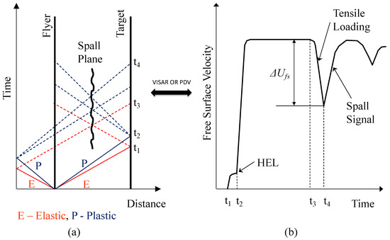
Figure 1.
(a) A simplified Lagrangian (x-t) diagram describing a plate impact event and (b) the resulting breakout free surface velocity profile representation of the spall process.
The primary objective of this paper is to elucidate the role of void nucleation, growth, and coalescence on the spall failure process in light metals such as magnesium and aluminum. A concise historical background with regards to spall failure is first provided, then the active deformation mechanisms in plastically deformed magnesium and aluminum is provided. The active spall failure processes in metals and metallic alloys are described in terms of damage nucleation, growth, and coalescence, then a quantitative background is provided to aid the reader in understanding how damage initiate, develop, and progress to consequent failure. Finally, the microstructural aspects of spall failure in both magnesium and aluminum are discussed.
2. Materials
Light metals such as magnesium and aluminum alloys have long been sought for ballistic applications and numerous other high strain-rate phenomena primarily because of their high strength-to-weight ratio and potential for further improvements in strength and ductility [45,46]. Between the 1950s and 1960s, a concerted effort was devoted to developing new aluminum alloys such as AA5083 and AA7075 for armor applications. Both aluminum alloys are now ubiquitous in armor applications. Currently, a large research effort has been devoted to developing novel severe plastic deformation processing techniques and new magnesium alloys for use in ballistic and numerous high strain-rate applications. The results derived from these research efforts are promising [47,48,49].
2.1. Deformation Mechanisms in Magnesium
A large body of research describing the mechanical behavior of magnesium (Mg) and its alloys at low to intermediate strain rates has revealed that dislocation slip and mechanical twinning are the two dominant deformation mechanisms for accomodating plasticity [50,51,52,53,54,55,56]. When magnesium is plastically deformed, the slip systems that are activated in its hexagonal closed packed crystal lattice structure strongly depend on the loading direction with respect to the crystallographic orientation and the temperature at which the material is deformed [57,58,59,60,61,62]. When plastically deformed, there are three possible dislocation Burgers vectors which can be operative on different slip planes. The first is the basal slip and the Burgers vector equals on the basal slip plane [52,63]. The second is the prismatic slip and the Burgers vector equals or on the slip plane [52,59,64]. The third is the pyramidal slip and the Burgers vector equals on the slip planes and/or [52,65]. It has been reported that the critical resolved shear stress (CRSS) for basal slip with dislocation in magnesium is approximately 0.5 MPa [50], whereas the CRSS for prismatic and pyramidal dislocations is one to two orders of magnitude higher [50,64,66]. The number of easy slip systems in Mg is restricted in comparison to their face and body centered cubic lattice counterparts; hence, during plastic deformation, twinning is critical in accommodating the c-axis strain [56,67]. extension twinning is the dominant mode in Mg and contraction twins can be triggered at high stresses close to fracture [68,69,70,71]. Even though the mechanical behavior of Mg and Mg alloys at low to moderate strain rates cannot be directly linked to that of those shock-compressed, there are some salient similarities between the two. Therefore, the knowledge derived from low to moderate strain rates experiments can provide some insights for studying the deformation mechanisms active under shock compression. As an example, when Mg is compressed along the axis extension twins are activated at all strain rates [51,72,73]; however, when compressed along the axis, contraction twins are activated at low to intermediate strain rates [74] and shock compression [75] if the stress is high enough. As grain size decreases, twinning becomes increasingly difficult but is prevalent at high strain rates [76]. Nevertheless, significant extension twinning has been observed in ultrafine-grained (UFG) Mg samples at dynamic strain rates [72,77,78].
2.2. Deformation Mechanisms in Aluminum
The plastic deformation of face centered cubic (FCC) lattice materials, including aluminum and its alloys, is likely the most characterized of all light metals in the open literature. Numerous studies and descriptions of the microstructural evolution of FCC metals and their alloys during plastic deformation have been explored by researchers and their findings are published in the open literature [79,80,81,82,83,84,85,86]. The face centered cubic (FCC) lattice structure results in a primary slip system. This suggests that aluminum has a family of close-packed planes and close-packed directions, resulting in 12 different close-packed slip systems. There are 4 close-packed planes per unit cell and 3 close-packed directions per plane; therefore, high dislocation density, rapid hardening evolution, and development of dislocation patterning or substructure are expected during plastic deformation. The stacking fault energy (SFE) of aluminum and its alloys is considerably high, ranging from 166 to 200 mJ/m. The deformation properties of FCC metals and metallic alloys such as aluminum are significantly influenced by the SFE. It affects crucial phenomena like a dislocation’s capacity for cross-slipping, the development of partial dislocations, and the formation of twin boundaries (typically undetectable in coarse-grained aluminum), all of which can significantly affect yield behavior [87,88,89].
A structure consisting of cells and subgrains typically develops from dislocation tangles when FCC materials with medium to high stacking fault energy are plastically deformed. In response to both their applied stress and self-stress, these dislocations rearrange themselves into a cellular pattern. According to Hughes [90], there are two sizes at which grain subdivision can take place. The smaller subdivision is made up of incidental dislocation boundaries (IDBs), which are small lattice rotations caused by the statistical mutual trapping of glide dislocations and are frequently supplemented by forest dislocations [91]. The larger subdivision, however, consists of misoriented cell blocks (CBs) that are surrounded by geometrically necessary boundaries (GNBs) that have greater misorientations. These significant misorientations result from lattice mismatches between the different regions formed by the grain subdivision. Microbands (MBs), dense dislocation walls (DDWs), lamellar, and subgrain boundaries are all components of GNBs. The basis for controlling a number of material properties, such as recrystallization and crystallographic texture, are these dislocation structures in conjunction with crystal orientations, which in turn control the plastic response of metals and solid solution alloys with moderate to high stacking fault energies [90].
3. Spall Failure in Metals and Metallic Alloys
Spallation is the most common type of failure during high impact velocity events. It is the separation of a material as a result of the rapid application of a tensile stress and often entails the nucleation, growth, and coalescence of nanoscale or microscale voids, which as a consequence may lead to macroscopic material failure by separation. The spall process occurs quite often in ductile materials. For instance, Curran et al. [23] have demonstrated that void nucleation typically starts at a low tensile stress level (incipient spall) and is influenced by the substructure, microstructure, mechanical and material properties, and tensile loading history of the material in question. Prior to tensile loading, the material initially experiences shock compression, which might alter the material’s as-received substructure and microstructure, which makes the spall process more challenging. Large quantities of defects, such as dislocations, deformation twins, stacking faults, etc., may be introduced into the material depending on the magnitude of the shock stress prior to the tensile load or spall pulse [92,93,94].
The amount of point defects, such as vacancies, vacancy clusters, and interstitials, which are predominantly caused by the non-conservative motion of jogs, might also rise as a result of shock compression [95]. According to Kressel and Brown [95], vacancy clusters can be potential void nucleation sites. Preceding tensile loading, there may be more potential void nucleation sites, which might accelerate spallation and therefore, reduce the spall strength of the material. In addition, prior to tensile unloading, various competing mechanisms, including temperature rise, substructure evolution, dislocation formation, dislocation annihilation, generation of potential void nucleation sites, and microstructure evolution, may have a significant impact on a material’s spall strength. Thus, it is anticipated that a material’s spall strength will be strongly influenced by the peak shock stress, pulse duration, initial temperature, tensile unloading rate, and initial microstructure [7,11,12,38,96,97,98,99,100,101,102,103,104]. However, a survey of the open literature reveals contradictory findings on the dependence of spall strength on peak shock stress [12,96,105], highlighting the complexity of spallation. On the other-hand, to elucidate the importance of parameters such as strain-rate on spall strength, Figure 2 and Figure 3 are provided for magnesium and aluminum systems, respectively. For magnesium systems, the trend is obvious. The spall strength increases with increase in tensile strain-rate. However, for the aluminum systems, the spall strength increases as a function of tensile strain-rate but with significant scatter in the data. For more insights on the effects of tensile strain-rate on spall strength for both magnesium and aluminum, the reader is referenced to Mallick et al. [47] and Moshe et al. [8].
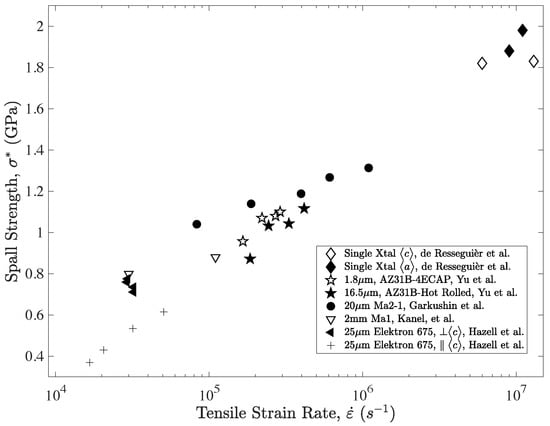
Figure 2.
Spall strength as a function of tensile strain-rate determined from time-resolved velocimetry measurements on pure and alloyed Mg from the open literature. Reproduced or adapted from [41,107,108,109,110].
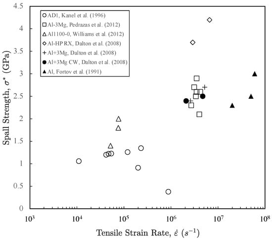
Figure 3.
Spall strength as a function of tensile strain-rate determined from time-resolved velocimetry measurements on pure and alloyed Al from the open literature. Reproduced or adapted from [10,11,111,112,113].
The nucleation of voids in ductile metals is often categorized as homogeneous or heterogeneous [31,32,37,106]. Homogeneous nucleation of voids emanate from submicron heterogeneities such dislocation tangles and networks, low angle grain boundaries, and small impurities. Heterogeneous nucleation of voids emanate from larger than submicron heterogeneities like inclusions and second-phase particles. Because higher stresses are required for homogeneous void nucleation than for heterogeneous nucleation, heterogeneities like second-phase particles are favorable void nucleation sites. However, simultaneous activation of homogeneous and heterogeneous nucleation is possible if the stress is high enough. The nucleated voids then grow and coalesce to form macrocracks, which consequently cause failure of the material.
Numerous investigations have demonstrated that the fracture surface and cross-sections of shock recovered samples reveal that micron and submicron-sized precipitates were responsible for the initiation of spall failure, supporting homogeneous and heterogeneous nucleation of voids [1,35,38,103,107,111,114,115,116,117,118]. There are three strong arguments in favor of this to occur; (1) The creation of potential void nucleation sites through matrix-precipitate debonding or precipitate cracking during the shock compression phase might result from changes in density across the matrix-precipitate interface, i.e., impedance mismatch (2) larger particles in conventional alloys, as particles larger than 100 nm often have interfaces with the matrix that are mechanically weaker than totally coherent ones, (3) reinforcing/strengthening secondary phases that are typically harder; common examples are stoichiometric compounds like ceramics and intermetallic phases. These substances are more brittle than the host matrix around them and are prone to fragment or cleave under shock compression. All three of the aforementioned factors, taken together, have the potential to substantially compromise the shock-compressed material’s structural integrity prior to the arrival of the spall pulse and, as a result, lower the material’s spall strength. It is important to note that a recent investigation on a nanocrystalline Cu-3%Ta alloy with Ta particles less that 100 nm validates the second argument stated above, i.e., strong coherent interface. However, it also demonstrates that characteristics like grain and phase boundaries do not contribute to the failure process below a some critical lower length-scale, as stated in Hornbuckle et al. [119].
3.1. Quantitative Description of Spall Failure
A considerable amount of research effort has been dedicated to the development of models for quantifying damage and predicting consequent spall failure in solid materials [20,120,121,122,123,124,125,126,127,128,129,130,131,132,133,134,135,136,137,138,139,140]. The vast majority of these models can be classified into two categories for analyzing fracture. The first category is passive (instantaneous) for which the stress–strain relations are not modified until a specified fracture criterion is attained. Fracture is assumed to be instantaneous when the criterion for fracture is attained, then the stress are set to zero until the end of the computation. The second category is active (cumulative) and for this case, the accumulated damage changes the material properties and therefore, change the stress–strain relationships between the intact (undamaged) and damaged materials. When a material incur extensive damage, its constitutive relations can significantly change as compared to the undamaged material (depending on the amount of damage) and hence, this change can result in a significant change in material behavior.
The research group at Stanford Research Institute (SRI) dedicated a considerable amount of concerted effort to develop the Nucleation-and-Growth (NAG) model for predicting spall fracture. This model is based on metallographic observations of damage in cross sections of metals and metallic alloys resulting from numerous plate impact spall recovery experiments. They systematically measured the sizes of voids and cracks at different stages of spallation, then quantify the rate of nucleation and growth of voids and microcracks for various materials [126,127,128,129,130,131,132,133,134]. Plate impact spall recovery experiments were conducted at various peak shock stresses and pulse durations in order to determine the void nucleation rate from the residual void density for various materials. Based on their experimental data, they found that the nucleation () and growth () rates fit Equations (1) and (2) quite well:
where is the nucleation rate constant, is the mean stress, and are the threshold stress for nucleation and growth, respectively, is the stress sensitivity factor for nucleation, R is the void radius, and is the material viscosity. From Equation (1), no new voids will be nucleated below the threshold stress for nucleation () but the nucleation rate will increase exponentially with increase in . However, from Equation (2), the void growth rate is directly proportional to the void radius R and when is less than , no void growth occurs.
Recently, Chen et al. [141] proposed a modified version of the NAG model to accurately describe void evolution during spallation. They kept the original void nucleation and growth terms proposed in the NAG model but included a void coalescence term to improve the accuracy of void evolution during spallation. Their modified void nucleation and growth model (MNAG) included analytic equations to explicitly account for the evolution of the void number density and void volume fraction (damage) during void nucleation, growth, as well as the coalescence stage. Chen et al. [141] introduced the concept of characteristic void size () as a measure of the ensemble average void size, then at time interval , they expressed the change in characteristic void size () as,
where is the mean stress, is the threshold stress for growth, and is the material viscosity. In order to derive the evolution of damage, they measured the stress evolution as a function of time and treated stress as an independently varying state, then proposed the following expression to simulate the stress evolution observed in molecular dynamics (MD) simulations,
where is the spall strength calculated from the free surface velocity profile, is the time at which void nucleation starts, is the delay in attaining peak tensile stress following void nucleation, and controls how fast the stress decays and is unitless in this form. When these parameters were implemented in the MNAG model in conjunction with molecular dynamics (MD) shock data for single-crystal and nanocrystalline Ta, they observed that the void nucleation, growth, and coalescence rates were dependent on the orientation as well as grain size. Compared to other models (including the original NAG), the MNAG model by Chen et al. [141] can reproduce all the stages associated with nucleation, growth, and coalescence. Chen et al. [141] concluded that the MNAG model could provide the basis for hydrodynamic simulations to improve the fidelity of the damage nucleation and evolution in 3-D microstructures.
A different approach was employed by Mallick et al. [142] to study void nucleation processes rather than void coalescence processes. They introduced a methodology to learn the distribution of critical nucleation pressures for unstable cavitation in an AZ31B Mg alloy undergoing spall failure. Micro-computed tomography scans of laser-driven spall recovered samples were used to obtain final void radius statistics. Mallick et al. [142] used analytical expressions to describe the inertia-mediated void growth, which allows reverse calculation from the observed void radius statistics to the pressure distribution threshold for failure of the Mg alloy. They found that using the measured void statistics and critical pressure distributions, the rate-dependent spall strength () can be predicted using Equation (5) with satisfactory agreement compared to their spall strength measurements and those found in the open literature.
where is the critical pressure for void nucleation and unstable growth, is the void number density, is density, is the volumetric strain rate, and a is the void radius. This technique by Mallick et al. [142] provides the first ever experimentally reported distribution of cavitation nucleation pressures that are typically only reported as a single peak value from spall experiments.
3.2. Microstructural Aspects of Spall Failure in Magnesium and Aluminum
Within the last several decades, the use of magnesium (Mg) and aluminum (Al) alloys for structural and other engineering applications has increased. This is mainly due to their desirable physical and mechanical properties, namely their high specific strength in comparison to other conventional structural materials. Due to the growth in utilization, more studies are being conducted to understand the mechanical behavior of these metallic alloys at various length scales. Although the majority of research on these materials has been done as a result of their significance in the automotive, aerospace, and defense industries, research on the behavior of these materials under high strain rates, particularly their shock response, is relatively scarce in comparison to research done under low strain rates. The shock compression science community is very interested in improving our knowledge of the structure-property relationships that apply to shock compressed Mg, Al, and their metallic alloys. A sizable number of research papers on the morphology of spall failure in magnesium and aluminum alloys have been published in the open literature [6,11,12,13,14,40,43,75,108,143,144,145] and it should be noted that this review, which is restricted to a several relevant studies that are crucial to spall failure in Mg and Al, is not exhaustive.
3.3. Magnesium
Based on processing type and loading direction, Hazell et al. [108] investigated the shock and spall responses of armor-grade wrought magnesium alloy Elektron 675. They studied both the cast then extruded “F” condition and cast, extruded, then artificially aged “T5” condition. They determined the HEL for the “T5” condition to be 0.38 ± 0.02 GPa, which is higher than the value established for the “F” condition. In contrast to the “T5” condition material, which did not show precursor decay, the “F” condition material exhibited precursor decay. This notable variation in the elastic-plastic response was attributed by Hazell et al. [108] to the aging process, which hinders dislocation nucleation, mobility, and consequently, precursor decay. When the materials were shock compressed in the extrusion direction, they observed an increase in the HEL and attributed this increase to the existence of striations of small grains. Deformation twinning was shown to be hindered by the degree of precipitation hardening in the samples, according to Hazell et al. [108]. For instance, the “T5” condition samples revealed a relatively low quantity of deformation twins, but the “F” condition samples showed more significant deformation twins. This study unequivocally establishes that the processing direction affects the spall strength of the armor-grade wrought magnesium alloy Elektron 675. Hazell et al. [108] found that the observed improvement in spall strength when this alloy was shock compressed along the extrusion direction for both conditions may be attributed to long striations of smaller grains. On the other hand, the spall strength decreased for both conditions when the material was shock compressed perpendicular to the extrusion direction due to these long striations of smaller grains. In other words, these protracted striations of smaller grains constitute the weak link and potential failure sites in the microstructure. Their micrographs show that when the material was shock compressed along the extrusion direction, cracks nucleate and grow perpendicular to the spall plane along the extrusion direction and they tend to grow along the boundaries of small grains. However, their micrographs also show that the presence of the small bands of grains activated spall failure when samples were shock compressed perpendicular to the extrusion direction.
Farbaniec et al. [13] examined the effect of microstructure on spall strength. To investigate the spall response and failure characteristics of the AZ31B-4E magnesium alloy, which was mechanically processed using equal-channel angular extrusion (ECAE), they carried out both time-resolved normal plate impact and spall recovery shock experiments. The material’s Hugoniot Elastic Limit (HEL) was estimated to be at 0.181 ± 0.003 GPa. For shock stresses ranging from 1.7 GPa to 4.6 GPa, Farbaniec et al. [13] observed that the spall strength of the shock compressed samples decreases by 5%. They concluded, nonetheless, that this decrease in spall strength falls within the experimental error. Using the shock recovered samples, they performed post-test fractographic analyses and found that spall failure initiated at micrometer-sized second phase intermetallic inclusions that propagated through the material with very little void growth. Energy Dispersive Spectroscopy (EDS) examination was used to determine that the second phase intermetallic inclusions in question were Al-Mn, as shown in Figure 4.
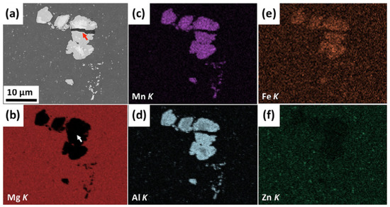
Figure 4.
(a) Combined SEM/EDS map analysis of the AZ31B-4E Mg alloy, where: (a) SEM micrograph of the investigated area of the as-received material, (b) EDS elemental map of Mg, (c) EDS elemental map of Mn, (d) EDS elemental map of Al, (e) EDS elemental map of Fe, and (f) EDS elemental map of Zn [13].
Figure 5 reveals the microstructure of the AZ31B-4E Mg alloy in the as-received and spall recovered states. In addition to the large Al-Mn clusters, the magnesium matrix is uniformly distributed with submicron-sized Al-Mn particles that are spaced closely apart. Due to the process-induced cracking of second phase Al-Mn intermetallic inclusions and their weak interface strengths, Farbaniec et al. [13] concluded that strengthening AZ31B-4E magnesium alloy via the ECAE process had a negative impact on its microstructure and, as a result, detrimental to the spall behavior. They asserted that it is likely that the clusters of inclusions seen on the fracture surface of this magnesium alloy, as illustrated in Figure 5(2b), developed during the ECAE process rather than during shock compression. In spite of this, the positions of the clusters on the fracture surface and perhaps more importantly, their frequency indicate that these inclusions serve as initiation sites for spall failure. Additionally, they proposed that nanovoid formation at the interfaces between the intermetallic inclusions and the magnesium matrix revealed in Figure 6 dominated the early phases of spall failure. However, the origin of the nanovoids nucleation, growth, and coalescence cannot be assigned to vacancy clusters and cannot be ruled out either, leaving the issue unanswered.
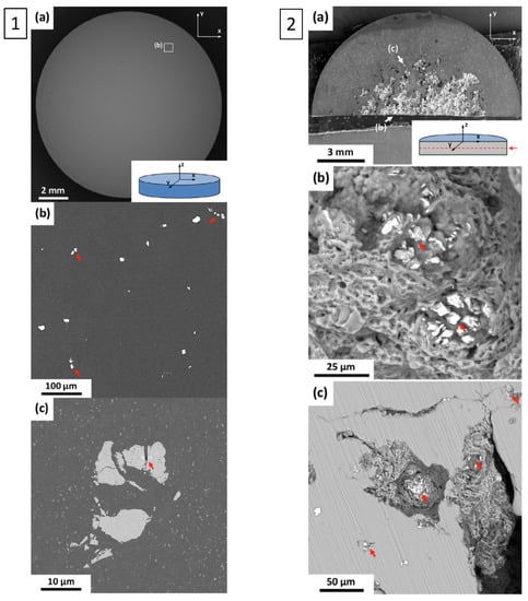
Figure 5.
SEM micrographs of the as-received AZ31B-4E Mg alloy sample in backscattered electron contrast (BSE) mode, where: 1(a) investigated sample, 1(b) zoomed-in view secondary phases of Al-Mn, and 1(c) high-magnification of the sample showing a cluster of broken secondary phases of large Al-Mn intermetallic inclusions surrounded by a smaller distribution of the same phase. SEM micrographs (BSE mode) of the mid-plane (spall plane) of the recovered AZ31B-4E Mg alloy sample shock compressed to approximately 1.7 GPa: 2(a) investigated specimen (the red arrow indicates the position of the plane of the specimen under investigation), 2(b) zoomed-in fracture surface at the center of the spall plane with intermetallic inclusions identified by arrows, and 2(c) zoomed-in fracture surface at the edge of the spall plane with intermetallic inclusions [13].
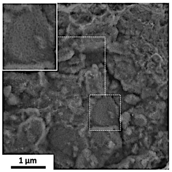
Figure 6.
SEM micrograph of the fracture surface in the center of the spall plane revealing nanovoids at the interface between the intermetallic inclusions and the magnesium matrix. The solid box is an enlarged area of the small box [13,144].
Fine grained AMX602 magnesium alloy produced using the Spinning Water Atomization Process (SWAP), which was cold-pressed and hot-extruded between 573 K and 673 K [146,147] was also investigated by Farbaniec et al. [40] to interrogate its spall response and failure characteristics. Time-resolved in situ plate impact shock experimental results for this fine grained AMX602 magnesium alloy indicate that the spall strength rose by 8% for shock stresses ranging from 1.61 GPa to 4.53 GPa, this outcome differs from that of the AZ31B-4E magnesium alloy previously described. Additionally, they found that the HEL is approximately 0.187 ± 0.011 GPa, which is close to the value determined for the AZ31B-4E magnesium alloy. Using a scanning electron microscope, they examined the morphology of the spall surface of the shock recovered samples. Their analysis show that the fracture surface of the spall recovered sample shock compressed to approximately 1.7 GPa was striated. The striations were determined to be unidirectionally aligned along the spall surface as shown in Figure 7. Farbaniec et al. [40] concluded that these striations are most likely due to the presence of the lamellae-like oxide (MgO) layers. This observation is consistent with previous observations made on spall recovered surfaces of metals consolidated by powder metallurgy.
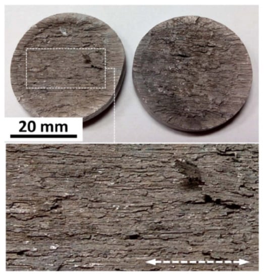
Figure 7.
Optical micrograph of the recovered sample shock compressed to approximately 1.7 GPa [40].
The striated spall surface depicted in Figure 7 is magnified and shown in Figure 8a, the striations are clearly discernible in the horizontal direction. When the pore in Figure 8a (contained by the box marked b) is enlarged even further, it is visible that the spall surface displays brittle-like fracture with just a few remnants of larger cracks (indicated by the arrows), as shown in Figure 8b. Additionally, the area designated c in Figure 8b exhibits a brittle-like phase on the fracture surface (designated as ii in Figure 8c), demarcated from the ductile region by a major crack, which is most likely an intermetallic inclusion. However, a well-developed ductile fracture zone with voids that are nanometer to micrometer in size surrounds this brittle-like phase. Within the voids, only a few precipitates thought to represent intermetallic AlCa compounds are visible (indicated by the arrows). Another intriguing finding was made by Farbaniec et al. [40] regarding an unusual feature inside the pore (see Figure 8d), and they came to the conclusion that a homogeneous and uniform microstructure is not always produced by the cold compaction process of elemental powder blends followed by hot-extrusion. These kinds of heterogeneity are often undesired and might cause the material to have non-uniform properties. They hypothesized that these microstructural changes in the material had an impact on local variations in spall strength values.
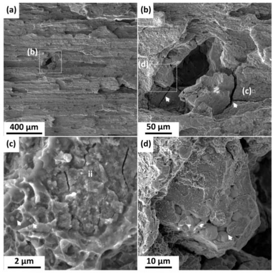
Figure 8.
SEM micrographs of the fracture surface of the recovered AMX602 magnesium shock compressed to 1.7 GPa: (a) Magnified view of the striated spall surface, (b) closeup view of the void shown in subfigure (a,c) intermetallic Al2Ca compound surrounded by nanometer and micrometer size voids, (d) internal voids or microporosity in the microstructure of the as-processed Mg alloy [40].
Figure 9b shows isolated cracks inside the spall zone extending several hundred microns that were discovered in the recovered sample shock compressed to roughly 0.9 GPa. The spall damage was characterized as having several isolated horizontal fractures connected by vertical cracks within the spall zone (shown in Figure 9b by the arrows). At higher shock stresses, such discontinuous damage zones are likely to grow and develop into a distinct spall plane. Figure 9c depicts an enlarged view of the fracture surface of an isolated area marked c inside the spall zone shown in Figure 9b. Figure 9c clearly reveals that the spall surface is occupied by nano and submicron size voids (designated as nv and mv, respectively). When both homogeneous and heterogeneous nucleation of voids are simultaneously activated by the application of high enough tensile stresses, mixed mode failure in metals and metallic alloys can occur. Generally, it is recognized that low angle grain boundaries, fine impurities and precipitates, dislocation tangles and networks, and vacancy clusters are probable homogenous nucleation sites for nanovoids [32,106]. Conversely, it is recognized that high-angle grain boundaries, inclusions, and second-phase particles might serve as heterogeneous nucleation sites for microvoids [32,106]. The spall surface was also found to be inhabited by multiple AlCa-based intermetallic compounds (labeled as ii in Figure 9c), as well as closely spaced submicron-sized precipitates, according to Farbaniec et al. [40]. The onset of spall failure in the sample was most likely caused by these microstructural flaws. Farbaniec et al. [40] proposed that the dominant failure mechanisms of spallation for this fine grained AMX602 Mg alloy are driven by the nucleation, growth, and coalescence of nanovoids and microvoids, based on these fractographic investigations.
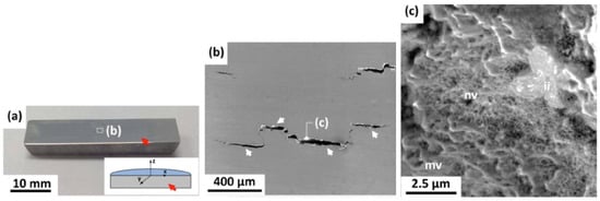
Figure 9.
(a) Optical micrographs of the cross-sections of the recovered sample shock compressed to approximately 0.9 GPa, (b) SEM investigation of the damage zone showing isolated cracks within the spall plane, and (c) a view within the crack designated c showing micron-size or largervoid-like features (mv), nanovoids (nv), and intermetallic inclusions (ii) [40].
3.4. Aluminum
Through plate impact shock recovery experiments, the substructure and microstructure of shock compressed FCC metals and metallic alloys have been thoroughly investigated [12,43,148,149,150,151,152,153,154,155,156]. For many years, researchers have employed these experiments to investigate substructure and microstructure evolution, then develop structure-property relationships under the influence of uniaxial strain. To better understand the underlying basic structure-property relationships during shock compression, Williams et al. [11,12,149] performed a comprehensive investigation on 1100 commercially pure aluminum.
Time-resolved in situ spall experiments were carried out by Williams et al. [11] and their results reveal that the spall strength of 1100-O aluminum increased between the shock stress range of 4 GPa and 8.3 GPa, then droped after that. They discovered that the substructure of the 1100-O aluminum significantly changes between 4 GPa and 9 GPa based on results derived from shock recovery experiments. This discovery, along with the outcomes of the spall recovery experiments (see Figure 10), suggests that the material shock hardened and that the predominant fracture mode for shock stresses up to around 8.3 GPa was ductile fracture by void nucleation, growth, and coalescence. Beyond 8.3 GPa, however, the material shock softened, presumably as a result of substructure reorganization (dynamic recovery), and flat surfaces created by brittle intergranular fracture by decohesion along lamellar boundaries was the predominant fracture mechanism, as shown in Figure 11. On the fracture surface, isolated pockets of nanovoids were observed, but it was unclear how the nanovoids affected the fracture and dynamic recovery processes. Microhardness studies indicate an increase in residual hardness over the whole shock stress range investigated, verifying that the material shock hardened up to about 8.3 GPa while also pointing to the absence of thermal softening across the entire shock stress range. However, under shock loading, thermal effects on dynamic recovery were present.
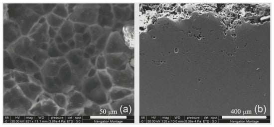
Figure 10.
SEM micrographs of the 1100-O aluminum shock compressed to 6 GPa showing (a) dimples on the fracture surface and (b) the cross-sectional view of the fractured sample showing voids below the spall plane [149].
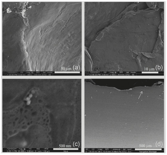
Figure 11.
SEM micrographs of the 1100-O aluminum shock compressed to 9 GPa showing (a) intergranular spall fracture surface, (b) an enlarged view of the intergranular spall fracture surface with tongues, (c) nanovoids in isolated areas of the fracture surface, and (d) the cross-sectional view of the fractured sample [149].
In an effort to further the state-of-the-art in void nucleation, growth, and coalescence with respect to aluminum alloys; Williams et al. [14] performed symmetric real-time (in situ) and end-state (ex-situ recovery) plate impact shock experiments to investigate the spall response and role of second phase intermetallic particles on the spall properties of both 5083-H321 and 5083-ECAE + 30% cold-rolled (CR) aluminum alloys. The average Hugoniot Elastic Limit (HEL) increases by 78% after mechanically processing 5083-H321 aluminum using Equal Channel Angular Extrusion (ECAE) and then cold rolling to a 30% reduction in height, according to the findings of real-time plate impact studies. However, the in situ experiments did not show this notable increase in spall strength. The in situ results for the 5083-H321 aluminum shock compressed to 1.45 GPa and 2.88 GPa shock stress, respectively, show no appreciable change in the spall strength. Nevertheless, compared to their 5083-H321 aluminum equivalent, the spall strength of the 5083-ECAE + 30% CR aluminum shock compressed to the same stress levels reduced by 37% and 23%, respectively. The second phase intermetallic Mn-Fe rich particles de-bonded from the aluminum matrix during shock compression and were potential void nucleation sites in both materials, as determined from end-state spall recovery experiments. The findings of the ex-situ spall recovery experiments further demonstrate that void nucleation, growth, and coalescence cause spallation in both materials. For the 5083-ECAE + 30% CR aluminum, the overwhelming evidence indicates that spall failure occurs along the realigned intermetallic Mn-Fe rich particles, and this may be the cause of the reduction in spall strength as a function of peak shock stress. The ensuing spall plane in the 5083-H321 aluminum is highly localized, as shown in Figure 12a, but that of the 5083-ECAE + 30% CR aluminum meanders throughout a large damage zone made up of many cracks, as seen in Figure 12b. As shown in Figure 13, mixed-mode (ductile-brittle) failure was evident. Some areas reveal dimples as a consequence of void nucleation, growth, and coalescence with other isolated areas revealing evidence of brittle fracture. This mixed-mode failure is a consequence of simultaneous homogeneous and heterogeneous void nucleation and was the dominant failure mechanism for 5083-H321 aluminum.
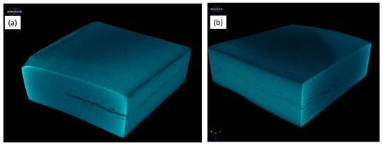
Figure 12.
X-ray microCT scans of soft recovered (a) 5083-H321aluminum and (b) 5083-ECAE + 30% CR aluminum samples shock compressed to approximately 1.46 GPa [14].
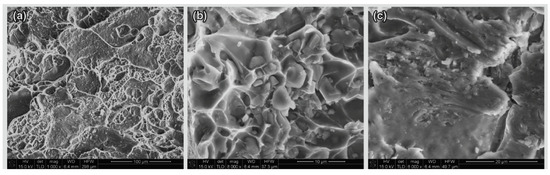
Figure 13.
SEM micrographs of the fracture surface of 5083-H321 aluminum sample shock compressed to approximately 2.96 GPa. (a) Areas consisting of dimples resulting from void nucleation, growth, and coalescence with isolated areas of brittle fracture, (b) second phase Mn-Fe rich particles within the void dimples, and (c) smooth brittle-like surface [14].
In order to study the effects of microstructure on the spall strength of four distinct types of aluminum (high purity, low porosity, 2024-T4, and 7075-T6), Wang et al. [43] simultaneously conducted time-resolved in situ spall experiments and spall recovery experiments. They found that the high density, high purity (Al HP) aluminum exhibited a higher spall strength than the low-porosity pure aluminum, but that the 2024-T4 aluminum had the highest spall strength followed by the 7075-T6 aluminum. They ascribed these findings to the smaller amount of impurities at the grain boundaries in the Al HP samples compared to those observed in the low porosity pure aluminum based on their metallographic analyses of the shock recovered samples. They came to the conclusion that there was improved resistance to void nucleation because of the decreased impurity density at the grain boundaries. At relatively low velocities, Wang et al. [43] found that, comparatively low amounts of micro-voids are nucleated in the Al HP aluminum and then grow but do not normally coalesce. On the other hand, at higher impact velocities, the micro-voids grow then coalesce to form large cracks, which then leads to spall fracture. Their micrographs unmistakably show that the micro-voids nucleate and grow largely along grain boundaries. In addition, Wang et al. [43] were able to demonstrate through spall recovery experiments carried out at approximately 300 m/s on 2024-T4 and 7075-T6 aluminum, respectively, that the majority of microvoids and/or cracks were heterogeneously nucleated at second phase particles by particle-matrix debonding at the interface.
In an attempt to investigate the effects of microstructure on the spall fracture morphology in high-purity and low-impurity aluminum samples, Brewer et al. [144] employed laser shock experiments to induced spall failure at strain rates ranging from 2 × 10 s to 5 × 10 s. Their samples were made from high-purity recrystallized aluminum as well as low-impurity aluminum alloys that were cold-rolled and recrystallized, both of which included 3% weight magnesium. Their findings unambiguously show that the shock compressed recrystallized pure aluminum exhibited spall fracture surfaces characterized by transgranular ductile dimpling. A recrystallized aluminum-magnesium alloy with a grain size of 50 m also showed fewer ductile spall surfaces, which were predominately transgranular fracture, with some isolated transgranular ductile dimpling at the higher strain rates. The recrystallized alloy samples with an average grain size of around 23 m that were spalled at higher rates did not show transgranular ductile dimpling. The spall failure surfaces in the cold-rolled alloy samples consist of brittle intergranular and transgranular fractures. Brewer et al. [144] correlated the measured spall strengths to the resulting spall morphologies and found that the measured spall strengths increase with increasing ductile fracture character and that spall failure preferentially follows grain boundaries, as shown in their micrographs. This implies that grain size can play a significant role in the spall failure characteristic and fracture surface morphology.
4. Concluding Remarks
The primary objective of this review paper was to elucidate the role of void nucleation, growth, and coalescence on spall failure in light metals such as magnesium and aluminum alloys. Based on the review of the open literature, the preponderance of evidence show that:
- (1)
- Homogeneous and heterogeneous nucleation of voids and how they grow and coalesced play a significant role in spall failure.
- (2)
- As-received microstructure and its evolution is crucial to understanding spallation.
- (3)
- Second phase particles and intermetallics strongly influence spall failure during shock compression, in that;
- -
- Changes in density across the matrix-precipitate interface can lead to significant impedance mismatch from which potential void nucleation sites can initiate via matrix-precipitate debonding or precipitate cracking during the shock compression phase.
- -
- Larger particles in conventional alloys, in that particles greater than 100 nm tend to have incoherent interfaces with the matrix that are mechanically weaker than fully coherent ones and therefore, can debond from the matrix during shock compression to become potential void nucleation site.
- -
- Reinforcing/strengthening secondary phases tend to be harder, typical examples include stoichiometric compounds such as ceramics and intermetallics phases and tend to fragment or cleave during the shock compression phase and act as potential void nucleation sites.
- (4)
- Void nucleation, growth, and coalescence is prevalent in light metals such as HCP magnesium and FCC aluminum alloys.
- (5)
- Quantifying damage and predicting spall failure through modeling has proven to be an invaluable tool in developing a fundamental understanding of void nucleation, growth, and coalescence and consequent spall failure.
- (6)
- Since new alloys are currently been developed, more experimental and modeling research are needed to further understand how spall failure initiate, grow, and coalesce in these new alloys.
Funding
This research received no external funding.
Institutional Review Board Statement
Not applicable.
Informed Consent Statement
Not applicable.
Data Availability Statement
Not applicable.
Acknowledgments
The author is grateful to Debjoy Mallick for providing the data used in Figure 2 and reviewing the manuscript.
Conflicts of Interest
The author declares no conflict of interest.
References
- Antoun, T.; Seaman, L.; Curran, D.R.; Kanel, G.I.; Razorenov, S.V.; Utkin, A.V. Spall Fracture; Springer Science & Business Media: Berlin/Heidelberg, Germany, 2003. [Google Scholar]
- Hopkinson, B.X. A method of measuring the pressure produced in the detonation of high, explosives or by the impact of bullets. Philos. Trans. R. Soc. Lond. Ser. A Contain. Pap. Math. Phys. Character 1914, 213, 437–456. [Google Scholar]
- Zurek, A.; Thissell, W.; Johnson, J.; Tonks, D.; Hixson, R. Micromechanics of spall and damage in tantalum. J. Mater. Process. Technol. 1996, 60, 261–267. [Google Scholar] [CrossRef]
- Grady, D. The spall strength of condensed matter. J. Mech. Phys. Solids 1988, 36, 353–384. [Google Scholar] [CrossRef]
- Kanel, G. Distortion of the wave profiles in an elastoplastic body upon spalling. J. Appl. Mech. Tech. Phys. 2001, 42, 358–362. [Google Scholar] [CrossRef]
- Chen, X.; Asay, J.; Dwivedi, S.; Field, D. Spall behavior of aluminum with varying microstructures. J. Appl. Phys. 2006, 99, 023528. [Google Scholar] [CrossRef]
- Trivedi, P.; Asay, J.; Gupta, Y.; Field, D. Influence of grain size on the tensile response of aluminum under plate-impact loading. J. Appl. Phys. 2007, 102, 083513. [Google Scholar] [CrossRef]
- Moshe, E.; Eliezer, S.; Dekel, E.; Ludmirsky, A.; Henis, Z.; Werdiger, M.; Goldberg, I.; Eliaz, N.; Eliezer, D. An increase of the spall strength in aluminum, copper, and Metglas at strain rates larger than 107 s−1. J. Appl. Phys. 1998, 83, 4004–4011. [Google Scholar] [CrossRef]
- Kanel, G.; Razorenov, S.; Utkin, A.; Fortov, V.; Baumung, K.; Karow, H.; Rusch, D.; Licht, V. Spall strength of molybdenum single crystals. J. Appl. Phys. 1993, 74, 7162–7165. [Google Scholar] [CrossRef]
- Kanel, G.; Razorenov, S.; Bogatch, A.; Utkin, A.; Fortov, V.; Grady, D. Spall fracture properties of aluminum and magnesium at high temperatures. J. Appl. Phys. 1996, 79, 8310–8317. [Google Scholar] [CrossRef]
- Williams, C.; Ramesh, K.; Dandekar, D. Spall response of 1100-O aluminum. J. Appl. Phys. 2012, 111, 123528. [Google Scholar] [CrossRef]
- Williams, C.; Chen, C.; Ramesh, K.; Dandekar, D. The effects of cold rolling on the microstructural and spall response of 1100 aluminum. J. Appl. Phys. 2013, 114, 093502. [Google Scholar] [CrossRef]
- Farbaniec, L.; Williams, C.; Kecskes, L.; Ramesh, K.; Becker, R. Microstructural effects on the spall properties of ECAE-processed AZ31B magnesium alloy. Int. J. Impact Eng. 2016, 98, 34–41. [Google Scholar] [CrossRef]
- Williams, C.; Sano, T.; Walter, T.; Bradley, J.; Kecskes, L. The role of second phase intermetallic particles on the spall failure of 5083 aluminum. J. Dyn. Behav. Mater. 2016, 2, 476–483. [Google Scholar] [CrossRef]
- Agarwal, G.; Dongare, A.M. Shock wave propagation and spall failure in single crystal Mg at atomic scales. J. Appl. Phys. 2016, 119, 145901. [Google Scholar] [CrossRef]
- Agarwal, G.; Dongare, A.M. Defect and damage evolution during spallation of single crystal Al: Comparison between molecular dynamics and quasi-coarse-grained dynamics simulations. Comput. Mater. Sci. 2018, 145, 68–79. [Google Scholar] [CrossRef]
- Smith, J. Three Low-Pressure Spall Thresholds in Copper; ASTM International: West Conshohocken, PA, USA, 1963. [Google Scholar]
- Skidmore, I. An introduction to shock waves in solids. Appl. Mater. Res. 1965, 4, 131–147. [Google Scholar]
- Breed, B.; Mader, C.L.; Venable, D. Technique for the Determination of Dynamic-Tensile-Strength Characteristics. J. Appl. Phys. 1967, 38, 3271–3275. [Google Scholar] [CrossRef]
- Tuler, F.R.; Butcher, B.M. A criterion for the time dependence of dynamic fracture. Int. J. Fract. Mech. 1968, 4, 431–437. [Google Scholar] [CrossRef]
- Tobolsky, A.; Eyring, H. Mechanical properties of polymeric materials. J. Chem. Phys. 1943, 11, 125–134. [Google Scholar] [CrossRef]
- Zhurkov, S.N. Kinetic concept of the strength of solids. Int. J. Fract. Mech. 1965, 1, 311–323. [Google Scholar] [CrossRef]
- Curran, D.; Seaman, L.; Shockey, D. Dynamic failure of solids. Phys. Rep. 1987, 147, 253–388. [Google Scholar] [CrossRef]
- Rigg, P.; Gupta, Y. Real-time X-ray diffraction to examine elastic–plastic deformation in shocked lithium fluoride crystals. Appl. Phys. Lett. 1998, 73, 1655–1657. [Google Scholar] [CrossRef]
- Gupta, Y.; Zimmerman, K.; Rigg, P.; Zaretsky, E.; Savage, D.; Bellamy, P. Experimental developments to obtain real-time x-ray diffraction measurements in plate impact experiments. Rev. Sci. Instrum. 1999, 70, 4008–4014. [Google Scholar] [CrossRef]
- Turneaure, S.J.; Gupta, Y. Real time synchrotron X-ray diffraction measurements to determine material strength of shocked single crystals following compression and release. J. Appl. Phys. 2009, 106, 033513. [Google Scholar] [CrossRef]
- Barker, L.; Hollenbach, R. Interferometer technique for measuring the dynamic mechanical properties of materials. Rev. Sci. Instrum. 1965, 36, 1617–1620. [Google Scholar] [CrossRef]
- Barker, L.; Hollenbach, R. Laser interferometer for measuring high velocities of any reflecting surface. J. Appl. Phys. 1972, 43, 4669–4675. [Google Scholar] [CrossRef]
- Strand, O.T.; Goosman, D.; Martinez, C.; Whitworth, T.; Kuhlow, W. Compact system for high-speed velocimetry using heterodyne techniques. Rev. Sci. Instrum. 2006, 77, 083108. [Google Scholar] [CrossRef]
- Barbee, T.; Seaman, L.; Crewdson, R. Dynamic Fracture Criteria of Homogeneous Materials; Technical Report; Stanford Research Institute: Menlo Park CA, USA, 1970. [Google Scholar]
- Seaman, L.; Barbee, T., Jr.; Curran, D. Dynamic Fracture Criteria of Homogeneous Materials; Technical Report; Stanford Research Institute: Menlo Park, CA, USA, 1972. [Google Scholar]
- Meyers, M.A.; Aimone, C.T. Dynamic fracture (spalling) of metals. Prog. Mater. Sci. 1983, 28, 1–96. [Google Scholar] [CrossRef]
- Meyers, M.A.; Staudhammer, K.P.; Murr, L.E. Metallurgical Applications of Shock-Wave and High-Strain-Rate Phenomena; Marcel Dekker: New York, NY, USA, 1986. [Google Scholar]
- Gray, G.T., III. Shock Recovery Experiments: An Assessment; Technical Report; Los Alamos National Lab. (LANL): Los Alamos, NM, USA, 1989.
- Meyers, M.A. Dynamic Behavior of Materials; John Wiley & Sons: Hoboken, NJ, USA, 1994. [Google Scholar]
- Isbell, W.M. Shock Waves: Measuring the Dynamic Response of Materials; Imperial College Press: London, UK, 2005. [Google Scholar]
- Flanagan, R.; Fensin, S.; Meyers, M. The role of pre-existing heterogeneities in materials under shock and spall. Appl. Phys. Rev. 2022, 9, 011305. [Google Scholar] [CrossRef]
- Williams, C.L. Structure-property relationships under extreme dynamic environments: Shock recovery experiments. Synth. SEM Lect. Exp. Mech. 2019, 2, 1–155. [Google Scholar]
- Kanel, G.I.; Razorenov, S.V.; Fortov, V.E.; Fortov, V. Shock-Wave Phenomena and the Properties of Condensed Matter; Springer Science & Business Media: Berlin/Heidelberg, Germany, 2004. [Google Scholar]
- Farbaniec, L.; Williams, C.; Kecskes, L.; Becker, R.; Ramesh, K. Spall response and failure mechanisms associated with a hot-extruded AMX602 Mg alloy. Mater. Sci. Eng. A 2017, 707, 725–731. [Google Scholar] [CrossRef]
- De Rességuier, T.; Hemery, S.; Lescoute, E.; Villechaise, P.; Kanel, G.; Razorenov, S. Spall fracture and twinning in laser shock-loaded single-crystal magnesium. J. Appl. Phys. 2017, 121, 165104. [Google Scholar] [CrossRef]
- Dai, Z.; Lu, L.; Chai, H.; Xiao, X.; Gong, X.; Luo, S. Mechanical properties and fracture behavior of Mg–3Al–1Zn alloy under high strain rate loading. Mater. Sci. Eng. A 2020, 789, 139690. [Google Scholar] [CrossRef]
- Wang, Y.; Qi, M.; He, H.; Wang, L. Spall failure of aluminum materials with different microstructures. Mech. Mater. 2014, 69, 270–279. [Google Scholar] [CrossRef]
- Whelchel, R.; Kennedy, G.; Dwivedi, S.; Sanders, T., Jr.; Thadhani, N. Spall behavior of rolled aluminum 5083-H116 plate. J. Appl. Phys. 2013, 113, 233506. [Google Scholar] [CrossRef]
- Clow, B. Magnesium: The lightest one. In Metallic Materials for Lightweight Applications, Proceedings of the 40th Sagamore Army Materials Research Conference, Plymouth, MA, USA, 30 August–2 September 1993; Government Printing Office: Washington, DC, USA, 1993; pp. 235–239. [Google Scholar]
- Jones, T.; Kondoh, K. Initial Evaluation of Advanced Powder Metallurgy Magnesium Alloys for Dynamic Applications; Technical Report; Army Research Lab: Aberdeen Proving Ground, MD, USA, 2009. [Google Scholar]
- Mallick, D.D.; Prameela, S.E.; Ozturk, D.; Williams, C.L.; Kang, M.; Valentino, G.M.; Lloyd, J.T.; Wilkerson, J.W.; Weihs, T.P.; Ramesh, K. Spall strength in alloyed magnesium: A compendium of research efforts from the CMEDE 10-year effort. Mech. Mater. 2021, 162, 104065. [Google Scholar] [CrossRef]
- Hufnagel, T.C.; Lloyd, J.T.; Weihs, T.P.; Kecskes, L.J.; Sano, T. Magnesium alloy design: Examples from the Materials in Extreme Dynamic Environments Metals Collaborative Research Group. Mech. Mater. 2022, 165, 104136. [Google Scholar] [CrossRef]
- Wei, Q.; Ramesh, K.; Hufnagel, T.C.; Wilkerson, J.; El-Awady, J.A.; Kimberley, J.; Ravaji, B.; Joshi, S.P. Insights from the MEDE program: An overview of microstructure–property linkages in the dynamic behaviors of magnesium alloys. Mech. Mater. 2021, 163, 104084. [Google Scholar] [CrossRef]
- Kelley, E.; Hosford, W. Plane-strain compression of magnesium and magnesium alloy crystals. Trans. Met. Soc. AIME 1968, 242, 5–13. [Google Scholar]
- Yoo, M. Slip, twinning, and fracture in hexagonal close-packed metals. Metall. Trans. A 1981, 12, 409–418. [Google Scholar] [CrossRef]
- Li, B.; Ma, E. Pyramidal slip in magnesium: Dislocations and stacking fault on the {10 1 1} plane. Philos. Mag. 2009, 89, 1223–1235. [Google Scholar] [CrossRef]
- Dixit, N.; Xie, K.Y.; Hemker, K.J.; Ramesh, K. Microstructural evolution of pure magnesium under high strain rate loading. Acta Mater. 2015, 87, 56–67. [Google Scholar] [CrossRef]
- Kannan, V.; Hazeli, K.; Ramesh, K. The mechanics of dynamic twinning in single crystal magnesium. J. Mech. Phys. Solids 2018, 120, 154–178. [Google Scholar] [CrossRef]
- Agnew, S.R.; Duygulu, Ö. Plastic anisotropy and the role of non-basal slip in magnesium alloy AZ31B. Int. J. Plast. 2005, 21, 1161–1193. [Google Scholar] [CrossRef]
- Hong, S.G.; Park, S.H.; Lee, C.S. Role of {10–12} twinning characteristics in the deformation behavior of a polycrystalline magnesium alloy. Acta Mater. 2010, 58, 5873–5885. [Google Scholar] [CrossRef]
- Yoshinaga, H.; Horiuchi, R. Deformation mechanisms in magnesium single crystals compressed in the direction parallel to hexagonal axis. Trans. Jpn. Inst. Met. 1963, 4, 1–8. [Google Scholar] [CrossRef]
- Stohr, J.F.; Poirier, J.P. Etude en microscopie electronique du glissement pyramidal {1122}< 1123> dans le magnesium. Philos. Mag. 1972, 25, 1313–1329. [Google Scholar]
- Yoo, M.; Morris, J.; Ho, K.; Agnew, S. Nonbasal deformation modes of HCP metals and alloys: Role of dislocation source and mobility. Metall. Mater. Trans. A 2002, 33, 813–822. [Google Scholar] [CrossRef]
- Yoo, M.; Agnew, S.; Morris, J.; Ho, K. Non-basal slip systems in HCP metals and alloys: Source mechanisms. Mater. Sci. Eng. A 2001, 319, 87–92. [Google Scholar] [CrossRef]
- Koike, J.; Kobayashi, T.; Mukai, T.; Watanabe, H.; Suzuki, M.; Maruyama, K.; Higashi, K. The activity of non-basal slip systems and dynamic recovery at room temperature in fine-grained AZ31B magnesium alloys. Acta Mater. 2003, 51, 2055–2065. [Google Scholar] [CrossRef]
- Meredith, C.S.; Lloyd, J.T.; Sano, T. The quasi-static and dynamic response of fine-grained Mg alloy AMX602: An experimental and computational study. Mater. Sci. Eng. A 2016, 673, 73–82. [Google Scholar] [CrossRef]
- Roberts, C.S. Magnesium and Its Alloys; Wiley: Hoboken, NJ, USA, 1960. [Google Scholar]
- Reed-Hill, R.E.; Robertson, W.D. Deformation of magnesium single crystals by nonbasal slip. JOM 1957, 9, 496–502. [Google Scholar] [CrossRef]
- Agnew, S.; Yoo, M.; Tome, C. Application of texture simulation to understanding mechanical behavior of Mg and solid solution alloys containing Li or Y. Acta Mater. 2001, 49, 4277–4289. [Google Scholar] [CrossRef]
- Kleiner, S.; Uggowitzer, P.J. Mechanical anisotropy of extruded Mg–6% Al–1% Zn alloy. Mater. Sci. Eng. A 2004, 379, 258–263. [Google Scholar] [CrossRef]
- Nave, M.D.; Barnett, M.R. Microstructures and textures of pure magnesium deformed in plane-strain compression. Scr. Mater. 2004, 51, 881–885. [Google Scholar] [CrossRef]
- Serra, A.; Bacon, D. A new model for {10 1 2} twin growth in hcp metals. Philos. Mag. A 1996, 73, 333–343. [Google Scholar] [CrossRef]
- Kucherov, L.; Tadmor, E. Twin nucleation mechanisms at a crack tip in an hcp material: Molecular simulation. Acta Mater. 2007, 55, 2065–2074. [Google Scholar] [CrossRef]
- Serra, A.; Bacon, D.; Pond, R. The crystallography and core structure of twinning dislocations in HCP metals. Acta Metall. 1988, 36, 3183–3203. [Google Scholar] [CrossRef]
- Serra, A.; Pond, R.; Bacon, D. Computer simulation of the structure and mobility of twinning disclocations in hcp metals. Acta Metall. Mater. 1991, 39, 1469–1480. [Google Scholar] [CrossRef]
- Li, B.; Joshi, S.P.; Almagri, O.; Ma, Q.; Ramesh, K.; Mukai, T. Rate-dependent hardening due to twinning in an ultrafine-grained magnesium alloy. Acta Mater. 2012, 60, 1818–1826. [Google Scholar] [CrossRef]
- Renganathan, P.; Winey, J.; Gupta, Y. Shock compression and release of a-axis magnesium single crystals: Anisotropy and time dependent inelastic response. J. Appl. Phys. 2017, 121, 035901. [Google Scholar] [CrossRef]
- Yoshinaga, H.; Obara, T.; Morozumi, S. Twinning deformation in magnesium compressed along the C-axis. Mater. Sci. Eng. 1973, 12, 255–264. [Google Scholar] [CrossRef]
- Kanel, G.; Garkushin, G.; Savinykh, A.; Razorenov, S.; De Resseguier, T.; Proud, W.; Tyutin, M. Shock response of magnesium single crystals at normal and elevated temperatures. J. Appl. Phys. 2014, 116, 143504. [Google Scholar] [CrossRef]
- Yang, Q.; Ghosh, A. Deformation behavior of ultrafine-grain (UFG) AZ31B Mg alloy at room temperature. Acta Mater. 2006, 54, 5159–5170. [Google Scholar] [CrossRef]
- Williams, C.L.; Kale, C.; Turnage, S.A.; Shannahan, L.S.; Li, B.; Solanki, K.N.; Becker, R.; Hufnagel, T.C.; Ramesh, K.T. Real-time observation of twinning-detwinning in shock-compressed magnesium via time-resolved in situ synchrotron XRD experiments. Phys. Rev. Mater. 2020, 4, 083603. [Google Scholar] [CrossRef]
- Li, B.; Joshi, S.; Azevedo, K.; Ma, E.; Ramesh, K.; Figueiredo, R.; Langdon, T. Dynamic testing at high strain rates of an ultrafine-grained magnesium alloy processed by ECAP. Mater. Sci. Eng. A 2009, 517, 24–29. [Google Scholar] [CrossRef]
- Bay, B.; Hansen, N.; Kuhlmann-Wilsdorf, D. Deformation structures in lightly rolled pure aluminium. Mater. Sci. Eng. A 1989, 113, 385–397. [Google Scholar] [CrossRef]
- Hughes, D.; Hansen, N. Microstructural evolution in nickel during rolling and torsion. Mater. Sci. Technol. 1991, 7, 544–553. [Google Scholar] [CrossRef]
- Bay, B.; Hansen, N.; Hughes, D.; Kuhlmann-Wilsdorf, D. Overview no. 96 evolution of fcc deformation structures in polyslip. Acta Metall. Mater. 1992, 40, 205–219. [Google Scholar] [CrossRef]
- Bay, B.; Hansen, N.; Kuhlmann-Wilsdorf, D. Microstructural evolution in rolled aluminium. Mater. Sci. Eng. A 1992, 158, 139–146. [Google Scholar] [CrossRef]
- Driver, J.; Jensen, D.J.; Hansen, N. Large strain deformation structures in aluminium crystals with rolling texture orientations. Acta Metall. Mater. 1994, 42, 3105–3114. [Google Scholar] [CrossRef]
- Rosen, G.I.; Jensen, D.J.; Hughes, D.A.; Hansen, N. Microstructure and local crystallography of cold rolled aluminium. Acta Metall. Mater. 1995, 43, 2563–2579. [Google Scholar] [CrossRef]
- Hansen, N.; Jensen, D.J. Development of microstructure in FCC metals during cold work. Philos. Trans. R. Soc. London. Ser. A Math. Phys. Eng. Sci. 1999, 357, 1447–1469. [Google Scholar] [CrossRef]
- Hughes, D. Microstructure evolution, slip patterns and flow stress. Mater. Sci. Eng. A 2001, 319, 46–54. [Google Scholar] [CrossRef]
- Weertmann, J.; Weertmann, J.; Paufler, P. Elementary Dislocation Theory. Cryst. Res. Technol. 1994, 29, 814. [Google Scholar]
- Hull, D.; Bacon, D.J. Introduction to Dislocations; Butterworth-Heinemann: Oxford, UK, 2001. [Google Scholar]
- Hirth, J.; Lothe, J. Theory of Dislocations, 2nd ed.; Krieger Publishing Company: Malabar, FL, USA, 1992. [Google Scholar]
- Hughes, D. The Development of High Angle Deformation Boundaries and Local Orientations in Aluminum; Technical Report; Sandia National Lab. (SNL-CA): Livermore, CA, USA, 1996.
- Kuhlmann-Wilsdorf, D. Theory of plastic deformation:-properties of low energy dislocation structures. Mater. Sci. Eng. A 1989, 113, 1–41. [Google Scholar] [CrossRef]
- Gray, G. Influence of shock-wave deformation on the structure/property behavior of materials. In High-Pressure Shock Compression of Solids; Springer: Berlin/Heidelberg, Germany, 1993; pp. 187–215. [Google Scholar]
- Gray, G., III; Huang, J. Influence of repeated shock loading on the substructure evolution of 99.99 wt.% aluminum. Mater. Sci. Eng. A 1991, 145, 21–35. [Google Scholar] [CrossRef]
- Gray, G.T. Shock-induced defects in bulk materials. MRS Online Proc. Libr. (OPL) 1997, 499, 87–98. [Google Scholar] [CrossRef]
- Kressel, H.; Brown, N. Lattice defects in shock-deformed and cold-worked nickel. J. Appl. Phys. 1967, 38, 1618–1625. [Google Scholar] [CrossRef]
- Stevens, A.; Tuler, F. Effect of Shock Precompression on the Dynamic Fracture Strength of 1020 Steel and 6061-T6 Aluminum. J. Appl. Phys. 1971, 42, 5665–5670. [Google Scholar] [CrossRef]
- Johnson, J.; Gray, G., III; Bourne, N. Effect of pulse duration and strain rate on incipient spall fracture in copper. J. Appl. Phys. 1999, 86, 4892–4901. [Google Scholar] [CrossRef]
- Murr, L. Residual microstructure-mechanical property relationships in shock-loaded metals and alloys. In Shock Waves and High-Strain-Rate Phenomena in Metals; Springer: Berlin/Heidelberg, Germany, 1981; pp. 607–673. [Google Scholar]
- Gray, G., III; Follansbee, P. Influence of Peak Pressure and Pulse Duration on Substructure Development and Threshold Stress Measurements in Shock-Loaded Copper; Technical Report; Los Alamos National Lab. (LANL): Los Alamos, NM, USA, 1987.
- Gray, G., III; Morris, C. Influence of Peak Pressure on the Substructure Evolution and Shock Wave Profiles of Ti-6Al-4V; Technical Report; Los Alamos National Lab. (LANL): Los Alamos, NM, USA, 1988.
- Escobedo, J.; Dennis-Koller, D.; Cerreta, E.; Patterson, B.; Bronkhorst, C.; Hansen, B.; Tonks, D.; Lebensohn, R. Effects of grain size and boundary structure on the dynamic tensile response of copper. J. Appl. Phys. 2011, 110, 033513. [Google Scholar] [CrossRef]
- Butcher, B.; Barker, L.; Munson, D.; Lundergan, C. Influence of stress history on time-dependent spall in metals. AIAA J. 1964, 2, 977–990. [Google Scholar] [CrossRef]
- Li, C.; Li, B.; Huang, J.; Ma, H.; Zhu, M.; Zhu, J.; Luo, S. Spall damage of a mild carbon steel: Effects of peak stress, strain rate and pulse duration. Mater. Sci. Eng. A 2016, 660, 139–147. [Google Scholar] [CrossRef]
- Kanel, G.; Razorenov, S.; Baumung, K.; Singer, J. Dynamic yield and tensile strength of aluminum single crystals at temperatures up to the melting point. J. Appl. Phys. 2001, 90, 136–143. [Google Scholar] [CrossRef]
- Boteler, J.M.; Dandekar, D.P. Dynamic Response of 5083-H131 Aluminum Alloy. AIP Conf. Proc. 2007, 955, 481. [Google Scholar]
- Shockey, D.; Seaman, L.; Curran, D. Metallurgical Effects at High Strain Rates; Rhode, R.W., Butcher, B.M., Holland, J.R., Karnes, C.H., Eds.; Plenum Press: New York, NY, USA, 1973; p. 473. [Google Scholar]
- Yu, X.; Li, T.; Li, L.; Liu, S.; Li, Y. Influence of initial texture on the shock property and spall behavior of magnesium alloy AZ31B. Mater. Sci. Eng. A 2017, 700, 259–268. [Google Scholar] [CrossRef]
- Hazell, P.; Appleby-Thomas, G.; Wielewski, E.; Stennett, C.; Siviour, C. The influence of microstructure on the shock and spall behaviour of the magnesium alloy, Elektron 675. Acta Mater. 2012, 60, 6042–6050. [Google Scholar] [CrossRef]
- Garkushin, G.; Kanel, G.; Razorenov, S. The resistance to deformation and facture of magnesium ma2-1 under shock-wave loading at 293 K and 823 K of the temperature. AIP Conf. Proc. 2012, 1, 935–938. [Google Scholar]
- Kanel, G.; Razorenov, S.; Bogatch, A.; Utkin, A.; Grady, D. Simulation of spall fracture of aluminum and magnesium over a wide range of load duration and temperature. Int. J. Impact Eng. 1997, 20, 467–478. [Google Scholar] [CrossRef]
- Pedrazas, N.A.; Worthington, D.L.; Dalton, D.A.; Sherek, P.A.; Steuck, S.P.; Quevedo, H.J.; Bernstein, A.C.; Taleff, E.M.; Ditmire, T. Effects of microstructure and composition on spall fracture in aluminum. Mater. Sci. Eng. A 2012, 536, 117–123. [Google Scholar] [CrossRef]
- Dalton, D.; Brewer, J.; Bernstein, A.; Grigsby, W.; Milathianaki, D.; Jackson, E.; Adams, R.; Rambo, P.; Schwarz, J.; Edens, A. Laser-induced spallation of aluminum and Al alloys at strain rates above 2× 10⁶ s−1. J. Appl. Phys. 2008, 104, 013526. [Google Scholar] [CrossRef]
- Fortov, V.; Kostin, V.; Eliezer, S. Spallation of metals under laser irradiation. J. Appl. Phys. 1991, 70, 4524–4531. [Google Scholar] [CrossRef]
- Williams, C.; Mallick, D.; Wilkerson, J. A concise note on deformation twinning and spall failure in magnesium at the extremes. J. Dyn. Behav. Mater. 2020, 6, 432–444. [Google Scholar] [CrossRef]
- Remington, T.; Hahn, E.; Zhao, S.; Flanagan, R.; Mertens, J.; Sabbaghianrad, S.; Langdon, T.G.; Wehrenberg, C.; Maddox, B.; Swift, D.; et al. Spall strength dependence on grain size and strain rate in tantalum. Acta Mater. 2018, 158, 313–329. [Google Scholar] [CrossRef]
- Wang, W.; Zhang, H.; Yang, M.; Jiang, P.; Yuan, F.; Wu, X. Shock and spall behaviors of a high specific strength steel: Effects of impact stress and microstructure. J. Appl. Phys. 2017, 121, 135901. [Google Scholar] [CrossRef]
- Mallick, D.; Williams, C.; Wilkerson, J. A brief review of spall failure in pure and alloyed magnesium. J. Dyn. Behav. Mater. 2020, 6, 423–431. [Google Scholar] [CrossRef]
- Yang, Y.; Yang, S.; Wang, H. Effects of microstructure on the evolution of dynamic damage of Fe50Mn30Co10Cr10 high entropy alloy. Mater. Sci. Eng. A 2021, 802, 140440. [Google Scholar] [CrossRef]
- Hornbuckle, B.; Turnage, A.; Williams, C.; Giri, A.; Casem, D.; Solanki, K.; Darling, K. Critical assessment of the extreme mechanical behavior of a stable nanocrystalline alloy under shock loading. Acta Mater. 2022, 236, 118105. [Google Scholar] [CrossRef]
- DeHoff, R.T.; Rhines, F.N. Quantitative Microscopy; McGraw-Hill: New York, NY, USA, 1968. [Google Scholar]
- Davison, L.; Stevens, A. Continuum measures of spall damage. J. Appl. Phys. 1972, 43, 988–994. [Google Scholar] [CrossRef]
- Davison, L.; Stevens, A. Thermomechanical constitution of spalling elastic bodies. J. Appl. Phys. 1973, 44, 668–674. [Google Scholar] [CrossRef]
- Davison, L.; Stevens, A.; Kipp, M. Theory of spall damage accumulation in ductile metals. J. Mech. Phys. Solids 1977, 25, 11–28. [Google Scholar] [CrossRef]
- Cochran, S.; Banner, D. Spall studies in uranium. J. Appl. Phys. 1977, 48, 2729–2737. [Google Scholar] [CrossRef]
- Gilman, J.J.; Tuler, F.R. Dynamic fracture by spallation in metals. Int. J. Fract. Mech. 1970, 6, 169–182. [Google Scholar] [CrossRef]
- Barbee, T.; Seaman, L.; Crewdson, R.; Curran, D. Dynamic fracture criteria for ductile and brittle metals. J. Mater. 1972, 7, 393–401. [Google Scholar]
- Seaman, L.; Curran, D.; Crewdson, R. Transformation of observed crack traces on a section to true crack density for fracture calculations. J. Appl. Phys. 1978, 49, 5221–5229. [Google Scholar] [CrossRef]
- Curran, D.; Shockey, D.; Seaman, L. Dynamic fracture criteria for a polycarbonate. J. Appl. Phys. 1973, 44, 4025–4038. [Google Scholar] [CrossRef]
- Shockey, D.; Seaman, L.; Curran, D. The influence of microstructural features on dynamic fracture. In Metallurgical Effects at High Strain Rates; Springer: Berlin/Heidelberg, Germany, 1973; pp. 473–499. [Google Scholar]
- Seaman, L.; Curran, D.R.; Shockey, D.A. Computational models for ductile and brittle fracture. J. Appl. Phys. 1976, 47, 4814–4826. [Google Scholar] [CrossRef]
- Shockey, D.; Curran, D.; De Carli, P. Damage in steel plates from hypervelocity impact. I. Physical changes and effects of projectile material. J. Appl. Phys. 1975, 46, 3766–3775. [Google Scholar] [CrossRef]
- Curran, D.; Seaman, L.; Shockey, D. Linking dynamic fracture to microstructural processes. In Shock Waves and High-Strain-Rate Phenomena in Metals; Springer: Boston, MA, USA, 1981; pp. 129–167. [Google Scholar]
- Shockey, D.; Curran, D.; Seaman, L. Computer modeling of microscopic failure processes under dynamic loads. In High Velocity Deformation of Solids; Springer: Berlin/Heidelberg, Germany, 1979; pp. 149–162. [Google Scholar]
- Shockey, D.; Seaman, L.; Curran, D. The micro-statistical fracture mechanics approach to dynamic fracture problems. In Dynamic Fracture; Springer: Berlin/Heidelberg, Germany, 1985; pp. 19–31. [Google Scholar]
- Kipp, M.; Grady, D. Dynamic fracture growth and interaction in one dimension. J. Mech. Phys. Solids 1985, 33, 399–415. [Google Scholar] [CrossRef]
- Grady, D. Application of survival statistics to the impulsive fragmentation of ductile rings. In Shock Waves and High-Strain-Rate Phenomena in Metals; Springer: Berlin/Heidelberg, Germany, 1981; pp. 181–192. [Google Scholar]
- Rajendran, A.; Dietenberger, M.; Grove, D. A void growth-based failure model to describe spallation. J. Appl. Phys. 1989, 65, 1521–1527. [Google Scholar] [CrossRef]
- Wang, Y.; He, H.; Wang, L. Critical damage evolution model for spall failure of ductile metals. Mech. Mater. 2013, 56, 131–141. [Google Scholar] [CrossRef]
- Becker, R. Direct numerical simulation of ductile spall failure. Int. J. Fract. 2017, 208, 5–26. [Google Scholar] [CrossRef]
- Wilkerson, J.; Ramesh, K. A dynamic void growth model governed by dislocation kinetics. J. Mech. Phys. Solids 2014, 70, 262–280. [Google Scholar] [CrossRef]
- Chen, J.; Luscher, D.J.; Fensin, S.J. The Modified Void Nucleation and Growth Model (MNAG) for Damage Evolution in BCC Ta. Appl. Sci. 2021, 11, 3378. [Google Scholar] [CrossRef]
- Mallick, D.; Parker, J.; Wilkerson, J.; Ramesh, K. Estimating void nucleation statistics in laser-driven spall. J. Dyn. Behav. Mater. 2020, 6, 268–277. [Google Scholar] [CrossRef]
- Hazell, P.; Appleby-Thomas, G.; Wielewski, E.; Escobedo, J. The shock and spall response of three industrially important hexagonal close-packed metals: Magnesium, titanium and zirconium. Philos. Trans. R. Soc. A Math. Phys. Eng. Sci. 2014, 372, 20130204. [Google Scholar] [CrossRef]
- Brewer, J.L.; Dalton, D.A.; Jackson, E.D.; Bernstein, A.C.; Grigsby, W.; Taleff, E.M.; Ditmire, T. Influence of microstructure on the spall failure of aluminum materials. Metall. Mater. Trans. A 2007, 38, 2666–2673. [Google Scholar] [CrossRef]
- Krywopusk, N.M.; Williams, C.L.; Kecskes, L.J.; Weihs, T.P. Characterization of spalled AZ31B processed by ECAE. Mater. Sci. Eng. A 2019, 767, 138298. [Google Scholar] [CrossRef]
- Kondoh, K.; Hamada, E.S.A.; Imai, H.; Umeda, J.; Jones, T. Microstructures and mechanical responses of powder metallurgy non-combustive magnesium extruded alloy by rapid solidification process in mass production. Mater. Des. 2010, 31, 1540–1546. [Google Scholar] [CrossRef]
- Kondoh, K.; Kawabata, K.; Oginuma, H. Mechanical properties and texture of hot extruded magnesium alloys via RCP process in using coarse raw powder. Magnes. Technol. 2007, 433–436. [Google Scholar]
- Mahajan, S. Metallurgical effects of planar shock waves in metals and alloys. Phys. Status Solidi (a) 1970, 2, 187–201. [Google Scholar] [CrossRef]
- Williams, C.; Chen, C.; Ramesh, K.; Dandekar, D. On the shock stress, substructure evolution, and spall response of commercially pure 1100-O aluminum. Mater. Sci. Eng. A 2014, 618, 596–604. [Google Scholar] [CrossRef]
- Minich, R.W.; Cazamias, J.U.; Kumar, M.; Schwartz, A.J. Effect of microstructural length scales on spall behavior of copper. Metall. Mater. Trans. A 2004, 35, 2663–2673. [Google Scholar] [CrossRef]
- Grady, D.E.; Asay, J.R.; Rohde, R.W.; Wise, J.L. Microstructure and mechanical properties of precipitation hardened aluminum under high rate deformation. In Material Behavior Under High Stress and Ultrahigh Loading Rates; Springer: Berlin/Heidelberg, Germany, 1983; pp. 81–100. [Google Scholar]
- Podurets, A.; Raevskii, V.; Khanzhin, V.; Lebedev, A.; Aprelkov, O.; Igonin, V.; Kondrokhina, I.; Balandina, A.; Tkachenko, M.; Petit, J.; et al. Twin structures in copper after shock and Shockless high-rate loading. Combust. Explos. Shock Waves 2011, 47, 606–614. [Google Scholar] [CrossRef]
- Peralta, P.; DiGiacomo, S.; Hashemian, S.; Luo, S.N.; Paisley, D.; Dickerson, R.; Loomis, E.; Byler, D.; McClellan, K.; D’Armas, H. Characterization of incipient spall damage in shocked copper multicrystals. Int. J. Damage Mech. 2009, 18, 393–413. [Google Scholar] [CrossRef]
- Wayne, L.; Krishnan, K.; DiGiacomo, S.; Kovvali, N.; Peralta, P.; Luo, S.; Greenfield, S.; Byler, D.; Paisley, D.; McClellan, K.; et al. Statistics of weak grain boundaries for spall damage in polycrystalline copper. Scr. Mater. 2010, 63, 1065–1068. [Google Scholar] [CrossRef]
- Millett, J.C.; Bourne, N.; Gray, G. The behavior of Ni, Ni-60Co, and Ni3Al during one-dimensional shock loading. Metall. Mater. Trans. A 2008, 39, 322–334. [Google Scholar] [CrossRef]
- Meshcheryakov, Y.I.; Divakov, A.; Zhigacheva, N.; Makarevich, I.; Barakhtin, B. Dynamic structures in shock-loaded copper. Phys. Rev. B 2008, 78, 064301. [Google Scholar] [CrossRef]
Publisher’s Note: MDPI stays neutral with regard to jurisdictional claims in published maps and institutional affiliations. |
© 2022 by the author. Licensee MDPI, Basel, Switzerland. This article is an open access article distributed under the terms and conditions of the Creative Commons Attribution (CC BY) license (https://creativecommons.org/licenses/by/4.0/).