
Comparative Study of the Metallurgical Quality of Primary and Secondary AlSi10MnMg Aluminium Alloys


 and
and 
Abstract
:1. Introduction
2. Materials and Methods
3. Results and Discussion
4. Conclusions
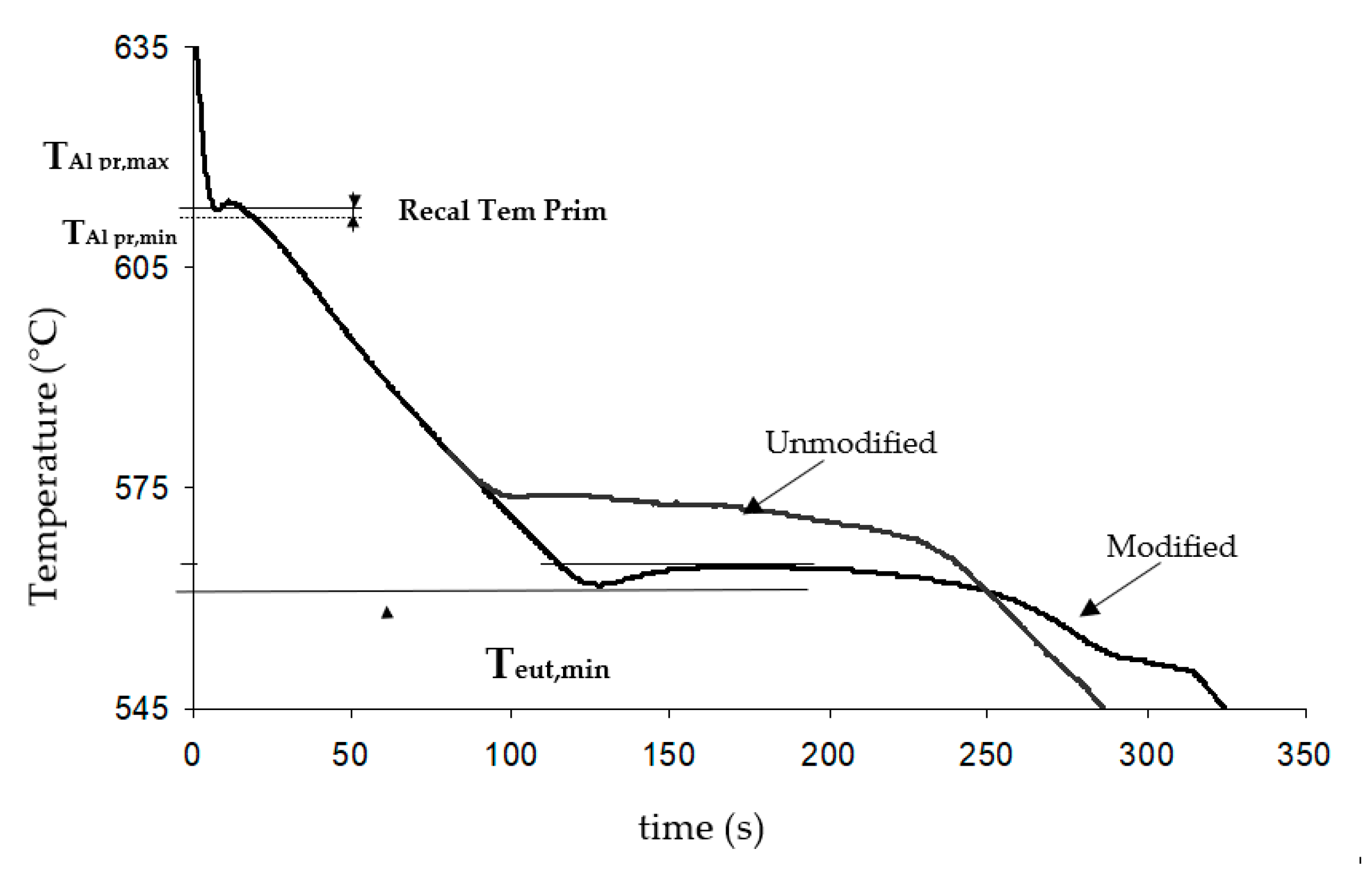
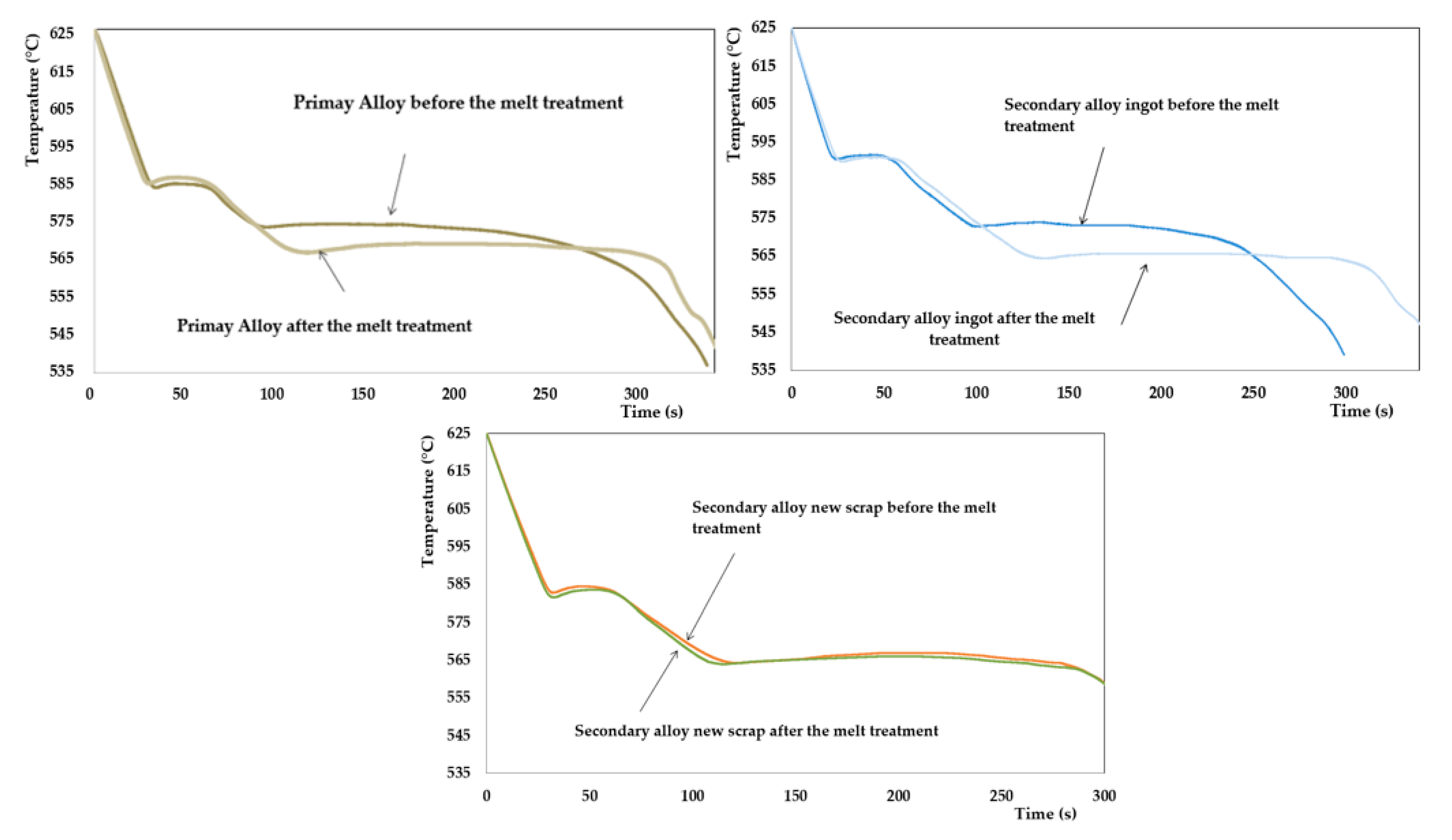
- After adding the AlSr10 master alloy, the eutectic temperatures of the three alloys were reduced significantly, achieving similar values, dropping from 573.2–573.0 °C to 566.5–563.9 °C. Additionally, high modification rates (4 on a scale of 1 to 6) were predicted for the three cases, achieving optimal metallurgical quality;
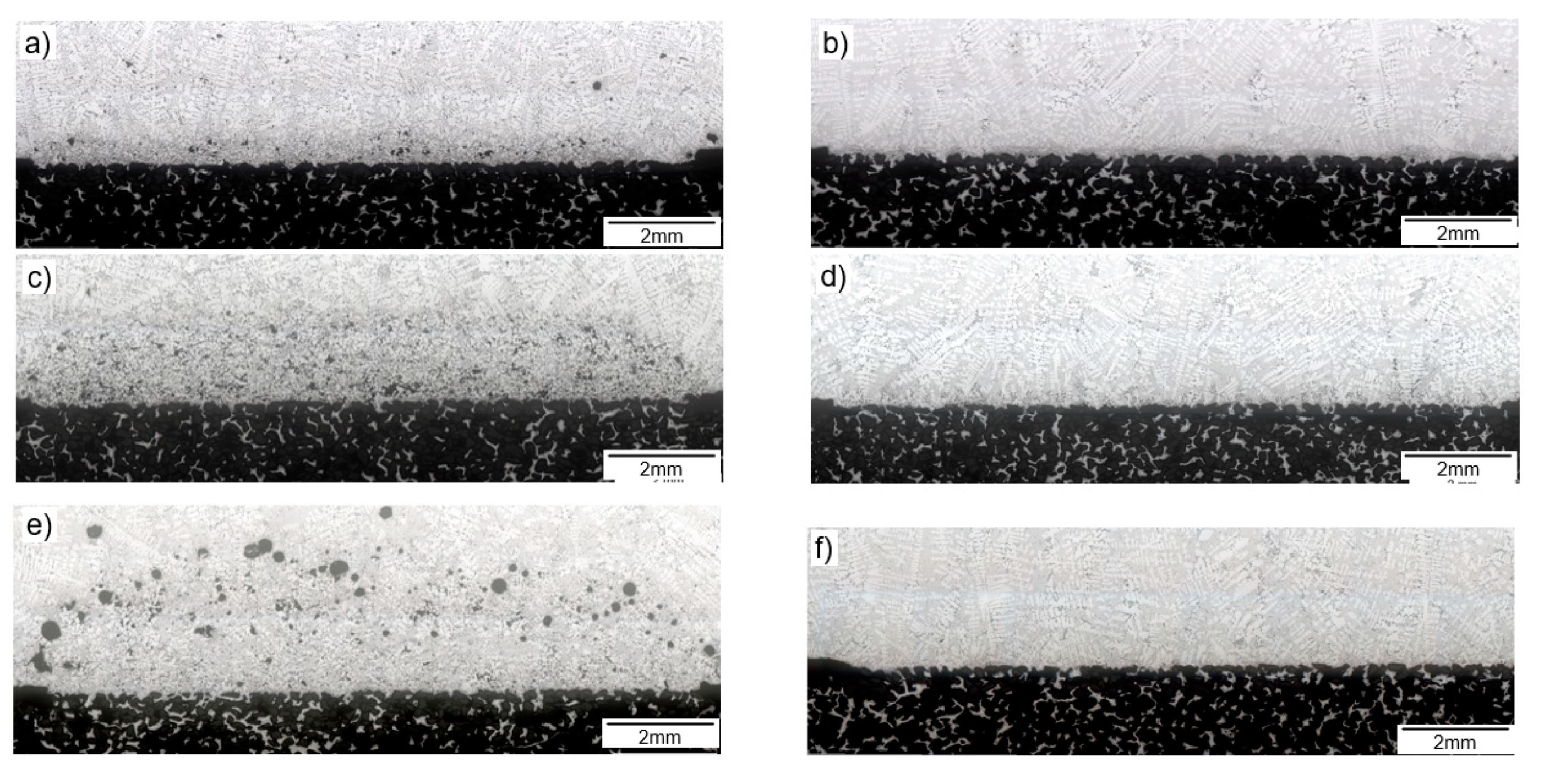
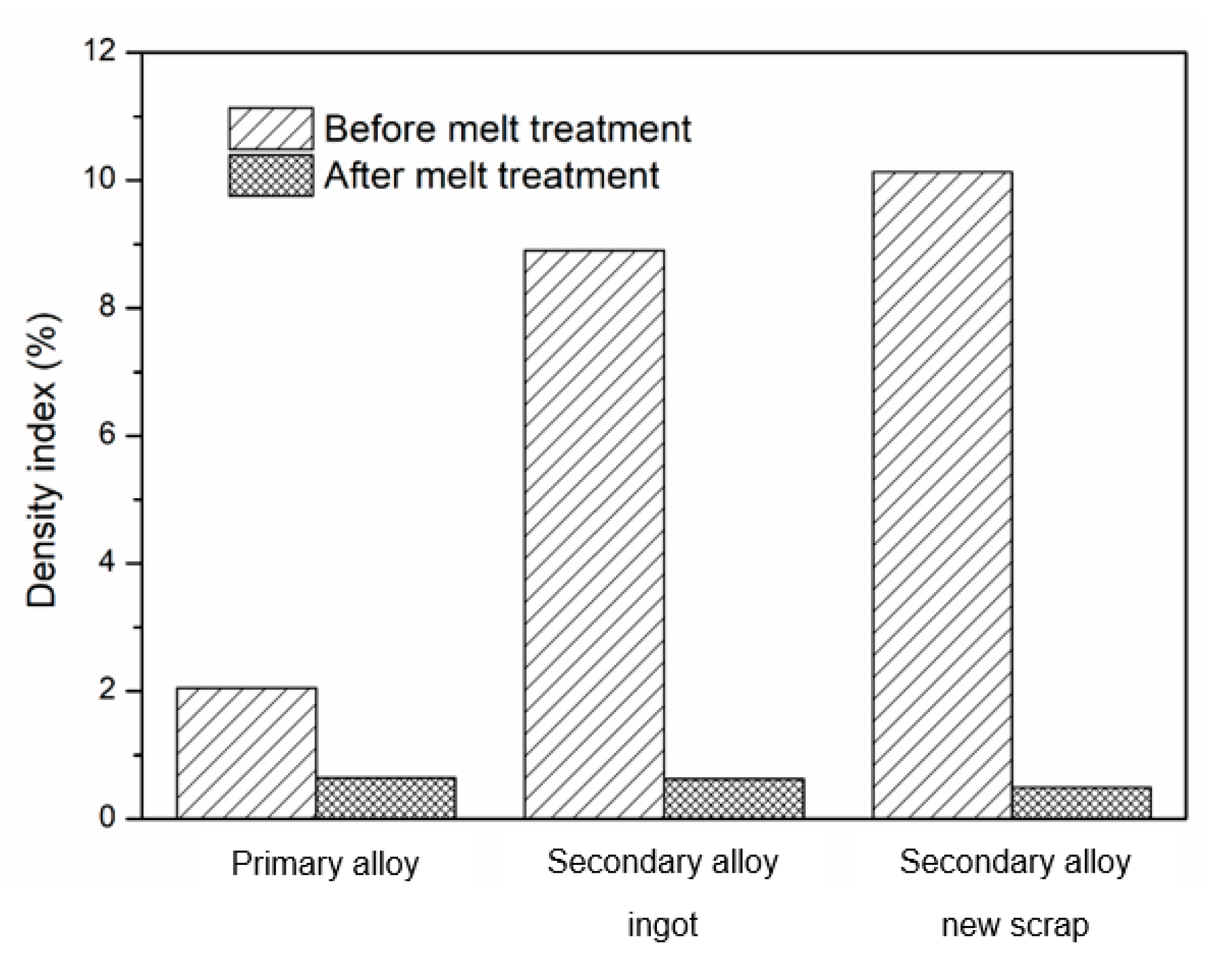
- Density index test: Before the melt treatment, the best value was achieved for the primary aluminium alloy, which was significantly higher than for the rest of the alloys. After the melt treatment, the density index values were very similar (primary alloy = 0.6%; secondary alloy from ingots = 0.5%; secondary alloy made from new scrap = 0.5%) and fulfilled the requirement of < 1%;
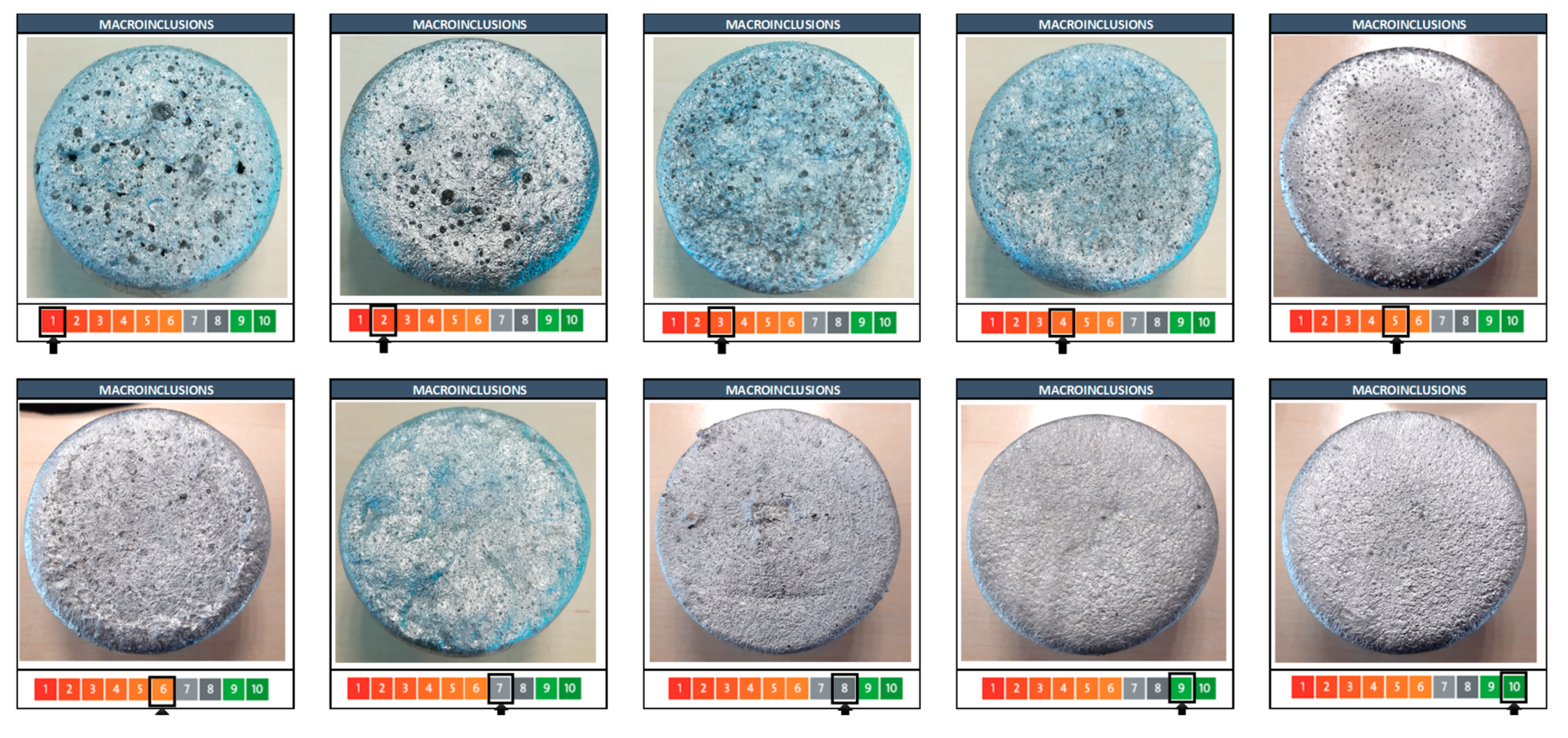
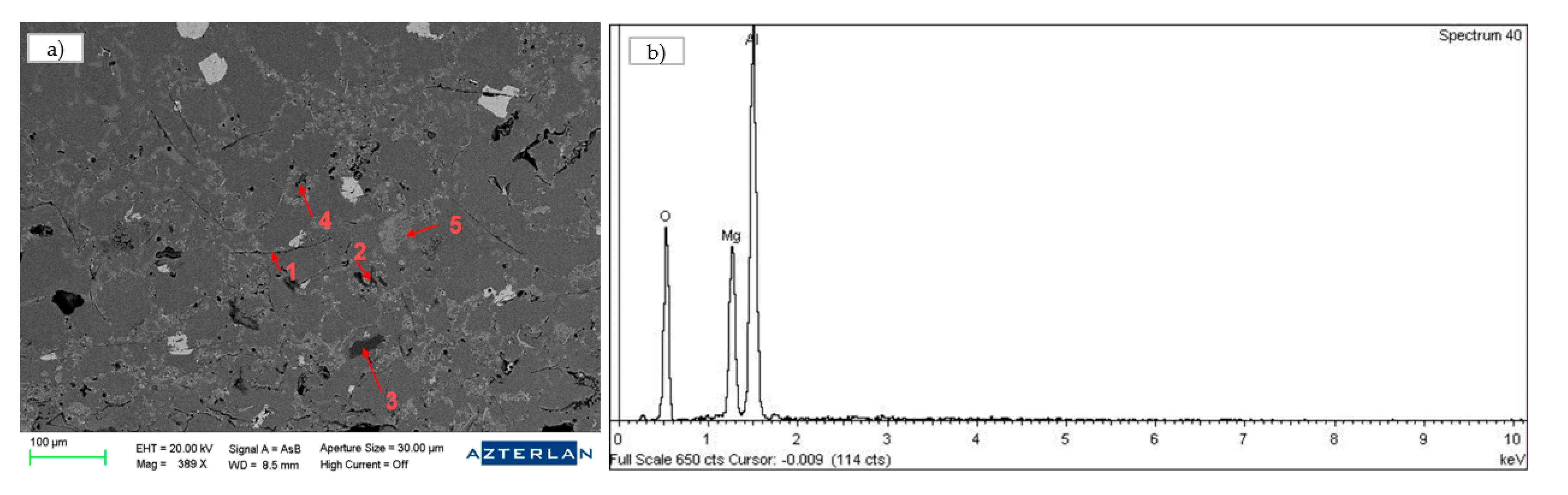
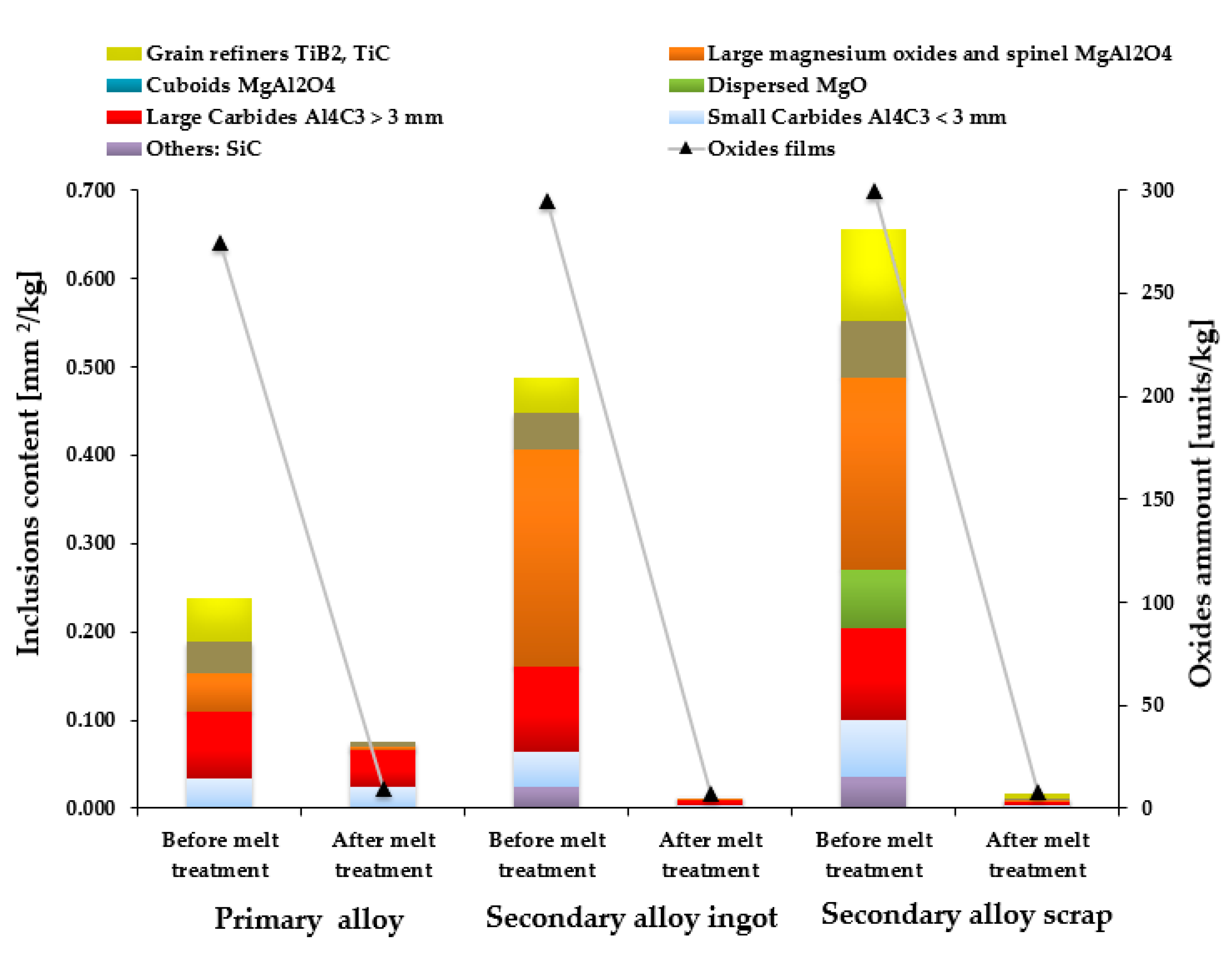
- The primary alloy was the cleanest in the macroinclusion and microinclusion tests before the melt treatment in comparison with the two secondary alloys, with the alloy from new scrap being the worst. After the melt treatment, the macroinclusion and the microinclusion levels were very similar in all three alloys. The macroinclusion levels were certainly very good, with all alloys showing a value of 9 on a scale of 1 to 10. In terms of the microinclusion level, the melt fulfilled the requirements of the inclusion content being lower than 0.1 mm2/kg and the oxide film amounting to less than 10 units per kg in the three alloys.
- Modification rates of 1 were increased to 4 via chemical composition adjustment of Sr;
- Density indexes of 10.1% can be brought down to 0.5% by degassing the melt using Ar rotor technology;
- Macroinclusion levels of 3 can be improved to 9 using Ar rotor technology and flux-aided floatation and skimming;
- The microinclusion film content can be reduced from 300 units/kg to less than 10 units/kg and from 0.69 mm2/kg to 0.01 mm2/kg using Ar rotor technology and flux-aided floatation and skimming.
Author Contributions
Funding
Institutional Review Board Statement
Informed Consent Statement
Data Availability Statement
Acknowledgments
Conflicts of Interest
References
- Luszczak, M. Development of High Pressure Die Casting Structural Components at Nemak Poland. In Proceedings of the 2nd International Forum: Vacuum Die Casting: Structural Parts, Territet Montreux, Fondarex, Switzerland, 25 March 2015. [Google Scholar]
- Menk, W. Automotive components in Al High Pressure Die Casting: Light weight challenge and material development. In Proceedings of the 3rd International Technical Forum on the HPDC Technology, Amorebieta, Spain, 26 November 2015. [Google Scholar]
- Rheinfeldeng Alloys GmbH & Co. KG. Handbuch Primary Aluminium Casting Alloys; Rheinfeldeng Alloys GmbH & Co. KG: Rheinfelden, Germany, 2010. [Google Scholar]
- Cecchel, S.; Ferrario, D.; Panvini, A.; Cornacchia, G. Lightweight of a cross beam for commercial vehicles: Development, testing and validation. Mater. Des. 2018, 149, 122–134. [Google Scholar] [CrossRef]
- Teichmann, F.; Ziemer, A.; Leitner, M.; Hensel, J.; Dilger, K. Linear Elastic FE-Analysis of Porous, Laser Welded, Heat Treatable, Aluminium High Pressure Die Castings based on X-Ray Computed Tomography Data. Materials 2020, 13, 1420. [Google Scholar] [CrossRef] [Green Version]
- Dobrzański, L.A.; Maniara, R.; Sokolowski, J.H. The effect of cast Al-Si-Cu alloy solidification rate on alloy thermal characteristics. J. Achiev. Mater. Manuf. Eng. 2006, 17, 217–220. [Google Scholar]
- Salas, A.E.; Altamirano Guerrero, R.G.; Rodríguez Ortiz, G.; Reyes Gasga, J.; García Robledo, J.F.; Lozada Flores, O.; Sheilla Costa, P. Microstructural, microscratch and nanohardness mechanical characterization of secondary commercial HPDC AlSi9Cu3-type alloy. J. Mater. Res. Technol. 2020, 9, 8266–8282. [Google Scholar] [CrossRef]
- Hu, X.P.; Fang, L.; Zhou, J.X.; Zhang, X.Z.; Hu, H. Characterization and kinetic modeling of secondary phases in squeeze cast Al alloy A380 by DSC thermal analysis. China Foundry 2017, 14, 98–107. [Google Scholar] [CrossRef] [Green Version]
- Niklas, A.; Bakedano, A.; Orden, S.; Da Silva, M.; Nogues, E.; Fernandez-Calvo, A.I. Effect of microstruture and casting defects on the mechanical properties of secondary AlSi10MnMg(Fe) test parts manufactured by vacuum assisted high pressure die casting technology. Mater. Today Proc. 2015, 2, 4931–4938. [Google Scholar] [CrossRef]
- Rheinfeldeng Alloys GmbH & Co. KG. Handbuch Druckguss Sf-36 Ci-37 Ma-59 Ma-33; Rheinfeldeng Alloys GmbH & Co. KG: Rheinfelden, Germany, 2007. [Google Scholar]
- Niklas, A.; Bakedano, A.; Orden, S.; Da Silva, M.; Nogues, E.; Fernandez-Calvo, A.I. Microstructure and Mechanical properties of a new secondary AlSi10MnMg(Fe) alloy for ductile high pressure die casting parts for the automotive industry. Key Eng. Mater. 2016, 710, 244–249. [Google Scholar] [CrossRef]
- Gustafsson, G.; Thorvaldsosson, T.; Dunlop, G.L. The influence of Fe, Mn and Cr on the microstructures of cast Al-Si alloys. Metall. Trans. 1986, 17A, 45–52. [Google Scholar] [CrossRef]
- Trimal®-05 The High Pressure Die Casting Alloy for Crash Relevant Application. Trimet Aluminium Ag. Available online: https://www.bohaitrimet.com/fileadmin/user_upload/AGB_Downloads/product-sheet_trimal-05_gb.pdf (accessed on 27 May 2021).
- Rheinfeldeng Alloys GmbH & Co. KG. Optimizing the Mn and Mg content for structural application Silafont®-36, AlSi9MgMn. In Proceedings of the 22nd Internationational Die Casting Congress and Exposition by NADCA, Indianapolis, Indiana, 15–17 September 2003. [Google Scholar]
- Seifeddine, S.; Svensson, I.L. The influence of Fe and Mn content and cooling rate on the microstructure and mechanical properties of A380-die casting alloys. Metall. Sci. Technol. 2009, 27, 11–13. [Google Scholar]
- Backerud, S.L.; Chai, G.; Tamminen, J. Solidification Characteristics of Aluminium Alloys. AFS 1990, 2, 71–84. [Google Scholar]
- Lu, L.; Dahle, A.K. Iron-rich intermetallic phases and their role in casting defect formation in hypoeutectic Al-Si alloys. Metall. Mater. Trans. 2005, 36, 819–835. [Google Scholar]
- Gowri, S.; Samuel, F.H. Effect of alloying elements on the solidification characteristics and microstructure of Al-Si-Cu-Mg-Fe 380 alloy. Metall. Mater. Trans. 1994, 25, 437–448. [Google Scholar] [CrossRef]
- Samuel, A.M.; Samuel, F.H.; Villeneuve, C.; Doty, H.W.; Valtierra, S. Effect of trace elements on β-Al5FeSi characteristics, porosity and tensile properties of Al-Si-Cu (319) cast alloys. Int. J. Cast Met. Res. 2001, 14, 97–120. [Google Scholar] [CrossRef]
- Shabestari, S.G. The effect of iron and manganese on the formation of intermetallic compounds in aluminium–silicon alloys. Mater. Sci. Eng. A 2004, 383, 289–298. [Google Scholar] [CrossRef]
- Ashtari, P.; Tezuka, H.; Sato, T. Influence of Sr and Mn Additions on Intermetallic Compound Morphologies in Al-Si-Cu-Fe Cast Alloys. Mater. Trans. 2003, 44, 2611–2616. [Google Scholar] [CrossRef] [Green Version]
- Shabestari, S.G.; Gruzleski, J.E. Gravity segregation of complex intermetallic compounds in liquid aluminium-silicon alloys. Metall. Mater. AFS Trans. 1995, 26, 999–1006. [Google Scholar] [CrossRef]
- De la Fuente, E.; Alfaro, I.; Niklas, A.; Anza, I.; Fernández-Calvo, A.I. Improved microstructure and mechanical properties of a recycled AlSi7Mg 0.3 alloy with 0.3 wt.% Fe by small additions of Mn, Cr and V. In Proceedings of the 48th Aluminium Two Thousand Congress, Milan, Italy, 14–18 May 2013. [Google Scholar]
- Niklas, A.; González-Martínez, R.; Orden, S.; Bakedano, A.; Garat, M.; Fernández-Calvo, A.I. Effect of Wall Thickness and Manganese Additions on the formation of intermetallic iron phases in new secondary alloys suitable for vacuum assisted HPDC. In Proceedings of the 121st Metalcasting Congress, Milwaukee, WI, USA, 25–27 April 2017. [Google Scholar]
- Fernández, A.I.; Niklas, A.; Alfaro Abreu, I.; Anza Ortiz de Apodaca, I. Method for Obtaining Improved Mechanical Properties in Recycled Aluminium Casting Free of Platelet-Shaped Beta-Phases. Granted Patent EP 2471967B1, 28 December 2010. [Google Scholar]
- Anantha Narayanan, L.; Samuel, J.E.; Gruzleski, J.E. Crystallization behavior of iron-containing intermetallic compounds in 319 aluminium alloy. Metall. Mater. Trans. A 1994, 25, 1761–1773. [Google Scholar] [CrossRef]
- Hurtalova, L.; Tillova, E.; Chalupova, M. Microstructural and Vicker Microhardness Evolution of Heat Treated Secondary Aluminium Cast Alloy. Key Eng. Mater. 2013, 586, 137–140. [Google Scholar] [CrossRef]
- Das, K.S.; Gren, J.A.S. Aluminium Industry and Climate Change-Assessment and Responses. J. Miner. Met. Mater. Soc. 2010, 62, 27–31. [Google Scholar] [CrossRef]
- Soo, V.K.; Peeters, J.; Paraskevas, D.; Compston, P.; Doolan, M.; Duflou, J.R. Economic and Environmental Evaluation of Alu-minium Recycling based on a Belgian Case Study. In Proceedings of the 16th Global Conference on Sustainable Manufacturing, Lexington, KY, USA, 4 October 2018. [Google Scholar]
- Soo, V.K.; Peeters, J.; Paraskevas, D.; Compston, P.; Doolan, M.; Duflou, J.R. Sustainable aluminium recycling of end-of-life products: A joining techniques perspective. J. Clean. Prod. 2018, 178, 119–132. [Google Scholar] [CrossRef] [Green Version]
- Wetzel, C.S. Benchmarking Melting. Mod. Cast. 2012, 102, 18–21. [Google Scholar]
- Niklas, A.; Abaunza, U.; Fernández-Calvo, A.I.; Lacaze, J.; Suarez, R. Thermal analysis as a microstructure prediction tool for A356 aluminium parts solidified under various cooling conditions. In Proceedings of the 69th World Foundry Congress (WFC), Hangzhou, China, 20 October 2010. [Google Scholar]
- Roos, H. Optimization of the HPDC process. In Proceedings of the Technical Forum Buhler, Madrid, Spain, 18 October 2016. [Google Scholar]
- Brochure—PoDFA. The Complete Solution for Inclusion Measurement|Inclusion Identification and Quantification Analysis. ABB Inc. Process Automation Measurement & Analytics. Available online: https://library.abb.com/es/results (accessed on 9 June 2021).


| Reference | Stages | Si | Fe | Cu | Mn | Mg | Cr | Zn | Ti | Sr |
|---|---|---|---|---|---|---|---|---|---|---|
| Primary alloy AlSi10MnMg | Before melt treatment | 10.6 | 0.11 | 0.01 | 0.54 | 0.29 | 0.001 | 0.012 | 0.068 | 0.006 |
| After melt treatment | 10.6 | 0.12 | 0.01 | 0.53 | 0.30 | 0.001 | 0.012 | 0.072 | 0.015 | |
| Secondary alloy AlSi10MnMg(Fe) from ingots | Before melt treatment | 9.67 | 0.62 | 0.03 | 0.42 | 0.35 | <0.01 | 0.015 | 0.053 | <0.005 |
| After melt treatment | 9.90 | 0.64 | 0.03 | 0.42 | 0.34 | <0.01 | 0.015 | 0.052 | 0.013 | |
| Secondary alloy AlSi10MnMg(Fe) from new scrap | Before melt treatment | 11.0 | 0.62 | 0.04 | 0.45 | 0.51 | <0.01 | 0.021 | 0.076 | 0.010 |
| After melt treatment | 10.8 | 0.61 | 0.04 | 0.43 | 0.52 | <0.01 | 0.020 | 0.073 | 0.018 |
| Reference | Stages | TAl Prim min (°C) | Recal Prim (°C) | TEutec min (°C) | Modification Rate Prediction |
|---|---|---|---|---|---|
| Primary alloy | Before melt treatment | 586.6 | 1.1 | 573.2 | 1–2 |
| After melt treatment | 584.7 | 1.5 | 566.5 | 4 | |
| Secondary alloy from ingots | Before melt treatment | 590.5 | 1.1 | 573.0 | 1–2 |
| After melt treatment | 590.1 | 1.1 | 564.5 | 4 | |
| Secondary alloy from new scrap | Before melt treatment | 582.9 | 1.6 | 564.3 | 4 |
| After melt treatment | 581.7 | 1.8 | 563.9 | 4 |
| Reference | Sample before Melt Treatment | Sample after Melt Treatment |
|---|---|---|
| Primary alloy | 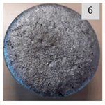 |  |
| Secondary alloy from ingots | 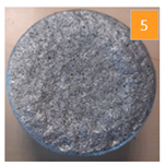 |  |
| Secondary alloy from new scrap |  | 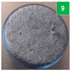 |
| Reference | Stages | Filtered Weight (g) | Unfiltered Weight (g) | Total Weight (g) |
|---|---|---|---|---|
| Primary alloy | Before melt treatment | 1081 | 942 | 2024 |
| After melt treatment | 1232 | 660 | 1892 | |
| Secondary alloy from ingots | Before melt treatment | 1284 | 851 | 2135 |
| After melt treatment | 1360 | 614 | 1974 | |
| Secondary alloy from new scrap | Before melt treatment | 1051 | 995 | 2046 |
| After melt treatment | 1218 | 731 | 1949 |
| Reference | Before Met Treatment | After Melt Treatment |
|---|---|---|
| Primary alloy | 472 µm | 229 µm |
| Secondary alloy from ingots | 1660 µm | <80 µm |
| Secondary alloy from scrap | 2766 µm | <80 µm |
Publisher’s Note: MDPI stays neutral with regard to jurisdictional claims in published maps and institutional affiliations. |
© 2021 by the authors. Licensee MDPI, Basel, Switzerland. This article is an open access article distributed under the terms and conditions of the Creative Commons Attribution (CC BY) license (https://creativecommons.org/licenses/by/4.0/).
Share and Cite
Bakedano, A.; Niklas, A.; Fernández-Calvo, A.I.; Plata, G.; Lozares, J.; Berlanga-Labari, C. Comparative Study of the Metallurgical Quality of Primary and Secondary AlSi10MnMg Aluminium Alloys. Metals 2021, 11, 1147. https://doi.org/10.3390/met11071147
Bakedano A, Niklas A, Fernández-Calvo AI, Plata G, Lozares J, Berlanga-Labari C. Comparative Study of the Metallurgical Quality of Primary and Secondary AlSi10MnMg Aluminium Alloys. Metals. 2021; 11(7):1147. https://doi.org/10.3390/met11071147
Chicago/Turabian StyleBakedano, Asier, Andrea Niklas, Ana Isabel Fernández-Calvo, Gorka Plata, Jokin Lozares, and Carlos Berlanga-Labari. 2021. "Comparative Study of the Metallurgical Quality of Primary and Secondary AlSi10MnMg Aluminium Alloys" Metals 11, no. 7: 1147. https://doi.org/10.3390/met11071147
APA StyleBakedano, A., Niklas, A., Fernández-Calvo, A. I., Plata, G., Lozares, J., & Berlanga-Labari, C. (2021). Comparative Study of the Metallurgical Quality of Primary and Secondary AlSi10MnMg Aluminium Alloys. Metals, 11(7), 1147. https://doi.org/10.3390/met11071147